1
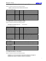
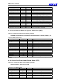
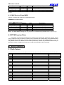
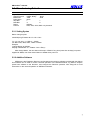
GM-82
GPS Engine Board
User’s Guide
July 18, 2003
Version 2.0
HOLUX
Technology Inc.
8F, 26, Tai-Yuen Street, Tai-Yuen Hi-Tech Industrial Park,
Chu Pei City 302, Hsinchu, Taiwan.
Phone: +886-3-552-6268 Fax: +886-3-552-6108
E-Mail: [email protected] Web: www.holux.com.tw
All Right Reserved
GM-82 User’s manual
TABLE OF CONTENTS
1. Introduction .................................................................................................................................... 3
1.1 Overview................................................................................................................................ 3
1.2 Features ................................................................................................................................. 3
1.3 Technology Specifications............................................................................................. 3
1.3.1 Physical Dimension............................................................................................... 3
1.3.2 Environmental Characteristics ......................................................................... 3
1.3.3 Electrical Characteristics.................................................................................... 3
1.3.4 Performance............................................................................................................. 3
1.3.5 Interfaces................................................................................................................... 4
2. Operational characteristics ...................................................................................................... 4
2.1 Initialization .......................................................................................................................... 4
2.2 Navigation ............................................................................................................................. 5
2.3 Manufacturing Default: .................................................................................................... 5
3. Hardware interface ....................................................................................................................... 5
3.1 Standard Model GM-82..................................................................................................... 5
4. Software Interface ........................................................................................................................ 7
4.1 NMEA Transmitted Messages ....................................................................................... 7
4.1.1 Global Positioning System Fix Data (GGA) ................................................. 7
4.1.2 Geographic Position with Latitude/Longitude(GLL)................................. 8
4.1.3 GNSS DOP and Active Satellites (GSA) ........................................................ 8
4.1.4 GNSS Satellites in View (GSV).......................................................................... 8
4.1.5 Recommended Minimum Specific GNSS Data (RMC).............................. 9
4.1.6 Course Over Ground and Ground Speed (VTG)......................................... 9
4.1.6 MSK Receiver Signal (MSS) ............................................................................. 10
4.2 RTCM Received Data ...................................................................................................... 10
5. Earth Datums .............................................................................................................................. 10
5.1 Earth Datums ..................................................................................................................... 10
5.2 . Manufacturing Default: ................................................................................................ 12
5.2.1 Setting Syntax ....................................................................................................... 12
5.2.2 Addition Software ................................................................................................ 12
6. Ordering Information .............................................................................................................. 13
6.1 Products Options ............................................................................................................. 13
6.2 Accessories........................................................................................................................ 13
6.3 Other Products.................................................................................................................. 13
2
GM-82 User’s manual
1. Introduction
1.1 Overview
The HOLUX GM-82 Engine Board is a total solution GPS receiver, designed based on SiRF star
II/LP Architecture. This positioning application meets strict needs such as car navigation, mapping,
surveying, agriculture and so on. Only clear view of sky and certain power supply are necessary to the unit.
GM-82 communicates with other electronic utilities via compatible dual-channel through RS-232 or
TTL and saves critical satellite data by built–in memory backup. With low power consumption, the GM-82
tracks up to 12 satellites at a time, re-acquires satellite signals in 100 ms and updates position data every
second. Trickle-Power allows the unit operates a fraction of the time and Push-to-Fix permits user to have
a quick position fix even though the receiver usually stays off.
1.2 Features
The GM-82 provides a host of features that make it easy for integration and use.
SiRF Star II/LP chipset with embedded ARM7TDMI CPU available for customized applications in
firmware。
12 parallel satellite-tracking channels for fast acquisition and reacquisition。
High speed signal acquisition using 1920 time/frequency search channels。
Built-in WAAS/EGNOS Demodulator。
Low power consumption with Advanced Trickle-Power and Push-To-Fix mode。。
Optional Rechargeable battery for memory and RTC backup and for fast Time To First Fix(TTFF)。
Support NMEA0183 v2.2 data protocol and SiRF binary code。
Enhanced algorithms -SnapLock and SnapStart provide superior navigation performance in
urban, canyon and foliage environments。
For Car Navigation , Marine Navigation ,Fleet Management ,AVL and Location-Based Services ,
Auto Pilot ,Personal Navigation or touring devices, Tracking devices/systems and Mapping devices
application。
1.3 Technology Specifications
1.3.1 Physical Dimension
1) PCB Size: 40(W) x 50(D) x 12(H) (mm)
2) Weight: 18 g
1.3.2 Environmental Characteristics
1) Operating temperature: -40oC to +85oC (internal temperature)
2) Storage temperature: -45oC to +100oC
1.3.3 Electrical Characteristics
1)
2)
3)
4)
Input voltage: 5.0Vdc +/-10% or 3.3Vdc +/- 10%.
Input current: Less than 80mA (without antenna )
Backup power:(optional). 3V Rechargeable Lithium cell battery, up to 1000 hours discharge.
MCX antenna connector: Active .
1.3.4 Performance
1) Tracks up to 12 satellites.
3
GM-82 User’s manual
2) Update rate: 1 second.
3) Acquisition time:
Reacquisition
Hot start
Warm start
Cold start
0.1
8
38
45
sec, averaged
sec. averaged
sec. averaged
sec. averaged
4) Position accuracy:
Non DGPS (Differential GPS)
Position
5~25
Velocity
0.1
Time
1
meter CEP
meters/second.
microsecond synchronized GPS time
DGPS (Differential GPS)
Position
Velocity
1 to 5
0.05
meters, typical
meters/second, typical
< 2.2
<5
meters, horizontal 95% of time
meters, vertical 95% of time
18,000
515
4
20
meters(60,000 feet) max
meters/second (700 knots) max
G, max
meters/second³, max
EGNOS/WAAS
Position
5)
Dynamic Conditions:
Altitude
Velocity
Acceleration
Jerk
1.3.5 Interfaces
1) Dual communication channel TTL or RS232 levels, with user selectable baud rate (4800-Default,
9600, 19200, 38400).
2) NMEA 0183 Version 2.2 ASCII output (GGA, GSA, GSV, RMC (VTG and GLL for optional)).
3) Real-time Differential Correction input (RTCM SC-104 message types 1, 2 and 9).
2. Operational characteristics
2.1 Initialization
As soon as the initial self-test is complete, the GM-82 begins the process of satellite acquisition and
tracking automatically. Under normal circumstances, it takes approximately 45 seconds to achieve a
position fix, 38 seconds if ephemeris data is known. After a position fix has been calculated, information
about valid position, velocity and time is transmitted over the output channel.
The GM-82 utilizes initial data, such as last stored position, date, time and satellite orbital data, to
achieve maximum acquisition performance. If significant inaccuracy exists in the initial data, or the orbital
data is obsolete, it may take more time to achieve a navigation solution. The GM-82 Auto-locate feature is
capable of automatically determining a navigation solution without intervention from the host system.
However, acquisition performance can be improved as the host system initializes the GM-82 in the following
situation:
Moving further than 500 kilometers.
Failure of Data storage due to the inactive internal memory battery.
4
GM-82 User’s manual
2.2 Navigation
After the acquisition process is complete, the GM-82 sends valid navigation information over output
channels. These data include:
1)
2)
3)
4)
5)
Latitude/longitude/altitude
Velocity
Date/time
Error estimates
Satellite and receiver status
2.3 Manufacturing Default:
Datum: WGS84.
Baud Rate: 4800.
Output: GGA, GSA, GSV, RMC or by demand.
DGPS: RTCM SC-104(Type 1,2,9) or WAAS (in USA area) or EGNOS (in European area)
3. Hardware interface
3.1 Standard Model GM-82
GM-82-A W/ angle MCX connector and standard hole to hole dimension
5
GM-82 User’s manual
J1 connector pin definition:
Pin #
Name
1
NC
2
VCC_5V
3
VBAT
4
NC
Description
No function
Regulated 5.0V +/-5% input power, 80mA typical.
Battery backup input. 2.5V to 3.3V ,10uA typical.
No function
5
PBRESEN
Manual reset input, ground to reset receiver. Leave floating for
normal operation. The minimum plus width is 150 ms reset
signal.
6
7
8
9
10
11
12
13
14
15
16
17
18
19
20
GPIO1
GPIO2
GPIO3
GPIO4
GND
TXA
RXA
GND
TXB
RXB
GND
GPIO5
GND
TIMEMARK
NC
General purpose I/O pin 1
General purpose I/O pin 2
General purpose I/O pin 3
General purpose I/O pin 4
Ground
Port A Serial Transmit Data GPS messages.
Port A Serial Receive Data GPS commands.
Ground
Port B Serial Transmit Data.
Port B Serial Receive Data DGPS messages.
Ground.
Reserved for re-programming flash.
Ground
1PPS Time mark output
No function
1. VCC_5V: + 5V DC voltage input.
2. Dual communication channel TTL levels (GM-82-T0/T1) or RS-232 levels (GM-82-A0/A1), with
user selectable baud rates (4800-Default, 9600, 19200, 38400).
RXA: Main Receive Channel. This input is used to receive software commands to the GM-82 from
user written software.
RXB: Auxiliary Receive Channel. This input is used to receive serial differential GPS data.
TXA: Main Serial Output. This output provides navigation data to user written software.
TXB: For user’s application (not currently used).
3. PBRESEN: This pin provides an active-low reset input to the GM-82. Activation of this pin will reset
and start acquisition process. It may be left open if not utilized.
4. TIMEMARK: This pin provides One-Pulse-Per-Second output from the GM-82 board, which is
synchronized to GPS time. This is not available in Trickle-Power mode.
5. VBAT: Battery backup input for powering the RAM and RTC. Typical current is 10uA. Without an
external backup battery the GM-82 will execute a cold start when turning on each time. To achieve
the faster start-up offered by a hot or warm start, either a battery backup must be connected. A 2.5V
and 3.6V power source is required in order to maximize battery lifetime. With a lithium cell battery,
the data retention is 1,000 hours.
6. GPIO Functions: Several I/Os of CPU are connected to the digital interface connector for
customer’s applications and are labeled as GPIO1 to GPIO5.
6
GM-82 User’s manual
4. Software Interface
The GPS-82 interface protocol is based on the National Marine Electronics Association's NMEA 0183
ASCⅡinterface specification, which is defined in NMEA 0183, Version 2.2 and the Radio Technical
Commission for Maritime Services (RTCM Recommended Standards For Differential Navstar GPS Service,
Version 2.1, RTCM Special Committee No.104).
4.1 NMEA Transmitted Messages
The default communication parameters for NMEA output are 4800 baud, 8 data bits, stop bit, and no
parity.
Table 4-1 NMEA-0183 Output Messages
Description
NMEA Record
Global positioning system fixed data
GPGGA
GPGLL
Geographic position- latitude/longitude
GPGSA
GNSS DOP and active satellites
GPGSV
GNSS satellites in view
GPRMC
Recommended minimum specific GNSS data
GPVTG
Course over ground and ground speed
GPMSS
Radio-beacon Signal-to-noise ratio, signal strength, frequency, etc.
4.1.1 Global Positioning System Fix Data (GGA)
Table 4-2 contains the values for the following example:
$GPGGA,161229.487,3723.2475,N,12158.3416,W,1,07,1.0,9.0,M, , , ,0000*18
Table 4-2 GGA Data Format
Name
Example
Message ID
$GPGGA
UTC Time
161229.487
Latitude
3723.2475
N/S Indicator
N
Longitude
12158.3416
E/W Indicator
W
Position Fix Indicator
1
Satellites Used
07
HDOP
1.0
MSL Altitude (1)
9.0
Units
M
Geoid Separation(1)
Units
M
Age of Diff. Corr.
Diff. Ref. Station ID
0000
Checksum
*18
<CR> <LF>
Units
Description
GGA protocol header
hhmmss.sss
ddmm.mmmm
N=north or S=south
dddmm.mmmm
E=east or W=west
See Table 5-3
Range 0 to 12
Horizontal Dilution of Precision
Meters
Meters
Meters
Meters
second Null fields when DGPS is not used
End of message termination
(1). SiRF Technology Inc. does not support geoid corrections. Values are WGS84 ellipsoid heights.
Table 4-3 Position Fix Indicator
Value
0
1
2
3
Description
0 Fix not available or invalid
GPS SPS Mode, fix valid
Differential GPS, SPS Mode, fix valid
GPS PPS Mode, fix valid
7
GM-82 User’s manual
4.1.2 Geographic Position with Latitude/Longitude(GLL)
Table 4-4 contains the values for the following example:
$GPGLL,3723.2475,N,12158.3416,W,161229.487,A*2C
Table 4-4 GLL Data Format
Name
Example
Message ID
Latitude
N/S Indicator
Longitude
E/W Indicator
UTC Position
Status
Checksum
<CR> <LF>
Units
$GPGLL
3723.2475
N
12158.3416
W
161229.487
A
*2C
Description
GLL protocol header
ddmm.mmmm
N/S Indicator N N=north or S=south
dddmm.mmmm
E=east or W=west
hhmmss.sss
A=data valid or V=data not valid
End of message termination
4.1.3 GNSS DOP and Active Satellites (GSA)
Table 4-5 contains the values for the following example:
$GPGSA,A,3,07,02,26,27,09,04,15, , , , , ,1.8,1.0,1.5*33
Table 4-5 GSA Data Format
Name
Example
Message ID
Mode 1
Mode 2
Satellite Used(1)
Satellite Used(1)
……
Satellite Used(1)
PDOP
HDOP
VDOP
Checksum
<CR> <LF>
Units
$GPGSA
A
3
07
02
1.8
1.0
1.5
*33
Description
GSA protocol header
See Table 5-6
See Table 5-7
Sv on Channel 1
Sv on Channel 2
….
Sv on Channel 12
Position Dilution of Precision
Horizontal Dilution of Precision
Vertical Dilution of Precision
End of message termination
1. Satellite used in solution.
Table 4-6 Mode 1
Value
M
A
Table 4-7 Mode 2
Value
1
2
3
Description
Manual—forced to operate in 2D or 3D mode
2DAutomatic—allowed to automatically switch 2D/3D
Description
Fix Not Available
2D
3D
4.1.4 GNSS Satellites in View (GSV)
Table 4-8 contains the values for the following example:
$GPGSV,2,1,07,07,79,048,42,02,51,062,43,26,36,256,42,27,27,138,42*71
$GPGSV,2,2,07,09,23,313,42,04,19,159,41,15,12,041,42*41
8
GM-82 User’s manual
Table 4-8 GSV Data Format
Name
Example
Units
Description
Message ID
$GPGSV
GSV protocol header
Number of Messages(1)
2
Range 1 to 3
Message Number(1)
1
Range 1 to 3
Satellites in View
07
Satellite ID
07
Channel 1 (Range 1 to 32)
Elevation
79
degrees Channel 1 (Maximum 90)
Azimuth
048
degrees Channel 1 (True, Range 0 to 359)
SNR (C/No)
42
dBHz Range 0 to 99, null when not tracking
....
....
Satellite ID
27
Channel 4 (Range 1 to 32)
Elevation
27
degrees Channel 4 (Maximum 90)
Azimuth
138
degrees Channel 4 (True, Range 0 to 359)
SNR (C/No)
42
dBHz Range 0 to 99, null when not tracking
Checksum
*71
<CR> <LF>
End of message termination
(1). Depending on the number of satellites tracked multiple messages of GSV data may be required.
4.1.5 Recommended Minimum Specific GNSS Data (RMC)
Table 4-9 contains the values for the following example:
$GPRMC,161229.487,A,3723.2475,N,12158.3416,W,0.13,309.62,120598, ,*10
Table 4-9 RMC Data Format
Name
Example
Message ID
UTC Time
Status
Latitude
N/S Indicator
Longitude
E/W Indicator
Speed Over Ground
Course Over Ground
Date
Magnetic Variation(1)
Checksum
<CR> <LF>
$GPRMC
161229.487
A
3723.2475
N
12158.3416
W
0.13
309.62
120598
Units
Description
RMC protocol header
hhmmss.sss
A=data valid or V=data not valid
ddmm.mmmm
N=north or S=south
dddmm.mmmm
E=east or W=west
knots
degrees True
ddmmyy
degrees E=east or W=west
*10
End of message termination
(1). SiRF Technology Inc. does not support magnetic declination. All “course over ground” data are geodetic WGS84
directions.
4.1.6 Course Over Ground and Ground Speed (VTG)
Table 4-10 contains the values for the following example:
$GPVTG,309.62,T, ,M,0.13,N,0.2,K*6E
Table 4-10 VTG Data Format
Name
Example
Message ID
Course
Reference
Course
Reference
Speed
Units
$GPVTG
309.62
T
M
0.13
N
Units
Description
VTG protocol header
degrees Measured heading
True
degrees Measured heading
Magnetic(1)
knots Measured horizontal speed
Knots
9
GM-82 User’s manual
Speed
Units
Checksum
<CR> <LF>
0.2
K
*6E
km/hr
Measured horizontal speed
Kilometers per hour
End of message termination
(1). SiRF Technology Inc. does not support magnetic declination. All “course over ground” data are geodetic WGS84
directions.
4.1.6 MSK Receiver Signal (MSS)
Table C-9 contains the values for the following example:
$GPMSS,55,27,318.0,100,*66
Table C-9 MSS Data Format
Name
Example
Message ID
$GPMSS
Signal Strength
55
Signal-to-Noise Ratio
27
Beacon Frequency
318.0
Beacon Bit Rate
100
Units
MSS
dB
dB
kHz
Description
protocol header
dB SS of tracked frequency
SNR of tracked frequency
Currently tracked frequency
100 bits per second
Note – The MSS NMEA message can only be polled or scheduled using the MSK NMEA input message.
4.2 RTCM Received Data
The default communication parameters for DGPS Input are 9600 baud, 8 data bits, stop bit, and no
parity. Position accuracy of less than 5 meters can be achieved with the GPS-82 by using Differential GPS
(DGPS) real-time pseudo-range correction data in RTCM SC-104 format, with message types 1,2, or 9. As
using DGPS receiver with different communication parameters, GPS-82 may decode the data correctly to
generate accurate messages and save them in battery-back SRAM for later computing.
5. Earth Datums
5.1 Earth Datums
The following is a list of the GM-82 earth datum index and the corresponding
Item
Datum
Reference Ellipsoid
1
Adindan - Ethiopia
Clarke 1880
2
Afgooye - Somalia
Krassovsky
3
Alaska, Conus – North American 1983 GRS 1980
4
Argentina
South American 1969
5
International
Bahrain – Ain el ABD 1970
6
Bangladesh
Everest 1830
7
Clarke 1880
Botswana – ARC 1950
8
Bolivia
South American 1969
9
Brazil
South American 1969
10 Canada – North American 1983
GRS 1980
11 Colombia – Provisional American 1956 International
12 Colombia
South American 1969
13 Chile
South American 1969
14 Ecuador
South American 1969
15 European 1950 - Cyprus
International
16 European 1950 – Eastern Regional Mean International
17 European 1950 – Egypt
International
18 European 1950 – Finland, Norway
International
19 European 1950 – Greece
International
earth datum name:
Data name
Data1.dat
Data2.dat
Data3.dat
Data4.dat
Data5.dat
Data6.dat
Data7.dat
Data8.dat
Data9.dat
Data10.dat
Data11.dat
Data12.dat
Data13.dat
Data14.dat
Data15.dat
Data16.dat
Data17.dat
Data18.dat
Data19.dat
10
GM-82 User’s manual
20
21
22
23
24
25
26
27
28
29
30
31
32
33
34
35
36
37
38
39
40
41
42
43
44
45
46
47
48
49
50
51
52
53
54
55
56
57
58
59
60
61
62
63
64
65
66
67
68
69
70
71
European 1950 - Iran
International
International
European 1950 – Italy (Sardinia)
International
European 1950 – Italy (Sicily)
International
European 1950 – Malta
European 1950 – Northern Regional Mean International
International
European 1950 – Portugal, Spain
European 1950 – Southern Regional Mean International
International
European 1950 – Tunisia
European 1950 – Western Regional mean International
European 1950 – Central Regional Mean International
Guyana - South American 1969
South American 1969
Hong Kong
International
Hawaii-North American 1983
GRS1980
Hu_Tsu_Shan Taiwan
International
Indian 1960
Everest 1830
Ireland - 1965
Modified Airy
Liberia - 1964
Clarke 1880
Brunel, East Malaysia
Everest (Sabah & Sarawak)
Mexcio, central America
GRS1980
OMAN
Clarke 1880
Pakistan
Everest 1830
Peru1 - South American 1969
South American 1969
Paraguay - South American 1969
South American 1969
Philippines
Clarke 1866
Clarke 1866
Puerto Rico – Virgin Islands
Qatar national
International
International
Qornoq – Greenland (SOUTH)
International
Reunion – Mascarene Islands
Regional Mean
South American 1969
International
Rome 1940 – Italy
Saudi Arabia- Ain el Abd 1970
International
Singapore
Modified Fischer 1960
South Africa
Clarke 1880
Kenya, Tanzania- ARC 1960
Clarke 1880
Thailand 1975
Everest 1830
Trinidad, Tobago
South American 1969
Venezuela – Provisional American 1956 International
Venezuela
South American 1969
WGS84
WGS84
Tokyo_Mean
Bessel 1841
Tokyo_Japan
Bessel 1841
Tokyo_Korea
Bessel 1841
Tokyo_Okinawa
Bessel 1841
Krassovsky 1940
Albania – S-42(Pulkovo 1942)
Czechoslovakia – S-42(Pulkovo 1942) Krassovsky 1940
Krassovsky 1940
Hungary – S-42(Pulkovo 1942)
Krassovsky 1940
Kazakhstan – S-42(Pulkovo 1942)
Krassovsky 1940
Latvia – S-42(Pulkovo 1942)
Krassovsky 1940
Poland – S-42(Pulkovo 1942)
Krassovsky 1940
Romania – S-42(Pulkovo 1942)
Australia
Australian – National
Potsdam
Bessel 1841
Data20.dat
Data21.dat
Data22.dat
Data23.dat
Data24.dat
Data25.dat
Data26.dat
Data27.dat
Data28.dat
Data29.dat
Data30.dat
Data31.dat
Data32.dat
Data33.dat
Data34.dat
Data35.dat
Data36.dat
Data37.dat
Data38.dat
Data39.dat
Data40.dat
Data41.dat
Data42.dat
Data43.dat
Data44.dat
Data45.dat
Data46.dat
Data47.dat
Data48.dat
Data49.dat
Data50.dat
Data51.dat
Data52.dat
Data53.dat
Data54.dat
Data55.dat
Data56.dat
Data57.dat
Data58.dat
Data59.dat
Data60.dat
Data61.dat
Data62.dat
Data63.dat
Data64.dat
Data65.dat
Data65.dat
Data67.dat
Data68.dat
Data69.dat
Data70.dat
Data71.dat
11
GM-82 User’s manual
5.2 . Manufacturing Default:
Parameter
Input Protocol
Output Protocol
Baud Rate
Parity None
Stop Bits
Data Bits
Datum:
Protocol
Com A
Com B
NMEA Binary
RTCM SC-104
NMEA Binary
None
4800
9600
None
1
1
8
8
WGS84.
GGA, GSA, GSV, RMC or by demand.
5.2.1 Setting Syntax
Datum change syntax:
>DOS\Sirfprog /Fdataxx.dat –Px –Bx –Csh1
-Px: x is com port, 1= COM1 2 = COM2
-Bx: Baud rate, 4800, 9600, 19200 or 38400
Example:
Change Datum to WGS84,
Sirfprog /Fdata58.dat –P1 –B4800 –Csh1 <Entry>
After change datum, the new datum will keep in SRAM. If long time (more than 20 days) no power
supplied to GM82, user must resend datum to GM82 when power on.
5.2.2 Addition Software
SiRFdemo is the Evaluation Receiver configuration and monitoring software provided with the GM-82.
This software can be used to monitor real-time operation of the GM-82 Receiver, log data for analysis,
upload new software to the Receiver, and configure the Receiver operation. See setup.pdf for more
information on the use and operation of SiRFdemo software.
12
GM-82 User’s manual
6. Ordering Information
6.1 Products Options
Model No.
GM-82-A0X-5
GM-82-A0X-3
GM-82-A0A-5
GM-82-A0A-3
GM-82-A1X-5
GM-82-A1X-3
GM-82-A1A-5
GM-82-A1A-3
GM-82-T0X-5
GM-82-T0X-3
GM-82-T0A-5
GM-82-T0A-3
GM-82-T1X-5
GM-82-T1X-3
GM-82-T1A-5
GM-82-T1A-3
Output
Back-up battery Input
Level
Type
Power
TTL or RS-232 Lithium
No
Volt.
RS-232
Y
5
RS-232
Y
3
RS-232
Y
5
RS-232
Y
3
RS-232
Y
5
RS-232
Y
3
RS-232
Y
5
RS-232
Y
3
TTL
Y
5
TTL
Y
3
TTL
Y
5
TTL
Y
3
TTL
Y
5
TTL
Y
3
TTL
Y
5
TTL
Y
3
Power
Saving
Y
Y
Y
Y
Y
Y
Y
Y
-
Connector
Type
MCX
SMA
Y
Y
Y
Y
Y
Y
Y
Y
Y
Y
Y
Y
Y
Y
Y
Y
6.2 Accessories
Option Active antenna .
Part No.
A-10003
A-1000305
A-30503
A-3050305
Cable length
2M
5M
Y
Y
Y
Y
Connector
MCX
SMA
Y
Y
Y
Y
6.3 Other Products
SiRF START II GPS Receiver: GM-210
Palm Vx GPS Receiver: GM-250.
Palm M500/505 GPS Receiver: GM-251.
Handheld GPS: GM-100/GM-305/GM-101.
CF CARD Type GPS Receiver: GM-270
Bluetooth GPS Receiver: GR-230
Mini GPS Receiver: GR-211
13