1
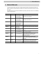
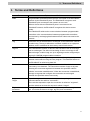
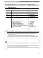
CJ Series
EtherNet/IPTM Connection Guide
OMRON Corporation
Vision System
(FH Series)
P575-E1-02
About Intellectual Property Rights and Trademarks
Microsoft product screen shots reprinted with permission from Microsoft Corporation.
Windows is a registered trademark of Microsoft Corporation in the USA and other countries.
ODVA and EtherNet/IPTM are trademarks of ODVA.
Company names and product names in this document are the trademarks or registered
trademarks of their respective companies.
Table of Contents
1.
Related Manuals .......................................................................................... 1
2.
Terms and Definitions................................................................................. 2
3.
Precautions .................................................................................................. 3
4.
Overview ...................................................................................................... 4
5.
Applicable Devices and Device Configuration ........................................ 5
6.
7.
8.
9.
5.1.
Applicable Devices .............................................................................. 5
5.2.
Device Configuration ........................................................................... 6
EtherNet/IP Settings.................................................................................... 8
6.1.
Parameters .......................................................................................... 8
6.2.
Allocating the Tag Data Links ............................................................ 10
EtherNet/IP Connection Procedure ......................................................... 12
7.1.
Work Flow .......................................................................................... 12
7.2.
Setting up the FH Sensor Controller ................................................. 13
7.3.
Setting up the PLC ............................................................................ 19
7.4.
Setting up the Network ...................................................................... 28
7.5.
Checking the EtherNet/IP Communications ...................................... 42
Initialization Method.................................................................................. 47
8.1.
Initializing the PLC ............................................................................. 47
8.2.
Initializing the FH Sensor Controller .................................................. 48
Revision History ........................................................................................ 49
1.Related Manuals
1. Related Manuals
To ensure system safety, make sure to always read and heed the information provided in all
Safety Precautions and Precautions for Safe Use of manuals for each device which is used in
the system.
The table below lists the manuals of OMRON Corporation (hereinafter referred to as OMRON)
related to this document.
Manufacturer
OMRON
Cat. No.
W472
Model
Manual name
CJ2M-CPU[][]
CJ-series CJ2 CPU Unit
CJ2H-CPU6[]
Hardware User's Manual
CJ2H-CPU6[]-EIP
OMRON
W473
CJ2M-CPU[][]
CJ-series CJ2 CPU Unit
CJ2H-CPU6[]
Software User's Manual
CJ2H-CPU6[]-EIP
OMRON
W465
CJ1W-EIP21
EtherNet/IPTM Units Operation Manual
CJ2H-CPU6[]-EIP
OMRON
W446
CJ2M-CPU3[]
-
OMRON
0969584-7
W4S1-05[]
Switching Hub W4S1-series User's Manual
2285550-0
W4S1-03B
FH-1050/3050
FH-1050/3050-[]0
Image Processing System Instruction
FH-1050/3050
FH-1050/3050-[]0
Vision Sensor FH/FZ5 Series Vision
FH-1050/3050
FH-1050/3050-[]0
Vision Sensor FH/FZ5 Series Vision
OMRON
OMRON
OMRON
Z340
Z341
CX-Programmer Operation Manual
Sheet
System User’s Manual
System Processing Item Function
Reference Manual
OMRON
Z342
FH-1050/3050
FH-1050/3050-[]0
Vision Sensor FH/FZ5 Series Vision
System User’s Manual for Communications
Settings
OMRON
OMRON
Z343
1636843-6
FH-1050/3050
FH-1050/3050-[]0
Vision Sensor FH Series Vision System
FZ-M08
LCD monitor Instruction Sheet
Operation Manual for Sysmac Studio
1
2.Terms and Definitions
2. Terms and Definitions
Term
Node
Explanation and Definition
Programmable controllers and devices are connected to the EtherNet/IP
network via the EtherNet/IP ports. The EtherNet/IP recognizes each
EtherNet/IP port connected to the network as one node.
When a device with two EtherNet/IP ports is connected to the
EtherNet/IP network, the EtherNet/IP recognizes this device as two
nodes.
The EtherNet/IP achieves the communications between programmable
controllers or the communications between programmable controllers
and devices by exchanging data between these nodes connected to the
network.
Tag
A minimum unit of the data that is exchanged on the EtherNet/IP network
is called a tag. The tag is defined as a network variable or as a physical
address, and it is allocated to the memory area of each device.
Tag Set
In the EtherNet/IP network, a data unit that consists of two or more tags
can be exchanged. The data unit consisting of two or more tags for the
data exchange is called a tag set. Up to eight tags can be configured per
tag set for OMRON programmable controllers.
Tag data link
In the EtherNet/IP, the tag and tag set can be exchanged cyclically
between nodes without using the user program. This standard feature on
the EtherNet/IP is called a tag data link.
Connection
A connection is used to exchange data as a unit within which data
concurrency is maintained. The connection consists of tags or tag sets.
Creating the concurrent tag data link between the specified nodes is
called a "connection establishment". When the connection is established,
the tags or tag sets that configure the connection are exchanged
between the specified nodes concurrently.
Originator and
To perform tag data links, one node requests the opening of a
Target
communications line called a "connection".
The node that requests to open the connection is called an "originator",
and the node that receives the request is called a "target".
Tag data link
The tag data link parameter is the setting data to perform the tag data
parameter
link. It includes the data to set tags, tag sets, and connections.
2
3.Precautions
3. Precautions
(1) Understand the specifications of devices which are used in the system. Allow some
margin for ratings and performance. Provide safety measures, such as installing safety
circuit in order to ensure safety and minimize risks of abnormal occurrence.
(2) To ensure system safety, make sure to always read and heed the information provided in
all Safety Precautions and Precautions for Safe Use of manuals for each device which is
used in the system.
(3) The user is encouraged to confirm the standards and regulations that the system must
conform to.
(4) It is prohibited to copy, to reproduce, and to distribute a part or the whole of this
document without the permission of OMRON Corporation.
(5) The information contained in this document is current as of March 2015.It is subject to
change without notice for improvement.
The following notation is used in this document.
Indicates a potentially hazardous situation which, if not avoided,
may result in minor or moderate injury or property damage.
Precautions for Correct Use
Precautions on what to do and what not to do to ensure proper operation and performance.
Additional Information
Additional information to read as required.
This information is provided to increase understanding or make operation easier.
Symbol
The triangle symbol indicates precautions (including warnings).
The specific operation is shown in the triangle and explained in text.
This example indicates a general precaution.
3
4.Overview
4. Overview
This document describes the procedure for connecting the Vision System (FH series) of
OMRON Corporation with CJ-series Programmable Controller + Ethernet/IP Unit (hereinafter
referred to as the PLC) via EtherNet/IP, and the procedure to check their connection.
Refer to Section 6. EtherNet/IP Settings and Section 7. EtherNet/IP Connection Procedure to
understand the setting method and key points to perform the tag data links for the EtherNet/IP.
In this document, CJ-series EtherNet/IP Unit and the built-in EtherNet/IP port of CJ-series CJ2
CPU Unit are collectively called as the "EtherNet/IP Unit".
4
5.Applicable Devices and Device Configuration
5. Applicable Devices and Device Configuration
5.1. Applicable Devices
The applicable devices are as follows:
Manufacturer
Name
OMRON
CJ2 CPU Unit
OMRON
EtherNet/IP Unit
OMRON
FH Sensor Controller
OMRON
12 Megapixel High-Speed Camera
4 Megapixel High-Speed Camera
2 Megapixel High-Speed Camera
0.3 Megapixel High-Speed Camera
5 Megapixel Digital Camera
2 Megapixel Digital Camera
0.3 Megapixel Digital Camera
0.3 Megapixel High-Speed Camera
0.3 Megapixel Small Digital Camera
0.3 Megapixel Small Digital Pen-Shaped Camera
Intelligent Compact Camera
Model
CJ2[]-CPU[][]
CJ1W-EIP21
CJ2H-CPU6[]-EIP
CJ2M-CPU3[]
FH-1050/3050
FH-1050/3050-[]0
FH-SC12/SM12
FH-SC04/SM04
FH-SC02/SM02
FH-SC/SM
FZ-SC5M2/S5M2
FZ-SC2M/S2M
FZ-SC/S
FZ-SHC/SH
FZ-SFC/SF
FZ-SPC/SP
FZ-SQ010F/SQ050F
FZ-SQ100F/SQ100N
Precautions for Correct Use
As applicable devices above, the devices with the models and versions listed in Section 5.2.
are actually used in this document to describe the procedure for connecting devices and
checking the connection.
You cannot use devices with versions lower than the versions listed in Section 5.2.
To use the above devices with models not listed in Section 5.2. or versions higher than those
listed in Section 5.2., check the differences in the specifications by referring to the manuals
before operating the devices.
Additional Information
This document describes the procedure to establish the network connection. It does not
provide information on operation, installation or wiring method which is not related to the
connection procedure. It also does not describe the functionality or operation of the devices.
Refer to the manuals or contact your OMRON representative.
5
5.Applicable Devices and Device Configuration
5.2. Device Configuration
The hardware components to reproduce the connection procedure of this document are as
follows:
FH-3050-20
Personal computer
(CX-One, installed
OS: Windows 7)
CJ2M-CPU32
(Built-in EtherNet/IP port)
W4S1-05C
FZ-SC2M
FZ-VS
USB mouse
FZ-M08
LAN
cable
FZ-VM
FH-VMRGB
USB cable
24 VDC
power
supply
Manufacturer
OMRON
OMRON
OMRON
-
Name
CPU Unit
(Built-in EtherNet/IP port)
Power Supply Unit
Switching hub
24 VDC power supply
24 VDC
power
supply
24 VDC
power
supply
Model
CJ2M-CPU32
CJ1W-PA202
W4S1-05C
-
Version
Ver.2.0
(Ver.2.12)
Ver.1.00
(For Switching hub)
OMRON
CX-One
OMRON
OMRON
-
OMRON
CX-Programmer
Network Configurator
Personal computer (OS: Windows 7)
USB cable
(USB 2.0 type B connector)
LAN cable (STP (shielded,
twisted-pair) cable of Ethernet
category 5 or higher)
FH Sensor Controller
OMRON
Camera
FZ-SC2M
OMRON
Camera cable
FZ-VS[]
OMRON
Monitor (Analog RGB monitor)
FZ-M08
OMRON
Monitor cable
FZ-VM
OMRON
-
Monitor conversion connector
FH-VMRGB
USB mouse
-
-
24 VDC power supply
(For FH Sensor Controller)
24 VDC power supply (For Monitor)
-
-
-
CXONE-AL[][]C-V4
/AL[][]D-V4
(Included in CX-One)
(Included in CX-One)
-
Ver.4.[][]
Ver.9.52
Ver.3.56
-
FH-3050-20
Ver.5.32
-
6
5.Applicable Devices and Device Configuration
Precautions for Correct Use
Update the CX-Programmer and Network Configurator to the versions specified in this
section or higher versions using the auto update function.
If a version not specified in this section is used, the procedures described in Section 7. and
subsequent sections may not be applicable. In that case, use the equivalent procedures
described in this document by referring the CX-Programmer Operation Manual (Cat. No.
W446) and Network Configurator Online Help.
Additional Information
For specifications of the 24 VDC power supply available for the Switching hub, refer to the
Switching Hub W4S1-series User’s Manual (Cat. No. 0969584-7).
Additional Information
For specifications of the 24 VDC power supply available for the FH Sensor Controller, refer to
the Image Processing System Instruction Sheet (Cat. No. 2285550-0).
Additional Information
For specifications of the 24 VDC power supply available for the Monitor, refer to the LCD
monitor Instruction Sheet (Cat. No. 1636843-6).
Additional Information
The system configuration in this document uses USB for the connection between the
Personal computer and PLC. For information on how to install the USB driver, refer to A-5.
Installing the USB Driver of the CJ-series CJ2 CPU Unit Hardware User's Manual (Cat. No.
W472).
7
6.EtherNet/IP Settings
6. EtherNet/IP Settings
This section describes specifications of parameters and the tag data link allocation that are set
in this document.
6.1. Parameters
The parameter settings that are set in this document are as follows:
6.1.1.
EtherNet/IP Communications Settings
The parameters required for connecting the PLC and the FH Sensor Controller via
EtherNet/IP are given below.
Item
PLC (node 1)
FH Sensor Controller (node 2)
Unit number
0
-
Node address
1
2
IP address
192.168.250.1
192.168.250.2
Subnet mask
255.255.255.0
255.255.255.0
Fieldbus
-
EtherNet/IP
Output control
-
Handshaking (Default)
Timeout [s]
-
10.0 (Default)
*In this document, the gateway setting is unnecessary because the connection is made in the
same segment.
Precautions for Correct Use
In order to prevent a phenomenon that a change in the status of each signal cannot be
detected by the target device, it is recommended that you set the Output control setting for
the FH Sensor Controller to Handshaking. When the Output control of the FH Sensor
Controller is set to None, the originator device may not correctly detect a change in the status
of a signal from the FH Sensor Controller if RPI is longer than the output time (ON/OFF) on
the FH Sensor Controller.
For details, refer to EtherNet/IP Communications Cycle (RPI) in Communicating with
EtherNet/IP in Section 2. Methods for Connecting and Communicating with External Devices
of the Vision Sensor FH/FZ5 Series Vision System User’s Manual for Communications
Settings (Cat. No. Z342).
8
6.EtherNet/IP Settings
6.1.2.
Connection Settings
The connection settings of the FH Sensor Controller are shown below.
On the FH Sensor Controller, set the connection type to Point to Point for both input and
output. Set the Timeout Value so that it is longer than the FH Sensor Controller’s
measurement processing time. When the measurement interval is short, the measurement
processing load is high, or command processing for operations such as scene group changing
is time-consuming, the FH Sensor Controller prioritizes measurement and control processing
over communication processing. As a result, communication between an external device and
the FH Sensor Controller may be temporarily interrupted, and a communication error may
occur. In this case, set the communication error timeout time longer than the FH Sensor
Controller’s processing time.
Connection allocation
Connection I/O Type
Originator Device
Target Device
Set value
Consume Data From / Produce Data To
Input Tag Set
D10100-[48 Byte]
Connection Type
Point to Point connection
Output Tag Set
D10000-[20 Byte]
Connection Type
Point to Point connection
Output Tag Set
Input_101-[48 Byte]
Input Tag Set
Output_100-[20 Byte]
Packet Interval (RPI)
50.0ms
Timeout Value
Packet interval (RPI) x 4
9
6.EtherNet/IP Settings
6.2. Allocating the Tag Data Links
The tag data links allocation of the FH Sensor Controller is as follows:
Output area
D10000
Input area
(From PLC to
D10100
(From FH Sensor
FH Sensor Controller)
D10009
Controller to PLC)
20 bytes
48 bytes
D10123
■Details on output area
Address
Bit
15 14 13 12 11 10 9
ERC
D10000 LR
D10001 D10002
D10003
D10004
D10005
D10006
D10007
D10008
D10009
8
7
6
5
4
3
2
-
-
-
-
-
-
XEX
E
-
-
-
-
-
-
-
-
-
-
-
-
-
-
-
-
-
-
-
CMD-CODE
1
Meaning
0
Command area
Control input
- DSA
(2 words)
Command code
(2 words)
STE
EXE
P
CMD-PARAM
Command
parameters
(6 words max.)
EXE: Command Execution Bit: Turns ON to execute a command.
STEP: Measure Bit: Turns ON to execute a measurement.
XEXE: Flow Command Request Bit: Turns ON to request execution of a command during
execution of fieldbus flow control.
ERCLR: Error Clear Bit: Turns ON to clear the ERR signal from the FH Sensor Controller.
DSA: Data Output Request Bit: Turns ON to request the next data output.
10
6.EtherNet/IP Settings
■Details on input area
Address
Bit
15 14 13 12 11 10 9
D10100 ERR -
-
-
-
D10101 -
-
-
-
-
8
XW XBU XFL
AIT SY G
-
D10102
D10103
D10104
D10105
D10106
D10107
-
-
7
6
5
-
-
-
-
-
-
4
3
RU
OR
N
-
-
2
-
1
BUS
FLG
Y
-
CMD-CODE
RES-CODE
RES-DATA
D10108
D10109
D10110
D10111
D10112
D10113
D10114
D10115
D10116
D10117
D10118
D10119
D10120
D10121
D10122
D10123
Meaning
0
Response area
Control output
(2 words)
GAT
E
Command code
(2 words)
Response code
(2 words)
Response data
(2 words)
Data output area
DATA 0
DATA 1
DATA 2
DATA 3
DATA 4
Output data 0
(2 words)
to
Output data 7
(2 words)
DATA 5
DATA 6
DATA 7
FLG: Command Completion Bit: Turns ON when command execution is completed.
BUSY: Command Busy Bit: Turns ON when command execution is in progress.
OR: Overall Judgement: Turns ON when the overall judgement is NG.
RUN: Run Mode: Turns ON while the Sensor Controller is in Run Mode.
XFLG: Flow Command Completion Bit: Turns ON when execution of a command that was
input during the execution of fieldbus flow control has been completed (i.e., when
XBUSY turns OFF).
XBUSY: Flow Command Busy Bit: Turns ON when execution of a command that was input
during execution of fieldbus flow control is in progress.
XWAIT: Flow Command Wait Bit: Turns ON when a command can be input during the
execution of fieldbus flow control.
ERR: Error signal: Turns ON when the FH Sensor Controller detects an error signal.
GATE: Data Output Completion Bit: Turns ON when data output is completed.
Additional Information
For details on command codes and response codes, refer to Command Details for PLC Link,
EtherNet/IP, and EtherCAT under Command Control in Section 3. Appendices of the Vision
Sensor FH/FZ5 Series Vision System User’s Manual for Communications Settings (Cat. No.
Z342).
11
7.EtherNet/IP Connection Procedure
7. EtherNet/IP Connection Procedure
This section describes the procedure for connecting the FH Sensor Controller to the PLC via
EtherNet/IP.
This document explains the procedures for setting up the PLC and the FH Sensor Controller
based on the factory default setting. For the initialization, refer to Section 8. Initialization
Method.
7.1. Work Flow
Take the following steps to set the tag data link for EtherNet/IP.
7.2. Setting up the FH Sensor
Controller
↓
7.2.1. Parameter Settings
↓
7.3. Setting up the PLC
↓
7.3.1. Hardware Settings
↓
7.3.2. Starting the CX-Programmer and
Connecting Online with the PLC
↓
7.3.3. Creating the I/O Table and
setting the IP Addresses
↓
7.4. Setting up the Network
↓
7.4.1. Starting the Network
Configurator and Connecting
Online with the PLC
↓
7.4.2. Uploading the Network
Configuration
↓
7.4.3. Setting the Tags
↓
7.4.4. Setting the Connections
↓
7.4.5. Transferring the Tag Data Link
Parameters
↓
7.5. Checking the EtherNet/IP
Communications
↓
7.5.1. Checking the Connection Status
↓
7.5.2. Checking the Sent and
Received Data
Set up the FH Sensor Controller.
Set the parameters for the FH Sensor Controller.
Set up the PLC.
Set the hardware switches on the Ethernet/IP Unit
and wire the network.
Start the CX-Programmer and connect online with the
PLC.
Create the I/O table and set the IP address of the
PLC.
Set the tag data links for the EtherNet/IP.
Start the Network Configurator and connect online
with the PLC.
Upload the network configuration.
Register the tags of the send area and receive area.
Associate the tags of the target device with the tags of
the originator device.
Transfer the set tag data link parameters to the PLC.
Confirm that the EtherNet/IP tag data links are
operated normally.
Check the connection status of EtherNet/IP.
Confirm that the correct data are sent and received.
12
7.EtherNet/IP Connection Procedure
7.2. Setting up the FH Sensor Controller
Set up the FH Sensor Controller.
7.2.1.
Parameter Settings
Set the parameters for the FH Sensor Controller.
1
Check the positions of the
Camera
connector
connectors on the FH Sensor
Controller by referring to the
right figure.
*In the Ethernet connectors,
only the PORT2 (lower port)
can be used for EtherNet/IP
communications. The PORT1
(upper port) and the EtherCAT
communication connector (IN
and OUT) cannot be used for
the EtherNet/IP.
Ethernet connector
(PORT1)
Ethernet connector
(PORT2)
EtherCAT communication
connector (IN)
EtherCAT communication
connector (OUT)
USB connector
DVI-I connector
Power
supply
terminal
connector
2
As shown in Section 5.2. Device
Configuration, connect the
Camera, Monitor, USB mouse,
LAN cable
and 24 VDC power supply (For
FH Sensor Controller) to the FH
USB mouse
Camera
Sensor Controller.
Connect LAN cable to PORT2
(lower port) of the Ethernet
connector.
Monitor
24 VDC power supply
Connect the 24 VDC power
supply (For Monitor) to the
24 VDC power supply
Monitor.
3
Connect the FH Sensor
Controller to the Switching hub
LAN cable
with the LAN cable.
Connect the 24 VDC power
supply (For Switching hub) to
24 VDC power supply
the Switching hub.
4
Turn ON the power supply to the
FH Sensor Controller and the
Monitor.
13
7.EtherNet/IP Connection Procedure
5
The Language setting Dialog
Box is displayed on the Monitor
connected to the FH Sensor
Controller only at the initial start.
Select English from the
pull-down list.
Check that the English is
selected in the Language Field
and click the OK Button.
Confirm that your desired
Language is selected and click
the Yes Button.
6
Select System Settings from
the Tool Menu on the FZ-PanDA
Dialog Box that is shown on the
Monitor connected to the FH
Sensor Controller.
7
Select System Settings –
Startup - Startup setting from
the tree.
Select the Communication Tab
in the right figure.
14
7.EtherNet/IP Connection Procedure
8
The Communication module
select Field is displayed. Select
EtherNet/IP from the Fieldbus
pull-down list.
Check that the EtherNet/IP is
selected in the Fieldbus Field.
Click the Apply Button.
Click the Close Button to close
the System Settings Window.
* After the data set in the
System Settings Window are
saved and then the FH Sensor
Controller is restarted as
shown on the right, the settings
become enabled.
9
Select Data save from the
Function Menu.
15
7.EtherNet/IP Connection Procedure
10
The Data save Dialog Box is
displayed. Check the contents
and click the OK Button.
11
Select System restart from the
12
The System restart Dialog Box
Function Menu.
is displayed. Check the contents
and click the OK Button.
13
After restarting, select System
Settings from the Tool Menu.
16
7.EtherNet/IP Connection Procedure
14
Select System Settings Communication Ethernet(Normal(UDP)) from
the tree.
15
The dialog box on the right is
displayed. Select the Use the
following IP address Option for
the Address setting 2 Field and
enter the following values.
・IP address: 192.168.250.2
・Subnet mask: 255.255.255.0
*Even if you use the FH Sensor
Controller with only one
Ethernet port as typified by
FH-1050 etc., always set the
Address setting 2 Field.
After setting, click the Apply
Button.
* To change a value, click the
Button which is in the right
of each octet of IP address.
The numeric keyboard is
displayed. Enter values using
the mouse. After entering the
values, click the OK Button on
the numeric keyboard.
*How to change values
17
7.EtherNet/IP Connection Procedure
16
Select System Settings Communication - Ethernet/IP
from the tree.
17
The Setting Tab is displayed.
Check the following values.
・Output control: Handshaking
・Timeout [s]: 10.0
Click the Close Button to close
the System Settings Window.
18
In the same way as steps 9 and
10, select Data save from the
Function Menu.
19
In the same way as steps 11 and
12, select System restart from
the Function Menu.
18
7.EtherNet/IP Connection Procedure
7.3. Setting up the PLC
Set up the PLC.
7.3.1.
Hardware Settings
Set the hardware switches on the Ethernet/IP Unit and wire the network.
Precautions for Correct Use
Make sure that the power supply is OFF when you perform the setting up.
1
Make sure that the power supply
to the PLC and the Switching
hub is OFF.
2
*If the power supply is turned
ON, settings may not be
applicable as described in the
following procedure.
Check the positions of the
hardware switches on the front
of the EtherNet/IP Unit by
referring to the right figure.
3
Set the Unit number setting
4
Set the Node address setting
switch to 0.
switches to the following default
settings.
NODE No.x161: 0
NODE No.x160: 1
The unit number is used to identify individual CPU Bus Units when
more than one CPU Bus Unit is mounted to the same PLC. Use a
small screwdriver to make the setting, taking care not to damage the
rotary switch. The unit number is factory-set to 0.
With the FINS communications service, when there are multiple
EtherNet/IP Units connected to the Ethernet network, the
EtherNet/IP Units are identified by node addresses. Use the node
address switches to set the node address between 01 and FE
hexadecimal (1 to 254 decimal).Do not set a number that has already
been set for another node on the same network.
*Set the IP address to
192.168.250.1.
*By default, the first to third
octets of the local IP address
are fixed to 192.168.250. The
fourth octet is the values that
are set with the Node address
setting switches.
The left switch sets the sixteens digit (most significant digit) and the
right switch sets the ones digit (least significant digit).The node
address is factory-set to 01.
19
7.EtherNet/IP Connection Procedure
5
Connect the LAN cable to the
EtherNet/IP port of the PLC, and
connect the USB cable to the
USB port. Connect the personal
computer, Switching Hub, and
PLC
Personal
computer
USB cable
Power Supply Unit
Switching hub
LAN cable
CPU Unit
PLC as shown in 5.2. Device
Configuration.
6
Turn ON the power supply to the
7
The set IP address is displayed
PLC and Switching hub.
on the seven-segment LED
indicators. Afterwards, the last
digit of the IP address is
displayed in hexadecimal during
normal operation.
20
7.EtherNet/IP Connection Procedure
7.3.2.
Starting the CX-Programmer and Connecting Online with the PLC
Start the CX-Programmer and connect online with the PLC.
Install the CX-One and USB driver in the Personal computer beforehand.
1
2
Start the CX-Programmer.
*If a confirmation dialog for an
access right is displayed at
start, execute a selection to
start.
The CX-Programmer starts.
3
Select Auto Online - Direct
4
The Direct Online Dialog Box is
Online from the PLC Menu.
displayed. Select the USB
connection Option for
Connection Type.
Click the Connect Button.
21
7.EtherNet/IP Connection Procedure
5
The dialog box on the right is
displayed. Check the contents
and click the No Button.
6
The dialog box on the right is
displayed, and the
CX-Programmer and the PLC
are automatically connected.
7
Confirm that the
CX-Programmer and the PLC
are normally connected online.
*The
icon is pressed down
during online connection.
Additional Information
If an online connection cannot be made to the PLC, check the cable connection.
Or, return to step 1, check the settings and repeat each step.
For details, refer to Connecting Directly to a CJ2 CPU Unit Using a USB Cable in Chapter 3
Communications in PART 3: CX-Server Runtime of the CX-Programmer Operation Manual
(Cat. No. W446).
Additional Information
The dialog boxes explained in the following procedures may not be displayed depending on
the environmental setting of CX-Programmer.
For details on the environmental setting, refer to Options and Preferences in Chapter 3
Project Reference in PART 1: CX-Programmer of the CX-Programmer Operation Manual
(Cat. No. W446). This document explains the setting procedure when the Confirm all
operations affecting the PLC Check Box is selected.
22
7.EtherNet/IP Connection Procedure
7.3.3.
Creating the I/O Table and setting the IP Addresses
Create the I/O table and set the IP address of the PLC.
1
If the operating mode of the PLC
is Run Mode or Monitor Mode,
change it to Program Mode by
following the steps below.
(1)Select Operating Mode Program from the PLC Menu
of the CX-Programmer.
(2)The dialog box on the right is
displayed. Confirm that there
is no problem and click the
Yes Button.
*Refer to Additional Information
on the previous page for the
settings concerning the dialog
display.
(3)Confirm that Stop/Program
Mode is displayed on the right
of the PLC model in the
project workspace of the
CX-Programmer.
2
(Project workspace)
Select Edit - I/O Table and Unit
Setup from the PLC Menu of the
CX-Programmer.
The PLC IO Table Window is
displayed.
23
7.EtherNet/IP Connection Procedure
Precautions for Correct Use
The PLC will be reset after creating and transferring the I/O table in step 3 and subsequent
steps. Always confirm safety before creating and transferring the I/O table.
3
Select Create from the Options
Menu of the PLC IO Table
Window.
The dialog box on the right is
displayed. Confirm that there is no
problem and click the Yes Button.
The dialog box on the right is
displayed. Confirm that there is no
problem and click the Yes Button.
24
7.EtherNet/IP Connection Procedure
4
The Transfer from PLC Dialog
Box is displayed. Select the I/O
Table Check Box and the SIO Unit
Parameters Check Box, and click
the Transfer Button.
When the transfer is completed,
the Transfer Results Dialog Box is
displayed.
Confirm that the transfer was
normally executed by referring to
the message in the dialog box.
When the I/O table is created
normally, the dialog box displays
as follows:
Transfer Success: 1 Unit
Transfer Unsuccessful: 0 Unit
Click the OK Button.
5
On the PLC IO Table Window,
click + to the left of Built-in
Port/Inner Board to display
CJ2M-EIP21.
*The right figure displays the CPU
Unit (Built-in EtherNet/IP port)
specified in 5.2. Device
Configuration. If you use other
applicable EtherNet/IP Units, the
display position and name are
different from this figure.
Right-click CJ2M-EIP21 and
select Unit Setup.
25
7.EtherNet/IP Connection Procedure
6
The Edit Parameters Dialog Box
is displayed. Select the TCP/IP
Tab.
Make the following settings in the
IP Address Field.
・Use the following address:
Select
・IP Address: 192.168.250.1
・Sub-net Mask: 255.255.255.0
Click the Transfer[PC to Unit]
Button.
7
The dialog box on the right is
displayed. Confirm that there is no
problem and click the Yes Button.
Confirm that a message stating
"Transfer successful" is displayed,
and click the Close Button.
26
7.EtherNet/IP Connection Procedure
8
A confirmation dialog box is
displayed. Check the contents
and click the Yes Button.
When the Unit is restarted, the
dialog box on the right is
displayed. Check the contents
and click the OK Button.
9
Click the Compare Button to
confirm that the IP address is
correctly changed.
10
Confirm that a message stating
"Compare successful" is
displayed, and click the Close
Button.
11
Click the OK Button on the Edit
Parameters Dialog Box.
27
7.EtherNet/IP Connection Procedure
7.4. Setting up the Network
Set the tag data links for the EtherNet/IP.
7.4.1.
Starting the Network Configurator and Connecting Online with the PLC
Start the Network Configurator and connect online with the PLC.
1
Right-click CJ2M-EIP21 on the
PLC IO Table Window and
select Start Special
Application - Start with
Settings Inherited.
The Select Special Application
Dialog Box is displayed. Select
Network Configurator and click
the OK Button.
2
Network Configurator is started.
The following panes are
displayed in this window.
Left: Hardware List
Right: Network Configuration Pane
Hardware List
Network Configuration Pane
28
7.EtherNet/IP Connection Procedure
Precautions for Correct Use
Confirm that the LAN cable is connected before taking the following procedure.
When it is not connected, turn OFF the power supply to each device and then connect the
LAN cable.
3
Select Select Interface - CJ2
USB/Serial Port from the
Option Menu.
4
Select Connect from the
5
The Setup Interface Dialog Box
Network Menu.
is displayed.
Confirm that the following
settings are made.
Port Type: USB
Port: OMR0
Baud Rate: 115200 Bit/s
Click the OK Button.
6
The Select Connect Network
Port Dialog Box is displayed.
Select Back Plane CJ2M-EIP21 - TCP:2.
Click the OK Button.
29
7.EtherNet/IP Connection Procedure
7
The Select Connected Network
Dialog Box is displayed. Check
the contents and click the OK
Button.
8
When an online connection is
established normally, the color
of the icon on the figure changes
to blue.
Additional Information
If an online connection cannot be made to the PLC, check the cable connection.
Or, return to step 3, check the settings and repeat each step.
For details, refer to 6-2-9 Connecting the Network Configurator to the Network in Section 6.
Tag Data Link Functions of the EtherNet/IPTM Units Operation Manual (Cat. No. W465).
30
7.EtherNet/IP Connection Procedure
7.4.2.
Uploading the Network Configuration
Upload the network configuration.
1
Select Upload from the Network
Menu to upload the device
information on the network.
2
The dialog box on the right is
displayed. Confirm that there is
no problem and click the Yes
Button.
3
The Target Device Dialog Box is
displayed. Select the
192.168.250.1 Check Box and
the 192.168.250.2 Check Box.
Click the OK Button.
*If 192.168.250.1 and
192.168.250.2 are not
displayed on the dialog box,
click the Add Button to add the
addresses.
*The displayed addresses
depend on the status of the
Network Configurator.
4
The device parameters are
uploaded. When uploading is
completed, the dialog box on the
right is displayed. Check the
contents and click the OK
Button.
31
7.EtherNet/IP Connection Procedure
5
After uploading, confirm that the
IP addresses of uploaded nodes
are updated on the Network
Configuration Pane as follows.
IP address of node 1:
192.168.250.1
IP address of node 2:
192.168.250.2
6
7
*The FH Sensor Controller Icon
is displayed as the FH Series
device.
Right-click the node 2 device
and select Parameter - Edit.
The Edit Device Parameters
Dialog Box is displayed. Check
that the following values are set,
and click the OK Button.
Input Size
: 48
Output Size
: 20
32
7.EtherNet/IP Connection Procedure
7.4.3.
Setting the Tags
Register the tags of the send area and receive area.
This section explains the receive settings and send settings of the target device in order.
1
On the Network Configuration
Pane of the Network
Configurator, right-click the node
1 device and select Parameter Edit.
2
The Edit Device Parameters
Dialog Box is displayed. Select
the Tag Sets Tab.
3
The data on the Tag Sets Tab is
displayed. Select the
In-Consume Tab and click the
Edit Tags Button.
33
7.EtherNet/IP Connection Procedure
4
The Edit Tags Dialog Box is
displayed. Select the In Consume Tab and click the
New Button.
Here, register an area where
node 1 receives data from node
2.
5
The Edit Tag Dialog Box is
displayed. Enter the following
values in the parameters.
Name: D10100 (Start address
of the input data to node 1)
Size: 48 (bytes)
After entering, click the Regist
Button.
6
The Edit Tag Dialog Box is
displayed again. Click the Close
Button.
34
7.EtherNet/IP Connection Procedure
7
Click the Out - Produce Tab,
and then click the New Button.
Here, register the data sent from
node 1 to node 2.
8
The Edit Tag Dialog Box is
displayed. Enter the following
values in the parameters.
Name: D10000 (Start address
of the output data from node
1)
Size: 20 (bytes)
After entering, click the Regist
Button.
9
The Edit Tag Dialog Box is
displayed again. Click the Close
Button.
35
7.EtherNet/IP Connection Procedure
10
When you finish the registration,
click the OK Button on the Edit
Tags Dialog Box.
11
The dialog box on the right is
displayed. Confirm that there is
no problem and click the Yes
Button.
12
The Edit Device Parameters
Dialog Box is displayed again.
Select the Connections Tab.
36
7.EtherNet/IP Connection Procedure
7.4.4.
Setting the Connections
Associate the tags of the target device (that receives the open request) with the tags of the
originator device (that requests opening).
1
Select 192.168.250.2 in the
Unregister Device List Field.
Click the Down Arrow Button
that is shown in the dialog box.
2
192.168.250.2 is registered in
the Register Device List Field.
Select 192.168.250.2 and click
the New Button.
37
7.EtherNet/IP Connection Procedure
3
The Edit Connection Dialog Box
is displayed. Select Consume
Data From/Produce Data To
from the Connection I/O Type
pull-down list.
Set the values listed in the
following table to the Originator
Device Field and the Target
Device Field.
■Settings of connection allocation
Connection allocation
Connection I/O Type
Originator Device
Target Device
4
Set value
Consume Data From / Produce Data To
Input Tag Set
D10100-[48 Byte]
Connection Type
Point to Point connection
Output Tag Set
D10000-[20 Byte]
Connection Type
Point to Point connection
Output Tag Set
Input_101-[48 Byte]
Input Tag Set
Output_100-[20 Byte]
Confirm that the settings are
correct, and click the Show
Detail Button.
38
7.EtherNet/IP Connection Procedure
5
The Detail parameter Field is
displayed. Set the following
values.
・Packet Interval (RPI): 50.0 ms
・Timeout Value: Packet Interval
(RPI) x 4
The same dialog box as step 4
is displayed again if you click the
Hide Detail Button.
Precautions for Correct Use
Set RPI to 4ms or longer for the FH Sensor Controller.
Precautions for Correct Use
When the measurement interval is short, the measurement processing load is high, or
command processing for operations such as scene group changing is time-consuming, the
FH Sensor Controller prioritizes measurement and control processing over communication
processing. As a result, communication between an external device and the FH Sensor
Controller may be temporarily interrupted, and a communication error may occur.
In this case, set the timeout value as shown below.
Packet Interval (RPI value) × Timeout Value > FH Sensor Controller’s Processing Time
For details on the Timeout Value of the FH Sensor Controller, refer to EtherNet/IP
Communications in Communicating with EtherNet/IP in Section 2. Methods for Connecting
and Communicating with External Devices of the Vision Sensor FH/FZ5 Series Vision
System User’s Manual for Communications Settings (Cat. No. Z342).
6
Click the Regist Button.
7
The Edit Connection Dialog Box
is displayed again. Click the
Close Button.
39
7.EtherNet/IP Connection Procedure
8
The Edit Device Parameters
Dialog Box is displayed again.
Click the OK Button.
9
When the connection setting is
completed, the registered node
address is displayed under the
device icon of node 2 on the
Network Configuration Pane.
40
7.EtherNet/IP Connection Procedure
7.4.5.
Transferring the Tag Data Link Parameters
Transfer the set tag data link parameters to the PLC.
1
Right-click the device icon of
node 1 on the Network
Configuration Pane and select
Parameter - Download.
2
The dialog box on the right is
displayed. Confirm that there is
no problem and click the Yes
Button.
3
The tag data link parameters are
downloaded from Network
Configurator to the PLC.
4
The dialog box on the right is
displayed. Check the contents
and click the OK Button.
41
7.EtherNet/IP Connection Procedure
7.5. Checking the EtherNet/IP Communications
Confirm that the EtherNet/IP tag data links are operated normally.
7.5.1.
Checking the Connection Status
Check the connection status of EtherNet/IP.
1
Confirm that the EtherNet/IP tag
data links are operated normally by
checking the LED indicators of the
PLC (EtherNet/IP Unit).
The LED indicators in normal status
are as follows:
MS: Green lit
NS: Green lit
COMM: Yellow lit
100M or 10M: Yellow lit
2
Check the LED indicators on the FH
Sensor Controller.
The LED indicators in normal status
are as follows:
POWER: Green lit
Error: Not lit
NET RUN2: Green lit
LINK/ACT2: Orange flashing
(Flashing while packets are being
sent and received)
3
Confirm that the tag data links are
normally in operation by checking
the status information on the
Monitor Device Window of the
Network Configurator.
Right-click the device icon of node 1
on the Network Configuration Pane
and select Monitor.
42
7.EtherNet/IP Connection Procedure
4
The dialog box on the right displays
the Status 1 Tab Page of the
Monitor Device Dialog Box.
When the same check boxes are
selected as shown on the right, the
tag data links are normally in
operation.
Click the Close Button.
Number:Node number
Blue:Connection normal
5
Select Disconnect from the
Network Menu to go offline.
6
The color of the icon on the figure
7
Select Exit from the File Menu to
changes from blue to gray.
exit the Network Configurator.
43
7.EtherNet/IP Connection Procedure
7.5.2.
Checking the Sent and Received Data
Confirm that the correct data are sent and received.
If the PLC memory is changed by malfunction during monitoring power flow and
present value status in the Ladder Section window or monitoring present values
in the Watch window, the connected devices may malfunction, regardless of the
operating mode of the CPU Unit.
Confirm safety sufficiently before monitoring power flow and present value
status in the Ladder Section window or before monitoring present values in the
Watch window.
1
2
3
Confirm that the PLC is in
Stop/Program Mode.
* If the PLC is not in Stop/Program
Mode, change to Stop/Program
Mode by referring to step 1 of
7.3.3. Creating the I/O Table and
setting IP Addresses.
Select Edit - Memory from the PLC
Menu.
The PLC Memory Window is
displayed. Double-click D from the
list in the PLC Memory Window.
44
7.EtherNet/IP Connection Procedure
4
Select Display - Binary from the
5
Select Monitor from the Online
6
View Menu.
Menu.
The Monitor Memory Areas Dialog
Box is displayed. Confirm that the D
Check Box is selected and click the
Monitor Button.
7
Enter 10000 in the Start Address
Field in the D Window.
Confirm that the start address
changes to D10000.
8
Select bits 12 and 4 of D10002 and
bit 4 of D10003, and then click the
On Button. (After turning them ON,
the values change to 1.)
Then, turn ON bit 0 of D10000.
*D10002 and D10003 are an area
for a command code and contain
00101010(Hex) (Measurement
command). Bit 0 of D10000 is a
command execution (EXE) flag.
45
7.EtherNet/IP Connection Procedure
9
10
After completing the measurement,
OK is displayed on the Monitor.
Enter 10100 in the Start Address
Field in the D Window.
Confirm that the start address
changes to D10100.
11
Confirm that values of D10100 to
D10105 are set as shown below.
D10100:bit15(ERR): 0
D10103/D10102
(command code):0010/1010
: Setting data in step 8
D10105/D10104
(response code):
0000/0000: Normal end
46
8.Initialization Method
8. Initialization Method
This document provides the explanation of the setting procedure based on the factory default
setting.
Some settings may not be applicable as described in this document unless you use the
devices with the factory default setting.
8.1. Initializing the PLC
To initialize the settings of the PLC, it is necessary to initialize the CPU Unit and EtherNet/IP
Unit. Change the PLC to Program mode before the initialization.
8.1.1.
EtherNet/IP Unit
(1) Select Edit - I/O Table and Unit Setup from the PLC Menu of the CX-Programmer.
Right-click the EtherNet/IP Unit on the PLC IO Table Window and select Unit Setup from
the menu.
(2) Click the Restart Button on the Edit Parameters Dialog Box.
47
8.Initialization Method
(3) A confirmation dialog box on the right is displayed. Confirm that there is no problem and
click the Yes Button. Next, the Restart Unit Dialog Box is displayed. Select the Return to
out-of-box configuration, and then emulate cycling power Option, and click the OK Button.
A dialog box indicating the execution is completed is displayed. Check the contents and
click the OK Button.
8.1.2.
CPU Unit
To initialize the settings of the CPU Unit, select Clear All Memory Areas from the PLC Menu
of the CX-Programmer. The Confirm All Memory Area Clear Dialog Box is displayed. Select
the Initialize Option and click the OK Button.
8.2. Initializing the FH Sensor Controller
For information on how to initialize the FH Sensor Controller, refer to Initializing the Controller
in Section 1. Before Operation of the Vision Sensor FH/FZ5 Series Vision System User’s
Manual (Cat. No. Z340).
48
9.Revision History
9. Revision History
Revision
Date of revision
Revision reason and revision page
code
01
October 31, 2013
02
March 19, 2015
First edition
Screens changed due to the upgraded version of FH Sensor
Controller.
Connection settings for both input and output revised to Point to
Point connection. (Section 6.1.2. added, screens in steps 3 to 5
in 7.4.4. revised)
Setting up Output control to Handshaking recommended.
(items and information in Section 6.1.1. added, steps 16 to 18 in
Section 7.2.1. added, Precautions after step 5 in Section 7.7.4.
added)
49
Terms and Conditions of Sale
1. Offer; Acceptance. These terms and conditions (these "Terms") are deemed
part of all quotes, agreements, purchase orders, acknowledgments, price lists,
catalogs, manuals, brochures and other documents, whether electronic or in
writing, relating to the sale of products or services (collectively, the "Products")
by Omron Electronics LLC and its subsidiary companies (“Omron”). Omron
objects to any terms or conditions proposed in Buyer’s purchase order or other
documents which are inconsistent with, or in addition to, these Terms.
2. Prices; Payment Terms. All prices stated are current, subject to change without notice by Omron. Omron reserves the right to increase or decrease prices
on any unshipped portions of outstanding orders. Payments for Products are
due net 30 days unless otherwise stated in the invoice.
3. Discounts. Cash discounts, if any, will apply only on the net amount of invoices
sent to Buyer after deducting transportation charges, taxes and duties, and will
be allowed only if (i) the invoice is paid according to Omron’s payment terms
and (ii) Buyer has no past due amounts.
4. Interest. Omron, at its option, may charge Buyer 1-1/2% interest per month or
the maximum legal rate, whichever is less, on any balance not paid within the
stated terms.
5. Orders. Omron will accept no order less than $200 net billing.
6. Governmental Approvals. Buyer shall be responsible for, and shall bear all
costs involved in, obtaining any government approvals required for the importation or sale of the Products.
7. Taxes. All taxes, duties and other governmental charges (other than general
real property and income taxes), including any interest or penalties thereon,
imposed directly or indirectly on Omron or required to be collected directly or
indirectly by Omron for the manufacture, production, sale, delivery, importation, consumption or use of the Products sold hereunder (including customs
duties and sales, excise, use, turnover and license taxes) shall be charged to
and remitted by Buyer to Omron.
8. Financial. If the financial position of Buyer at any time becomes unsatisfactory
to Omron, Omron reserves the right to stop shipments or require satisfactory
security or payment in advance. If Buyer fails to make payment or otherwise
comply with these Terms or any related agreement, Omron may (without liability and in addition to other remedies) cancel any unshipped portion of Products sold hereunder and stop any Products in transit until Buyer pays all
amounts, including amounts payable hereunder, whether or not then due,
which are owing to it by Buyer. Buyer shall in any event remain liable for all
unpaid accounts.
9. Cancellation; Etc. Orders are not subject to rescheduling or cancellation
unless Buyer indemnifies Omron against all related costs or expenses.
10. Force Majeure. Omron shall not be liable for any delay or failure in delivery
resulting from causes beyond its control, including earthquakes, fires, floods,
strikes or other labor disputes, shortage of labor or materials, accidents to
machinery, acts of sabotage, riots, delay in or lack of transportation or the
requirements of any government authority.
11. Shipping; Delivery. Unless otherwise expressly agreed in writing by Omron:
a. Shipments shall be by a carrier selected by Omron; Omron will not drop ship
except in “break down” situations.
b. Such carrier shall act as the agent of Buyer and delivery to such carrier shall
constitute delivery to Buyer;
c. All sales and shipments of Products shall be FOB shipping point (unless otherwise stated in writing by Omron), at which point title and risk of loss shall
pass from Omron to Buyer; provided that Omron shall retain a security interest in the Products until the full purchase price is paid;
d. Delivery and shipping dates are estimates only; and
e. Omron will package Products as it deems proper for protection against normal handling and extra charges apply to special conditions.
12. Claims. Any claim by Buyer against Omron for shortage or damage to the
Products occurring before delivery to the carrier must be presented in writing
to Omron within 30 days of receipt of shipment and include the original transportation bill signed by the carrier noting that the carrier received the Products
from Omron in the condition claimed.
13. Warranties. (a) Exclusive Warranty. Omron’s exclusive warranty is that the
Products will be free from defects in materials and workmanship for a period of
twelve months from the date of sale by Omron (or such other period expressed
in writing by Omron). Omron disclaims all other warranties, express or implied.
(b) Limitations. OMRON MAKES NO WARRANTY OR REPRESENTATION,
EXPRESS OR IMPLIED, ABOUT NON-INFRINGEMENT, MERCHANTABIL-
14.
15.
16.
17.
18.
ITY OR FITNESS FOR A PARTICULAR PURPOSE OF THE PRODUCTS.
BUYER ACKNOWLEDGES THAT IT ALONE HAS DETERMINED THAT THE
PRODUCTS WILL SUITABLY MEET THE REQUIREMENTS OF THEIR
INTENDED USE. Omron further disclaims all warranties and responsibility of
any type for claims or expenses based on infringement by the Products or otherwise of any intellectual property right. (c) Buyer Remedy. Omron’s sole obligation hereunder shall be, at Omron’s election, to (i) replace (in the form
originally shipped with Buyer responsible for labor charges for removal or
replacement thereof) the non-complying Product, (ii) repair the non-complying
Product, or (iii) repay or credit Buyer an amount equal to the purchase price of
the non-complying Product; provided that in no event shall Omron be responsible for warranty, repair, indemnity or any other claims or expenses regarding
the Products unless Omron’s analysis confirms that the Products were properly handled, stored, installed and maintained and not subject to contamination, abuse, misuse or inappropriate modification. Return of any Products by
Buyer must be approved in writing by Omron before shipment. Omron Companies shall not be liable for the suitability or unsuitability or the results from the
use of Products in combination with any electrical or electronic components,
circuits, system assemblies or any other materials or substances or environments. Any advice, recommendations or information given orally or in writing,
are not to be construed as an amendment or addition to the above warranty.
See http://www.omron247.com or contact your Omron representative for published information.
Limitation on Liability; Etc. OMRON COMPANIES SHALL NOT BE LIABLE
FOR SPECIAL, INDIRECT, INCIDENTAL, OR CONSEQUENTIAL DAMAGES,
LOSS OF PROFITS OR PRODUCTION OR COMMERCIAL LOSS IN ANY
WAY CONNECTED WITH THE PRODUCTS, WHETHER SUCH CLAIM IS
BASED IN CONTRACT, WARRANTY, NEGLIGENCE OR STRICT LIABILITY.
Further, in no event shall liability of Omron Companies exceed the individual
price of the Product on which liability is asserted.
Indemnities. Buyer shall indemnify and hold harmless Omron Companies and
their employees from and against all liabilities, losses, claims, costs and
expenses (including attorney's fees and expenses) related to any claim, investigation, litigation or proceeding (whether or not Omron is a party) which arises
or is alleged to arise from Buyer's acts or omissions under these Terms or in
any way with respect to the Products. Without limiting the foregoing, Buyer (at
its own expense) shall indemnify and hold harmless Omron and defend or settle any action brought against such Companies to the extent based on a claim
that any Product made to Buyer specifications infringed intellectual property
rights of another party.
Property; Confidentiality. Any intellectual property in the Products is the exclusive property of Omron Companies and Buyer shall not attempt to duplicate it
in any way without the written permission of Omron. Notwithstanding any
charges to Buyer for engineering or tooling, all engineering and tooling shall
remain the exclusive property of Omron. All information and materials supplied
by Omron to Buyer relating to the Products are confidential and proprietary,
and Buyer shall limit distribution thereof to its trusted employees and strictly
prevent disclosure to any third party.
Export Controls. Buyer shall comply with all applicable laws, regulations and
licenses regarding (i) export of products or information; (iii) sale of products to
“forbidden” or other proscribed persons; and (ii) disclosure to non-citizens of
regulated technology or information.
Miscellaneous. (a) Waiver. No failure or delay by Omron in exercising any right
and no course of dealing between Buyer and Omron shall operate as a waiver
of rights by Omron. (b) Assignment. Buyer may not assign its rights hereunder
without Omron's written consent. (c) Law. These Terms are governed by the
law of the jurisdiction of the home office of the Omron company from which
Buyer is purchasing the Products (without regard to conflict of law principles). (d) Amendment. These Terms constitute the entire agreement between
Buyer and Omron relating to the Products, and no provision may be changed
or waived unless in writing signed by the parties. (e) Severability. If any provision hereof is rendered ineffective or invalid, such provision shall not invalidate
any other provision. (f) Setoff. Buyer shall have no right to set off any amounts
against the amount owing in respect of this invoice. (g) Definitions. As used
herein, “including” means “including without limitation”; and “Omron Companies” (or similar words) mean Omron Corporation and any direct or indirect
subsidiary or affiliate thereof.
Certain Precautions on Specifications and Use
1. Suitability of Use. Omron Companies shall not be responsible for conformity
with any standards, codes or regulations which apply to the combination of the
Product in the Buyer’s application or use of the Product. At Buyer’s request,
Omron will provide applicable third party certification documents identifying
ratings and limitations of use which apply to the Product. This information by
itself is not sufficient for a complete determination of the suitability of the Product in combination with the end product, machine, system, or other application
or use. Buyer shall be solely responsible for determining appropriateness of
the particular Product with respect to Buyer’s application, product or system.
Buyer shall take application responsibility in all cases but the following is a
non-exhaustive list of applications for which particular attention must be given:
(i) Outdoor use, uses involving potential chemical contamination or electrical
interference, or conditions or uses not described in this document.
(ii) Use in consumer products or any use in significant quantities.
(iii) Energy control systems, combustion systems, railroad systems, aviation
systems, medical equipment, amusement machines, vehicles, safety equipment, and installations subject to separate industry or government regulations.
(iv) Systems, machines and equipment that could present a risk to life or property. Please know and observe all prohibitions of use applicable to this Product.
NEVER USE THE PRODUCT FOR AN APPLICATION INVOLVING SERIOUS
RISK TO LIFE OR PROPERTY OR IN LARGE QUANTITIES WITHOUT
ENSURING THAT THE SYSTEM AS A WHOLE HAS BEEN DESIGNED TO
2.
3.
4.
5.
ADDRESS THE RISKS, AND THAT THE OMRON’S PRODUCT IS PROPERLY RATED AND INSTALLED FOR THE INTENDED USE WITHIN THE
OVERALL EQUIPMENT OR SYSTEM.
Programmable Products. Omron Companies shall not be responsible for the
user’s programming of a programmable Product, or any consequence thereof.
Performance Data. Data presented in Omron Company websites, catalogs
and other materials is provided as a guide for the user in determining suitability and does not constitute a warranty. It may represent the result of Omron’s
test conditions, and the user must correlate it to actual application requirements. Actual performance is subject to the Omron’s Warranty and Limitations
of Liability.
Change in Specifications. Product specifications and accessories may be
changed at any time based on improvements and other reasons. It is our practice to change part numbers when published ratings or features are changed,
or when significant construction changes are made. However, some specifications of the Product may be changed without any notice. When in doubt, special part numbers may be assigned to fix or establish key specifications for
your application. Please consult with your Omron’s representative at any time
to confirm actual specifications of purchased Product.
Errors and Omissions. Information presented by Omron Companies has been
checked and is believed to be accurate; however, no responsibility is assumed
for clerical, typographical or proofreading errors or omissions.
OMRON AUTOMATION AND SAFETY • THE AMERICAS HEADQUARTERS • Chicago, IL USA • 847.843.7900 • 800.556.6766 • www.omron247.com
OMRON CANADA, INC. • HEAD OFFICE
Toronto, ON, Canada • 416.286.6465 • 866.986.6766 • www.omron247.com
OMRON ARGENTINA • SALES OFFICE
Cono Sur • 54.11.4783.5300
OMRON ELECTRONICS DE MEXICO • HEAD OFFICE
México DF • 52.55.59.01.43.00 • 01-800-226-6766 • [email protected]
OMRON CHILE • SALES OFFICE
Santiago • 56.9.9917.3920
OMRON ELECTRONICS DE MEXICO • SALES OFFICE
Apodaca, N.L. • 52.81.11.56.99.20 • 01-800-226-6766 • [email protected]
OTHER OMRON LATIN AMERICA SALES
54.11.4783.5300
OMRON ELETRÔNICA DO BRASIL LTDA • HEAD OFFICE
São Paulo, SP, Brasil • 55.11.2101.6300 • www.omron.com.br
OMRON EUROPE B.V. • Wegalaan 67-69, NL-2132 JD, Hoofddorp, The Netherlands. • +31 (0) 23 568 13 00 • www.industrial.omron.eu
Authorized Distributor:
Automation Control Systems
• Machine Automation Controllers (MAC) • Programmable Controllers (PLC)
• Operator interfaces (HMI) • Distributed I/O • Software
Drives & Motion Controls
• Servo & AC Drives • Motion Controllers & Encoders
Temperature & Process Controllers
• Single and Multi-loop Controllers
Sensors & Vision
• Proximity Sensors • Photoelectric Sensors • Fiber-Optic Sensors
• Amplified Photomicrosensors • Measurement Sensors
• Ultrasonic Sensors • Vision Sensors
Industrial Components
• RFID/Code Readers • Relays • Pushbuttons & Indicators
• Limit and Basic Switches • Timers • Counters • Metering Devices
• Power Supplies
Safety
• Laser Scanners • Safety Mats • Edges and Bumpers • Programmable Safety
Controllers • Light Curtains • Safety Relays • Safety Interlock Switches
P575-E1-02
03/15
Note: Specifications are subject to change.
Printed on recycled paper.
© 2015 Omron Electronics LLC
Printed in U.S.A.