1
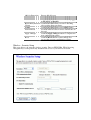
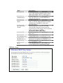
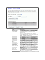
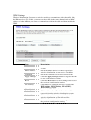
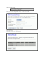
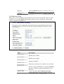
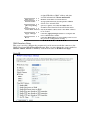
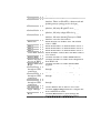
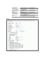
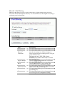
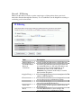
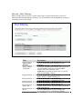
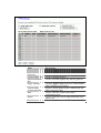
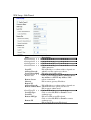
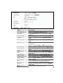
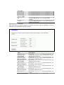
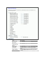
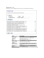
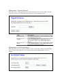
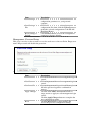
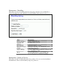
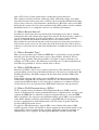
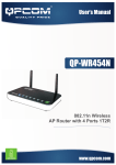
EZStation2
User Manual
Rev. A
2.4GHz 400mW 802.11b/g Radio
with 15dBi Patch Antenna
Disclaimers
No part of this documentation may be reproduced in any form or by any means or used to make any derivative work (such as
translation, transformation or adaptation) without written permission from the copyright owner.
All other trademarks and registered trademarks are the property of their respective owners.
Statement of Conditions
We may make improvements or changes in the product described in this documentation at any time. The information
regarding the product in this manual is subject to change without notice.
We assume no responsibility for errors contained herein or for direct, indirect, special, incidental or consequential damages
with the furnishing, performance or use of this manual or equipment supplied with it, even if the suppliers have been advised
about the possibility of such damages.
Electronic Emission Notices
This device complies with Part 15 of the FCC Rules. Operation is subject to the following two conditions:
(1)This device may not cause harmful interference.
(2)This device must accept any interference received, including interference that may cause undesired operation.
FCC INFORMATION
The Federal Communication Commission Radio Frequency Interference Statement includes the following paragraph:
The equipment has been tested and found to comply with the limits for a Class B Digital Device, pursuant to part 15 of the
FCC Rules. These limits are designed to provide reasonable protection against harmful interference in a residential
installation. This equipment usage generates radio frequency energy and, if not installed and used in accordance with the
instructions, may cause harmful interference to radio communication. However, there is no grantee that interference will not
occur in a particular installation. If this equipment does cause harmful interference to radio or television reception, which can
be determined by turning the equipment off and on, the user is encouraged to try to correct the interference by one or more of
the following measures:
•
Reorient or relocate the receiving antenna.
•
Increase the separation between the equipment and receiver.
•
Connect the equipment into an outlet on a circuit different from that to which the receiver is connected.
•
Consult the dealer or an experienced radio/TV technician for help.
The equipment is for home or office use.
IMPORTANT NOTE
FCC RF Radiation Exposure Statement: This equipment complies with FCC RF radiation exposure limits set forth for an
uncontrolled environment. This equipment should be installed and operated with a minimum distance of 20cm between the
antenna and your body and must not be co-located or operating in conjunction with any other antenna or transmitter.
Caution: Changes or modifications not expressly approved by the party responsible for compliance could
void the user's authority to operate the equipment.
Before Start to Configure
The WLAN Broadband Router is delivered with the following factory
default parameters on the Ethernet LAN interfaces.
Default IP Address: 192.168.1.254
Default IP subnet mask: 255.255.255.0
WEB login User Name: <empty>
WEB login Password: <empty>
The device has three operation modes (Gateway/Bridge/WISP).
The default IP addresses for the device are 192.168.1.254, so you
need to make sure the IP address of your PC is in the same subnet as
the device, such as 192.168.1.X.
It will take about 55 seconds to complete the boot up sequence
after power on.
Prepare your PC to configure the WLAN Broadband Router
For OS of Microsoft Windows 95/ 98/ Me:
1. Click the Start button and select Settings, then click Control Panel. The
Control Panel window will appear.
Note: Windows Me users may not see the Network control panel. If so,
select View all Control Panel options on the left side of the window
2. Move mouse and double-click the right button on Network icon. The
Network window will appear.
3. Check the installed list of Network Components. If TCP/IP is not installed,
click the Add button to install it; otherwise go to step 6.
4. Select Protocol in the Network Component Type dialog box and click Add
button.
5. Select TCP/IP in Microsoft of Select Network Protocol dialog box then
click OK button to install the TCP/IP protocol, it may need the Microsoft
Windows CD to complete the installation. Close and go back to Network
dialog box after the TCP/IP installation.
6. Select TCP/IP and click the properties button on the Network dialog box.
7. Select Specify an IP address and type in values as following example.
IP Address: 192.168.1.1, any IP address within 192.168.1.1 to
192.168.1.253 is good to connect the Wireless LAN Access Point.
IP Subnet Mask: 255.255.255.0
8. Click OK and reboot your PC after completes the IP parameters setting.
For OS of Microsoft Windows 2000, XP:
1. Click the Start button and select Settings, then click Control Panel. The
Control Panel window will appear.
2. Move mouse and double-click the right button on Network and Dial-up
Connections icon. Move mouse and double-click the Local Area
Connection icon. The Local Area Connection window will appear. Click
Properties button in the Local Area Connection window.
3. Check the installed list of Network Components. If TCP/IP is not installed,
click the Add button to install it; otherwise go to step 6.
4. Select Protocol in the Network Component Type dialog box and click Add
button.
5. Select TCP/IP in Microsoft of Select Network Protocol dialog box then
click OK button to install the TCP/IP protocol, it may need the Microsoft
Windows CD to complete the installation. Close and go back to Network
dialog box after the TCP/IP installation.
6. Select TCP/IP and click the properties button on the Network dialog box.
7. Select Specify an IP address and type in values as following example.
IP Address: 192.168.1.1, any IP address within 192.168.1.1 to
192.168.1.253 is good to connect the Wireless LAN Access Point.
IP Subnet Mask: 255.255.255.0
8. Click OK to completes the IP parameters setting.
For OS of Microsoft Windows NT:
1. Click the Start button and select Settings, then click Control Panel. The
Control Panel window will appear.
2. Move mouse and double-click the right button on Network icon. The
Network window will appear. Click Protocol tab from the Network window.
3. Check the installed list of Network Protocol window. If TCP/IP is not
installed, click the Add button to install it; otherwise go to step 6.
4. Select Protocol in the Network Component Type dialog box and click Add
button.
5. Select TCP/IP in Microsoft of Select Network Protocol dialog box then
click OK button to install the TCP/IP protocol, it may need the Microsoft
Windows CD to complete the installation. Close and go back to Network
dialog box after the TCP/IP installation.
6. Select TCP/IP and click the properties button on the Network dialog box.
7. Select Specify an IP address and type in values as following example.
IP Address: 192.168.1.1, any IP address within 192.168.1.1 to
192.168.1.253 is good to connect the Wireless LAN Access Point.
IP Subnet Mask: 255.255.255.0
8. Click OK to complete the IP parameters setting.
This page shows the current status and some basic settings of the device,
includes system, wireless, Ethernet LAN and WAN configuration
information.
Item
System
Uptime
Description
It shows the duration since WLAN Broadband
Firmware version
Router is powered on.
It shows the firmware version of WLAN
Broadband Router.
Wireless configuration
Mode
It shows wireless operation mode
Band
It shows the current wireless operating
frequency.
SSID
It shows the SSID of this WLAN Broadband
Router.
The SSID is the unique name of WLAN
Broadband Router and shared among its service
area, so all devices attempts to join the same
wireless network can identify it.
Channel Number
It shows the wireless channel connected
currently.
Encryption
It shows the status of encryption function.
BSSID
It shows the BSSID address of the WLAN
Broadband Router. BSSID is a six-byte address.
Associated Clients
It shows the number of connected clients (or
stations, PCs).
TCP/IP configuration
Attain IP Protocol
It shows type of connection.
IP Address
It shows the IP address of LAN interfaces of
WLAN Broadband Router.
Subnet Mask
It shows the IP subnet mask of LAN interfaces
of WLAN Broadband Router.
Default Gateway
It shows the default gateway setting for LAN
interfaces outgoing data packets.
DHCP Server
It shows the DHCP server is enabled or not.
MAC Address
It shows the MAC address of LAN interfaces of
WLAN Broadband Router.
WAN configuration
Attain IP Protocol
It shows how the WLAN Broadband Router gets
the IP address. The IP address can be set
manually to a fixed one or set dynamically by
DHCP server or attain IP by PPPoE / PPTP
connection.
IP Address
It shows the IP address of WAN interface of
WLAN Broadband Router.
Subnet Mask
It shows the IP subnet mask of WAN interface of
WLAN Broadband Router.
Default Gateway
It shows the default gateway setting for WAN
interface outgoing data packets.
DNS1/DNS2/DNS3
It shows the DNS server information.
MAC Address
It shows the MAC address of WAN interface of
WLAN Broadband Router.
Setup Wizard
This page guides you to configure wireless broadband router for first time
Operation Mode
This page followed by Setup Wizard page to define the operation mode.
Time Zone Setting
This page is used to enable and configure NTP client
LAN Interface Setup
This page is used to configure local area network IP address and subnet mask
WAN Interface Setup
This page is used to configure WAN access type
Wireless Basic Settings
This page is used to configure basic wireless parameters like Band, Mode, Network Type
SSID, Channel Number, Enable Mac Clone(Single Ethernet Client)
Wireless Security Setup
This page is used to configure wireless security
Operation Mode
This page is used to configure which mode wireless broadband router acts
Item
Gateway
Bridge
Wireless ISP
Apply Changes
Reset
Description
Traditional gateway configuration. It always
connects internet via ADSL/Cable Modem. LAN
interface, WAN interface, Wireless interface, NAT
and Firewall modules are applied to this mode
Each interface (LAN, WAN and Wireless) regards
as bridge. NAT, Firewall and all router’s functions
are not supported
Switch Wireless interface to WAN port and all
Ethernet ports in bridge mode. Wireless interface
can do all router’s functions
Click the Apply Changes button to complete the
new configuration setting.
Click the Reset button to abort change and recover
the previous configuration setting.
Wireless - Basic Settings
This page is used to configure the parameters for wireless LAN clients that may connect
to your Broadband Router. Here you may change wireless encryption settings as well as
wireless network parameters.
Item
Disable Wireless
LAN Interface
Band
Mode
Site Survey
SSID
Channel Number
Associated Clients
Enable Mac Clone
(Single Ethernet
Client)
Enable Universal
Repeater Mode
SSID of Extended
Interface
Apply Changes
Reset
Description
Click on to disable the wireless LAN data
transmission.
Click to select 2.4GHz(B) / 2.4GHz(G) /
2.4GHz(B+G)
Click to select the WLAN AP / Client / WDS /
AP+WDS wireless mode.
The Site Survey button provides tool to scan the
wireless network. If any Access Point or IBSS is
found, you could choose to connect it manually
when client mode is enabled. Refer to 3.3.9 Site
Survey.
It is the wireless network name. The SSID can be
32 bytes long.
Select the wireless communication channel from
pull-down menu.
Click the Show Active Clients button to open
Active Wireless Client Table that shows the MAC
address, transmit-packet, receive-packet and
transmission-rate for each associated wireless
client.
Take Laptop NIC MAC address as wireless client
MAC address. [Client Mode only]
Click to enable Universal Repeater Mode
Assign SSID when enables Universal Repeater
Mode.
Click the Apply Changes button to complete the
new configuration setting.
Click the Reset button to abort change and recover
the previous configuration setting.
Wireless - Advanced Settings
These settings are only for more technically advanced users who have a sufficient
knowledge about wireless LAN. These settings should not be changed unless you know
what effect the changes will have on your WLAN Broadband Router.
Item
Authentication Type
Fragment Threshold
RTS Threshold
Beacon Interval
Data Rate
Preamble Type
Broadcast SSID
IAPP
Description
Click to select the authentication type in Open
System, Shared Key or Auto selection.
Set the data packet fragmentation threshold, value
can be written between 256 and 2346 bytes.
Set the RTS Threshold, value can be written
between 0 and 2347 bytes.
Set the Beacon Interval, value can be written
between 20 and 1024 ms.
Select the transmission data rate from pull-down
menu. Data rate can be auto-select, 11M, 5.5M,
2M or 1Mbps.
Click to select the Long Preamble or Short
Preamble support on the wireless data packet
transmission.
Click to enable or disable the SSID broadcast
function.
Click to enable or disable the IAPP function.
802.11g Protection
RF Output Power
Turbo Mode
Protect 802.11b user.
To adjust transmission power level.
Click to Enable/Disable turbo mode.(Only apply
to WLAN IC of Realtek).
Block Relay Between Click Enabled/Disabled to decide if blocking
Clients
relay packets between clients.
WMM
Click Enabled/Disabled to init WMM feature.
ACK Timeout
Set ACK timeout value. It shows current time in
the end.
Apply Changes
Click the Apply Changes button to complete the
new configuration setting.
Reset
Click the Reset button to abort change and
recover the previous configuration setting.
Wireless - Security Setup
This page allows you setup the wireless security. Turn on WEP, WPA, WPA2 by using
encryption keys could prevent any unauthorized access to your wireless network.
Item
Encryption
Use 802.1x
Authentication
WPA Authentication
Mode
Pre-Shared Key
Format
Pre-Shared Key
Enable
Pre-Authentication
Authentication
RADIUS Server
Apply Changes
Reset
WEP Key Setup
Description
Select the encryption supported over wireless
access. The encryption method can be None,
WEP, WPA(TKIP), WPA2 or WPA2 Mixed
While Encryption is selected to be WEP.
Click the check box to enable IEEE 802.1x
authentication function.
While Encryption is selected to be WPA.
Click to select the WPA Authentication Mode
with Enterprise (RADIUS) or Personal
(Pre-Shared Key).
While Encryption is selected to be WPA.
Select the Pre-shared key format from the
pull-down menu. The format can be Passphrase
or Hex (64 characters). [WPA,
Personal(Pre-Shared Key) only]
Fill in the key value. [WPA, Personal(Pre-Shared
Key) only]
Click to enable Pre-Authentication.
[WPA2/WPA2 Mixed only, Enterprise only]
Set the IP address, port and login password
information of authentication RADIUS sever.
Click the Apply Changes button to complete the
new configuration setting.
Click the Reset button to abort change and
recover the previous configuration setting.
Item
Key Length
Key Format
Default Tx Key
Encryption Key 1
Encryption Key 2
Encryption Key 3
Encryption Key 4
Apply Changes
Close
Reset
Description
Select the WEP shared secret key length from
pull-down menu. The length can be chose
between 64-bit and 128-bit (known as “WEP2”)
keys.
The WEP key is composed of initialization vector
(24 bits) and secret key (40-bit or 104-bit).
Select the WEP shared secret key format from
pull-down menu. The format can be chose
between plant text (ASCII) and hexadecimal
(HEX) code.
Set the default secret key for WEP security
function.
Value can be chose between 1 and 4.
Secret key 1 of WEP security encryption function.
Secret key 2 of WEP security encryption function.
Secret key 3 of WEP security encryption function.
Secret key 4 of WEP security encryption function.
Click the Apply Changes button to complete the
new configuration setting.
Click to close this WEP Key setup window.
Click the Reset button to abort change and
recover the previous configuration setting.
WEP encryption key (secret key) length:
Length
64-bit
Format
ASCII
HEX
5 characters
10 hexadecimal codes
128-bit
13 characters
26 hexadecimal codes
Wireless - Access Control
If you enable wireless access control, only those clients whose wireless MAC addresses
are in the access control list will be able to connect to your Access Point. When this
option is enabled, no wireless clients will be able to connect if the list contains no entries.
Item
Wireless Access
Control Mode
MAC Address
Comment
Apply Changes
Reset
Current Access
Control List
Delete Selected
Delete All
Reset
Description
Click the Disabled, Allow Listed or Deny Listed
of drop down menu choose wireless access
control mode.
This is a security control function; only those
clients registered in the access control list can link
to this WLAN Broadband Router.
Fill in the MAC address of client to register this
WLAN Broadband Router access capability.
Fill in the comment tag for the registered client.
Click the Apply Changes button to register the
client to new configuration setting.
Click the Reset button to abort change and recover
the previous configuration setting.
It shows the registered clients that are allowed to
link to this WLAN Broadband Router.
Click to delete the selected clients that will be
access right removed from this WLAN Broadband
Router.
Click to delete all the registered clients from the
access allowed list.
Click the Reset button to abort change and recover
the previous configuration setting.
WDS Settings
Wireless Distribution System uses wireless media to communicate with other APs, like
the Ethernet does. To do this, you must set these APs in the same channel and set MAC
address of other AP that you want to communicate with in the table and then enable the
WDS.
Item
Enable WDS
MAC Address
Comment
Apply Changes
Reset
Set Security
Show Statistics
Delete Selected
Delete All
Reset
Description
Click the check box to enable wireless distribution
system.
Fill in the MAC address of AP to register the
wireless distribution system access capability.
Fill in the comment tag for the registered AP.
Click the Apply Changes button to register the AP
to new configuration setting.
Click the Reset button to abort change and recover
the previous configuration setting.
Click button to configure wireless security like
WEP(64bits), WEP(128bits), WPA(TKIP),
WPA2(AES) or None
It shows the TX, RX packets, rate statistics
Click to delete the selected clients that will be
removed from the wireless distribution system.
Click to delete all the registered APs from the
wireless distribution system allowed list.
Click the Reset button to abort change and recover
the previous configuration setting.
WDS Security Setup
Requirement: Set [Wireless]->[Basic
Settings]->[Mode]->AP+WDS
This page is used to configure the wireless security between APs.
WDS AP Table
This page is used to show WDS statistics
Item
MAC Address
Tx Packets
Tx Errors
Rx Packets
Tx Rare (Mbps)
Refresh
Close
Description
It shows the MAC Address within WDS.
It shows the statistic count of sent packets on the
wireless LAN interface.
It shows the statistic count of error sent packets on
the Wireless LAN interface.
It shows the statistic count of received packets on
the wireless LAN interface.
It shows the wireless link rate within WDS.
Click to refresh the statistic counters on the
screen.
Click to close the current window.
Site Survey
This page is used to view or configure other APs near yours.
Item
SSID
BSSID
Channel
Type
Encrypt
Signal
Select
Description
It shows the SSID of AP.
It shows BSSID of AP.
It show the current channel of AP occupied.
It show which type AP acts.
It shows the encryption status.
It shows the power level of current AP.
Click to select AP or client you’d like to connect.
Refresh
Connect
Click the Refresh button to re-scan site survey on
the screen.
Click the Connect button to establish connection.
LAN Interface Setup
This page is used to configure the parameters for local area network that connects to the
LAN ports of your WLAN Broadband Router. Here you may change the setting for IP
address, subnet mask, DHCP, etc.
Item
IP Address
Description
Fill in the IP address of LAN interfaces of this
WLAN Access Point.
Subnet Mask
Fill in the subnet mask of LAN interfaces of this
WLAN Access Point.
Default Gateway
Fill in the default gateway for LAN interfaces out
going data packets.
DHCP
Click to select Disabled, Client or Server in
different operation mode of wireless Access Point.
DHCP Client Range Fill in the start IP address and end IP address to
allocate a range of IP addresses; client with DHCP
function set will be assigned an IP address from
the range.
Show Client
Click to open the Active DHCP Client Table
window that shows the active clients with their
assigned IP address, MAC address and time
expired information. [Server mode only]
DNS Server
Manual setup DNS server IP address.
Domain Name
Assign Domain Name and dispatch to DHCP
clients. It is optional field.
802.1d Spanning
Select to enable or disable the IEEE 802.1d
Tree
Spanning Tree function from pull-down menu.
Clone MAC Address Fill in the MAC address that is the MAC address
to be cloned.
Apply Changes
Click the Apply Changes button to complete the
new configuration setting.
Reset
Click the Reset button to abort change and recover
the previous configuration setting.
WAN Interface Setup
This page is used to configure the parameters for wide area network that connects to the
WAN port of your WLAN Broadband Router. Here you may change the access method to
Static IP, DHCP, PPPoE or PPTP by click the item value of WAN Access Type.
Static IP
Item
Static IP
Description
Click to select Static IP support on WAN
interface. There are IP address, subnet mask and
default gateway settings need to be done.
IP Address
If you select the Static IP support on WAN
interface, fill in the IP address for it.
Subnet Mask
If you select the Static IP support on WAN
interface, fill in the subnet mask for it.
Default Gateway
If you select the Static IP support on WAN
interface, fill in the default gateway for WAN
interface out going data packets.
MTU Size
Fill in the mtu size of MTU Size. The default
value is 1400
DNS 1
Fill in the IP address of Domain Name Server 1.
DNS 2
Fill in the IP address of Domain Name Server 2.
DNS 3
Fill in the IP address of Domain Name Server 3.
Clone MAC Address Fill in the MAC address that is the MAC address
to be cloned.
Enable uPNP
Click the checkbox to enable uPNP function.
Enable Web Server Click the checkbox to enable web configuration
Access on WAN
from WAN side.
Enable WAN Echo Click the checkbox to enable WAN ICMP
Reply
response.
Enable IPsec pass
Click the checkbox to enable IPSec packet pass
through on VPN
through
connection
Enable PPTP pass
Click the checkbox to enable PPTP packet pass
through on VPN
through
connection
Enable L2TP pass
Click the checkbox to enable L2TP packet pass
through on VPN
through
connection
Set TTL value
Click to Enable and set Time to Live value.
Apply Changes
Click the Apply Changes button to complete the
new configuration setting.
Reset
Click the Reset button to abort change and
recover the previous configuration setting.
DHCP Client
Item
DHCP Client
Description
Click to select DHCP support on WAN interface
for IP address assigned automatically from a
DHCP server.
Host Name
Fill in the host name of Host Name. The default
value is empty
MTU Size
Fill in the mtu size of MTU Size. The default
value is 1400
Attain DNS
Click to select getting DNS address for DHCP
Automatically
support. Please select Set DNS Manually if the
DHCP support is selected.
Set DNS Manually
Click to select getting DNS address for DHCP
support.
DNS 1
Fill in the IP address of Domain Name Server 1.
DNS 2
Fill in the IP address of Domain Name Server 2.
DNS 3
Fill in the IP address of Domain Name Server 3.
Clone MAC Address Fill in the MAC address that is the MAC address
to be cloned.
Enable uPNP
Click the checkbox to enable uPNP function.
Enable Web Server
Access on WAN
Enable WAN Echo
Reply
Set TTL value
Apply Changes
Reset
PPPoE
Refer to 4.22 What is Universal Plug and Play
(uPNP)?
Click the checkbox to enable web configuration
from WAN side.
Click the checkbox to enable WAN ICMP
response.
Click to Enable and set Time to Live value.
Click the Apply Changes button to complete the
new configuration setting.
Click the Reset button to abort change and
recover the previous configuration setting.
Item
PPPoE
Description
Click to select PPPoE support on WAN interface.
There are user name, password, connection type
and idle time settings need to be done.
User Name
If you select the PPPoE support on WAN
interface, fill in the user name and password to
login the PPPoE server.
Password
If you select the PPPoE support on WAN
interface, fill in the user name and password to
login the PPPoE server.
Service Name
Fill in the service name of Service Name. The
default value is empty.
Connection Type
Select the connection type from pull-down menu.
There are Continuous, Connect on Demand and
Manual three types to select.
Continuous connection type means to setup the
connection through PPPoE protocol whenever
this WLAN Broadband Router is powered on.
Connect on Demand connection type means to
setup the connection through PPPoE protocol
whenever you send the data packets out through
the WAN interface; there are a watchdog
implemented to close the PPPoE connection
while there are no data sent out longer than the
idle time set.
Manual connection type means to setup the
connection through the PPPoE protocol by
clicking the Connect button manually, and
clicking the Disconnect button manually.
Idle Time
If you select the PPPoE and Connect on
Demand connection type, fill in the idle time for
auto-disconnect function. Value can be between 1
and 1000 minutes.
MTU Size
Fill in the mtu size of MTU Size. The default
value is 1400.
Attain DNS
Click to select getting DNS address for PPPoE
Automatically
support. Please select Set DNS Manually if the
PPPoE support is selected.
Set DNS Manually
Click to select getting DNS address for Static IP
support.
DNS 1
Fill in the IP address of Domain Name Server 1.
DNS 2
Fill in the IP address of Domain Name Server 2.
DNS 3
Fill in the IP address of Domain Name Server 3.
Clone MAC Address Fill in the MAC address that is the MAC address
to be cloned.
Enable uPNP
Enable Web Server
Access on WAN
Enable WAN Echo
Reply
Set TTL value
Apply Changes
Reset
PPTP
Click the checkbox to enable uPNP function.
Click the checkbox to enable web configuration
from WAN side.
Click the checkbox to enable WAN ICMP
response.
Click to Enable and set Time to Live value.
Click the Apply Changes button to complete the
new configuration setting.
Click the Reset button to abort change and
recover the previous configuration setting.
Item
PPTP
Description
Allow user to make a tunnel with remote site
directly to secure the data transmission among the
connection. User can use embedded PPTP client
supported by this router to make a VPN
connection.
IP Address
If you select the PPTP support on WAN interface,
fill in the IP address for it.
Subnet Mask
If you select the PPTP support on WAN interface,
fill in the subnet mask for it.
Server IP Address
Enter the IP address of the PPTP Server.
User Name
If you select the PPTP support on WAN interface,
fill in the user name and password to login the
PPTP server.
Password
f you select the PPTP support on WAN interface,
fill in the user name and password to login the
PPTP server.
MTU Size
Fill in the mtu size of MTU Size. The default
value is 1400.
Request MPPE
Click the checkbox to enable request MPPE
Encryption
encryption.
Attain DNS
Click to select getting DNS address for PPTP
Automatically
support. Please select Set DNS Manually if the
PPTP support is selected.
Set DNS Manually
Click to select getting DNS address for PPTP
support.
DNS 1
Fill in the IP address of Domain Name Server 1.
DNS 2
Fill in the IP address of Domain Name Server 2.
DNS 3
Fill in the IP address of Domain Name Server 3.
Clone MAC Address Fill in the MAC address that is the MAC address
to be cloned.
Enable uPNP
Click the checkbox to enable uPNP function.
Enable Web Server
Click the checkbox to enable web configuration
Access on WAN
from WAN side.
Enable WAN Echo
Click the checkbox to enable WAN ICMP
Reply
response.
Set TTL value
Click to Enable and set Time to Live value.
Apply Changes
Click the Apply Changes button to complete the
new configuration setting.
Reset
Click the Reset button to abort change and
recover the previous configuration setting.
Firewall - Port Filtering
Entries in this table are used to restrict certain types of data packets from your local
network to Internet through the Gateway. Use of such filters can be helpful in securing or
restricting your local network.
Item
Enable Port Filtering
Port Range
Protocol
Comments
Apply Changes
Reset
Delete Selected
Delete All
Reset
Description
Click to enable the port filtering security function.
To restrict data transmission from the local
network on certain ports, fill in the range of
start-port and end-port, and the protocol, also put
your comments on it.
The Protocol can be TCP, UDP or Both.
Comments let you know about whys to restrict
data from the ports.
Click the Apply Changes button to register the
ports to port filtering list.
Click the Reset button to abort change and
recover the previous configuration setting.
Click to delete the selected port range that will be
removed from the port-filtering list.
Click to delete all the registered entries from the
port-filtering list.
Click the Reset button to abort change and
recover the previous configuration setting.
Firewall - IP Filtering
Entries in this table are used to restrict certain types of data packets from your local
network to Internet through the Gateway. Use of such filters can be helpful in securing or
restricting your local network.
Item
Enable IP Filtering
Local IP Address
Protocol
Comments
Apply Changes
Reset
Delete Selected
Delete All
Reset
Description
Click to enable the IP filtering security function.
To restrict data transmission from local network
on certain IP addresses, fill in the IP address and
the protocol, also put your comments on it.
The Protocol can be TCP, UDP or Both.
Comments let you know about whys to restrict
data from the IP address.
Click the Apply Changes button to register the IP
address to IP filtering list.
Click the Reset button to abort change and
recover the previous configuration setting.
Click to delete the selected IP address that will be
removed from the IP-filtering list.
Click to delete all the registered entries from the
IP-filtering list.
Click the Reset button to abort change and
recover the previous configuration setting.
Firewall - MAC Filtering
Entries in this table are used to restrict certain types of data packets from your local
network to Internet through the Gateway. Use of such filters can be helpful in securing or
restricting your local network.
Item
Enable MAC
Filtering
MAC Address
Comments
Apply Changes
Reset
Delete Selected
Delete All
Reset
Description
Click to enable the MAC filtering security
function.
To restrict data transmission from local network
on certain MAC addresses, fill in the MAC
address and your comments on it.
Comments let you know about whys to restrict
data from the MAC address.
Click the Apply Changes button to register the
MAC address to MAC filtering list.
Click the Reset button to abort change and
recover the previous configuration setting.
Click to delete the selected MAC address that will
be removed from the MAC-filtering list.
Click to delete all the registered entries from the
MAC-filtering list.
Click the Reset button to abort change and
recover the previous configuration setting.
Firewall - Port Forwarding
Entries in this table allow you to automatically redirect common network services to a
specific machine behind the NAT firewall. These settings are only necessary if you wish
to host some sort of server like a web server or mail server on the private local network
behind your Gateway's NAT firewall.
Item
Enable Port
Forwarding
IP Address
Protocol
Port Range
Comment
Apply Changes
Reset
Description
Click to enable the Port Forwarding security
function.
To forward data packets coming from WAN to a
specific IP address that hosted in local network
behind the NAT firewall, fill in the IP address,
protocol, port range and your comments.
The Protocol can be TCP, UDP or Both.
The Port Range for data transmission.
Comments let you know about whys to allow data
packets forward to the IP address and port
number.
Click the Apply Changes button to register the IP
address and port number to Port forwarding list.
Click the Reset button to abort change and
recover the previous configuration setting.
Delete Selected
Delete All
Reset
Click to delete the selected IP address and port
number that will be removed from the
port-forwarding list.
Click to delete all the registered entries from the
port-forwarding list.
Click the Reset button to abort change and
recover the previous configuration setting.
Firewall – URL Filtering
URL Filtering is used to restrict users to access specific websites in internet.
Item
Enable URL
Filtering
URL Address
Apply Changes
Reset
Delete Selected
Delete All
Reset
Description
Click to enable the URL Filtering function.
Add one URL address.
Click the Apply Changes button to save settings.
Click the Reset button to abort change and recover
the previous configuration setting.
Click to delete the selected URL address that will
be removed from the URL Filtering list.
Click to delete all the registered entries from the
URL Filtering list.
Click the Reset button to abort change and recover
the previous configuration setting.
Firewall - DMZ
A Demilitarized Zone is used to provide Internet services without sacrificing
unauthorized access to its local private network. Typically, the DMZ host contains
devices accessible to Internet traffic, such as Web (HTTP) servers, FTP servers, SMTP
(e-mail) servers and DNS servers.
Item
Enable DMZ
DMZ Host IP
Address
Description
Click to enable the DMZ function.
To support DMZ in your firewall design, fill in the
IP address of DMZ host that can be access from
the WAN interface.
Apply Changes
Click the Apply Changes button to register the IP
address of DMZ host.
Click the Reset button to abort change and recover
the previous configuration setting.
Reset
VPN Setting
This page is used to show VPN connection table, configure IPSEC VPN, NAT Traversal,
Generate RSA Key, Show RSA Public Key.
Item
Enable IPSEC VPN
Enable NAT
Traversal
Generate RSA Key
Show RSA Public
Key
Apply Changes
Current VPN
Connection Table
Edit
Delete
Refresh
Description
Click to enable IPSEC VPN function.
Click to enable NAT Traversal function.
Click to generate RSA key.
Click to show RSA public key that we generate.
Click the Apply Changes button to enable IPSEC
VPN, NAT Traversal settings.
It shows current WAN interface information and
VPN connection table.
Click to enter the current VPN tunnel
configuration page.
Click to delete the current VPN tunnel that radio
button stay.
Click to refresh the current VPN connection table.
VPN Setup - Edit Tunnel
Item
Enable Tunnel #
Connection Name
Auth Type
Local Site
Local IP
Address/Network
Local Subnet Mask
Remote Site
Description
Click to enable the IPSEC VPN current tunnel.
Assign the connection name tag.
Click to select PSK or RSA.
Click to select Single Address or Subnet Address
VPN connection.
Fill in IP address or subnet address depends on
which Local Site option you choose.
Fill in the local subnet mask.
Click to select Single Address, Subnet Address,
Any Address or NAT-T Any Address VPN
remote connection.
Fill in remote gateway IP address
Remote Secure
Gateway
Remote IP
Fill in IP address or subnet address depends on
Address/Network
Remote Subnet Mask which Remote Site option you choose.
Fill in remote subnet mask
Local/Peer ID
Define IKE exchange information type
Click to select IP, DNS or E-mail as local
Local ID Type
exchange type
Local ID
Fill in local ID except IP selected
Remote ID Type
Click to select IP, DNS or E-mail as remote
exchange type
Remote ID
Fill in remote ID except IP selected
Item
Key Management
Advanced
Connection Type
Connect
Disconnect
ESP
PreShared Key
Remote RSA Key
Status
SPI
Encryption Key
Authentication Key
Apply Change
Reset
Refresh
Back
Description
Click to select IKE or Manual mode.
Click Advanced button to configure more IKE
settings.
Click to select Initiator or Responder mode.
Click to connect manually. [Responder mode
only]
Click to disconnect manually. [Responder mode
only].
Click to configure 3DES, AES128 or NULL
encryption.
Click to configure MD5 or SHA1 authentication.
Fill in the key value. [IKE mode only]
Fill in the remote gateway RSA key. [IKE mode
only]
It shows connection status. [IKE mode only]
Fill in Security Parameter Index value. [Manual
mode only]
Fill in encryption key. [Manual mode only]
Fill in authentication key. [Manual mode only]
Click the Apply Changes button to save current
tunnel settings.
Click the Reset button to abort change and
recover the previous configuration setting.
It shows the current connection status. [Manual
mode only]
It returns back to VPN Setup page.
Advanced IKE Setup
Item
Phase 1
Negotiation Mode
Encryption Algorithm
Authentication
Algorithm
Key Group
Description
Main mode.
Click to select 3DES or AES128 encryption.
Click to select MD5 or SHA1 authentication.
Click to select DH1(modp768), DH2(modp1024)
or DH5(modp1536) key group. Default value is
DH2
Fill in the key life time value by seconds.
Key Life Time
Phase 2
Active Protocol
ESP.
Encryption Algorithm Click to select 3DES, AES128 or NULL
encryption.
Authentication
Click to select MD5 or SHA1 authentication.
Algorithm
Key Life Time
Encapsulation
Perfect Forward
Secrecy (PFS)
Ok
Cancel
Fill in the key life time value by seconds.
Tunnel mode.
Click to select ON or NONE.
Click the Ok button to save current tunnel
settings.
Click the Cancel button to close current window
without any changes.
Management - Statistics
This page shows the packet counters for transmission and reception regarding to wireless,
Ethernet LAN and Ethernet WAN networks.
Item
Wireless LAN
Sent Packets
Wireless LAN
Received Packets
Ethernet LAN
Sent Packets
Ethernet LAN
Received Packets
Ethernet WAN
Sent Packets
Ethernet WAN
Received Packets
Refresh
Description
It shows the statistic count of sent packets on the
wireless LAN interface.
It shows the statistic count of received packets on
the wireless LAN interface.
It shows the statistic count of sent packets on the
Ethernet LAN interface.
It shows the statistic count of received packets on
the Ethernet LAN interface.
It shows the statistic count of sent packets on the
Ethernet WAN interface.
It shows the statistic count of received packets on
the Ethernet WAN interface.
Click the refresh the statistic counters on the
screen.
Management - DDNS
This page is used to configure Dynamic DNS service to have DNS with dynamic IP
address.
Item
Enable DDNS
Service Provider
Domain Name
User Name/Email
Password/Key
Apply Change
Reset
Description
Click the checkbox to enable DDNS service.
Click the drop down menu to pickup the right
provider.
To configure the Domain Name.
Configure User Name, Email.
Configure Password, Key.
Click the Apply Changes button to save the
enable DDNS service.
Click the Reset button to abort change and
recover the previous configuration setting.
Management - Time Zone Setting
This page is used to configure NTP client to get current time.
Item
Current Time
Time Zone Select
Enable NTP client
update
NTP Server
Apply Change
Reset
Refresh
Description
It shows the current time.
Click the time zone in your country.
Click the checkbox to enable NTP client update. R
Click select default or input NTP server IP
address.
Click the Apply Changes button to save and
enable NTP client service.
Click the Reset button to abort change and recover
the previous configuration setting.
Click the refresh the current time shown on the
screen.
Management – Denial-of-Service
This page is used to enable and setup protection to prevent attack by hacker’s program. It
provides more security for users.
Item
Enable DoS
Prevention
Whole System Flood
/ Per-Source IP
Flood…
Select ALL
Clear ALL
Apply Changes
Description
Click the checkbox to enable DoS prevention.
Enable and setup prevention in details.
Click the checkbox to enable all prevention items.
Click the checkbox to disable all prevention
items.
Click the Apply Changes button to save above
settings.
Management - Log
This page is used to configure the remote log server and shown the current log.
Item
Enable Log
System all
Wirelessy
DoS
Enable Remote Log
Log Server IP
Address
Apply Changes
Refresh
Clear
Description
Click the checkbox to enable log.
Show all log of wireless broadband router
Only show wireless log
Only show Denial-of-Service log
Click the checkbox to enable remote log service.
Input the remote log IP address
Click the Apply Changes button to save above
settings.
Click the refresh the log shown on the screen.
Clear log display screen
Management - Upgrade Firmware
This page allows you upgrade the Access Point firmware to new version. Please note, do
not power off the device during the upload because it may crash the system.
Item
Select File
Upload
Reset
Description
Click the Browse button to select the new version
of web firmware image file.
Click the Upload button to update the selected
web firmware image to the WLAN Broadband
Router.
Click the Reset button to abort change and recover
the previous configuration setting.
Management Save/ Reload Settings
This page allows you save current settings to a file or reload the settings from the file that
was saved previously. Besides, you could reset the current configuration to factory
default.
Item
Description
Save Settings to File Click the Save button to download the
configuration parameters to your personal
computer.
Load Settings from Click the Browse button to select the
File
configuration files then click the Upload button to
update the selected configuration to the WLAN
Broadband Router.
Reset Settings to
Click the Reset button to reset the configuration
Default
parameter to factory defaults.
Management - Password Setup
This page is used to set the account to access the web server of Access Point. Empty user
name and password will disable the protection.
+
Item
User Name
Description
Fill in the user name for web management login
control.
New Password
Fill in the password for web management login
control.
Confirmed Password Because the password input is invisible, so please
fill in the password again for confirmation
purpose.
Apply Changes
Clear the User Name and Password fields to
empty, means to apply no web management login
control.
Click the Apply Changes button to complete the
new configuration setting.
Reset
Click the Reset button to abort change and
recover the previous configuration setting.
Management - WatchDog
This page is used to do watchdog function using ping command. User set IP address,
interval and ping fail count conditions to decide whether router reboots or not.
Item
Enable WatchDog
WatchDog IP
Address
Ping Interval
Ping Fail to reboot
Count
Apply Changes
Reset
Description
Click to enable watchdog.
IP address that is referred.
Fill in the value by seconds.
Fill in the value that is the threshold to reboot
router when ping fails.
Click the Apply Changes button to complete the
new configuration setting.
Click the Reset button to abort change and
recover the previous configuration setting.
Management - Quality of Service
This page is used to do bandwidth control by ip address. User sets total and undefined
bandwidth first. Then set bandwidth by range of ip addresses.
Item
Enable QoS
ISP Bandwidth
Download
Upload
Description
Click to enable QoS.
Fill in the value that is the download stream from
ISP by KB/s.
Fill in the value that is the upload stream from ISP
by KB/s.
Undef IP Bandwidth
Download
Define the download bandwidth that is not
defined.
Upload
Define the upload bandwidth that is not defined.
Apply Changes
Click the Apply Changes button to complete the
new configuration setting.
Reset
Click the Reset button to abort change and
recover the previous configuration setting.
Item
Description
Bandwidth Control
IP Address Range
Set start and end ip address.
Guarantee Bandwidth
Download
Fill in the value by KB/s.
Upload
Fill in the value by KB/s.
Piority
Click to pick High, Medium or Low
Apply Changes
Click the Apply Changes button to complete the
new configuration setting. It is added into
Current Bandwidth Control Table.
Reset
Click the Reset button to abort change and
recover the previous configuration setting.
Delete Selected
Click to delete the selected ip addresses that will
be removed from the Current Bandwidth
Control Table.
Delete All
Click to delete all the registered entries from the
ip addresses Current Bandwidth Control Table.
Reset
Click the Reset button to abort change and
recover the previous configuration setting.
Logout
This page is used to logout web management page. This item will be activated next time
you login after you define user account and password.
Item
Apply Change
Description
Click the Apply Change button, Then click OK
button to logout.
Warranty Policy & RMA Policy
1. All Teletronics products have 1 Year Warranty Period. (Except List of Antennas Attached)
2. Our Warranty Period does not cover physical damages, misuse of the product, and natural
disasters.
3. International customers have 60 business days return policy, in order to receive full refund
for the items purchased. Only if the item is consider to be brand new unit. (Unopened
Items)
4. Domestic customers have 30 business days return policy, in order to receive full refund for
the items purchased. Only if the item is consider to be brand new unit. (Unopened Items)
5. Within the 30/60 business days, for all used items, there will be a restocking fee charge (045%). Depending on the condition of the item. Restocking Fee might vary.
6. All original materials must be returned in good resalable condition.
7. No refund, exchange or full credit will be issued after the 30/60 business day return policy.
8. Out-of Warranty items are repaired or replaced only with the customer’s prior approval.
Labor charges and freight will vary based on the condition of defective item.
9. Advanced Replacement Cases, must be issued within the 1 Year Warranty Period
10. All RMA numbers automatically expire 30 days after date of issuance.
11. Teletronics reserves the right to refuse any RMA shipment that does not come with RMA
Case Number or an invalid RMA Case Number.
Terms and Conditions
1. REPAIR WARRANTY: All warranties are void if Teletronics finds that the product has been abused, physically damaged or altered in
any way without prior written authorization. 2. OUT OF WARRANTY PRODUCT: Out-of-Warranty Products are repaired only with the
customer’s prior approval. For Out-of-Warranty repair charges, please contact us at 301.309.8500 x136 or [email protected]. 3.
PACKAGING: Please clearly mark the RMA number on the outside of the packaging. Damage or loss of goods during shipment is the
sole responsibility of the customer. Product must be returned in original carton or in packaging of equal or greater quality. 4. RMA
NUMBER: Any returned product without a valid RMA number or no RMA number will be refused and returned to the sender. RMA
numbers are only valid for 30 days from the date they are issued. Please write the RMA number on the box in bold letters using
permanent marker on at least two different sides of the box. 5. PRODUCT: Ship only the product(s) specified on the original RMA
request and includes any additional items. Any additional products will require a new RMA number. 6. SHIPPING COST: The customer is
responsible for the cost of shipment to Teletronics and we will be responsible for the cost of shipment back to the customer. Ship to:
Teletronics International, Inc. 2 Choke Cherry Road, Suite 100 Rockville, MD 20850 USA. 7. SHIPPING METHOD: All the repaired
products will be shipping back to customers via UPS/FedEX Ground service. For International customers via Economic 8. ADVANCED
REPLACEMENT: If you are requesting Advanced Replacement for the defective product, you must provide us with a valid credit card
number as a guarantee. Please Note: Advanced Replacement charges will be applied to the customer’s credit card, if the
defective product is not received by Teletronics within 21 business days. 9. RMA REFUND: Customer is required to provide the
original invoice/receipt to request RMA credit.
6-Easy Steps to Receive an RMA Case #
1.
2.
3.
4.
5.
6.
7.
Go to: http://www.teletronics.com/RMA.html
Download the RMA Form; fill it out the entire fields with the appropriate product information
Email the word file to [email protected]
Within 1 Business Day, you will receive an email with the RMA Receipt Confirmation
Package the defective unit with the suitable material
Identify the outside of the box with the RMA Case # given in the RMA Receipt
Ship the package:
Teletronics – RMA Dept
2 Choke Cherry Rd, Suite 100.
Rockville. MD – 20850
USA
NOTE: Advanced Replacement Cases must be issued before 4:30pm (Eastern Time), in order to ship
the package the same business day.
Regulatory Information
Statement of Conditions
We may make improvements or changes in the product described in this documentation at any time. The information
regarding the product in this manual are subject to change without notice.
We assume no responsibility for errors contained herein or for direct, indirect, special, incidental, or consequential
damages with the furnishing, performance or use of this manual or equipment supplied with it, even if the suppliers
have been advised of the possibility of such damages.
Electronic Emission Notices
This device complies with Part 15 of the FCC Rules. Operation is subject to the following two conditions:
(1) This device may not cause harmful interference.
(2) This device must accept any interference received, including interference that may cause undesired operation.
FCC Information
The Federal Communication Commission Radio Frequency Interference Statement includes the following paragraph:
The equipment has been tested and found to comply with the limits for a Class B Digital Device, pursuant to part 15 of
the FCC Rules. These limits are designed to provide reasonable protection against harmful interference in a residential
installation. This equipment generates, uses and can radiate radio frequency energy and if not installed and used in
accordance with instructions, may cause harmful interference to radio communication. However, there is no guarantee
that interference will not occur in a particular installation. If this equipment does cause harmful interference to radio or
television reception, which can be determined by turning the equipment off and on, the user is encouraged to try to
overcome the interference by one or more of the following measures:
-
Reorient or relocate the receiving antenna.
Increase the separation between the equipment and receiver.
Connect the equipment into an outlet on a circuit different from that to which the receiver is connected.
Consult the dealer or an experienced radio/TV technician for help.
The equipment is for home or office use.
Important Note
FCC RF Radiation Exposure Statement: This equipment complies with FCC RF radiation exposure limits set forth for
an uncontrolled environment. This equipment should be installed and operated with a minimum distance of 20cm
between the antenna and your body and must not be co-located or operated in conjunction with any other antenna or
transmitter.
Caution: Changes or modifications not expressly approved by the party responsible for compliance could void the
user's authority to operate the equipment.
R&TTE Compliance Statement
This equipment complies with all the requirements of the Directive 1999/5/EC of the European Parliament and the
Council of 9 March 1999 on radio equipment and telecommunication terminal equipment (R&TTE)and the mutual
recognition of their conformity. The R&TTE Directive repeals and replaces in the directive 98/13/EEC. As of April 8,
2000.
European Union CE Marking and Compliance Notices
Products intended for sale within the European Union are marked, which indicates compliance with the applicable
directives identified below. This equipment also carries the Class 2 identifier.
With the Conformité Européene (CE) and European standards and amendments, we declare that the equipment
described in this document is in conformance with the essential requirements of the European Council Directives,
standards and other normative documents listed below:
73/23/EEC Safety of the User (article 3.1.a)
89/336/EEC Electromagnetic Compatibility (article 3.1.b)
1999/5/EC (R&TTE) Radio and Telecommunications Terminal Equipment Directive.
EN 60950 2000 Safety of Information Technology Equipment, Including Electrical Business Equipment.
EN 300 328 V1.4.1(2003) Electromagnetic compatibility and Radio spectrum Matters (ERM); Wideband Transmission
systems;Data transmission equipment operating in the 2,4 GHz ISM band and using spread spectrum modulation
techniques;Harmonized EN covering essential requirements under article 3.2 of the R&TTE Directive.
EN 301 489-1, V1.4.1(2002); EN 301 489-17, V1.2.1(2002) – Electromagnetic compatibility and radio spectrum
matters (ERM); electromagnetic compatibility (EMC) standard for radio equipment and services: Part 1: Common
technical requirements; Part 17: Part 17: Specific conditions for 2,4 GHz wideband transmission systems and5 GHz
high performance RLAN equipment
Warning: According to ERC/REC 70-30 appendix 3 National Restrictions, annex 3 Band A “RLANs and HIPERLANs.”
See list of 802.11b/g restrictions for specific countries under the heading “European Economic Area Restrictions” as
below.
English
This product follows the provisions of the European Directive 1999/5/EC.
Danish
Dette produkt er i overensstemmelse med det europæiske direktiv 1999/5/EF
Dutch
Dit product is in navolging van de bepalingen van Europees Directief 1999/5/EC.
Finnish
Tämä tuote noudattaa EU-direktiivin 1999/5/EY määräyksiä.
French
Ce produit est conforme aux exigences de la Directive Européenne 1999/5/CE.
Contact Information
Need to contact Teletronics?
Visit us online for information on the latest products and updates to your existing products at:
http://www.teletronics.com
Can't find information about a product you want to buy on the web? Do you want to know more about networking with
Teletronics products?
Give us a call at: 301-309-8500 or fax your request to: 301-309-8551
For technical support issues you can e-mail us at: [email protected]
If any Teletronics product proves defective during its warranty period, you can email the Teletronics Return
Merchandise Authorization department to obtain a Return Authorization Number at: [email protected]
(Details on Warranty and RMA issues can be found in Warranty Policy & RMA Policy)
Frequently Asked Questions (FAQ)
1. What and how to find my PC’s IP and MAC address?
IP address is the identifier for a computer or device on a TCP/IP network. Networks
using the TCP/IP protocol route messages based on the IP address of the destination.
The format of an IP address is a 32-bit numeric address written as four numbers
separated by periods. Each number can be zero to 255. For example, 191.168.1.254
could be an IP address.
The MAC (Media Access Control) address is your computer's unique hardware number.
(On an Ethernet LAN, it's the same as your Ethernet address.) When you're connected to
the Internet from your computer (or host as the Internet protocol thinks of it), a
correspondence table relates your IP address to your computer's physical (MAC)
address on the LAN.
To find your PC’s IP and MAC address,
Open the Command program in the Microsoft Windows.
Type in ipconfig /all then press the Enter button.
Your PC’s IP address is the one entitled IP Address and your PC’s MAC address is
the one entitled Physical Address.
2. What is Wireless LAN?
A wireless LAN (WLAN) is a network that allows access to Internet without the need
for any wired connections to the user’s machine
3. What are ISM bands?
ISM stands for Industrial, Scientific and Medical; radio frequency bands that the Federal
Communications Commission (FCC) authorized for wireless LANs. The ISM bands are
located at 915 +/- 13 MHz, 2450 +/- 50 MHz and 5800 +/- 75 MHz.
4. How does wireless networking work?
The 802.11 standard define two modes: infrastructure mode and ad hoc mode. In
infrastructure mode, the wireless network consists of at least one access point connected
to the wired network infrastructure and a set of wireless end stations. This configuration
is called a Basic Service Set (BSS). An Extended Service Set (ESS) is a set of two or
more BSSs forming a single subnetwork. Since most corporate WLANs require access
to the wired LAN for services (file servers, printers, Internet links) they will operate in
infrastructure mode.
Ad hoc mode (also called peer-to-peer mode or an Independent Basic Service Set, or
IBSS) is simply a set of 802.11 wireless stations that communicate directly with one
another without using an access point or any connection to a wired network. This mode
is useful for quickly and easily setting up a wireless network anywhere that a wireless
infrastructure does not exist or is not required for services, such as a hotel room,
convention center, or airport, or where access to the wired network is barred (such as for
consultants at a client site).
Example 2: wireless Ad Hoc Mode
5. What is BSSID?
A six-byte address that distinguishes a particular a particular access point from others.
Also know as just SSID. Serves as a network ID or name.
6. What is ESSID?
The Extended Service Set ID (ESSID) is the name of the network you want to access. It
is used to identify different wireless networks.
7. What are potential factors that may causes interference?
Factors of interference:
Obstacles: walls, ceilings, furniture… etc.
Building Materials: metal door, aluminum studs.
Electrical devices: microwaves, monitors and electrical motors.
Solutions to overcome the interferences:
Minimizing the number of walls and ceilings.
Position the WLAN antenna for best reception.
Keep WLAN devices away from other electrical devices, eg: microwaves,
monitors, electric motors, … etc.
Add additional WLAN Access Points if necessary.
8. What are the Open System and Shared Key authentications?
IEEE 802.11 supports two subtypes of network authentication services: open system and
shared key. Under open system authentication, any wireless station can request
authentication. The station that needs to authenticate with another wireless station sends
an authentication management frame that contains the identity of the sending station.
The receiving station then returns a frame that indicates whether it recognizes the
sending station. Under shared key authentication, each wireless station is assumed to
have received a secret shared key over a secure channel that is independent from the
802.11 wireless network communications channel.
9. What is WEP?
An optional IEEE 802.11 function that offers frame transmission privacy similar to a
wired network. The Wired Equivalent Privacy generates secret shared encryption keys
that both source and destination stations can use to alert frame bits to avoid disclosure to
eavesdroppers.
WEP relies on a secret key that is shared between a mobile station (e.g. a laptop with a
wireless Ethernet card) and an access point (i.e. a base station). The secret key is used to
encrypt packets before they are transmitted, and an integrity check is used to ensure that
packets are not modified in transit.
10. What is Fragment Threshold?
The proposed protocol uses the frame fragmentation mechanism defined in IEEE 802.11
to achieve parallel transmissions. A large data frame is fragmented into several
fragments each of size equal to fragment threshold. By tuning the fragment threshold
value, we can get varying fragment sizes. The determination of an efficient fragment
threshold is an important issue in this scheme. If the fragment threshold is small, the
overlap part of the master and parallel transmissions is large. This means the spatial
reuse ratio of parallel transmissions is high. In contrast, with a large fragment threshold,
the overlap is small and the spatial reuse ratio is low. However high fragment threshold
leads to low fragment overhead. Hence there is a trade-off between spatial re-use and
fragment overhead.
Fragment threshold is the maximum packet size used for fragmentation. Packets larger
than the size programmed in this field will be fragmented.
If you find that your corrupted packets or asymmetric packet reception (all send packets,
for example). You may want to try lowering your fragmentation threshold. This will
cause packets to be broken into smaller fragments. These small fragments, if corrupted,
can be resent faster than a larger fragment. Fragmentation increases overhead, so you'll
want to keep this value as close to the maximum value as possible.
11. What is RTS (Request To Send) Threshold?
The RTS threshold is the packet size at which packet transmission is governed by the
RTS/CTS transaction. The IEEE 802.11-1997 standard allows for short packets to be
transmitted without RTS/CTS transactions. Each station can have a different RTS
threshold. RTS/CTS is used when the data packet size exceeds the defined RTS
threshold. With the CSMA/CA transmission mechanism, the transmitting station sends
out an RTS packet to the receiving station, and waits for the receiving station to send
back a CTS (Clear to Send) packet before sending the actual packet data.
This setting is useful for networks with many clients. With many clients, and a high
network load, there will be many more collisions. By lowering the RTS threshold, there
may be fewer collisions, and performance should improve. Basically, with a faster RTS
threshold, the system can recover from problems faster. RTS packets consume valuable
bandwidth, however, so setting this value too low will limit performance.
12. What is Beacon Interval?
In addition to data frames that carry information from higher layers, 802.11 includes
management and control frames that support data transfer. The beacon frame, which is a
type of management frame, provides the "heartbeat" of a wireless LAN, enabling
stations to establish and maintain communications in an orderly fashion.
Beacon Interval represents the amount of time between beacon transmissions. Before a
station enters power save mode, the station needs the beacon interval to know when to
wake up to receive the beacon (and learn whether there are buffered frames at the access
point).
13. What is Preamble Type?
There are two preamble types defined in IEEE 802.11 specification. A long preamble
basically gives the decoder more time to process the preamble. All 802.11 devices
support a long preamble. The short preamble is designed to improve efficiency (for
example, for VoIP systems). The difference between the two is in the Synchronization
field. The long preamble is 128 bits, and the short is 56 bits.
14. What is SSID Broadcast?
Broadcast of SSID is done in access points by the beacon. This announces your access
point (including various bits of information about it) to the wireless world around it. By
disabling that feature, the SSID configured in the client must match the SSID of the
access point.
Some wireless devices don't work properly if SSID isn't broadcast (for example the
D-link DWL-120 USB 802.11b adapter). Generally if your client hardware supports
operation with SSID disabled, it's not a bad idea to run that way to enhance network
security. However it's no replacement for WEP, MAC filtering or other protections.
15. What is Wi-Fi Protected Access (WPA)?
Wi-Fi’s original security mechanism, Wired Equivalent Privacy (WEP), has been
viewed as insufficient for securing confidential business communications. A longer-term
solution, the IEEE 802.11i standard, is under development. However, since the IEEE
802.11i standard is not expected to be published until the end of 2003, several members
of the WI-Fi Alliance teamed up with members of the IEEE 802.11i task group to
develop a significant near-term enhancement to Wi-Fi security. Together, this team
developed Wi-Fi Protected Access.
To upgrade a WLAN network to support WPA, Access Points will require a WPA
software upgrade. Clients will require a software upgrade for the network interface card,
and possibly a software update for the operating system. For enterprise networks, an
authentication server, typically one that supports RADIUS and the selected EAP
authentication protocol, will be added to the network.
16. What is WPA2?
It is the second generation of WPA. WPA2 is based on the final IEEE 802.11i
amendment to the 802.11 standard.
17. What is 802.1x Authentication?
802.1x is a framework for authenticated MAC-level access control, defines Extensible
Authentication Protocol (EAP) over LANs (WAPOL). The standard encapsulates and
leverages much of EAP, which was defined for dial-up authentication with
Point-to-Point Protocol in RFC 2284.
Beyond encapsulating EAP packets, the 802.1x standard also defines EAPOL messages
that convey the shared key information critical for wireless security.
18. What is Temporal Key Integrity Protocol (TKIP)?
The Temporal Key Integrity Protocol, pronounced tee-kip, is part of the IEEE 802.11i
encryption standard for wireless LANs. TKIP is the next generation of WEP, the Wired
Equivalency Protocol, which is used to secure 802.11 wireless LANs. TKIP provides
per-packet key mixing, a message integrity check and a re-keying mechanism, thus
fixing the flaws of WEP.
19. What is Advanced Encryption Standard (AES)?
Security issues are a major concern for wireless LANs, AES is the U.S. government’s
next-generation cryptography algorithm, which will replace DES and 3DES.
20. What is Inter-Access Point Protocol (IAPP)?
The IEEE 802.11f Inter-Access Point Protocol (IAPP) supports Access Point Vendor
interoperability, enabling roaming of 802.11 Stations within IP subnet.
IAPP defines messages and data to be exchanged between Access Points and between
the IAPP and high layer management entities to support roaming. The IAPP protocol
uses TCP for inter-Access Point communication and UDP for RADIUS request/response
exchanges. It also uses Layer 2 frames to update the forwarding tables of Layer 2
devices.
21. What is Wireless Distribution System (WDS)?
The Wireless Distribution System feature allows WLAN AP to talk directly to other APs
via wireless channel, like the wireless bridge or repeater service.
22. What is Universal Plug and Play (uPNP)?
UPnP is an open networking architecture that consists of services, devices, and control
points. The ultimate goal is to allow data communication among all UPnP devices
regardless of media, operating system, programming language, and wired/wireless
connection.
23. What is Maximum Transmission Unit (MTU) Size?
Maximum Transmission Unit (MTU) indicates the network stack of any packet is larger
than this value will be fragmented before the transmission. During the PPP negotiation,
the peer of the PPP connection will indicate its MRU and will be accepted. The actual
MTU of the PPP connection will be set to the smaller one of MTU and the peer’s MRU.
The default is value 1400.
24. What is Clone MAC Address?
Clone MAC address is designed for your special application that request the clients to
register to a server machine with one identified MAC address.
Since that all the clients will communicate outside world through the WLAN Broadband
Router, so have the cloned MAC address set on the WLAN Broadband Router will solve
the issue.
25. What is DDNS?
DDNS is the abbreviation of Dynamic Domain Name Server. It is designed for user own
the DNS server with dynamic WAN IP address.
26. What is NTP Client?
NTP client is designed for fetching the current timestamp from internet via Network
Time protocol. User can specify time zone, NTP server IP address.
27. What is VPN?
VPN is the abbreviation of Virtual Private Network. It is designed for creating point-to
point private link via shared or public network.
28. What is IPSEC?
IPSEC is the abbreviation of IP Security. It is used to transferring data securely under
VPN.