1
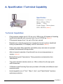
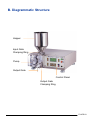
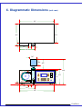
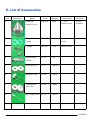
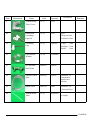
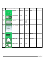
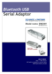
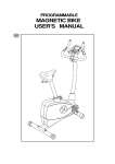
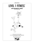
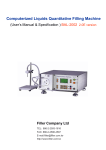
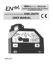
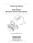
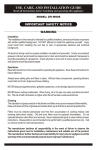
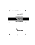
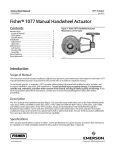
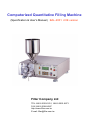
Computerized Quantitative Filling Machine
(Specification & User’s Manual) BAL-2001 2.0E version
Filler Company Ltd
TEL: 886-2-2593-1616, 886-2-2591-6873
FAX: 886-2-2586-4587
http://www.filler.com.tw
E-mail: [email protected]
Content
A. Specification / Technical Capability
….…….……….
01
…………….……………
03
……………….………..
04
………………………….……..
05
B. Diagrammatic Structure
C. Diagrammatic Dimensions
D. List of Accessories
E. Warnings & Emergency Measures
…………….…..
08
………………………...
09
….………………………..
10
….…………………….
14
………….…………………..
17
J. Setting Up Filling Parameters & Function Mode ………
18
K. Important Tips for Effective Operation
21
F. Control Panel Introduction
G. Assembling Procedure
H. Disassembling Procedures
I. Operation Procedures
L. Using Intake Hose & Filter Set
M. Using Hand-held Set
……………….
…….…
23
……………
24
....….…………………
25
(Intake alternative)
(Output alternative)
N. Warranty & Proof of Purchase
O. Maintenance & Replacement Record Sheet
...…….…
27
FILLER 00
A. Specification / Technical Capability
Specification:
Dimensions:L x W x H:
48cm x 42cm x 25cm
Weight : 29 kg
Power Supply:Mono-phase
220V, 50/60Hz (*Note 1)
Technical Capabilities:
•
•
Filling capacity ranges from 0.125 ml up to 1000 ml per fill Capable of Handling
liquid/viscid materials with viscosity from 0 up to 100,000 cp. (Note 2)
Filling speed ranges from 3 ml up to 60 ml per second.
•
Materials are metered precisely by computerized control system, digitalized
setting of parameters, LCD display, and AC servomotor. (Note 3)
•
Patent non-piston filling operation (peristalsis pump) ensures zero percent
material transformation during process.
•
Able to transmit materials of liquid/viscid form at room temperatures or
warmer. (Note 4)
•
Medical/food grade Transmission Tube guarantees contamination-free
transmission.
•
Top grade industrial stainless steel (no. 306) is utilized for all major parts
and accessories.
•
3 Different sized Extruding Pipes are provided to fill bottles with different sized
openings easily.
•
Interchangeable use of “Test”, “Manu”, Auto”, and “Pedal Switch” functions
optimizes production.
FILLER 01
•
“10 minutes” cleaning procedure totally eliminates excess labor.
•
“Motor” switch, in addition to “Power” switch, guards against
unexpected incidents during operation.
•
An ideal liquid/viscid material-filling machine to be used for industries
such as foods, cosmetics, and pharmacy.
Note 1: Single phase 220V is required to operate this machine. Operating on low volt wire may
cause great danger such as short circuit or fire.
Note 2: Range of viscosity is to be used as a general reference only. Actual filling feasibility is
subject to all other factors not mentioned herein, e.g. evaporation speed, material weight,
physical form change due to temperature change,etc.
Note 3: Error range is 0.2% ~0.3%, while average industrial error at 1%.
Note 4: This machine can handle liquid/viscid material kept in the Hopper with temperature up to
90-degree Centigrade. The Transmission Fixture and Transmission Pipes have no problem to
transmit the warm/hot material intended. However, please note that there will be a temperature
change (number of degrees changed are subject to factors such as surrounding environment,
nature of the material itself, etc.) the moment material is extruded from the Extrusion Pipe. There
are some material types that their physical form is quickly changed within an extremely short
period of time frame due to temperature change (for example, some wax based cosmetics
products); this machine is definitely not made to handle them. Please contact us for custom
made order that can handle such – for instance, a heating jacket, and an automatic stirring stick,
etc. will be added into the features.
FILLER 02
B. Diagrammatic Structure
Hopper
Input Gate
Clamping Ring
Pump
Output Gate
Control Panel
Output Gate
Clamping Ring
FILLER 03
C. Diagrammatic Dimensions (unit: mm)
425
465
425
38
100
50
185
307
260
425
640
Computerized Quantitative Filling Machine
BAL-2001
POWER
215
MOTOR
195
F1
START
F2
STOP
30
100
50
185
425
FILLER 04
D. List of Accessories
Item
Illustration
Name
Code
Quantity
Description
Remarks
20-Liter
(Optional)
1
Hopper &
Hopper Cover
FM-H15
1 unit
15-Liter
Stainless-Steel
2
Clipped Rubber
Gasket
FM-L03
5 pieces
Inner Diameter:
1 Inch
3
Clamper
FM-L01
3 sets
Stainless-Steel
4
Transmission
Fixture
CF-01
1 set
5
Drop-out Pad
CF-47
2 pieces
6
Drop-out Tool
CF-48
1 piece
7
Transmission
Tube Nut
CF-49
2 units
8
Nut Fixing Tool
CF-50
1 piece
FILLER 05
Item
Illustration
Name
Code
Quantity
Description
9
Transmission
Tube Cover
CF-57
1 set
10
Hand-held
Extruding
Pipe Set
CF-52
1 set
Pipe,
Drop-out Pads,
Extension Tube
11
Extruding
Pipe
CF-51
3 pieces
Large: 7 mm
Medium: 5 mm
Small: 3 mm
12
Pipe Buckle
Washer
CF-26
1 Washer
13
90˚ Stainless
Steel Joint
FM-L02
1 piece
14
Stainless Steel
Joint
FM-L06
1 piece
Diameter 3/4”
Attached on
Intake-hose
already
15
Intake Hose
FM-T04
5feet
Diameter 3/4〞
(Vacuum Pipe)
16
Transmission
Tube
CF-53
30 pieces
27 cm
in length
Remarks
FILLER 06
Item
Illustration
Name
Code
Quantity
Description
Remarks
6mm
17
Hexagon
Wrench
FM-A01
1 piece
18
Pedal Switch
CF-38
1 set
19
Tool Box
FM-X01
1 box
with
cover
20
User’s Manual
FM-B2001
1 copy
21
Cleaning tools
FM-C01
1 set
(3 sizes)
Brushes
22
Filter Cloth
CF-46
1 set
30 x 60 cm
23
Filter Fixture
CF-45
1 set
FILLER 07
E. Warnings & Emergency Measures
Warnings –
1. Use “Mono-phase 220V” (+/-10% is acceptable) power supply ONLY since this
machine is equipped with industrial serve-motor and driver.
2. Must carefully read through instructions given in this User’s Manual before
operating this machine.
3. Connect the ground wire along with the plug properly before use. Never attempt
to dismantle the ground wire.
4. Avoid any careless operation at all time.
5. Turn off the Power while it’s not in use for a long time.
6. Disassembling the main body of machine is strictly prohibited. Action of such
automatically results in warranty to be totally voided.
Emergency Measures –
Immediately unplug the power in case of any abnormal output continually performed
by the machine. Contact us right away for further assistance.
FILLER 08
F. Control Panel Introduction
7
1
Filler Co., Ltd.
BAL-2001
Computerized Quantitative Filling Machine
POWER
2
6
MOTOR
F1
START
F2
STOP
13 14
8
9
10
11
12
4
3
5
1. LCD shows filling parameters and function mode to be set
2. Power On/Off
3. Motor On/Off
4. Start / Stop to fill (“Stop” also for canceling the “Test” no. )
5. Connect “Pedal Switch”
6. Up / Down keys for the filling parameters on the Left in LCD
7. Up / Down keys for the function mode on the Right in LCD
8. Thousands digit --- Increase/Decrease the number
9. Hundreds digit ------Increase/Decrease the number
10. Tens digit ----------- Increase/Decrease the number
11. Ones digit ---------- Increase/Decrease the number
12. Lights indicating Start/Stop of filling action
13. F1 – Record the test no. & change to Manual mode
14. F2 – Reset “Sum” in LCD
FILLER 09
G. Assembling Procedure
Please note : Assemble the machine only in “power off” condition
1. Place the Drop-out Pads and Transmission Tube Nuts onto Transmission
Fixture, then insert one Transmission Tube. Turn Transmission Tube Nuts
on both sides tightly until the Transmission Tube perfectly adheres to
Transmission Fixture.
Nut Fixing Tool
2. Set Transmission Fixture onto the machine with bolt in its proper position
according to the angle shown below. Lock it securely by using the 8mm
Screw (1), (2) provided.
(1)
(2)
FILLER 10
3. Connect Transmission Tube Cover as shown below, then rotate it
counterclockwise and insert its bolt accordingly.
Fasten the “Ring” underneath (3), then tighten screws (1) and (2).
(1)
(2)
(3)
4. Alternatives on the Input Gate - to suck material from:
(a) the Hopper, (b) the Intake Hose.
(a) The Hopper: Place Clipped Rubber Gasket (4) and Hopper on
Input Gates shown below (5), then lock them together with the
Clamper provided (6).
Using the Hopper Cover will definitely help keep the material clean.
(6)
(4)
(5)
FILLER 11
(b) Intake Hose: (Please also refer to instructions on page 21)
Connect the first Clipped Rubber Gasket (1) and the 90 degree Stainless Steel
Joint (2) with Input Gate, and lock them by using a Clamper (3). Add the second
Clipped Rubber Gasket (4) and the Intake Hose (5) onto the open side of the
Stainless Steel Joint, and fasten them with another Clamper (6).
Please refer to below pictures for how to properly set up the filter cloth.
(6) (2)
(1)
(5)
(4)
(3)
5. Alternatives on the Output Gate – to extrude material through (a) Extruding Pipes
(3 different sizes provided), or (b) Hand-held Extruding Pipe Set (filling via (b) is
recommended to fill liquid type material only as the actual output volume may be
intervened by the weight and viscosity of viscid type material).
(a) Extruding Pipes:
Put a Clipped Rubber Gasket between the Extruding Pipe (3 different sizes
provided) and the Output Gate. Use a Clamper to fasten them.
FILLER 12
(b) Hand-Held Extruding Pipes Set: (Please also refer to instruction on page
page 21 item #4 and page 24)
Please follow the steps shown on below diagram. Connect the Extruding Pipe (1),
Pipe Buckle Washer (2), Drop-out Pad (3), Hand-Held Extension Tube(4),
the other Drop-out Pad (5), Hand-held Extruding Pipe (6) accordingly,
and use a Clamper (7) to fasten the Extruding Pipe (1) and Output Gate.
(7)
(1)
(2) (3)
(4)
(5)
(6)
6. Review once more to ensure aforementioned assembling procedures are
followed properly.
Assembling procedures completed.
FILLER 13
H. Disassembling Procedures
Note: Disassembling procedure can only be performed while machine is shut off
1. Make sure there’s no material left in the Hopper or the Intake Hose.
Loosen the Clamper locking the Input Gate with Hopper or the
Stainless Steel Joint connected with Intake Pipe.
Clamper
Input Gate
2. Loosen the Clamper to separate the Output Gate and Extruding Pipe.
FILLER 14
3. Loosen the screws (1), (2) on the Transmission Tube Cover, the binding Ring (3),
and rotate the Transmission Tube Cover for ~90o clockwise to allow removing it
from machine.
(1)
(2)
(3)
4. Loosen the screws (4), (5) on the Transmission Fixture and remove it from machine.
(4)
(5)
FILLER 15
5. Loosen the Transmission Tube Nuts (1), (2) with Nut Fixing Tool (3).
Use the Drop Out Tool (4) to push it out (disconnect) from the Transmission Fixture.
(1)
(3)
(4)
(2)
Disassembling procedures completed.
FILLER 16
I. Operation Procedures
*Remember to always turn the Motor “off” when you’re away from the machine
1. Double check if all parts are properly assembled according to
Assembling Procedures.
2. Carefully pour intended material into the Hopper. If extension Intake
Hose is used, make sure the material is positioned in a level that
allows smooth suction/flow performed by machine’s Serve Motor. (Note 1)
3. Turn the Power On.
4. Adjust Filling Parameters & Function Mode. (Please see “J. Setting Up
Filling Parameters” on page 18, 19, 20.)
5. Turn the Motor on.
6. Properly place vessel under Extruding Pipe.
7. Press the “Start” button and intended material will be metered and filled
into the vessel.
8. Repeat step 6 & 7 for next filling.
Note:
1. Under normal condition according to general industrial practice, machine’s
Serve Motor is powerful enough to suck liquid and viscid materials from
containers other than attached Hopper. However, factors such as weight,
texture, and evaporation speed of the materials all play important roles deciding
whether the suction can be performed by this machine. Please send us sample
material(s) for free testing. Before your purchase decision is made, we’ll provide
confirmation that this machine is able to perform expected filling functions. Such
confirmation is necessary to obtain the Warranty set forth in this User’s Manual.
FILLER 17
J. Setting Up Filling Parameters & Function Mode in LCD
Please note:
a) All the figures set for the parameters LCD are to be used as “indicators” to
achieve desired precision.
b) With built-in time-delayed protection, machine will “restart” 7 seconds after
being shut down.
c) We purposely design this machine to begin operating only after the action
initiating button being “released” since all buttons on this Machine are “action
sensitive”. In another words, you will see (I) any “number changes” made on
the parameters or “cursor’s movement” between functional choices (e.g. Test,
Auto, Manual, & Sum) in LCD; (ii) actions initiated by the “Start” button, will
take place only after the change-initiating or action-initiating button being
released. All functional buttons, except the “Stop”, as well as the Pedal Switch
are subject to this design in order to achieve maximum precision.
1. Speed (00 ~19): “00” gives minimum speed at 3ml per second, and “19” gets
maximum 60 ml per second. In between, the output quantity increases 3ml while
the number goes up by “1”. When speed is high, the extrusion of material may
cause splash, heavy drops, bubbles, etc. according to its nature. Before the formal
filling begins, please try out various speed levels until best outcome is achieved.
2. Interval (0~9): This represents a short period of time given to allow flexible
movement (such as changing or replacing vessels) during continual
(Auto mode only) operation. Number “0” gives minimum interval at 0.5 second.
As the number goes up by 1, interval increases by 0.5 second.
This machine gives maximum interval 4.5 seconds between fillings.
3. Suck Back (00~99): This design aims at preventing unnecessary dripping to ensure
precise volume filled, and helping keep the workplace clean.
“00” is good for “liquid” type material as such is light enough not to let gravity pull
any drops down. The number should go up while the weight and viscosity of material
increase. Before actual operation starts, please try setting the number from lower
level then increase until there’s no dripping after each fill.
FILLER 18
4. Volume (filling quantity)(0000 ~ 9999):
(1) Move the function mode to “Test”. After finishing the parameter
record, start the quantitative filling job. Please refer the later
paragraph (6. Test).
(2) Machine’s built-in computer program takes “8” as the factor to convert the
desired actual output volume (in ml) into a figure capable of telling machine
to act based on minute difference. Actual output can be achieved by using
below equation:
“Actual Output Volume (in ml) x 8 = The Number to be Set Here”
For example, in order to get 5ml cream extruded from the machine, use the
equation 5 x 8 = 40, you may set the Number at 0040 (5 x 8 = 40) or do some
adjustment by your need. The output quantity increases 0.1~0.12ml while the
number goes up by “1”, it depends on the material quality.
5. Sum: This number gives an idea of how many times the extrusion of material have
been performed by the machine so far according to your set up. To reset the number
back to zero, press F2 key on Control Panel.
We’ve added a small safety feature here: The machine will not operate while the
cursor (on the right hand side of LCD) is pointing the “Sum”.
6. Test: Operating under this function mode provides a free zone to locate the best
Volume setting for intended jars/bottles. Move the cursor pointing at “Test” in LCD,
set approximate levels for “Speed” and “Suck Back”, leave Volume at “0000”
(Note: Under “Manu” & “Auto” mode, machine will not operate when Volume is left at
“0000”), you can start extruding material into a jar/bottle (let’s say it’s a 100ml jar)
by pressing the “Start” button or “Pedal Switch”. When you see the jar/bottle is filled
at “the level” you want, just release the button or Pedal to stop. Take a look at the
Volume parameter in LCD, it must show a number (e.g. 0765) that represents
“the level” you’ve filled the material into the jar/bottle.
Then, press F1 key on the Control Panel to record this number for next filling by
Auto or Manu. and you’ll see the functional cursor is automatically moved to point
at “Manu” mode while the settings (Volume / Speed / Suck Back) under Test mode
stay unchanged (e.g. Volume showing 0765 in this case). At this time, you may
choose to stay at this Manu mode to fill jars/bottles one at a time, or further move
the functional cursor to pointing at “Auto” and start a continual operation.
FILLER 19
7. Manu: Selecting this function mode gives a one-time filling action every time when
you i) press the Start key on the Control Panel or ii) tap the Pedal Switch. Please use
this mode to handle small quantity of filling, or to settle practice before a large number
of automatic fillings (Auto mode) starts. (Note: Under “Manu” mode certain numbers
must be set for “Speed”, “Suck Back”, & “Volume” to make machine operate.)
8. Auto: Selecting this function will enable machine to automatically repeat filling
action according to previously set parameters of Speed, Interval, Volume, and Suck
Back. Press Start (Stop) key on the Control Panel to begin (end) the automatic
operation.
After turned off and restart, the filling machine will memorize all parameters (except the
MODE, which will be in Manual) in last operation. You can use these setting to
continue filling task or reset any parameters.
Since the machine memorizes only one latest setting, please still keep necessary
records in your log or note book.
FILLER 20
K. Important Tips for Effective Operation
1.
Carefully clean all parts that have direct contact with transmitted material, such as
the Hopper & its cover, Clipped Rubber Gasket, Transmission Fixture,
Transmission Tube, Extruding Pipe, Hand-held Extension Tube & Hand-held
Extruding Pipe, Pipe Buckle Washer, Stainless Steel Joint, Intake Hose (while
sucking material from the container other than the Hopper), and Filter Fixture.
According to our records, an experienced staff may need only 10 ~ 15
minutes effort to clean all above-mentioned items. We’ve prepared three
special-sized and easy-to-handle brushes in the package for you. Suggest using
the largest brush for the Transmission Fixture, the medium for the Transmission
Tube, and the small for the Extruding Pipe.
2.
Always thoroughly clean the Transmission Tube right after it’s been used for a set
cycle of operation and machine is shut down to rest. Let it be completely dry
before using it again. Avoid letting it sit under direct sunlight as the sunray may
weaken its strength. Under proper care, a Transmission Tube can last up to 20 ~
30 days based on a continual 8-hours usage per day. We’ve included plenty in
the package for you to use interchangeably.
3.
Above-mentioned parts that need to be cleaned after use are generally
dishwasher safe. Hot water with temperature up to 100-degree Centigrade is
generally ok to wash them.
4.
The Hand-held Extruding Pipe set is designed to help ease the workload of filling
very small bottles or bottles with small openings; especially for the liquid type
material. For example, there are 5 rows of 3ml-bottles with 10 bottles on each
row that are firmly positioned on a working table and ready to be filled with skin
toner. We can use the Hand-held Extruding Pipe set to manually fill them within a
surprisingly short period of time. However, if the material intended to fill is
thicker and heavier, adjustments of the settings on parameters in LCD are
necessary to achieve desired result. Besides, whether or not the thin and
long Hand-held Extension Tube can be thoroughly and easily cleaned after
use is another question to be answered.
FILLER 21
5. This machine can handle material kept in the Hopper with temperature up to 90degree Centigrade. The Transmission Fixture and Transmission Pipes have no
problem to transmit the warm/hot material intended. However, please be aware
that there will be a change (the number of degrees are subject to
surrounding environment and actual condition) in temperature the moment
the material is extruded from the Extruding Pipe. There are some material
types that their physical form will be changed within a very short period of
time due to temperature change (for example, some wax based cosmetics
products); this machine is definitely NOT made to handle them. Please
contact us for custom made order that can handle such –for instance, a
heating jacket, and an automatic stirring stick, etc. will be added into the
features.
6. Always try out setting different levels for the parameters and under “Test” mode in
LCD a few times before formal and continual operation takes place.
7. Remember to record the numbers you’ve set for each parameter based on
different materials, or for different size of jars. Keep all records in one place (e.g.
one notebook) for future reference.
FILLER 22
L. Using Intake Hose & Filter Set
Note: The filter cloth is meant to filter LIQUID type material ONLY (not lotion or cream type viscid
material)
1) Please refer to page 12 (b) for proper connection of Intake Hose.
2) Using the Filter Fixture & Filter Cloth:
Cut a small piece of Filter Cloth and put in between the Filter Fixture as shown
below. Put them together and connect them with the Intake Hose.
Filter cloth is applied on the
other end of the intake Hose
Use filter fixture
filter
feet out
Note: We added three tiny feet on the bottom of the Filter Fixture. With the feet facing out, this
feature helps ensure a clean and smooth suction when using Intake Hose to suck liquid material
from a container other than the Hopper.
FILLER 23
M. Using Hand-held Extruding Pipe set
Please also refer to page 13 (b)
1) Please use the large size Extruding Pipe and turn the nozzle to be pointing upward
2) Insert one Drop-out Pad to the Extruding Pipe, connect the long Hand-held
Extension Tube, add the other Drop-out Pad, and connect Hand-held Extruding
Pipe (Accessories List No. 10 on Page 6) as shown below. The “Drop-out Pads”
are very useful when you need to remove these parts from each other after the
operation has been done.
FILLER 24
N. Two (2) Years Limited Warranty - Worldwide
Filler Co. warrants their standard products against defects in their operation and nonconsumable materials under normal use for a period of Two (2) YEARS from the date of
purchase by the original purchaser (“Warranty Period”). When a non-consumable hardware
defect arises within the Warranty Period, a claim written in detail is to be received by Filler
Co. within 30 days of the date the defect was discovered. At its option, Filler Co. will either
(1) repair the hardware defect at no charge, using new or refurbished replacement parts, or
(2) exchange the product with a product that is new or which has been manufactured from
new or serviceable used parts and is at least functionally equivalent to the original product.
This Limited Warranty does not apply to the damage caused by failure to either (1) follow
instruction relating to the product’s use, or (2) handle, fill, transmit, wash, clamp, and/or
manufacture the materials that are feasible and agreed upon through product testing
beforehand and under general industrial acceptance.
Except as provided in this Warranty and to the extent permitted by law, Filler Co. shall not be
liable for any direct, special, incidental, or consequential damages of any kind, including, but
not limited to any expenses for removal or reinstallation resulting from a defect; loss of use;
loss of revenue; loss of actual or anticipated profits (including loss of profits on contracts);
loss of the use of money; loss of anticipated savings; loss of business; loss of opportunity;
loss of goodwill; loss of reputation; loss of, damage to or corruption of material; or any
indirect of consequential loss or damage howsoever caused including the replacement of
equipment and property, any costs of recovering, programming, or reproducing any material
stored, filled, transmitted, handled, washed, clamped or used with Filler Co.’s products.
In practical terms:
1) We warrant this machine with quality of performing steady operation in normal use
(based on existing industrial standard) according to its design, for two years counting from
the date of purchase. .
2) Parts that are considered consumables (such as Filling Pipe, Hand-held extension Pipe,
Intake Pipe, etc.) are not covered under this warranty.
3) Parts & labor will be charged additional if the breakdown of machine is due to following:
•
•
•
•
•
Unauthorized disassembling of the machine.
Unauthorized operation based on instructions NOT included in User’s Manual.
Inappropriate power supply voltage applied.
Damage from rats, insects, poor working condition, and natural disasters.
Accident caused by failure in following instructions on assembling, disassembling, and
cleaning procedures. (for example, sinking/soaking machine into water)
FILLER 25
* Proof of Purchase *
Owner’s Name
Address
Article
Purchase Date
Manufacturer
Model
Filler Co., Ltd.
Company Seal
BAL-2001
TEL
+886-2-2593-1616
FAX
+886-2-25864587
1. We warrant the quality of this machine, in normal use, for two years from the
date of purchase. Consumables are not under warranty.
2. Under warranty, partial material costs and service charges are
necessary to repair the breakdown owing to :
a. Irregular use against the User’s Manual
b. Unauthorized disassembling
c. Inappropriate power supply voltage applied
d. Private modification
e. Disasters, rats and insects
f. Personal factors (sinking / soaking into water) to cause severe damage
FILLER 26
O. Maintenance Record Sheet
Date
Maintenance Item
Signature
FILLER 27