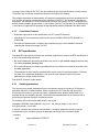
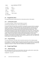
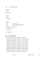
1
CoreConnect Test Generator (CTG) User’s Manual Version 1.6 SA-14-2544-04 Preliminary Edition (March 2001) This edition of CoreConnect Test Generator (CTG) User’s Manual applies to the IBM Daytona verification tool, until otherwise indicated in new versions or application notes. The following paragraph does not apply to the United Kingdom or any country where such provisions are inconsistent with local law: INTERNATIONAL BUSINESS MACHINES CORPORATION PROVIDES THIS MANUAL “AS IS” WITHOUT WARRANTY OF ANY KIND, EITHER EXPRESSED OR IMPLIED, INCLUDING, BUT NOT LIMITED TO, THE IMPLIED WARRANTIES OF MERCHANTABILITY AND FITNESS FOR A PARTICULAR PURPOSE. Some states do not allow disclaimer of express or implied warranties in certain transactions; therefore, this statement may not apply to you. IBM does not warrant that the products in this publication, whether individually or as one or more groups, will meet your requirements or that the publication or the accompanying product descriptions are error-free. This publication could contain technical inaccuracies or typographical errors. Changes are periodically made to the information herein; these changes will be incorporated in new editions of the publication. IBM may make improvements and/or changes in the product(s) and/or program(s) described in this publication at any time. It is possible that this publication may contain references to, or information about, IBM products (machines and programs), programming, or services that are not announced in your country. Such references or information must not be construed to mean that IBM intends to announce such IBM products, programming, or services in your country. Any reference to an IBM licensed program in this publication is not intended to state or imply that you can use only IBM’s licensed program. You can use any functionally equivalent program instead. No part of this publication may be reproduced or distributed in any form or by any means, or stored in a data base or retrieval system, without the written permission of IBM. Requests for copies of this publication and for technical information about IBM products should be made to your IBM Authorized Dealer or your IBM Marketing Representative. Address comments about this publication to: IBM Corporation Department YM5A P.O. Box 12195 Research Triangle Park, NC 27709 IBM may use or distribute whatever information you supply in any way it believes appropriate without incurring any obligation to you. Copyright International Business Machines Corporation 1996, 2000. All rights reserved 4321 Notice to U.S. Government Users – Documentation Related to Restricted Rights – Use, duplication, or disclosure is subject to restrictions set forth in GSA ADP Schedule Contract with IBM Corporation. Patents and Trademarks IBM may have patents or pending patent applications covering the subject matter in this publication. The furnishing of this publication does not give you any license to these patents. You can send license inquiries, in writing, to the IBM Director of Licensing, IBM Corporation, 208 Harbor Drive, Stamford, CT 06904, United States of America. The following terms are trademarks of IBM Corporation: IBM CoreConnect Other terms which are trademarks are the property of their respective owners. Contents Contents. . . . . . . . . . . . . . . . . . . . . . . . . . . . . . . . . . . . . . . . . . . . . . . . . . . . . . . . . . . . . . . v Figures . . . . . . . . . . . . . . . . . . . . . . . . . . . . . . . . . . . . . . . . . . . . . . . . . . . . . . . . . . . . . . . vii Tables. . . . . . . . . . . . . . . . . . . . . . . . . . . . . . . . . . . . . . . . . . . . . . . . . . . . . . . . . . . . . . . . ix About This Book . . . . . . . . . . . . . . . . . . . . . . . . . . . . . . . . . . . . . . . . . . . . . . . . . . . . . . . xi Chapter 1. Overview . . . . . . . . . . . . . . . . . . . . . . . . . . . . . . . . . . . . . . . . . . . . . . . . . . . . . 1 CTG Toolkits . . . . . . . . . . . . . . . . . . . . . . . . . . . . . . . . . . . . . . . . . . . . . . . . . . . . . . . . . . . . . . . . CTG Supertables . . . . . . . . . . . . . . . . . . . . . . . . . . . . . . . . . . . . . . . . . . . . . . . . . . . . . . . . . . . . . Graphical User Interface Configuration Tool . . . . . . . . . . . . . . . . . . . . . . . . . . . . . . . . . . . . . . . . Terms and Definitions . . . . . . . . . . . . . . . . . . . . . . . . . . . . . . . . . . . . . . . . . . . . . . . . . . . . . . . . . Bus Compliance Process Flow . . . . . . . . . . . . . . . . . . . . . . . . . . . . . . . . . . . . . . . . . . . . . . . . . . 1 1 1 1 2 Chapter 2. Graphical User Interface . . . . . . . . . . . . . . . . . . . . . . . . . . . . . . . . . . . . . . . . 3 GUI Overview . . . . . . . . . . . . . . . . . . . . . . . . . . . . . . . . . . . . . . . . . . . . . . . . . . . . . . . . . . . . . . . 3 GUI Implementation . . . . . . . . . . . . . . . . . . . . . . . . . . . . . . . . . . . . . . . . . . . . . . . . . . . . . . . . 5 Graphical User Interface Environment . . . . . . . . . . . . . . . . . . . . . . . . . . . . . . . . . . . . . . . . . . . . 5 Configuration Files . . . . . . . . . . . . . . . . . . . . . . . . . . . . . . . . . . . . . . . . . . . . . . . . . . . . . . . . . . 5 Supertable Files . . . . . . . . . . . . . . . . . . . . . . . . . . . . . . . . . . . . . . . . . . . . . . . . . . . . . . . . . . . . 6 Tcl/Tk Files . . . . . . . . . . . . . . . . . . . . . . . . . . . . . . . . . . . . . . . . . . . . . . . . . . . . . . . . . . . . . . . 6 Choosing GUI Text Color . . . . . . . . . . . . . . . . . . . . . . . . . . . . . . . . . . . . . . . . . . . . . . . . . . . . 6 The GUI at work . . . . . . . . . . . . . . . . . . . . . . . . . . . . . . . . . . . . . . . . . . . . . . . . . . . . . . . . . . . 7 Using the Graphical User Interface . . . . . . . . . . . . . . . . . . . . . . . . . . . . . . . . . . . . . . . . . . . . . . . 7 Using Tcl/Tk with Different Shells . . . . . . . . . . . . . . . . . . . . . . . . . . . . . . . . . . . . . . . . . . . . . . 7 Running the GUI . . . . . . . . . . . . . . . . . . . . . . . . . . . . . . . . . . . . . . . . . . . . . . . . . . . . . . . . . . . 8 Getting Around in the Graphical User Interface Window . . . . . . . . . . . . . . . . . . . . . . . . . . . . . . . 8 Field Types . . . . . . . . . . . . . . . . . . . . . . . . . . . . . . . . . . . . . . . . . . . . . . . . . . . . . . . . . . . . . . . 8 Entry Fields . . . . . . . . . . . . . . . . . . . . . . . . . . . . . . . . . . . . . . . . . . . . . . . . . . . . . . . . . . . . 8 Button Controlled Fields . . . . . . . . . . . . . . . . . . . . . . . . . . . . . . . . . . . . . . . . . . . . . . . . . . . 9 Pull-Down Menus . . . . . . . . . . . . . . . . . . . . . . . . . . . . . . . . . . . . . . . . . . . . . . . . . . . . . . . . 9 Saving Your Work . . . . . . . . . . . . . . . . . . . . . . . . . . . . . . . . . . . . . . . . . . . . . . . . . . . . . . . . . . 9 Supertable Files . . . . . . . . . . . . . . . . . . . . . . . . . . . . . . . . . . . . . . . . . . . . . . . . . . . . . . . . . . . . . . 9 Supertable Structure . . . . . . . . . . . . . . . . . . . . . . . . . . . . . . . . . . . . . . . . . . . . . . . . . . . . . . . 10 Supertable Naming Convention . . . . . . . . . . . . . . . . . . . . . . . . . . . . . . . . . . . . . . . . . . . . . . . 10 Supertable Example File . . . . . . . . . . . . . . . . . . . . . . . . . . . . . . . . . . . . . . . . . . . . . . . . . . . . 10 Configuration Files . . . . . . . . . . . . . . . . . . . . . . . . . . . . . . . . . . . . . . . . . . . . . . . . . . . . . . . . . . . 13 The Structure of the GUI Configuration File . . . . . . . . . . . . . . . . . . . . . . . . . . . . . . . . . . . . . 13 Updating the Configuration File . . . . . . . . . . . . . . . . . . . . . . . . . . . . . . . . . . . . . . . . . . . . . . . 14 Obtaining Tcl/Tk . . . . . . . . . . . . . . . . . . . . . . . . . . . . . . . . . . . . . . . . . . . . . . . . . . . . . . . . . . . . 14 Chapter 3. Bus Functional Generator . . . . . . . . . . . . . . . . . . . . . . . . . . . . . . . . . . . . . 15 Advantages of Use . . . . . . . . . . . . . . . . . . . . . . . . . . . . . . . . . . . . . . . . . . . . . . . . . . . . . . . . . . 15 BFG Features . . . . . . . . . . . . . . . . . . . . . . . . . . . . . . . . . . . . . . . . . . . . . . . . . . . . . . . . . . . . . . 15 Version 1.6 Contents v System Requirements . . . . . . . . . . . . . . . . . . . . . . . . . . . . . . . . . . . . . . . . . . . . . . . . . . . . . . . . BFG Syntax . . . . . . . . . . . . . . . . . . . . . . . . . . . . . . . . . . . . . . . . . . . . . . . . . . . . . . . . . . . . . . . . Program Execution . . . . . . . . . . . . . . . . . . . . . . . . . . . . . . . . . . . . . . . . . . . . . . . . . . . . . . . . . . Invoking the program . . . . . . . . . . . . . . . . . . . . . . . . . . . . . . . . . . . . . . . . . . . . . . . . . . . . . . . Program Display . . . . . . . . . . . . . . . . . . . . . . . . . . . . . . . . . . . . . . . . . . . . . . . . . . . . . . . . . . Sample Input/Output . . . . . . . . . . . . . . . . . . . . . . . . . . . . . . . . . . . . . . . . . . . . . . . . . . . . . . . . . Example input file to BFG . . . . . . . . . . . . . . . . . . . . . . . . . . . . . . . . . . . . . . . . . . . . . . . . . . . Display From the Input File . . . . . . . . . . . . . . . . . . . . . . . . . . . . . . . . . . . . . . . . . . . . . . . . . . Output produced from Input file . . . . . . . . . . . . . . . . . . . . . . . . . . . . . . . . . . . . . . . . . . . . . . . 15 16 20 20 22 23 23 24 25 Chapter 4. Correlation Program . . . . . . . . . . . . . . . . . . . . . . . . . . . . . . . . . . . . . . . . . . 26 Overview . . . . . . . . . . . . . . . . . . . . . . . . . . . . . . . . . . . . . . . . . . . . . . . . . . . . . . . . . . . . . . . . . . Advantages of Use . . . . . . . . . . . . . . . . . . . . . . . . . . . . . . . . . . . . . . . . . . . . . . . . . . . . . . . . Correlation Features . . . . . . . . . . . . . . . . . . . . . . . . . . . . . . . . . . . . . . . . . . . . . . . . . . . . . . . DUT specification . . . . . . . . . . . . . . . . . . . . . . . . . . . . . . . . . . . . . . . . . . . . . . . . . . . . . . . . . . . Omitting parameters . . . . . . . . . . . . . . . . . . . . . . . . . . . . . . . . . . . . . . . . . . . . . . . . . . . . . . . Program Execution . . . . . . . . . . . . . . . . . . . . . . . . . . . . . . . . . . . . . . . . . . . . . . . . . . . . . . . . . . Invoking the program . . . . . . . . . . . . . . . . . . . . . . . . . . . . . . . . . . . . . . . . . . . . . . . . . . . . . . . Program Display . . . . . . . . . . . . . . . . . . . . . . . . . . . . . . . . . . . . . . . . . . . . . . . . . . . . . . . . . . Sample Input/Output . . . . . . . . . . . . . . . . . . . . . . . . . . . . . . . . . . . . . . . . . . . . . . . . . . . . . . . . . Sample input bfg . . . . . . . . . . . . . . . . . . . . . . . . . . . . . . . . . . . . . . . . . . . . . . . . . . . . . . . . . . Sample report file . . . . . . . . . . . . . . . . . . . . . . . . . . . . . . . . . . . . . . . . . . . . . . . . . . . . . . . . . Sample output file . . . . . . . . . . . . . . . . . . . . . . . . . . . . . . . . . . . . . . . . . . . . . . . . . . . . . . . . . 26 26 27 27 27 28 28 28 28 28 29 30 Index . . . . . . . . . . . . . . . . . . . . . . . . . . . . . . . . . . . . . . . . . . . . . . . . . . . . . . . . . . . . . . . . 33 vi CoreConnect Test Generator (CTG) Version 1.6 Figures Figure 1. CoreConnect Test Generator (CTG) Process . . . . . . . . . . . . . . . . . . . . . . . . . . . . . . . . . . 2 Figure 2. GUI Illustration. . . . . . . . . . . . . . . . . . . . . . . . . . . . . . . . . . . . . . . . . . . . . . . . . . . . . . . . . . 4 Figure 3. Visual Interface for Test Generation . . . . . . . . . . . . . . . . . . . . . . . . . . . . . . . . . . . . . . . . . 7 Figure 4. Program Display . . . . . . . . . . . . . . . . . . . . . . . . . . . . . . . . . . . . . . . . . . . . . . . . . . . . . . . 22 Version 1.6 Figures vii viii CoreConnect Test Generator (CTG) Version 1.6 Tables Version 1.6 Tables ix x CoreConnect Test Generator (CTG) Version 1.6 About This Book This book begins with an overview followed by detailed information on the CoreConnect Test Generator (CTG) environment, testbench, bus functional compiler, models and language used in simulation. The CoreConnect Test Generator (CTG) features: • Graphical User Interface - Configures DUTs within Daytona framework for targeted testing. • Bus functional generators (BFG) • Correlation programs • Toolkits - Enhanced CoreConnect tollkit monitors. • Supertables - Transaction-based bus architecture description. Who Should Use This Book This book is for hardware, software, and application developers who need to understand Core+ASIC development and system-on-a-chip (SOC) designs using CoreConnect bus architecture. The audience should understand embedded system design, operating systems, and the principles of computer organization. Since the bus functional model toolkits were developed to comply with the bus architectural specifications, the toolkit users need to have a working level understanding of the architectural specification to be able to develop test cases and simulate using the bus model toolkit. The user should also be familiar with UNIX type operating systems, basic digital logic design and simulation, and the simulator which is used for the verification process. Related Publications The following publications contain related information: Processor Local Bus Architecture Specifications On-Chip Peripheral Bus Architecture Specifications Device Control Register Bus Architecture Specifications Processor Local Bus Toolkit User’s Manual On-Chip Peripheral Bus Toolkit User’s Manual Device Control Register Bus Toolkit User’s Manual Processor Local Bus Arbiter Core User’s Manual On-Chip Peripheral Bus Arbiter Core User’s Manual PLB to OPB Bridge Core User’s Manual OPB to PLB Bridge Core User’s Manual Version 1.6 About This Book xi How This Book is Organized This book is organized as follows: Chapter 1, “Overview” Chapter 2, “Graphical User Interface” Chapter 3, “Bus Functional Generator” Chapter 4, “Correlation Program” To help readers find material in these chapters, the book contains: • “Contents” on page v • “Figures” on page vii • “Tables” on page ix • “Index” on page 33 xii CoreConnect Test Generator (CTG) Version 1.6 Chapter 1. Overview CoreConnect Test Generator (CTG) is a verification tool designed to generate tests that can be used to simulate bus transactions to test compliance for cores that comply with CoreConnect bus architecture. The CoreConnect Test Generator(CTG) consists of graphical user interface(GUI); bus functional generators(BFG); correlation programs; enhanced CoreConnect toolkit monitors; and supertables. 1.1 CTG Toolkits Existing CoreConnect master and slave Bus Functional Models(BFM) are used as transaction generator and response agents using CoreConnect Test Generator(CTG) generated bus functional language(BFL). Monitor enhancements facilitate parameterized bus transaction checking and bus transaction reporting. Automatic data checking built into CoreConnect master and slave models may be used to complement compliance testing. 1.2 CTG Supertables Bus architecture description files used to specify parameters of the following bus transactions: device configuration commands; bus transaction types - read/write; bus transaction parameters - delays, byte enables, etc.; statistical distributions of the above parameters; rules 1.3 Graphical User Interface Configuration Tool A graphical front end written in TCL/Tk. Users are offered a ‘push button’ type interface to specify all relevant bus parameters for master and slave Device Under Test (DUT). CoreConnect BFG rules and command sets for the DUT are automatically generated. Bus architecture details and help facilities are included in the graphical user interface. Transaction depth and ordering is easily edited and embedded in the DUT configuration files. 1.4 Terms and Definitions • Functional Verification Testing the functional behavior of a DUT with respect to its design specifications. • Compliance Test Determines if a core bus interface conforms to the transaction protocol, and attempts to certify that a particular core is capable of operating over the entire range of documented bus transactions and attributes as described in the bus architecture specifications. Version 1.6 Overview 1 1.5 Bus Compliance Process Flow Figure 1 describes bus compliance test generation process. Test 1 Verilog Device Configuration Files Bus Functional Generator BFL Test 2 Bus Functional Compiler MTI VSS BFL Test N Configuration File Generator GUI User Input Figure 1. CoreConnect Test Generator (CTG) Process 2 CoreConnect Test Generator (CTG) Version 1.6 Chapter 2. Graphical User Interface CoreConnect Test Generator (CTG) provides the user with a graphical user interface(GUI) for generating tests. The interface provides the user with a set of selectable fields that correspond to the transaction types and attributes for a particular bus model. The user is able to make selections based on the device that is tested. The selections that are made by the user will then be used to generate input files for the bus functional generator. 2.1 GUI Overview The graphical user interface is used to simplify the generation of configuration tables for a device under test (DUT). It povides an easy to use selection screen for each of the currently used master and slave bus model devices. Version 1.6 Graphical User Interface 3 Figure 2 provides an example of a screen that may be used for a 32-bit PLB master: Figure 2. GUI Illustration As shown in the above figure, the fields that are provided correspond to the possible variable selections available through the PLB bus model. Major features of the CoreConnect Test Generator (CTG) graphical user interface: • Entry and clickable selection of all attributes for a particular bus model. • Reduction of bfl generation time by reduction of the command set. • The ability to save a configuration file for future use • A HELP feature that gives the user immediate access to information from the toolkit workbooks and the architectural specifications. • The ability to create custom rules. 4 CoreConnect Test Generator (CTG) Version 1.6 • The automatic generation of rules based on user selections. This feature will eliminate the generation of unwanted transaction commands in the testcases that are produced. 2.1.1 GUI Implementation The graphical user interface for CoreConnect Test Generator (CTG) has been implemented using Tcl/Tk. The GUI uses the information stored in configuration files to present the user with the correct set of selections. In addition, the GUI also uses information from table files to determine the values for various pre-loaded fields. The user will be provided with a set of template table files and a set of template configuration files. The configuration file stores all necessary selections for a bus model in a structured format that is read in when the GUI is instantiated. The contents of this file change as the user makes selections within the GUI and can be saved to a new file at anytime. The table file is used to determine the values that are applied to several pre-loaded fields within the GUI, an example of this would be the number of test iterations. The table file also contains rules that govern the valid attribute combinations. Changes made by the user to these fields are updated in the table file when the user saves their selections. Figure 3 shows how the GUI functions: 2.2 Graphical User Interface Environment The Graphical User Interface for Test Generation consists of supertables, configuration files, Tcl/Tk files, and a bus functional generator. The configuration files provide the structure, as well as the fields and applicable values for the visual interface. The supertable files provide the information that will be loaded into the visual interface such as the device type. The Tcl/Tk files are the code which use the supertables and configuration files to produce the visual interface. The bus functional generator is called out by the GUI in order to generate user-specified test sets. 2.2.1 Configuration Files The following list of files comprise the available configuration files. • PLB_SUP_MST32_read.tgui / PLB_SUP_MST32_write.tgui • PLB_SUP_MST64_read.tgui / PLB_SUP_MST64_write.tgui • PLB_SUP_MST128_read.tgui / PLB_SUP_MST128_write.tgui These six files represent the selections and values available with a PLB master of the corresponding size. • PLB_SUP_SLV_response.tgui This file represents the selection and values available with a PLB slave of the corresponding size. • OPB_SUP_MST_read.tgui / OPB_SUP_MST_write.tgui These files represent the selections and values available with an OPB master. • OPB_SUP_SLV_response.tgui This file represents the selection and values available with an OPB slave. • DCR_SUP_MST_read.tgui / DCR_SUP_MST_write.tgui These file represents the selections and values available with a DCR master. Version 1.6 Graphical User Interface 5 • DCR_SUP_SLV_response.tgui This file represents the selection and values available with a DCR slave. 2.2.2 Supertable Files The following list of files comprise the available configuration files. • PLB_SUP_MST32.tbfg • PLB_SUP_MST64.tbfg • PLB_SUP_MST128.tbfg These three files represent the preloaded field values associated with a PLB master of the corresponding size. • PLB_SUP_SLV.tbfg This file represents the preloaded field values associated with a PLB slave of the corresponding size. • OPB_SUP_MST.tbfg This file represents the preloaded field values associated with an OPB master. • OPB_SUP_SLV.tbfg This file represents the preloaded field values associated with an OPB slave. • DCR_SUP_MST.tbfg This file represents the preloaded field values associated with a DCR master. • DCR_SUP_SLV.tbfg This file represents the preloaded field values associated with a DCR slave. 2.2.3 Tcl/Tk Files CoreConnect.tcl table_gen.tcl variables.tcl 2.2.4 Choosing GUI Text Color It has been discovered that the same background color will not work in all environments. If the text contents of the GUI window are difficult to see because of the default color, the user can select a different color from within the <variables.tcl> file. Uncommenting the <env_color> of choice will provide a different text color for the GUI. 6 CoreConnect Test Generator (CTG) Version 1.6 2.2.5 The GUI at work Figure 3 shows the interaction of the visual interface for test generation with the bus functional generator and the bus functional compiler(BFC). Graphical User Interface for Test Generation Help File (.hlp, thlp) Table Files (.bfg, tbfg) GUI Configuration File (.gui, tgui) BFL test#1 Bus Functional Generator BFL test#2 Verilog.v or MTI.do or VSS.cmd BFC BFL test#n Figure 3. Visual Interface for Test Generation 2.3 Using the Graphical User Interface The sections that follow describe the process of using and running the graphical user interface. 2.3.1 Using Tcl/Tk with Different Shells It may be necessary to configure the GUI to run with the Bourne shell. This can be done by adding a comment to the GUI in the first line of the table_gen.tcl file. The comment should be: Version 1.6 Graphical User Interface 7 • #!/bin/sh for Bourne shell 2.3.2 Running the GUI Once the availability of Tcl/Tk has been verified and the table_gen.tcl file is ready configure for the correct shell, the GUI is ready to be run. • The GUI is executed with the command CoreConnect.tcl. A large window should appear that contains four pulldown menus. The File menu should be the only menu that is active. • The user can open a configuration file by selecting the File pull-down menu and highlighting one of the following: – New - This will allow the user to open a template file. – Open -This will allow the user to open a previously edited file. – Exit - This will close the GUI. After selecting either New or Open a window will appear that will allow the user to select the file that he/she wishes to work with. After the file is chosen the GUI selection window will appear. The section below describes how to use the selection window. 2.4 Getting Around in the Graphical User Interface Window The sections that follow describe the navigation of the graphical user interface. 2.4.1 Field Types Once the GUI selection window is open, the user will see several fields with several different selection types. The main selection types are: entry, buttons, and menus. 2.4.1.1 Entry Fields Entry fields are areas within the GUI that allow the user to type in a value. In this type of field, the user must place the cursor in the entry field area and type in the desired value. The type of value expected for each entry field is specified next to each field. The possible types are: decimal, binary, hexadecimal, and text. – Text values do not require a special character, and are limited to the upper region of the GUI only. An example of an entry field requiring a text value is the BFG File Name entry field. – Hexadecimal values require that an “x” be placed in front of the value. (x00000000) – Binary values require that a “b” be placed in front of the value. (b0100) – Decimal values do not require a special character. (256) The address field is an example of a hexadecimal entry field. A 64-bit value placed in this field should be specified as follows: x00000000_00000000 to xFFFFFFFF_FFFFFFFF. 8 CoreConnect Test Generator (CTG) Version 1.6 2.4.1.2 Button Controlled Fields Button controlled fields are areas within the GUI that provide a clickable button that corresponds to an associated selection. In this type of field, the user must place the cursor over the button and click with the first mouse button. There are three different types of buttons within the GUI. There are small square and diamond shaped buttons, there are buttons that are labeled with an instruction, and there are buttons that are labeled with a selection. – The small square and diamond shaped buttons are placed next to their associated selection. These buttons are used whenever multiple explicit selections are possible. Square buttons are check buttons and therefore can be active in combination with other square buttons, while diamond buttons are radio buttons and cannot be active in combination with other diamond buttons. – The command buttons are buttons that perform a certain action when they are clicked. An example of this type of button is the Clear Last button under the Command Sequence area in the upper right hand corner of the GUI window. When clicked, this button will clear the last command added to the command sequence. – The selection buttons are used to represent one of two possible values. The value switches whenever the button is clicked, and will alternate between the two possible values. Currently, the only button of this type is used to switch between random and step when using the fields that contain range values. 2.4.1.3 Pull-Down Menus Pull-down menus are located at the top of the GUI. When selected, these menus provide the user with a list of possible actions. 2.4.2 Saving Your Work The user can save their work by selecting the Actions pull-down menu and highlighting either save or save as. – Save is used when the file being worked on has been saved previously(.bfg). – Save as is used when the file being worked on was opened as a template file(.tbfg). 2.5 Supertable Files The visual interface for test generation makes use of the information contained in files that are referred to as supertable files. Because the supertable files are directly used by the bus functional generator they all carry an extension of .tbfg or .bfg. The difference in file extensions represents the difference between a template bfg file and a user-specific bfg file. Each of these file types contain information that pertain to a specific bus functional model device. However, the template file contains the complete set of transaction types, configurable attributes, and attribute values for a particular model device, while the bfg file contains a limited set of values that have been selected by the user. Thus, the template bfg file(.tbfg) is referred to as a supertable. Within the supertable file, information is divided into several different parts, each with its own field name. A description of each of these fields can be found under the bus functional generator section of this document. The visual interface reads in the information contained in each of these fields to complete the information that will be provided to the user in the visual interface window. In addition to Version 1.6 Graphical User Interface 9 reading in the information contained in these files, the visual interface can also update the information with the user selections from the visual interface window and save that information to another file. This new file is important because the bus functional generator will later use the information in this file to generate bfl test sets. The new file will be tagged with the .bfg extension because it has been limited to the user’s selections. 2.5.1 Supertable Structure The supertable file is structured as a set of standardized fields. Each field is made up of a field name that identifies its contents and a corresponding piece or set of data. The contents of each field vary according to the model and device that is being used. A complete explanation of each of the supertable fields can be found under the bus functional generator section of this document. 2.5.2 Supertable Naming Convention The supertable files are named with a standard convention as follows: • [model]_SUP_[device][size of device].tbfg model is PLB, OPB, or DCR device is master(MST) or slave(SLV) size of device is 32, 64, or 128 Example: A 64 bit PLB master supertable file would be name PLB_SUP_MST64.tbfg It is important that the user does not overwrite the supertable files that are provided with the CoreConnect Test Generator (CTG) package. Therefore, the GUI will not allow a user to save a file to the same name as any of the supertable file names. These include: • PLB_SUP_MST32.* • PLB_SUP_MST64.* • PLB_SUP_MST128.* • PLB_SUP_SLV.* • OPB_SUP_MST.* • OPB_SUP_SLV.* • DCR_SUP_MST.* • DCR_SUP_SLV.* It is also recommended that the user does not make any changes to the original supertable files. 2.5.3 Supertable Example File configuration plb_device path /plb_complex/m0/master dut_type plb_slave bfm_type plb_master 10 CoreConnect Test Generator (CTG) Version 1.6 iterations n // user defined iteration value trans_type read write end_trans_type generate list read write // generates a read followed by a write end_generate passthrough pregen all end_passthrough command addr range x00000000_00000000 xFFFFFFFF_FFFFFFFF size enum 0000 0001 0010 0011 1000 1001 1010 1011 \ 1100 1101 be enum 0000 0001 0010 0011 0100 0101 0110 0111 \ 1000 1001 1010 1011 1100 1101 1110 1111 msize req_delay lock unlock_delay type compressed enum 00 range 0 5 enum 0 1 range 0 255 enum 000 //complete toolkit set: 000 001 010 011 100 101 110 111 enum 0 1 guarded enum 0 1 ordered enum 0 1 lockerr //4095 toolkit max enum 0 1 burst_deassert_delay range 0 255 abort_delay priority range 0 255 enum 00 01 10 11 end_command passthrough postgen all Version 1.6 Graphical User Interface 11 end_passthrough //BaseRules //RULES FOR MSIZE and SIZE and BE rule exclude eq msize 00 eq size 0000 ne be 0001 0010 0011 0100 0110 0111 1000 1100 1110 1111 end_rule rule exclude eq msize 00 eq size 1000 1001 1010 ne be 0000 0001 0010 0011 0100 0101 0110 0111 1000 1001 1010 \ 1011 1100 1101 1110 1111 end_rule rule exclude // byte enables for line transfers must be all zeros eq msize 00 eq size 0001 0010 0011 ne be 0000 end_rule //RULES FOR BE and ADDRESS rule exclude eq be 0001 ne addr mask x00000003 value x00000003 end_rule rule exclude 12 CoreConnect Test Generator (CTG) Version 1.6 eq be 0010 0011 ne addr mask x00000003 value x00000002 end_rule rule exclude eq be 0100 0110 0111 ne addr mask x00000003 value x00000001 end_rule rule exclude eq be 1000 1100 1110 1111 ne addr mask x00000003 value x00000000 end_rule //EndBaseRules end_configuration 2.6 Configuration Files GUI configuration files contain the formatting information necessary to produce the graphical user interface(GUI) window for each model device, as well as the rules and commands that are associated with each possible selection from the GUI window. These files are provided with the CoreConnect Test Generator (CTG) package and are updated and saved to new file names when the user saves the selections they make while using the GUI. A standard format has been created for the configuration files. This format is made up of entries and corresponding information for each. 2.6.1 The Structure of the GUI Configuration File The GUI configuration files provide a set of entries that are interpreted by the visual interface and generated in the form of a visual interface selection window. Each entry contains several fields that provide infomation about the entry. The information in the fields include: entry selection type, configuration entry level, entry title, entry label, commands, rules, possible selection values, actual selection values. The entries in the table were formed based on the toolkit specifications. It is not suggested that a user make direct changes to the configuration files(.tgui/.gui). Version 1.6 Graphical User Interface 13 2.6.2 Updating the Configuration File The entries in the configuration file are updated each time a user makes a change within the visual interface window. However, the changes will be lost if the user closes the GUI without saving their work. 2.7 Obtaining Tcl/Tk The Graphical User Interface for test generation is written in Tcl/Tk. Tcl/Tk is a multi-platform, extendable, and free scripting language. When instantiating the GUI you must first ensure that Tcl/Tk interpreter, called wish, is available to you and that you have version 8.0 or higher. This can be done by entering <wish> at the command line and then entering <puts $tk_version> at the % prompt. If 8.0 is not the echoed value then you must first acquire the 8.0 version. Note: On Unix systems wish8.0 may need to be called as such. Therefore typing wish8.0 may be necessary to bring up the 8.0 version. 14 CoreConnect Test Generator (CTG) Version 1.6 Chapter 3. Bus Functional Generator The Bus Functional Generator (BFG) is a program that is used to generate test cases needed for the simulation of a Design Under Test (DUT). In this method an input file is used to specify the conditions for testing. This input file defines the parameters of the bus, the set of possible values for each parameter, the configuration information needed by the DUT, and other conditions for testing. Using this DUT file, the BFG generates all possible tests cases in BFL (Bus Functional Language) format. 3.1 Advantages of Use This automated process of test case generation is extremely beneficial in terms of efficiency. Using a simple input syntax, a user can define the testing conditions for the DUT and generate all tests that would be needed to functionally verify that all components work correctly. With anything more than a trivial design, writing test cases for use in testing can be a long and arduous task. As the number of parameters and parameter values increase, the total set of test cases increases exponentially. Therefore, the use of an automated method substantially reduces the amount of time needed for the production of necessary test cases. As the complexity of functional testing increases, so does the chance for human error. When large testing conditions apply to the testing of a DUT, then it becomes much easier for the testing engineer to forget the inclusion of a specific test case. Therefore, as the complexity of testing conditions grows, this method has a higher likelihood of 100% functional coverage compared to the manual creation of test cases. This program provides an automated method of test case production for use in the simulation of logical components. Using a simple input syntax, information is fed into the program that automatically creates the tests. The syntax of this file is organized into groupings of tags that define the behavior of the program and the method in which tests are generated. The importance of this method is that with a simple and short configuration file, one can generate many tests specifically tailored for the testing of a DUT. Using the rules features and other controlling conditions within the syntax any subset of the total set of possible tests can be produced. (These rule features will be discussed further in the syntax portion of the workbook.) This method allows users to generate a large number of test cases very quickly and easily. 3.2 BFG Features • Definition of rule conditions that may include or exclude a desired set of parameter combinations. • NA (Not Applicable) rule definitions to allow the omission of a specific parameter given a set of conditions. • Easy parameter definitions in a variety of formats. • Ability to specify bfl commands to use during the creation of test cases. These can be a predifined sequence or a random sequence chosen from a predefined list. 3.3 System Requirements The bus functional generator is implemented in Perl, which is an interpreted language distributed under the GNU public license. It is available at no cost and runs on nearly all UNIX or UNIX-like Version 1.6 Bus Functional Generator 15 operating systems. For more information about Perl, visit the Perl home page at http://www.perl.com/perl. 3.4 BFG Syntax The following is a syntax description of a BFG input file. Not all of the following parameter tags are required in a BFG file. • configuration [name] (required) This attribute specifies the bus architecture type. • path [device_path] (required) This attribute specifies the path to the device in the hierarchical model. • bfm_type [name] (required) This attribute specifies the model that is being used to test the DUT (Device Under Test). • iterations [integer or ‘n’] (optional) This attribute specifies the maximum number of iterations the user wishes to output to file. This tag may either be followed by an integer value or by the letter ‘n’. A defined integer value results in no more than that number of iterations to be output to file while the letter ‘n’ results in all possible iterations to be output. If this tag is not included in the bfg file, then the BFG will simply output all possible iterations (according to the rule specifications) in the parameter list. If this tag is omitted or used with the ‘n’ feature, then a long execution time may result for large input files. • file_size [integer] (optional) This attribute specifies the maximum number of iterations to output per file. During execution, an output file is created containing no more than this specified number of iterations. When this maximum number is reached, a new file is created and the output is now changed to this new file. Each file that is created under this method denotes the beginning and ending iterations numbers in the file name. • traverse [1 or 0] (optional) This attribute specifies the behavior of the BFG traversal of the parameter tree. The previously specified iterations tag specifies the maximum number of iterations to be output to a file. The traverse tag, specifies the execution behavior once this number is met. If traverse is set to one or true, then the BFG continues traversal through the parameter list looking for all valid parameter combinations. This stage can be easily seen during execution by the changing of “.” in the status bar to “x”. These x’s denote that the program has finished outputting iterations to file and all future time spent on execution will be used going through the parameter list. If the traversal tag is set to zero or false, then the BFG simply exits once this maximum number has been output. The iterations tag should be included when using this feature. If this tag is included without the iterations attribute, then this tag will simply be ignored. • trans_type (required) [command1] [command2] [command3] .... end_trans_type 16 CoreConnect Test Generator (CTG) Version 1.6 This attribute specifies the bfl commands that will be used during the output of the iterations. These commands may span multiple lines, where the tag end_trans_type denotes the ending of the generation commands. All bfl commands used within the generate tag must first be included here. • generate (required) // specification of a generation list list [command1] [command2] [command3] ... // pick integer=n number of generation commands at random from trans_type list uniform [integer] end_generate This attribute specifies the way in which generation commands are selected during execution. There are two acceptable formats for generation command selection. The first is an enumerated list, where the list keyword is followed by the generation commands the user wishes to generate in each iteration. When the iterations are created by the BFG, these commands will appear in the same order as they are listed. The second format is the uniform keyword followed by an integer specifying the depth of generation commands to be generated. Under this format, the specified number n generation commands are selected at random from the trans_type attribute. The generate tag must be preceded by the trans_type specification. The end_generate tag marks the end of this attribute. • passthrough [pregen or postgen] [all or integer] (optional) [Initialization/Termination command1] [Initialization/Termination command2] .... end_passthrough This attribute specifies the commands the user wishes to include before or after the generation commands. Initialization commands are included before the generation commands with the use of the pregen keyword. Termination commands are included after the generation commands with the use of the postgen keyword. After the pregen/postgen tag are two tags that can specify which iterations to include the initialization and termination commands. If these commands are desired in each iteration, then the tag all is used. Otherwise, an integer value is included that specifies a specific iteration to include the commands. (Note: The iteration count begins at zero and increments by one until n-1 iterations have been output.) The end_passthrough marks the end of this attribute. Multiple passthrough statements may be declared in the bfg file, making it possible to have different combinations of command sequences for different iterations. • command // for an enumerated list [parameter name] [enum] [item1] [item2] [item3] ... // for a range of values, or a uniform random distribution within a range [parameter name] [uniform] [min_value] [max_value] [parameter name] [range] [min_value] [max_value] step* step_value* random_slice(x:y)* // step and step_value are optional and are only used for type range // random_slice is optional and is only used for range parameters Version 1.6 Bus Functional Generator 17 // x and y specify the beginning and ending bit positions to generate random bits ... end_command This attribute specifies the values of the parameters to be used during execution. There are three formats which may be used to describe parameter values. These formats include enum, uniform, and range. For parameters of type enum, the enumeration list simply follows the keyword enum, one list item at a time separated by white space. For parameters of type uniform and range, the beginning and ending values follow the corresponding keyword. During execution, the user may choose a different step value to increment between the minimum and maximum values of the range. During execution the program begins the range parameter at the minimum range value and then increments the current parameter by step_value. The step and step_value tags are optional. If step and step_value are not included within the range definition, then the step_value defaults to 1 and all elements within the range are included. Uniform parameter declarations signify that a random number will be generated somewhere between the minimum and maximum values specified. The user may also generate random subsets for a binary or hexadeimal value with the use of the random_slice field. This optional tag may only be used with range parameters. Within this tag, there are two numbers that specify the beginning and ending bit positions to generate random bits. The first argument specifies the beginning bit position and the second argument specifies the ending bit position. The first argument must be less than the second to correctly specify a random slice field. A specified random slice field functions during execution when a range parameter is updated to the next value through incrementation by the step value. Random bits are then inserted into this value at the appropriate field. This value is then used in combination with any following rules to determine if the value is appropriate for output. This feature preserves the functionality of a range parameter. Parameter values are incremented identically to those without the random_slice tag. The random_slice feature enables a random bit field to be generated for a portion of a binary or hexadecimal value rather than the entire value, as used with the uniform specification. Only parameter values of type enum may span multiple lines in the bfg file. Because some enumeration lists can be very long, the inclusion of all values onto a signal line can cause the input file to become very hard to read. Therefore, enumeration lists may span multiple lines provided that a “\” marks the return to the next line where values are continue to be read. The following is an example of how a parameter could be broken up within the command section of a BFG file. Example: param1 enum 0000 0001 0010 0011 0010 0111 1111 .... (now becomes) param1 enum 0000 \ 0001 \ 0010 \ 0011 \ 0010 \ 0111 \ 18 CoreConnect Test Generator (CTG) Version 1.6 1111 Note: This technique may not be applied to parameter values of type range and uniform. There are three different formats that may be used within range and uniform values: decimal, binary, and hexadecimal. To specify a format, special characters may be included before the min_value and max_value. Hexadecimal is chosen by including an “x” character, binary is chosen by including a “b”, and decimal is default. Examples: x10 //hexadecimal value, equal to 16 decimal b10 //binary value, equal to 1 decimal 10 //decimal value, just plain 10 Note: Format specifications apply only to parameter values of type range and uniform. Parameters declared of type enum are considered by the BFG to be “literals” that are passed directly through to the resulting bfl (permitted the parameter passes all of the rules declarations). There are two other qualifiers that may be applied to parameters within the command section. These qualifiers are applied to parameters as an extra token that appears before the parameter name. The first qualifier denotes that the parameter is optional and may be omitted from the bfl transaction. This qualifier is specified by including a “*” before the parameter name. The second qualifier denotes that the parameter is not to be used for the correlation process and is specified by including a “#” before the parameter name. (See the correlation section for further explanation of behavior.) • rule [include or exclude] [rule_name] (optional) // rule_name is also optional [eq, ne, lt, or gt] [parameter name] [item1] [item2] [item3] [eq, ne, lt, or gt] [parameter name] [mask] [mask_value] [value] [test_value] [eq, ne, lt, or gt] [parameter name] [range] [min value] [max value] ... end_rule This attribute describes rule specifications under the BFG. During execution, rules restrict the total set, defined by the command parameters, to possible subsets for output to BFL. Rules may either exclude or include a combination of parameters based upon the validity of individual tests. These individual tests are included within each rule and may be one of four types: equal (eq), not equal (ne), less then (lt), or greater then (gt). Each rule has some number of individual tests associated with them. If all the individual tests within a rule are true, then the appropriate action is executed (including the parameter combination if the rule is include, and vice versa if the rule is exclude). However, if any of the individual tests are false, then the opposite action is executed (excluding the parameter combination if the rule is include, and vice versa). If more then one rule is used, the values of all the exclude statements are AND’d together, the values of all the include statements are OR’d together, and these two resulting values are AND’d together to achieve a true or false result to include the parameter combination. If no rules are specified, then all parameter combinations are included until the set is exhausted, or until the maximum number of iterations is reached. Individual tests also have three formats: mask, enumerated list, and range. Under mask, the current value of the command parameter is taken and then masked with the mask_value. This resulting value Version 1.6 Bus Functional Generator 19 is then tested upon test_value using the appropriate test condition (eg, ne, lt, or gt). An enumerated list simply grabs the current command parameter and tests it with the items in the list. A range specifies a range of values between a minimum and maximum value. Each individual test returns a true or false condition. Note: The mask_value used in the mask format for individual tests may only be of type binary or hexadecimal. Therefore, mask may not be used with parameters of type enum because they may not be declared as a binary or hexadecimal value. Rule exclude or include serves to filter entire generation lists (or combinations of parameter values) that are either included or excluded from the BFL. Note: It is very important when writing rule declarations to ensure type consistency. The test values declared for a parameter much match the format (decimal, binary, or hexadecimal) of the appropriate parameter in the command section. The BFG will not execute if these formats are not correctly specified. • rule [NA] [parameter_name] (optional) [eq, ne, lt, or gt] [parameter name] [item1] [item2] [item3] [eq, ne, lt, or gt] [parameter name] [mask] [mask_value] [value] [test_value] [eq, ne, lt, or gt] [parameter name] [range] [min value] [max value] ... end_rule This tag allows for the omitting of certain parameters under specific conditions during test case generation. The individual tests under rule NA are identical to those under include/exclude rules. In order for a parameter to be deemed not applicable then all the tests must be true (they are AND’d together). In this situation, the parameter_name is simply left out from the generation list. Unlike rule exclude or include, rule NA serves to filter single parameters located within a generation list. • end_configuration (required) This tag denotes the ending of the bfg file. It must be the last element within the bfg file and is required for normal operation. Note: (Note: Input files to the bfg may be created by hand using this syntax. However, included within the toolkit is a GUI that automatically creates the input bfg.) 3.5 Program Execution This segment describes the process to invoke the BFG, the output of the BFG during execution, and sample input bfg and output bfl files. 3.5.1 Invoking the program The BFG is invoked using the following command: • BFG <input.bfg> 20 CoreConnect Test Generator (CTG) Version 1.6 The input file is specified via command line argument after the BFG command. There are no naming requirements of the input file, although for convention input files usually have an extension of ‘.bfg’. Using this input file, the program executes producing BFL file that is named the input name (stripped of the .bfg extension) with ‘.bfl’ added. Examples: Input File: input.bfg Output File:Input.bfl Input File: input Output File: input.bfl Using the ‘file_size’ tag, the user has the opportunity to restrict the number of tests cases per file producing multiple output files. During execution, each generated test case is assigned a number (starting with 0 to n-1 tests). In this case, the output file produced is named almost the same, except it now contains the test case numbers of the first and last tests that it contains. For example, if an input file produced 389 test cases and the user restricted each file to contain no more then 100 tests, then the following files would be created: Input File: input.bfg Output Files: input_0_99.bfl Input File: Input.bfg Output File: Input_0_99.bfl //contains tests 0-99 Input_100_199.bfl //contains tests 100-199 input_200_299.bfl //contains tests 200-299 input_300_388.bfl //contains tests 300-388 Note: If the message “perl: not found” or other system error is encountered when invoking the BFG, ensure that the path for the Perl executable is correct on the first line of the BFG source as required by the Perl interpreter specification. To locate the Perl executable, try using the UNIX command “which perl.” Version 1.6 Bus Functional Generator 21 3.5.2 Program Display This section describes the information that is output during execution of the BFG. 1. 2. 3. 5. 4. 6. 7. 8. Figure 4. Program Display Figure 4 above shows output of the BFG program given a sample input file. The labels are defined as follows: 1. This is the command used to execute the BFG program. 2. This indicates the number of parameters that are found within the input bfg file. For each parameter, ‘parameter parsing’ is output. For instance, the input file above had 10 parameters within the command syntax tag. 3. This indicates the number of rules found within the bfg file. For each rule, ‘rule parsing’ is output. The input file above had 2 rules (these may be either include, exclude, or NA). 4. This indicates the name of the output file being generated. If the ‘file_size’ tag exists within the bfg file then the name cannot be predetermined, causing this to be omitted. 5. This is the number of test cases that would be created without any rules. This is used as an estimation for the user to judge execution time. 22 CoreConnect Test Generator (CTG) Version 1.6 6. This is the status bar in which ‘.’s are used to indicate the progress in relation to the total projected number of test cases. In the case above, the traverse tag was used to indicate for the program to continue execution even after the maximum number of test cases were output. 7. This indicates the number of test cases that were generated after completion of the program. During execution, "x"s and "."s are used to indicate progress of the program. Periods indicate that the BFG is looking for valid bfl transactions where "x"s indicate that the BFG has already output the maximum number of transcations specified with the iterations tag, but is continuing to look for all valid transactions. In the output above it can be seen that the iterations tag was used to restrict the number of tests to 5 because of the ‘x’s in the status bar. 8. This is the total number of valid tests that were produced during execution. If there is no restriction on the number of test cases, then these two numbers would be the same. However, because the example above restricted the tests to 5, this number indicates that there were still 11 more possible tests in the above set that were not output. 3.6 Sample Input/Output This section describes simple input bfg and output bfl examples. 3.6.1 Example input file to BFG In the following input file, there are three parameters: address, be, and size. Of these parameters, two are of type range given in both hexadecimal and binary formats and the third is an enumeration list with two values. The rule states to only include tests where address is equal to hexadecimal 0001EEE1, size is equal to 1001, and be is either binary 10 or 11. configuration plb_device path /plb_complex/m0/master device_type plb_master trans_type read end_trans_type generate list read end_generate passthrough pregen wait (level=0) Version 1.6 Bus Functional Generator 23 end_passthrough command address range x0001EEE0 x0001EEE8 be range b00 b11 size enum 0001 1001 end_command passthrough postgen send (level=1) end_passthrough rule include eq address x0001EEE1 eq size 1001 eq be b10 b11 end_rule end_configuration 3.6.2 Display From the Input File The following is the output of the BFG as a result of the input file. prompt%>BFG test.bfg transaction types parsing .. generate parsing .. command parsing .. parameter parsing .. parameter parsing .. parameter parsing .. postgen parsing .. rule parsing .. 24 CoreConnect Test Generator (CTG) Version 1.6 generating bfl .. test.bfl total project number :72 [0........|.........|.........|.........|......100%] .......xxxxxxxxxxxxxxxxxxxxxxxxxxxxxxxxxxxxxxxxxxx generated cases: 2 total valid: 2 The display shows that out of 72 possible tests cases that could have been generated from the given parameters and their values, that only 2 were produced in accordance with the specified rules. The maximum number of test cases was not specified because the generated cases and total valid numbers were the same. 3.6.3 Output produced from Input file // Iteration: 0 set_device (path=/plb_complex/m0/master, device_type=plb_master) test (param=1) read(address=0001eee1, be=10, size=1001) send (level=1) // Iteration: 1 wait (level=0) read(address=0001eee1, be=11, size=1001) send (level=1) Version 1.6 Bus Functional Generator 25 Chapter 4. Correlation Program The correlation program is a method that is used to easily gauge the amount of functional coverage that a test (or series of tests) has covered in the total functional verification of a DUT (Design Under Test). This method uses two files to report the coverage. One input file is used to define the parameters of the bus, the possible values for each parameter, and the configurational information needed by the DUT. The second file is produced by HDL monitors that report statements to standard out in hardware simulators that report bus transaction information based upon current parameter values for each transaction that is run accross the bus. Using the information provided by these two files, this method compares the total set of possible parameter combinations with those transactions recorded on the bus. From this, a list is generated that describes the bus transactions that were found to be recorded, transactions that were not recorded but were valid parameter combinations, duplicate transactions, and transactions that were recorded but were not valid according to the specification of the DUT file. 4.1 Overview The correlation program works by calculating all of the possible bus transactions (as specified by the DUT file) and then comparing each one with the bus transactions that were recorded by the monitor of the DUT. If the transaction calculated by the correlator is found within the report file, then that transaction is scored as FOUND by the correlator, where multiple instances of the same transaction are identified as DUPLICATE. If the correlator calculates a transaction that is not found within the report file, then that transaction is marked as MISSING. Otherwise, if transactions are found within the report file that are not calculated by the correlator, then these transactions are marked as UNKNOWN. If the correlator matches up every generated transaction with one in the report file, 100 percent coverage of the DUT has been reached. Otherwise, less coverage has been achieved, and the correlator indicates the transactions that need to be tested to close the gap. The correlation program may also be used with a feedback feature that allows information from previously correlated log files to be used in future correlations. This feedback mechanism allows the user to combine the information of multiple simulations together to produce functional coverage information. This method of feedback allows the user to see the amount of functional coverage that has been increased for each set of tests that are run across the bus. The user can run a specific set of tests and see how much coverage has been obtained. When missing tests are identified, the user may run new tests across the bus, and then feedback the previously created correlation file rather then having to re-simulate prior transactions across the bus for them to appear in the scored coverage. This technique allows the user to simulate relatively small sets of tests and increment total functional coverage of a DUT. This feedback mechanism is important because it allows the user to more easily gauge and achieve 100 percent coverage in the simulation of a DUT while filtering previously exercised transactions. 4.1.1 Advantages of Use This report generation is useful because it allows the user to easily gauge what amount of transaction coverage has been completed during a simulation of a DUT. Using this program, a user may determine what percentage of coverage has been simulated on the bus and what transactions are necessary to achieve 100 percent coverage. This is important because if the user lacks 100 percent 26 CoreConnect Test Generator (CTG) Version 1.6 coverage in the simulation of a DUT, then this method will give that user the ability to easily achieve 100 percent (by running the transactions labeled as missing by this method). This program automates the determination of functional coverage based upon the specifications of a DUT and the information recorded during the simulation of that DUT. This invention is divided into three parts: the generation of a report file through a monitor, the creation of a DUT configuration file, and the actual correlation program itself. In the creation of the DUT configuration file, a simple syntax is used which is organized into groupings of tags that define possible parameters and their values. 4.1.2 Correlation Features • Supertable input syntax for the specification of a DUT. (see BFG features) • Identification of every transaction tested on the bus as: KNOWN, DUPLICATE, MISSING, or UNKNOWN. • Generation of statistics after correlation has completed giving the user valuable information regarding the functional coverage of a DUT. 4.2 DUT specification The same BFG input syntax is used for the correlation program as is used for the BFG specification of a DUT, with the following restrictions: • No random parameter generation: parameters may not be of type uniform, range parameters may not include a random_slice(x:y) field. • BFL command sequence limited to type list and may only contain one command (specified within the trans_type field). • The parameter list order must be consistent with monitor report bfl output parameters. Therefore, the order of the parameter declaration in the input file must match the order in which the parameters are output during simulation. See the BFG Syntax for further details. 4.2.1 Omitting parameters The user may omit certain parameters from the correlation process by including a "#" before the parameter within the command section. When comparing the DUT input file with the log files produced by the monitors, a pound sign before a parameter name allows that parameter to be excluded during the comparing process. Rules that include parameters that are ommitted with a pound sign are ignored during the correlation process. For example, the monitor reports data values in the log file write(addr=10000000, data=00000000, req_size=1, req_delay=0, delay=1, ack_size=4, ack_type=normal ) // time:1860 If the user considers data values as anunnecessary correlation parameter, then they may be ommitted during the correlation process by placing a pound sign in the correlation bfg file. command addr range x00000000 xFFFFFFFF Version 1.6 Correlation Program 27 # data range x00000000 xFFFFFFFF req_size req_delay delay enum 1 range 0 1 range 0 2 ack_size ack_type enum 1 4 enum normal end_command 4.3 Program Execution This segment describes the actions that will occur during the execution of the program. 4.3.1 Invoking the program The correlation program is invoked using the following command: correlate.pl [input_bfg] [report_file] [-o output_file] | [feedback.crl] The input DUT (bfg) and report files are specified via command line arguments after the correlate.pl command. There are no naming requirements of the input files, although for convention DUT files usually have the extension of “.bfg.” The report files are produced by the monitors at simulation. Using these two files, the program executes producing a file identifying all transactions. These transactions are then put into a log file that may be specified by the user with the ‘-o filename’ option. If no output file is specified by the user, then the correlation process is output to the file “correlate.log.” The last option that may be specified includes a feedback file produced by a previous correlation session. (Useful if the user wishes to include previously found transactions into the current correlation, for the purposes of tacking multiple tests together.) The last two options of feedback and the definition of the output file are optional, and need not be included by the user. Also, because they are both optional, they may appear in either order. 4.3.2 Program Display This section describes the information that is output during execution of the correlation program. In this example, the correlation program was invoked using a test DUT and report file. The output file was specified to be “output.file.” After the correlation process was completed, information was printed regarding the number of FOUND, DUPLICATE, MISSING, and UNKNOWN transactions. 4.4 4.4.1 Sample Input/Output Sample input bfg In the following input DUT file, there are 4 parameters: addr, data, req_delay, and ctr_assert_delay. They are all of type enumeration and there are no rules included. configuration dcr_device 28 CoreConnect Test Generator (CTG) Version 1.6 path /dcr_complex/m0/master trans_type read end_trans_type generate list read end_generate command addr enum dd ee ff data enum dddddddd eeeeeeee ffffffff req_delay enum 2 4 6 ctr_assert_delay enum 2 3 end_command end_configuration 4.4.2 Sample report file The following file is produced by a monitor during simulation. read(addr=ee, data=eeeeeeee, req_delay=4, ctr_assert_delay=3) read(addr=ee, data=eeeeeeee, req_delay=4, ctr_assert_delay=3) read(addr=ee, data=eeeeeeee, req_delay=4, ctr_assert_delay=3) write(addr=ee, data=eeeeeeee, req_delay=4, ctr_assert_delay=3) read(addr=ff, data=eeeeeeee, req_delay=2, ctr_assert_delay=3) read(addr=ff, data=eeeeeeee, req_delay=4, ctr_assert_delay=2) read(addr=ff, data=eeeeeeee, req_delay=4, ctr_assert_delay=3) read(addr=ff, data=eeeeeeee, req_delay=6, ctr_assert_delay=2) read(addr=ff, data=eeeeeeee, req_delay=6, ctr_assert_delay=3) read(addr=ff, data=ffffffff, req_delay=2, ctr_assert_delay=2) Version 1.6 Correlation Program 29 read(addr=ff, data=ffffffff, req_delay=2, ctr_assert_delay=3) read(addr=ff, data=ffffffff, req_delay=4, ctr_assert_delay=2) read(addr=ff, data=ffffffff, req_delay=4, ctr_assert_delay=3) read(addr=ff, data=ffffffff, req_delay=6, ctr_assert_delay=2) read(addr=ff, data=ffffffff, req_delay=6, ctr_assert_delay=3) 4.4.3 Sample output file [FOUND][27]:read(addr=ee, data=eeeeeeee, req_delay=4, ctr_assert_delay=3) [DUPLICATE][27]:read(addr=ee, data=eeeeeeee, req_delay=4, ctr_assert_delay=3) [DUPLICATE][27]:read(addr=ee, data=eeeeeeee, req_delay=4, ctr_assert_delay=3) [UNKNOWN]:write(addr=ee, data=eeeeeeee, req_delay=4, ctr_assert_delay=3) [FOUND][43]:read(addr=ff, data=eeeeeeee, req_delay=2, ctr_assert_delay=3) [FOUND][44]:read(addr=ff, data=eeeeeeee, req_delay=4, ctr_assert_delay=2) [FOUND][45]:read(addr=ff, data=eeeeeeee, req_delay=4, ctr_assert_delay=3) [FOUND][46]:read(addr=ff, data=eeeeeeee, req_delay=6, ctr_assert_delay=2) [FOUND][47]:read(addr=ff, data=eeeeeeee, req_delay=6, ctr_assert_delay=3) [FOUND][48]:read(addr=ff, data=ffffffff, req_delay=2, ctr_assert_delay=2) [FOUND][49]:read(addr=ff, data=ffffffff, req_delay=2, ctr_assert_delay=3) [FOUND][50]:read(addr=ff, data=ffffffff, req_delay=4, ctr_assert_delay=2) [FOUND][51]:read(addr=ff, data=ffffffff, req_delay=4, ctr_assert_delay=3) [FOUND][52]:read(addr=ff, data=ffffffff, req_delay=6, ctr_assert_delay=2) [FOUND][53]:read(addr=ff, data=ffffffff, req_delay=6, ctr_assert_delay=3) [MISSING][0]:read(addr=dd, data=dddddddd, req_delay=2, ctr_assert_delay=2) [MISSING][1]:read(addr=dd, data=dddddddd, req_delay=2, ctr_assert_delay=3) [MISSING][2]:read(addr=dd, data=dddddddd, req_delay=4, ctr_assert_delay=2) [MISSING][3]:read(addr=dd, data=dddddddd, req_delay=4, ctr_assert_delay=3) [MISSING][4]:read(addr=dd, data=dddddddd, req_delay=6, ctr_assert_delay=2) [MISSING][5]:read(addr=dd, data=dddddddd, req_delay=6, ctr_assert_delay=3) [MISSING][6]:read(addr=dd, data=eeeeeeee, req_delay=2, ctr_assert_delay=2) [MISSING][7]:read(addr=dd, data=eeeeeeee, req_delay=2, ctr_assert_delay=3) [MISSING][8]:read(addr=dd, data=eeeeeeee, req_delay=4, ctr_assert_delay=2) [MISSING][9]:read(addr=dd, data=eeeeeeee, req_delay=4, ctr_assert_delay=3) 30 CoreConnect Test Generator (CTG) Version 1.6 [MISSING][10]:read(addr=dd, data=eeeeeeee, req_delay=6, ctr_assert_delay=2) [MISSING][11]:read(addr=dd, data=eeeeeeee, req_delay=6, ctr_assert_delay=3) [MISSING][12]:read(addr=dd, data=ffffffff, req_delay=2, ctr_assert_delay=2) [MISSING][13]:read(addr=dd, data=ffffffff, req_delay=2, ctr_assert_delay=3) [MISSING][14]:read(addr=dd, data=ffffffff, req_delay=4, ctr_assert_delay=2) [MISSING][15]:read(addr=dd, data=ffffffff, req_delay=4, ctr_assert_delay=3) [MISSING][16]:read(addr=dd, data=ffffffff, req_delay=6, ctr_assert_delay=2) [MISSING][17]:read(addr=dd, data=ffffffff, req_delay=6, ctr_assert_delay=3) [MISSING][18]:read(addr=ee, data=dddddddd, req_delay=2, ctr_assert_delay=2) [MISSING][19]:read(addr=ee, data=dddddddd, req_delay=2, ctr_assert_delay=3) [MISSING][20]:read(addr=ee, data=dddddddd, req_delay=4, ctr_assert_delay=2) [MISSING][21]:read(addr=ee, data=dddddddd, req_delay=4, ctr_assert_delay=3) [MISSING][22]:read(addr=ee, data=dddddddd, req_delay=6, ctr_assert_delay=2) [MISSING][23]:read(addr=ee, data=dddddddd, req_delay=6, ctr_assert_delay=3) [MISSING][24]:read(addr=ee, data=eeeeeeee, req_delay=2, ctr_assert_delay=2) [MISSING][25]:read(addr=ee, data=eeeeeeee, req_delay=2, ctr_assert_delay=3) [MISSING][26]:read(addr=ee, data=eeeeeeee, req_delay=4, ctr_assert_delay=2) [MISSING][28]:read(addr=ee, data=eeeeeeee, req_delay=6, ctr_assert_delay=2) [MISSING][29]:read(addr=ee, data=eeeeeeee, req_delay=6, ctr_assert_delay=3) [MISSING][30]:read(addr=ee, data=ffffffff, req_delay=2, ctr_assert_delay=2) [MISSING][31]:read(addr=ee, data=ffffffff, req_delay=2, ctr_assert_delay=3) [MISSING][32]:read(addr=ee, data=ffffffff, req_delay=4, ctr_assert_delay=2) [MISSING][33]:read(addr=ee, data=ffffffff, req_delay=4, ctr_assert_delay=3) [MISSING][34]:read(addr=ee, data=ffffffff, req_delay=6, ctr_assert_delay=2) [MISSING][35]:read(addr=ee, data=ffffffff, req_delay=6, ctr_assert_delay=3) [MISSING][36]:read(addr=ff, data=dddddddd, req_delay=2, ctr_assert_delay=2) [MISSING][37]:read(addr=ff, data=dddddddd, req_delay=2, ctr_assert_delay=3) [MISSING][38]:read(addr=ff, data=dddddddd, req_delay=4, ctr_assert_delay=2) [MISSING][39]:read(addr=ff, data=dddddddd, req_delay=4, ctr_assert_delay=3) [MISSING][40]:read(addr=ff, data=dddddddd, req_delay=6, ctr_assert_delay=2) [MISSING][41]:read(addr=ff, data=dddddddd, req_delay=6, ctr_assert_delay=3) [MISSING][42]:read(addr=ff, data=eeeeeeee, req_delay=2, ctr_assert_delay=2) Version 1.6 Correlation Program 31 During correlation, the report file is parsed, and all transactions are identified as FOUND, DUPLICATE, or UNKNOWN. All MISSING transactions were then identified and output. 32 CoreConnect Test Generator (CTG) Version 1.6 Index A about this book xi invoking the correlation program 28 B BFG 15 BFG features 15 BFG program display 22 BFG program execution 20 BFG syntax 16 BFG system requirements 15 BFL 15 bus functional generator 15 bus functional language 15 C CoreConnect text generator 1 correlation features 27 correlation program 26 correlation program display 28 CTG 1 CTG supertables 1 CTG toolkits 1 D design under test 15 display from BFG input file 24 DUT 15 DUT specification 27 O obtaining Tcl/Tk 14 omitting parameters from correlation 27 output from BFG input file 25 R running GUI 8 S sample DUT file 28 sample output file 30 sample report file 29 saving your work 9 structure of GUI configuration file 13 supertable example file 10 supertable files 9 supertable naming convention 10 supertable structure 10 T test generation process 2 U updating GUI configuration file 14 using Tcl/Tk with different shells 7 E example of BFG input file 23 G graphical user interface 3 GUI at work 7 GUI button controlled fields 9 GUI configuration files 5, 13 GUI entry fields 8 GUI environment 5 GUI field types 8 GUI implementation 5 GUI interface 1 GUI pull-down menus 9 GUI supertable files 6 GUI Tcl/Tk files 6 GUI text color 6 I invoking BFG program 20 Version 1.6 Index 33 34 CoreConnect Test Generator (CTG) Version 1.6 © International Business Machines Corporation 1996, 2000 Printed in the United States of America 3/13/01 All Rights Reserved The information contained in this document is subject to change without notice. The products described in this document are NOT intended for use in implantation or other life support applications where malfunction may result in injury or death to persons. The information contained in this document does not affect or change IBM’s product specifications or warranties. Nothing in this document shall operate as an express or implied license or indemnity under the intellectual property rights of IBM or third parties. All information contained in this document was obtained in specific environments, and is presented as illustration. The results obtained in other operating environments may vary. THE INFORMATION CONTAINED IN THIS DOCUMENT IS PROVIDED ON AN “AS IS” BASIS. In no event will IBM be liable for any damages arising directly or indirectly from any use of the information contained in this document. IBM Microelectronics Division 1580 Route 52, Bldg. 504 Hopewell Junction, NY 12533-6531 The IBM home page can be found at http://www.ibm.com The IBM Microelectronics Division home page can be found at http://www.chips.ibm.com Document No. SA-14-2544-04