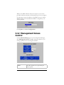
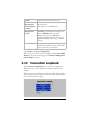
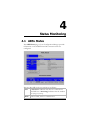
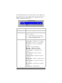
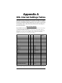
1
ADSL Ethernet Modem U S E R ’ S G U I D E NOTICE This document contains proprietary information protected by copyright, and this Manual and all the accompanying hardware, software, and documentation are copyrighted. No part of this document may be photocopied or reproduced by mechanical, electronic, or other means in any form. The manufacturer does not warrant that the hardware will work properly in all environments and applications, and makes no warranty or representation, either expressed or implied, with respect to the quality, performance, merchantability, or fitness for a particular purpose of the software or documentation. The manufacturer reserves the right to make changes to the hardware, software, and documentation without obligation to notify any person or organization of the revision or change. All brand and product names are the trademarks of their respective owners. © Copyright 2004 All rights reserved. Contents 1. INSTALLATION INSTRUCTIONS ........................................... 1 1.1 IMPORTANT! BEFORE YOU BEGIN ..................................... 1 1.2 PACKAGE CONTENTS ...................................................... 1 1.3 QUICK START INSTRUCTIONS ............................................... 3 Step 1: Installing the Software ......................................... 3 Step 2: Installing the Hardware ........................................ 4 Step 3: Configuring Internet Explorer................................ 5 Step 4: Establishing Communication ................................. 7 1.4 IF YOU NEED HELP ......................................................15 2. ONLINE GAMING ........................................................... 16 2.1 DO I NEED TO DO ANYTHING? .......................................16 2.2 CHOOSING AN IP ADDRESS FOR GAMING ...........................17 2.3 SETTING UP A FIREWALL FILTER FOR YOUR COMPUTER (OPENING PORTS FOR GAMING) ...............................................21 2.4 SETTING UP A FIREWALL FILTER FOR XBOX® LIVE ...............23 2.5 SETTING UP A FIREWALL FILTER FOR PLAYSTATION® 2 .........25 2.6 ASSIGNING THE FILTER TO YOUR INTERNET CONNECTION ......26 2.7 TURNING THE FILTER ON AND OFF...................................27 3. ADVANCED SETUP OPTIONS ............................................ 29 3.1 WAN SETTINGS ..........................................................30 3.1.1 PPP Connections ...............................................31 3.1.2 1483 Bridged with DHCP....................................34 3.1.3 1483 Bridged with Static IP................................35 3.1.4 1483 Routed with Static IP Connection ...............36 3.1.5 1483 Bridged (Pure Bridge Mode).......................38 3.1.6 AutoPPP............................................................39 3.1.7 AutoBridge........................................................41 3.2 WAN IP FILTER .........................................................42 3.3 LAN INTERFACE ..........................................................46 3.4 LAN IP FILTER ...........................................................47 3.5 IP REMAP FILTER ........................................................48 3.6 MAC FILTER ..............................................................50 3.7 ROUTING CONFIGURATION .............................................51 3.8 SERVICES ..................................................................53 3.9 TRAFFIC SHAPING PROFILE ............................................54 3.10 DNS & DHCP SERVER .................................................55 3.11 DHCP RELAY .............................................................57 3.12 MANAGEMENT ACCESS CONTROL .....................................58 i 3.13 3.14 CONNECTION LOOPBACK ................................................59 NTP SERVER ..............................................................60 4. STATUS MONITORING .................................................... 61 4.1 ADSL STATUS ............................................................61 4.2 SYSTEM STATUS ..........................................................64 4.3 PROCESSES ................................................................66 4.4 MEMORY USAGE ..........................................................67 4.5 ADSL CONNECTION MONITOR ........................................67 5. ADMINISTRATION ......................................................... 69 5.1 SYSTEM LOG ..............................................................69 5.2 PASSWORD ................................................................70 5.3 FIRMWARE UPDATE ......................................................71 5.4 RESET TO DEFAULT ......................................................72 5.5 REBOOT SYSTEM .........................................................72 5.6 FILE UPLOAD ..............................................................72 5.7 LOGOUT ....................................................................73 5.8 DIAGNOSTIC INFO .......................................................73 APPENDIX A DSL INTERNET SETTINGS TABLES .......................... 74 APPENDIX B FRONT PANEL DESCRIPTION ................................. 76 APPENDIX C LOCATING A MAC ADDRESS ................................. 77 APPENDIX D MACINTOSH AND LINUX USERS: CONFIGURING TCP/IP SETTINGS ........................................................................... 79 Macintosh TCP/IP Settings ..............................................79 Linux Network Settings ...................................................80 APPENDIX E TROUBLESHOOTING ........................................... 82 APPENDIX F REGULATORY INFORMATION .................................. 86 ii Hayes ADSL Due User’s Guide 1 Installation Instructions 1.1 Important! Before You Begin Before you install your ADSL modem, you must have DSL service enabled on your telephone line. To do this, you need to sign up with a DSL service provider. 1.2 Package Contents Check that your package includes the items shown: The CD contains the installation software, documentation, warranty, and Customer Support information. If anything is missing or damaged, contact Hayes Customer Support or your retailer or distributor. In addition, you may have • DSL line filters (certain units only) • Phone-jack adapter to adapt the RJ-11 phone cord to a different phone jack (certain units only) You Will Also Need • A Windows 98SE/2000/Me/XP computer equipped with a Network Interface Card (NIC). • An ADSL-enabled telephone wall jack to plug the ADSL modem into. 2 Hayes ADSL Ethernet User’s Guide 1.3 Quick Start Instructions Installing the ADSL Ethernet involves four steps: Installing the Software, Installing the Hardware, Configuring Internet Explorer, and Establishing Communication. Step 1: Installing the Software Windows 98SE, Me, 2000, and XP Users: You must install the software BEFORE connecting the hardware. Macintosh and Linux Users: You do not need to run the CD software. Skip to Step 2, Installing the Hardware. 1 Your computer must be on. Insert the supplied CD into your computer. The CD should start automatically and the Select Language screen should appear. (If the CD does not start automatically, on the desktop, click the Start button, click Run and then type D:\setup.exe, where D is the letter of your CD-ROM drive.) 2 At the Select Language screen, make your selection. Then the ADSL Modems menu is displayed: 3 3 Click the ADSL Modem Installation Wizard button. 4 At the next screen, select ADSL Ethernet. The software installation then proceeds automatically. 5 When the process is complete, you will be prompted to click Finish. Now shut down your computer and install the modem hardware. Step 2: Installing the Hardware Your computer should be shut down. Rear panel ports 1 Plug one end of the straight-through Ethernet (10BaseT) cable into the modem’s ETHERNET port and plug the other end into your computer’s Ethernet port. Note: You can also attach the ADSL Ethernet to an access point, switch, or network hub via its ETHERNET port and thus connect multiple computers. • If your hub has an uplink or daisy chain port, you can use the supplied straight-through Ethernet cable to connect the two. • If you are using a wireless access point, you need a crossover Ethernet cable (sold separately). Throughout this manual, when we refer to an Ethernet connection, it should be understood that this connection may be to a computer, wireless access point, or hub. 2 Plug the included power cube into a power strip or wall outlet and then into the modem’s power (PWR) jack. IMPORTANT: Use only the power cube shipped with the modem. Other power cubes may damage your hardware. 4 Hayes ADSL Ethernet User’s Guide The PWR light should become steady on, and the LINK light should blink once. If the PWR light doesn’t turn on, make sure there is power at the wall outlet or power strip where you plugged in the power cube. 3 Turn the computer on. 4 Plug one end of the supplied phone cord into the modem’s ADSL jack and the other end into the ADSL wall jack. The LINK light should blink and then become steady on. If it doesn’t, consult Appendix E, Troubleshooting. 5 Finally, while phone filters are not absolutely required, we HIGHLY RECOMMEND that you install a filter on EVERY phone that is sharing the DSL phone line. Phone filters block the DSL frequencies so that someone making a normal phone call won’t hear noise on the line. They also keep phone conversations from interfering with DSL performance. You may have received DSL filters with your modem. If you did not, or need more filters, they are available at most retail stores that carry consumer electronics. Plug the phone or fax cord into the filter’s PHONE end and plug the filter’s LINE end into the wall jack. Continue below with Configuring Internet Explorer. Step 3: Configuring Internet Explorer Macintosh and Linux users: Your Web browser is set up automatically, so you can skip this section. Turn to the TCP/IP Settings Appendix on page 79 to make sure that the computer’s network, or TCP/IP settings, are configured correctly, and then go 5 to Step 4, Establishing Communication, on page 7. Windows users: Your software that you use to make an Internet connection must be set for a network connection, not a dial-up connection. The instructions below are for Internet Explorer, the most popular Web browser. If you are using Netscape Navigator or another browser, set it up now to use a network connection (this might be called a “Local Area Network” or “broadband” connection). If you use Internet Explorer, you need Version 5 or later. Most people have the right version. If you don’t, we suggest you get a free upgrade. If you want to check your version number, open Internet Explorer, select Help, then About Internet Explorer. Your version number is right under the Microsoft Internet Explorer logo. You can ignore all the numbers after the period following the first digit. 1 On the desktop, right-click the Internet Explorer icon, and select Properties. If you cannot access Internet Explorer: Windows XP users: From the desktop, click the Start button, then click Control Panel. In Control Panel, click Network and Internet Options and then click the Internet Options icon. Windows 98/Me/2000 users: From the desktop click the Start button, point to Settings, and then click Control Panel. In Control Panel, click the Internet Options icon. 2 In the Internet Properties dialog box, click the Connections tab. 3 On the Connections tab, click Setup. 4 Windows XP users: In the Welcome to the New Connection Wizard dialog box, click Next. If you see a Location Information dialog box, click Cancel to return to the Welcome dialog box, and click Next again. In the Network Connection Type dialog box, click Connect to the Internet. In the Getting Ready dialog box, click “Set up my 6 Hayes ADSL Ethernet User’s Guide connection manually,” and then click Next. In the Internet Connection dialog box, click “Connect using a broadband connection that is always on,” and click Next. Windows 98/Me/2000 users: In the Internet Connection Wizard dialog box, select “I want to set up my Internet connection manually, or I want to connect through a local area network (LAN),” and click Next. In the Setting up your Internet connection dialog box, change the selection to “I connect through a local area network (LAN)” and click Next. In the Local area network Internet configuration dialog box, uncheck the box “Automatic discovery of proxy server.” Then click Next. A dialog box asks if you want to set up an email account. Click No and then Next. 5 When the configuration process is done, you will see a Completing the Internet Connection Wizard dialog box. Windows 98/Me/2000 users: Be sure to uncheck the box that says “To connect to the Internet immediately, select this box….” 6 Click Finish. 7 Windows XP users: Close Control Panel. Windows 98/Me/2000 users: If Internet Explorer is open, close it. Continue with Step 4, Establishing Communication. Step 4: Establishing Communication The final step in the installation is setting up your Internet connection. 1 Windows users should have a Hayes icon on your desktop that looks like this: 7 Click the icon to display the Hayes ADSL login page. If you do not have an icon on your desktop like the one shown above, open your Web browser, type http://10.0.0.2, and press Enter (or Return) to display the login page. If the login page doesn’t display, perform the following in this order: Recheck all connections; restart the modem and computer; and reset the modem by inserting a paper clip into the Reset pinhole and holding for five seconds. In this manual we use the name Configuration Manager to refer to the software reached by way of the Hayes icon or by typing http://10.0.0.2 into your browser. 2 To log in, type the following user ID and password in lower-case letters: User ID: admin Password: hayesadsl (the “l” in “hayesadsl” is a lowercase “L,” not the number “one”) Note: This User ID and Password are different from the ones your service provider may have given you. They provide an added level of security that protects your modem’s settings. This ID and password can be changed later if you prefer to choose them yourself. 3 Click Enter. 8 Hayes ADSL Ethernet User’s Guide 4 The Basic Setup page displays. You need to fill in at least four of these boxes: Protocol, VPI, VCI, and Encapsulation. If your service provider gave you these settings, it will make installation a little faster and easier, but don’t worry if you don’t have them. We’ll tell you how to figure them out. If Your Service Provider Gave You Protocol, VPI, VCI, and Encapsulation Settings 1 If you have this information (Protocol, VPI, VCI, and Encapsulation), select the correct Protocol from the list. The screen may change slightly, depending on the protocol you select. 2 Enter the VPI, VCI, and Encapsulation in the appropriate boxes. 3 If you selected PPPoE as your Protocol, your provider may also have given you a Service Name. If so, enter it in the appropriate box. (This information is optional.) 4 If you selected PPPoE or PPPoA as your Protocol, your provider should have given you a User ID or User Name (usually your email address or the characters preceding the @ sign in your email address) and a Password. (These are 9 NOT the User ID and Password that you used to get into the Basic Setup menu.) If you cannot remember or cannot find your User ID and Password, call your service provider and say that you have misplaced your user name and password. Then enter them as well. This information is required only with PPPoE and PPPoA protocols. 5 If you selected 1483 Bridged with Static IP or 1483 Routed with Static IP as your Protocol, your provider should have given you two series of numbers for the IP Address and Gateway. Enter these numbers in the appropriate boxes. 6 Leave the Virtual Circuit box at 0. 7 Click Update, then Save Configuration. 8 Go to your Web browser (i.e., Internet Explorer or Netscape Navigator) and try to connect to a familiar Web address. 9 If you connect successfully, your installation is complete and you’re ready to browse the web! If you do not connect successfully, consult Appendix E, Troubleshooting. If and when you want to use your modem for online gaming, continue on page 16. If You DO NOT Have Protocol, VPI, VCI, and Encapsulation Settings from your Service Provider If you do not have the settings from your service provider, you can use the AutoConfiguration feature (instructions below). This should work for most, but not all, users. If it doesn’t work for you, we’ll tell you how to find and enter your settings manually. Using AutoConfiguration When you select the AutoPPP or AutoBridge option on the Protocol list, the ADSL Ethernet searches its connection with the DSL service provider to test the more popular Internet settings (VPI, VCI, and Encapsulation). 10 Hayes ADSL Ethernet User’s Guide For most users, the modem should take five minutes or less to test its settings for a possible match with your provider’s settings. 1 If your provider has given you a User ID and Password, select AutoPPP (the Basic Setup default). Otherwise, select AutoBridge and go to Step 2 on page 12. a When you select AutoPPP from the Protocol list, this page appears: b Make the following entries: c User ID Supplied by your service provider. Typically this is the same as your email address or the characters preceding the @ sign in your email address.. Password Supplied by your service provider. Virtual Circuit Accept the default, which is 0. Click the Update button to start searching. 11 d As the modem searches for a match, click the ADSL Status button at the top of the page to go to the ADSL Status page. Under Connections Status, the State field indicates the search progress: e When the State field displays Connected, click the Advanced Setup button at the top of the page. (If the modem fails to find a match using the AutoPPP option, see Step 2 below.) f On the Advanced Setup page, click the Save Configuration button to save your provider’s Internet settings to permanent memory. If the modem found a match, you’ve finished! You are now connected to the Internet. 2 If the modem didn’t find a match using AutoPPP, some users may be able to connect using the AutoBridge option, even if they were given a User ID and Password. a To use this option, select AutoBridge from the Protocol list. 12 Hayes ADSL Ethernet User’s Guide b The following field appears: Virtual Circuit c Accept the default, which is 0. Click Update and repeat Steps 1b – 1d above. When the modem connects, you are ready to explore the Internet. If and when you want to use your modem for online gaming, continue on page 16. If neither AutoPPP nor AutoBridge turns up a match for your provider’s settings, follow the instructions below. Locating and Entering DSL Settings Manually If AutoConfiguration Did Not Work The DSL Internet Settings Tables beginning on page 74 show the settings for the most commonly encountered service providers in the US and many other countries. If there is more than one setting for your service provider, the most common is labeled (1), the next most common is labeled (2), and so on. 1 Go to the table on page 74 and find your service provider on the list. If you are in the US and your service provider is not on the list, follow the instructions using the settings for Service Provider Not Shown at the bottom of the table. 2 On the ADSL Ethernet’s Basic Setup page (shown on the next page), select your Service Provider’s most often used protocol – labeled (1) in the DSL Internet Settings Tables – from the list. The screen may change slightly, depending on the protocol you select. 13 3 Now enter the corresponding VPI, VCI, and Encapsulation settings in the appropriate boxes. 4 If you selected PPPoE as your protocol, leave the Service Name box empty. 5 If you selected either PPPoE or PPPoA as your Protocol, your provider should have given you a User ID or User Name (usually your email address or the characters preceding the @ sign in your email address) and a Password. (These are NOT the User ID and Password that you used to get into the Basic Setup menu.) If you cannot remember or cannot find your User ID and Password, call your service provider and say that you have misplaced your user name and password. Then enter them as well. This information is only required with PPPoE and PPPoA protocols. 6 If your Service Provider uses 1483 Bridged IP or 1483 Routed IP, you should have been given series of numbers for the IP Address and Gateway. Enter these numbers in the appropriate boxes. 7 Leave the Virtual Circuit box at 0. 8 Click Update, then Save Configuration. 9 Go to your Web browser (i.e., Internet Explorer or Netscape Navigator) and try to connect to a familiar Web address. If you connect successfully, your installation is complete and you’re ready to browse the web! 14 Hayes ADSL Ethernet User’s Guide If you do not connect successfully, continue with Step 10 below. 10 Go back to the table on page 74 and enter the next most frequently used settings – those labeled (2) if you just entered (1), or (3) if you just entered (2) – on the modem’s Basic Setup page, and repeat Steps 2 – 9 above. 11 If there are no more settings shown for your Service Provider, access the User’s Guide on the CD and consult Appendix E, Troubleshooting. If and when you want to use your modem for online gaming, continue on page 16. 1.4 If You Need Help Hayes has many Technical Support services available to its customers. Windows users: Please see the Customer Support portion of the CD for contact information. You may also want to refer to the Frequently Asked Questions on the CD. Macintosh and Linux Users: You will find Customer Support information and Documentation in Adobe PDF format in the appropriately named folders in the CD’s directory. The CD also has more detailed information about installing your ADSL Ethernet, configuring it for a number of common applications, and using it. From time to time, Hayes may release improved firmware. This is also available at www.hayesmicro.com, along with upgrade instructions. We recommend that you check this site periodically for updates. 15 2 Online Gaming 2.1 Do I Need To Do Anything? There are three cases where you need to set up your modem in order to play online games. If you are using your computer to play a “peer-to-peer” or “head-to-head” game over the Internet, you always have to set up the modem unless you linked up to your partner by going to a web site. A peer-to-peer game is a game where two players are competing directly against one another. Popular peer-to-peer games include Age of Empires, Command and Conquer, Dark Reign 2, and Unreal Tournament. If you are unsure whether your game is a peer-to-peer game, check the game instructions. If you are using your computer to play a multiplayer game and you want to host the game. Popular multiplayer games include Half Life, Diablo II, Delta Force, Hexen II, Myth, Quake II, and Warcraft II, III. If you are playing an online game using Xbox Live or PlayStation 2. In all three cases you will need to: • Choose an IP address for gaming. • Open one or more ports in the modem’s built-in firewall by setting up a filter so that the firewall doesn’t block the other players. • Assign the filter to your Internet connection. 16 Hayes ADSL Ethernet User’s Guide 2.2 Choosing an IP Address for Gaming You need to make sure that the computer or gaming system you use for playing games always has the same IP address. By default, the ADSL Ethernet assigns addresses dynamically (using Dynamic Host Configuration Protocol or DHCP) to the devices on the local area network whenever they reboot, and the addresses won’t necessarily always be the same. However, the modem can be set up to assign the same address to your computer or gaming system every time. To ensure that your computer or gaming system always uses the same address, follow the steps below. 1 If you are using Xbox or PlayStation 2, connect the device to your modem with an Ethernet cable. (Since the ADSL Ethernet has only one Ethernet port, if you are connected to your computer via Ethernet you will need a “multi-port hub” to expand the available Ethernet ports.) On your TV screen, locate Network Settings and select Connect. 2 Click the Advanced Setup button at the top of your Configuration Manager’s Basic Setup page. 3 On the Advanced Setup page, click the DNS & DHCP Server button. The DNS & DHCP Server page appears: 17 4 Before you can choose an IP address, you need to know the MAC (Media Access Control) address of your computer or gaming system. If you are using a computer to play an online game: If you know the name of your computer or if you have only one computer connected, you can find the MAC address under DHCP Clients (Leases) at the bottom of the DNS & DHCP Server page. To find the MAC address if you don’t know the name of your computer or if you have more than one computer connected, follow these steps: a Go to the computer you want to use for gaming. b Click the Start button and select Run. c In the Run dialog box, type command and click OK to open the Command or MS-DOS window. d In the Command Prompt or MS-DOS window (after C:\> or C:\WINDOWS>), type ipconfig, leave a space, then type /all. (It should look like this: ipconfig /all) e Press Enter. The MAC address is displayed as the 12-digit Physical Address or Internet Adapter address. 18 Hayes ADSL Ethernet User’s Guide If you are using Xbox to play an online game: a You can find the MAC address on the Xbox Dashboard in the lower right corner of the Network Settings menu. You will see something like MAC=0050F24ADC29, but your address will be different. b You will also need to assign an IP address now. To do this, on the Xbox Network Settings menu select IP Addresses. c On the IP Addresses screen, enter the following: Configuration Manual IP Address 10.0.0.25 Subnet Mask 255.255.255.0 Gateway 10.0.0.2 d Press B to go back to the Network Settings menu. e On the Network Settings menu, select DNS Sservers. f On the DNS Servers screen, enter the following: Configuration Manual Primary DNS 10.0.0.2 Alternate DNS 10.0.0.2 g Press B twice to return to the main menu. If you are using PlayStation 2 to play an online game: To find the MAC address of the PlayStation 2, follow these steps: a Insert your Network Access Disc into the PlayStation. b On the main menu, select ISP Setup, then I have an ISP, then Automatic Configuration. c On the Select an Internet service provider menu, select Other. 19 d On the Connection Test menu, select Advanced. The MAC address is displayed on the Advanced Broadband Settings screen. e Now, to configure the Playstation 2’s network settings, on the main menu select ISP Setup again. If a message displays, press X to disconnect from the Internet. f On the Edit Network Setting menu, select New Network Setting. g On the Connect to the Internet menu, select Local Area Network. h On the Local Area Network Setup menu, select Automatic Configuration. i On the Connection Test menu, select Test Settings. j At the “Test for connecting to your ISP was successful” message, select Continue and follow the instructions to save your setting and return to the main menu. 5 Now that you have determined the MAC address, you can assign your computer or gaming system an IP address. In the center section of the DNS & DHCP Server page, make these entries: Enable Select the first check box. Host Name Not required. You can type a name to identify the device if you would like. MAC Address Type the MAC address from Step 4. IP Address Locate the computer or PlayStation’s MAC address in the DHCP Clients (Leases) section at the bottom of the DNS & DHCP Server page, and use the associated IP Address. Xbox users: Enter 10.0.0.25. Click Update and then Save Configuration to save the IP address to permanent memory. Now your computer or gaming 20 Hayes ADSL Ethernet User’s Guide system will always be assigned this address. 6 Next, use this IP address to set up a filter (open ports) in the ADSL Ethernet’s firewall. If you are using Xbox Live, go to page 23. If you have PlayStation 2, go to page 25. If you are playing a peer-to-peer or multiplayer game on your computer, follow the instructions below. 2.3 Setting Up a Firewall Filter for Your Computer (Opening Ports for Gaming) 1 Click the Advanced Setup button at the top of the DNS & DHCP Server page of your Configuration Manager. 2 On the Advanced Setup page, click the WAN IP Filter button to display the WAN IP Filter page: 3 Make the following entries: Index Select a number 1-7 to identify this filter. The default is 0, which is your normal filter. 21 NAT (Network Address Translation) Select this check box. Enable Select the first check box. Use Address Passthrough Do not select this check box. LAN IP Address Enter the IP address that you specified on the DNS & DHCP Server page. WAN IP Address If you only want to let certain people have access to your computer, you can do this by entering their computers’ WAN IP (Internet) addresses here. Each computer that you would like to give access to should be entered on a separate line, along with the other information (LAN IP Address, Protocol, and Ports) from the first line. Protocol If you are playing Dark Reign 2, Delta Force 1 or 2, Diablo, Half Life, Quake II, or Quake III on your computer, select your game from the list. Otherwise, if you have obtained your protocol (udp or tcp) and port number(s) from your game instructions, select the protocol from the list. If you do not know your protocol or port number(s), you need to set up your computer as a DMZ (Demilitarized Zone) by selecting all from the Protocol list. This will open up all ports on the computer to all communication over the Internet. Warning: Setting up a DMZ removes the protection provided by the ADSL Ethernet’s firewall. We therefore recommend that a DMZ be used only when necessary, and that you turn it off when you are not playing a game and back on when you want to play. See Turning the Filter On and Off, page 27. 22 Hayes ADSL Ethernet User’s Guide Ports If you selected a game from the Protocol list or designated your computer as a DMZ, you do not have to enter anything here. If you are playing another peer-to-peer or multiplayer game, your game instructions should tell you what ports to enter here. To enter a number, you must enter tcp or udp in the Protocol box. You can specify a single port number (for example, 2400), a range of port numbers like 2400:2500 (which would be 2400, 2401, 2402, etc., up to 2500), a list (for example, 2400,8026,8260), or a combination of range and list (for example, 2400,30000:34000,8260). The highest port number supported is 65535. 4 Click Update and then Save Configuration. 5 Now you need to assign the filter to your Internet connection. Go to Assigning the Filter on page 23. 2.4 Setting Up a Firewall Filter for Xbox® Live 1 Click the Advanced Setup button at the top of the ADSL Ethernet’s Configuration Manager page. 2 On the Advanced Setup page, click WAN IP Filter to display the WAN IP Filter page (the top of the page with a sample filter rule is shown below): 23 3 Make the following entries: Index An index number 1-7 to identify this filter configuration. In the sample, number 1 is selected. NAT Select this check box. Enable Select the first check box. Use Address Passthrough Do not select. LAN IP Address Enter 10.0.0.25. WAN IP Address Not required. Protocol Select the protocol specified in your Xbox instructions, either tcp or udp. Ports Type the port number(s) specified in the Xbox instructions. 4 Click Update and then Save Configuration. 5 Update the Xbox Dashboard: Make sure you have your Xbox Live Starter Kit at hand. Insert the Xbox Live CD into your Xbox. Once the upgrade is complete, the main menu will include an Xbox Live entry. 6 Insert the Xbox Communicator module into the Xbox Controller expansion slot (top slot). Then insert the headset plug into the Communicator module. 7 Activate your Xbox Live account: The Xbox Live CD should still be in your Xbox. We recommend that you watch a video that explains the installation process: Select Xbox Live from the menu. Then, from the Dashboard, select Xbox Live and follow the prompts. Note: You will need your subscription code to activate your account—this number is located on the CD’s sleeve. (If you require more detailed instructions, please refer to your Xbox Live documentation.) 24 Hayes ADSL Ethernet User’s Guide 8 Now you need to assign the filter to your Internet connection. Follow the instructions on page 26. 2.5 Setting Up a Firewall Filter for PlayStation® 2 1 Click the Advanced Setup button at the top of the ADSL Ethernet’s Configuration Manager page. 2 On the Advanced Setup page, click WAN IP Filter to display the WAN IP Filter page (the top of the page with a sample filter rule is shown below): Index An index number 1-7 to identify this filter configuration. NAT Select this check box. Enable Select this check box. Use Address Passthrough Do not select. LAN IP Address Enter the IP address for the PlayStation 2 that you specified on the DNS & DHCP Server page. WAN IP Address Not required. Protocol Select tcp. Ports Type the port number(s) specified in your game instructions. 3 Click Update and then Save Configuration. 25 4 Now you need to assign the filter to your Internet connection. Follow the instructions below. 2.6 Assigning the Filter to Your Internet Connection Note: If you have third-party firewall software, such as the Windows XP firewall, installed on your computer, you may need to deactivate it before setting up a filter. Otherwise your computer may block the ports you want to open. The final step in setting up the ADSL Ethernet is to open up ports for gaming by assigning the filter. Follow these steps: 1 Click the Advanced Setup button IP Filter page. at the top of the WAN 2 On the Advanced Setup page, click the WAN Settings button to display this page: 3 In the WAN IP Filter box, select the index number that you just selected for your filter (it should be a number 1 to 7). 4 Click Update and then Save Configuration to use the gaming filter. 26 Hayes ADSL Ethernet User’s Guide 5 You will need to provide your WAN IP address to the people that you are playing with. To find this address, click the ADSL Status button at the top of your Configuration Manager page, scroll down to the Connections Status section, and note the address under IP Address, as shown below: That should complete your setup. Enjoy your game! Remember, to turn the modem’s firewall security back on, turn your filter off when you’ve finished. See below. 2.7 Turning the Filter On and Off When you set up your filter or DMZ, you named it by choosing a number from 1-7. It’s easy to turn the filter on when you want to play a game and off when you are finished. This will give you the benefit of the ADSL Ethernet’s firewall when you are not playing a game. All you have to do is set the WAN IP Filter to the default, which is 0, instead of the number you chose, which was probably 1. Turning the Filter or DMZ Off (Enabling the Firewall) 1 Click the Advanced Setup button at the top of your Configuration Manager’s Basic Setup page. 2 On the Advanced Setup page, click the WAN Settings button. 3 On the WAN Settings page, in the WAN IP Filter box, select 0 (the default), click Update and then Save Configuration. This ensures that your firewall protection is reactivated and will remain active when the modem is rebooted. 27 Turning the Filter or DMZ On (Opening Ports for Gaming 1 Click the Advanced Setup button at the top of your Configuration Manager’s Basic Setup page. 2 On the Advanced Setup page, click the WAN Settings button. 3 On the WAN Settings page, in the WAN IP Filter box, select the number of your gaming filter (the number 1-7 that you chose earlier), click Update and then Save Configuration. 28 Hayes ADSL Ethernet User’s Guide 3 Advanced Setup Options In addition to its basic setup options, the ADSL Ethernet includes advanced settings for users who need to perform specialized tasks. To access the Advanced Setup options, click the Advanced Setup button at the top of your Configuration Manager’s Basic Setup page. IMPORTANT: Every time you make changes on an Advanced Setup page, click Update, then Save Configuration. If you don’t follow this procedure, any changes you’ve made will be lost when the ADSL Ethernet is reset. 29 3.1 WAN Settings Select WAN Settings to configure additional settings for the protocol you selected on the Basic Setup page of your Configuration Manager. There is a WAN Settings page for each of the Internet protocols on the Protocol list. The protocol and settings that appear when you click WAN Settings depend on the protocol you selected in Basic Setup. If you selected PPPoE or PPPoA, go to Section 3.1.1, PPP Connections, on page 31. If you selected 1483 Bridged w/DHCP, go to Section 3.1.2, 1483 Bridged Mode with DHCP on page 34. If you selected 1483 Bridged w/Static IP, go to Section 3.1.3, 1483 Bridged with Static IP on page 35. If you selected 1483 Routed w/Static IP, go to Section 3.1.4, 1483 Bridged with Routed IP on page 36. If you selected 1483 Bridged (Pure Bridge Mode), go to Section 3.1.5, 1483 Bridged (Pure Bridge Mode) on page 38. If you selected AutoPPP, go to Section 3.1.6, AutoPPP on page 39. If you selected AutoBridge, go to Section 3.1.7, AutoBridge on page 41. The WAN Settings pages also let you configure one or more additional Virtual Circuits for specific purposes such as gaming or video-conferencing, but only if your ISP supports more than one type of connection. See the Wan IP Filter section on page 42. 30 Hayes ADSL Ethernet User’s Guide 3.1.1 PPP Connections The following fields appear if you selected PPPoE or PPPoA on the Basic Setup page of your Configuration Manager: Make the following entries: Enable Lets you enable or disable the connection. VPI Supplied by your service provider. VCI Supplied by your service provider. Encapsulation LLC or VC. Supplied by your service provider. “Encapsulation” refers to the way information is packaged and sent over a network. IP Address Passthrough If selected, lets you open up one computer on the LAN to all traffic – to create what is called a DMZ. This allows you to participate in a teleconference, for example, or play games over the Internet. 31 IP Address Passthrough Host MAC MAC address of the passthrough computer. The digit pairs must be separated by colons – for example, 00:01:03:24:F0:B6. For instructions on locating a MAC address, see Appendix C on page 77. User ID Supplied by your service provider. Password Supplied by your service provider. Service Name Supplied by your service provider. (Not required for PPPoA connections.) Authentication The method of verifying a user name and password. The choices are PAP (Password Authentication Protocol, the most basic form of unencrypted authentication), CHAP (Challenge Handshake Authentication Protocol, which periodically verifies an individual’s identity using a 3-way handshake), None, or Auto (the default), which uses either PAP or CHAP, depending on the method used by your provider. Inactivity Disconnect Timer The period of inactivity on the line after which the PPP connection will be terminated – never (the default), 1 minute, 5 minutes, 20 minutes, or 1 hour. Keep Alive Timer The amount of time between automatic “Are you still there?” exchanges between modem and service provider regarding the PPP connection – never (never check), 1 second, 30 seconds (default), 10 minutes, or 1 hour. Traffic Profile The index number 0-7 of a previously configured profile defining the Quality of Service. See page 54. WAN IP Filter The index number 0-7 of a previouslyconfigured WAN IP filter. See page 42. 32 Hayes ADSL Ethernet User’s Guide Default Route Selected is the default for Virtual Circuit 0. The Default Route controls which connection will be used for default IP gateway routing. Only one Virtual Circuit can have this option selected. RIP Mode (Routing Information Protocol Mode). RIP allows you to share routing information with other routing devices on the WAN. Most small home or office networks do not need RIP, since they have only one router (the ADSL Ethernet) and one path to the ISP. However, you may need to configure RIP if: • Your home network contains another router. The ADSL Ethernet and the other router can communicate via RIP to share their routing tables. • Your network connects via the DSL line to a remote network, such as a corporate LAN. In order for your LAN to learn the routes used in the corporate network, both networks must be configured for RIP. • Virtual Circuit Your ISP requests that you run RIP for communication with devices on their network. The modem generally transmits its default route(s) every 30 seconds. Options are disabled (the default), passive (the modem receives but doesn’t transmit), or active (the modem receives and transmits). Accept the default, which is 0, or if you are configuring an additional connection, select another number. A Virtual Circuit is a path through the network to reach a destination – the Internet or a Virtual Private Network, for example. When you finish, click Update, then Save Configuration. 33 3.1.2 1483 Bridged with DHCP If you selected this protocol on the Basic Setup page of your Configuration Manager, the following fields appear: Make these entries: Enable Lets you enable or disable the connection. VPI Supplied by your service provider. VCI Supplied by your service provider. Encapsulation LLC or VC. Supplied by your service provider. See page 31. MAC Address The modem’s MAC address (display only). Traffic Profile The index number 0-7 of a previously configured profile defining the Quality of Service. See page 54. WAN IP Filter The index number 0-7 of a previouslyconfigured WAN IP Filter. See page 42. Default Route Selected is the default for Virtual Circuit 0. See page 33. RIP Mode (Routing Information Protocol Mode). See page 33. 34 Hayes ADSL Ethernet User’s Guide Virtual Circuit Accept the default, which is 0, or if you are configuring an additional connection, select another number. See page 33. When you finish, click Update, then Save Configuration. 3.1.3 1483 Bridged with Static IP If you selected this protocol on the Basic Setup page of your Configuration Manager, these fields appear: Make the following entries: Enable Lets you enable or disable the connection. VPI Supplied by your service provider. VCI Supplied by your service provider. Encapsulation LLC or VC. Supplied by your service provider. See page 31. IP Address The modem’s static IP address specified by your service provider. Gateway The gateway’s WAN IP address specified by your service provider. MAC Address The modem’s MAC address (display only). 35 Traffic Profile The index number 0-7 of a previously configured profile defining the Quality of Service. See page 54. WAN IP Filter The index number 0-7 of a previouslyconfigured WAN IP Filter. See page 42. Default Route Selected is the default for Virtual Circuit 0. See page 33. RIP Mode (Routing Information Protocol Mode). See page 33. Virtual Circuit Accept the default, which is 0, or if you are configuring an additional connection, select another number. See page 33. 3.1.4 1483 Routed with Static IP Connection If you selected 1483 Routed w/ Static IP in the Basic Setup pages, the following fields appear: Make these entries: Enable Lets you enable or disable the connection. VPI Supplied by your service provider. 36 Hayes ADSL Ethernet User’s Guide VCI Supplied by your service provider. Encapsulation LLC or VC. Supplied by your service provider. See page 31. IP Address The modem’s static IP address specified by your service provider. Gateway The gateway’s WAN IP address specified by your service provider. MTU (Maximum Transmission Unit) Value (in bytes) of the largest packet to be sent. Typically set to 1500. Traffic Profile The index number 0-7 of a previously configured profile defining the Quality of Service. See page 54. WAN IP Filter The index number 0-7 of a previouslyconfigured WAN IP filter. See page 42. Default Route Selected is the default. See page 33. RIP Mode (Routing Information Protocol Mode for the WAN interface) The options are disabled (the default), passive, or active. See page 33. Virtual Circuit Accept the default, which is 0, or if you are configuring an additional connection, select another number. See page 33. When you finish, click Update, then Save Configuration. 37 3.1.5 1483 Bridged (Pure Bridge Mode) Note: Setting up the modem in Pure Bridged Mode disables the built-in NAT and SPI firewalls. If you selected this mode on the Basic Setup page of your Configuration Manager, the following fields appear: Make these entries: Enable Lets you enable or disable the connection. VPI Supplied by your service provider. VCI Supplied by your service provider. Encapsulation LLC or VC. Supplied by your service provider. See page 31. Traffic Profile The index number 0-7 of a previously configured profile defining the Quality of Service. See page 54. Virtual Circuit Accept the default, which is 0, or if you are configuring an additional connection, select another number. See page 33. 38 Hayes ADSL Ethernet User’s Guide 3.1.6 AutoPPP If you selected AutoPPP in the Basic Setup pages, the following fields appear: Note that this page does not display the protocol, VPI, VCI, or encapsulation information for your connection. On the ADSL Status page, under Connections Status at the bottom of the page, you can determine the protocol, VPI and VCI. To find out the encapsulation, look for a line similar to “Found 0/38 PPPoA LLC” in the System Log file. You can make the following entries: Enable Lets you enable or disable the connection. AutoSearch VCs Displays the eight most commonly used VPI and VCI settings. IP Address Passthrough If selected, lets you open up one computer on the LAN to all traffic – to create what is called a DMZ. This allows you to participate in a teleconference, for example, or play games over the Internet. IP Address MAC address of the passthrough computer. The digit pairs must be separated by colons 39 Passthrough Host MAC –for example, 00:01:03:24:F0:B6. For instructions on locating a MAC address, see page 77. User ID The name you entered and saved on the Basic Setup page is displayed. Password The password you entered and saved on the Basic Setup page is displayed. Inactivity Disconnect Timer The period of inactivity on the line after which the connection will be terminated – never (the default), 1 minute, 5 minutes, 20 minutes, or 1 hour. Keep Alive Timer The amount of time between automatic “Are you still there?” exchanges between modem and service provider – never (never check), 1 second, 30 seconds (default), 10 minutes, or 1 hour. Traffic Profile The index number 0-7 of a previously configured profile defining the Quality of Service. See page 54. WAN IP Filter The index number 0-7 of a previouslyconfigured WAN IP filter. See page 42. Default Route Selected is the default. The Default Route controls which connection will be used for default IP gateway routing. Only one connection can have this option selected. RIP Mode (Routing Information Protocol Mode). See page 33. Virtual Circuit An index number 0-7. See the definition on page 33. When you finish the configuration, follow these steps: a Click Update. The modem begins a new search of its connection with your DSL provider to find the provider’s Internet settings. 40 Hayes ADSL Ethernet User’s Guide b As the modem searches for a match, go to the ADSL Status page. Under Connections Status, the State field indicates the search progress. c When the State field displays Connected, click the Advanced Setup button . d On the Advanced Setup page, click the Save Configuration button to save your provider’s Internet settings and your configuration edits to permanent memory. Every time the modem reboots, it reconnects to the Internet automatically, using the new settings. It does not do a new search unless you change the configuration again. 3.1.7 AutoBridge If you selected AutoBridge in the Basic Setup pages, the following fields appear: You can make these entries: Enable Lets you enable or disable the connection. The default is Enabled. AutoSearch VCs Displays the eight most commonly used VPI and VCI settings. MAC Address The modem’s MAC address (display only). 41 Traffic Profile The index number 0-7 of a previously configured profile defining the Quality of Service. See page 54. WAN IP Filter The index number 0-7 of a previouslyconfigured WAN IP filter. See page 42. Default Route Selected is the default. The Default Route controls which connection will be used for default IP gateway routing. Only one connection can have this option selected. RIP Mode (Routing Information Protocol Mode). See page 33. Virtual Circuit An index number 0-7. See the definition on page 33. When you finish the configuration, follow these steps: a Click Update. The modem begins a new search of its connection with your DSL provider to find the provider’s Internet settings. b As the modem searches for a match, go to the ADSL Status page. Under Connections Status, the State field indicates the search progress. c When the State field displays Connected, click the Advanced Setup button . d On the Advanced Setup page, click the Save Configuration button to save your provider’s Internet settings and your configuration edits to permanent memory. Every time the modem reboots, it reconnects to the Internet automatically, using the new settings. It does not do a new search unless you change the configuration again. 3.2 WAN IP Filter The ADSL Ethernet has a built-in firewall to protect your computer against Internet hackers. A traditional firewall in a building prevents a fire in one room from spreading to another 42 Hayes ADSL Ethernet User’s Guide room but allows water and electricity to travel through wellinsulated pipes in the wall to reach all parts of a building. Similarly, a computer firewall prevents unauthorized communication from gaining entry to your computer. You can open certain safe communication ports—to allow email communication, for example—but keep other ports sealed off from the outside world. The WAN IP (Internet) Filter page lets you configure up to eight filters, each with up to 10 rules, for allowing access to the LAN from the Internet or vice versa. Unless you set up such rules, the NAT firewall software in the ADSL Ethernet will reject all unsolicited packets coming from the WAN. For example, in order to receive files via FTP , you must select the Enable check box, type your address in the LAN IP Address field, and select ftp from the Protocol list, as shown above. You can type the sender’s address in the WAN IP Address field if you want to allow files to come in only from a certain person or persons (optional). The WAN IP Filter page provides the way to set up one of the computers on your LAN for online gaming. Let’s say your standard filter is Index #0. You can create Filter Index #2 that allows all Internet traffic through to your computer. When you want to play games online, you enable Filter #2, disable Filter #0, and on the WAN Settings page set your WAN IP Filter selection to 2. 43 Game-players frequently designate one computer on their LAN as a DMZ (Demilitarized Zone), and allow all internet traffic to pass through the firewall to that computer. To set up a filter for online gaming or to create a DMZ, see Chapter 2, Online Gaming on page 16. Make these entries on the WAN IP Filter page of your Configuration Manager: Index A number 1-7 that will identify this filter configuration. To associate a filter with an Internet connection, use the WAN IP Filter field on the WAN Settings page. NAT Network Address Translation. If this check box is selected, the modem uses its WAN IP address as the source address for outgoing packets. NAT must be enabled if you are using private IP addresses on the LAN. NAT is enabled by default. If it is disabled, computers on the LAN must have public IP addresses. Enable If this check box is selected, the rule is enabled. Use Address Passthrough If selected, lets you open up one computer on the LAN to all traffic allowed by the filter rule. This allows teleconferencing or game-playing over the Internet, for example. LAN IP Address Required if NAT is enabled. If NAT is not enabled and this field is left blank, the ADSL Ethernet does not use the destination address. WAN IP Address Optional. If blank, the ADSL Ethernet does not use the source address when it matches packets against the filter rule. If an address or subnet specification (for example, 202.68.84.0/24) is entered, the ADSL Ethernet uses the 202.68.84 (network) part of the address to filter packets. Protocol Lets you select tcp, udp, all, or a tcp/udp application. 44 Hayes ADSL Ethernet User’s Guide If you select udp or tcp, you must specify port numbers in the Ports field. If you select an application, the modem automatically enters the port number(s) into the rule. If you set up a rule to use all, make sure it is the last rule in the filter list. The ADSL Ethernet processes the rules from the top down, and when it sees all, it allows all packets through. If NAT is enabled and you select all, every packet that doesn’t match earlier rules in the filter list is forwarded to the specified LAN IP address. If NAT is not enabled and you select all, every packet that matches the specified LAN and WAN IP addresses is allowed onto the network. If NAT is not enabled and you select all and you leave the IP address fields blank, the firewall allows all WAN traffic onto the network. Ports Editable only when either udp or tcp protocol is selected. You can specify a single port number (for example, 80), a range of port numbers (for example, 35000:40000), a list (for example, 80,8080,8008), or a combination of range and list (for example, 80,30000:34000,8080). The highest port number supported is 65535. Click Update and then Save Configuration. 45 3.3 LAN Interface The LAN Interface page of your Configuration Manager lets you configure the Host (modem) Name, IP Address, and Netmask, the Media (LAN connection transmission speed), and the RIP (routing information) mode for the Ethernet interface: Make the following entries: Host Name A name of your choice to identify the modem to other machines on the LAN. IP Address An IP address of your choice to identify the modem to other machines on the LAN. Note: if you change this address, the Hayes icon on your desktop will not work – you will have to type the IP address into your browser. If you forget the IP address you’ve entered on this page, you can retrieve it with the ipconfig command. For example, C:\WINDOWS>ipconfig. Netmask Modem’s subnet mask, defined by you. Media Auto (default), 100BaseT-Full Duplex, 100BaseT-Half Duplex, 10BaseT-Full Duplex, 10BaseT-Half Duplex. Auto automatically selects the LAN transmission speed by sensing the computer’s network interface card. 46 Hayes ADSL Ethernet User’s Guide RIP Mode (Routing Information Protocol Mode). See page 33. Click Update and then Save Configuration. 3.4 LAN IP Filter The Lan IP Filter page of your Configuration Manager lets you define a set of rules for restricting access from the Local Area Network to the WAN. Typical uses for a LAN filter are to implement a corporate firewall, to prevent certain computers from being able to access the Internet, or to set parental controls by denying a particular WAN IP address to the specified LAN address. For example, let’s say you are a parent who wants to prevent your child from viewing a certain web site. You will select the Enable check box, type the address of the objectionable web site in the WAN IP Address field (see instructions below), type the address of the child’s computer in the LAN IP Address field, select tcp from the Protocol list, and type 80 in the Ports field, as illustrated below: The LAN IP Filter fields are: Enable Lets you enable or disable a rule. WAN IP Address The address of the web site you want to restrict. To translate a URL to a WAN IP address, you 47 can ping the web site (for example, C:\WINDOWS>ping www.hayesmicro.com) or use one of the free DNS resolvers available over the Internet. LAN IP Address If you specify a LAN address, it cannot receive data from the specified WAN IP Address. Protocol If you select udp or tcp, you must specify a port or a range of ports in the Ports field. If you select all, the ADSL Ethernet matches packets from both udp and tcp. The Ports field is disabled. Ports You can specify a single port number (for example, 80) or a range of port numbers separated by colons (for example, 80:100). 3.5 IP Remap Filter The IP Remap Filter page of your Configuration Manager controls the Type of Service field in an IP packet header. Generally, you use this page in conjunction with the Routing Configuration page (see page 51), where you can specify a route based on the Type of Service. Make the following entries: Enable Enables or disables a Type of Service change. 48 Hayes ADSL Ethernet User’s Guide Src IP Address Originating IP address in the IP packet header. If this field is empty, the source IP address is not used to filter the packets. Dst IP Address Destination IP address in the IP packet header. If this field is empty, the destination IP address is not used to filter the packets. Protocol If you select udp or tcp, you must specify a port or a range of ports in the Ports field. If you select all, the ADSL Ethernet matches packets from both udp and tcp. The Ports field is disabled. Ports You can specify a single port number (for example, 80) or a range of port numbers separated by colons (for example, 80:100). ToS Existing Type of Service. Options are: • Normal • Min (minimum) cost • Reliable (maximum reliability) • Throughput (maximum throughput) • Min (Minimum) delay New Type of Service. Options same as above. New ToS Click Update and then Save Configuration. 49 3.6 MAC Filter With a Pure Bridge connection only, you can use the MAC Filter page of your Configuration Manager as a method of limiting Internet access. This option lets you configure up to 20 source MAC address rules for filtering packets going out from the LAN. To locate a MAC address see page 77. Make the following entries: Discard Unmatched Frames? Lets you set a default condition for Ethernet packets (frames) that do not match any of the rules in the table. Packets can be either processed as normal or discarded. Enable Lets you enable or disable a rule. MAC address The MAC address to be matched in the source address field of the outgoing Ethernet packet. 50 Hayes ADSL Ethernet User’s Guide Action Drop discards the packet. Bridge passes the packet to the bridge (normal operation). Connection passes the packet directly to the WAN connection. Click Update and then Save Configuration. 3.7 Routing Configuration You can use the Routing Configuration page of your Configuration Manager to define specific routes for your LAN and Internet data. Most users do not need to define IP routes. On a typical small home or office LAN, the existing routes picked up automatically by the ADSL Ethernet are the most appropriate path for your Internet traffic. However, you may need to define routes if your setup includes two or more networks or subnets, if you connect to two or more ISPs, or if you connect to a remote corporate LAN. Without a route table, a computer on an additional network or subnet is invisible to the ADSL Ethernet. The route table acts as a map for the modem, so that it can direct traffic to the correct location. The Routing Configuration page lets you add up to 20 static IP routes. 51 Click Update and Save Configuration after each set of entries. The active routes are displayed at the bottom of the page. Under Dynamic Route Configuration, make these entries: RIP Version Version 1 or Version 2. Routers transmit information to and from other routers. RIP Version 1 broadcasts the route to other routers on the LAN and to the ISP’s gateway via the DSL line. Version 2 shares the route via a multicast packet to the LAN and WAN. Distribute Static Routes If selected, shares the static route information as well as the dynamic routes that are normally shared via RIP. Under Static Route, make these entries: Index A number 1-20 to identify the route. Enable Makes the route active or inactive. IP Address The gateway IP address to be used for the route. Specify the netmask by appending /xx to the address (for example, /24). 52 Hayes ADSL Ethernet User’s Guide To configure a default route, enter an IP address of 0.0.0.0/24, for example. IP Type of Service Virtual Circuit The options are: • All • Normal • Min (minimum) cost • Reliable (maximum reliability) • Throughput (maximum throughput) • Min (Minimum) delay A number 0-7. This field lets you tie the route to a specific virtual circuit. 3.8 Services The Services page of your Configuration Manager lets you enable or disable the various servers and applications running on the ADSL Ethernet. Note: Use the individual service pages to configure the DNS & DHCP Server, the DHCP Relay, the static IP routes (Route Configuration page), and the Firewall (WAN IP Filter page). Make these selections: Enable Turns a service on. Disable Turns a service off. 53 Click Update, then Save Configuration. 3.9 Traffic Shaping Profile The Traffic Shaping Profile page of your Configuration Manager lets you specify data transmission rates for a Virtual Circuit (Internet connection). For example, if your service provider uses Constant Bit Rate (CBR) to deliver video to you, you may be asked to set your service to CBR to ensure that the proper bandwidth is available for your video stream. Your service provider must support the type of service you select. Make the following entries: Index Profile number 0-7. This field lets you configure up to 8 traffic profiles that can be associated with a virtual circuit. Service Category Cbr (Constant Bit Rate – highest priority), rtVbr (Real-Time Variable Bit Rate), nrtVbr (Non-Real Time Variable Bit Rate), or ubr (Unspecified Bit Rate – lowest priority, the default). The category depends on the type of service you purchase. Your service provider will give you the information for this field. Peak Cell Rate Supplied by your service provider. The default is 0. 54 Hayes ADSL Ethernet User’s Guide Sustainable Cell Rate Supplied by your service provider. Valid with rtVbr and nrtVbr only. The default is 0. Maximum Burst Size Supplied by your service provider. Valid with rtVbr and nrtVbr only. The default is 0. Click Update and then Save Configuration. 3.10 DNS & DHCP Server Domain Name Servers (DNS) map the user-friendly domain names that you type into your web browser (for example, www.hayesmicro.com) to the numerical IP addresses that are used for Internet routing. When you type a domain name into your browser, your PC sends a request to a DNS server to find the equivalent numerical address. The ADSL Ethernet serves as the DNS proxy for computers attached to your LAN. It forwards requests to your service provider’s DNS server. Typically you should not need or want to change your DNS settings, unless instructed by your service provider. The DNS & DHCP Server page of your Configuration Manager also supports 10 static DHCP address mappings. The ADSL Ethernet will always assign the same IP addresses to the MAC addresses listed in the lower half of the page. A LAN machine must have a static address in order for an Internet (WAN) filter rule to apply. 55 Make the following entries: Domain Name A user-friendly name for the ADSL Ethernet. When you assign a name here, computers on your LAN can access the modem’s DNS proxy server using this name instead of its IP address. Derive Primary DNS If this check box is selected, the DNS server can be automatically assigned by the ISP. Domain Name Server #1 Address of your service provider’s DNS server. Domain Name Server #2 Address of alternate DNS server to use in case DNS Server #1 is out of service or heavily congested. 56 Hayes ADSL Ethernet User’s Guide Range Start The first address in the range to be assigned to computers in the LAN. Range End The last address in the range to be assigned to computers in the LAN. Enable Turns static DHCP assignment on or off. Host Name Name of a LAN computer requesting a static IP address. MAC Address MAC address of the LAN computer requesting a static IP address. IP Address Static IP address to be assigned to the LAN computer. You can use the machine’s current IP address or select from the modem’s address pool. To find a machine’s current IP address, use the instructions for finding a MAC address. See page 77. To select from the modem’s address pool, type the network portion of the modem’s LAN IP address plus a number from the range of addresses. For example, if the network address is 10.0.0, and the range of addresses is 3 to 254, you can request an IP address from 10.0.0.3 to 10.0.0.254. Click Update, then Save Configuration. Addresses the modem has assigned to LAN machines are displayed at the bottom of the page under the heading DHCP Clients (Leases). 3.11 DHCP Relay Most people will use the ADSL Ethernet’s built-in DHCP server. If, however, you have asked your service provider to perform the DHCP server function for your home or small office network – as an added-cost service – you need to configure the ADSL Ethernet as a DHCP relay. When a computer on your LAN requests an IP 57 address, the ADSL Ethernet relays the request to your service provider and then transmits the information back to the computer. Use this page to enter the address of the DHCP server to which DHCP requests are forwarded. The address is assigned by your service provider. Click Update, then Save Configuration. 3.12 Management Access Control On the Advanced Setup page of your Configuration Manager, click Management Access to display this page, which lets you manage permissions for accessing the modem: Index An index number 0-15 representing an access profile. 58 Hayes ADSL Ethernet User’s Guide Enable Turns the access profile on or off. Network Management System Address [/mask] A LAN or WAN address that will be allowed access. The default is ″*″ (all addresses). Management Service Cli-telnet (Command Line Interpreter via Telnet), SNMP (Simple Network Management Protocol), web (Web interface), ftp (File Transfer Protocol, for upload/download of files only), or all (the default). Access Point LAN, WAN, or both. By default, all methods are enabled over the LAN and all access is barred over the WAN. Click Update, then Save Configuration. When you have saved an entry, it is displayed under Active NMS Entries at the bottom of the page in the Network Management System Address column. 3.13 Connection Loopback The Connection Loopback page of your your Configuration Manager lets you test the quality of an ATM connection to the modem. When you place a specified connection into data loopback mode, all data packets received on that connection will be 'looped back' to the service provider for testing. 59 Make these entries: Virtual Circuit An index number 0-7 representing a previously-configured virtual circuit. VPI Virtual Path Identifier. (Display only) VCI Virtual Circuit Identifier. (Display only) Apply Loopback Makes the loopback configuration active. 3.14 NTP Server The NTP Server page of your Configuration Manager lets you enter the address of an NTP (Network Time Protocol) server, from which the modem can get the official current time. The ADSL Ethernet has a built-in client program that sends periodic Network Time Protocol (NTP) requests to a server, obtains server time stamps and uses them to adjust the network clocks. For a list of free servers worldwide, check this web site: • www.ntp-servers.com/uk/world-time-server.html For a list of US servers, go to this site: • http://tf.nist.gov/timefreq/service/time-servers.html. Be sure to select a server in your time zone. 60 Hayes ADSL Ethernet User’s Guide 4 Status Monitoring 4.1 ADSL Status The ADSL Status page of your Configuration Manager provides information on the ADSL link and the connections that are configured. The two data fields in the top section are as follows: State “Showtime” indicates that there is a connection to the DSL line. “Activating” indicates that the modem is trying to sync up. Mode ITU G..Dmt, G.Lite or ANSI T1.413. 61 The following transmission information is displayed: Bit Rate Upstream and downstream bit rates (in kbps) for the Interleaved and Fast channels. Cell Rate The upstream and downstream ATM cell rate in cps (cells per second) for the Interleaved and Fast channels. The total includes all active, idle and discarded cells and the active cell count is shown in brackets. SNR (Signal to Noise Ratio) The average upstream and downstream ratios in dB, rounded to the nearest 0.5dB. CRC (Cyclic Redundancy Check) Includes: • Total CRC errors after the modem becomes connected and the time in the connected state in seconds • Total CRC errors in the last 15minute period • Total CRC errors during the last 24hour period. BER (Bit Error Rate) Downstream error rate. Refresh CRC Counters Updates the CRC display. Disable Automatic Refresh Turns off automatic updating of the page. 62 Hayes ADSL Ethernet User’s Guide The fields displayed in the Connections Status section depend on the connection type. The example below shows information for a PPPoE connection. Similar information is displayed for 1483 Bridged and Routed connections. Index Virtual circuit number ATM VC Connection settings ATM OAM Operation and Maintenance (OAM) status of the connection. ″1″ = segment packets being received. ″2″ = end-to-end packets being received ″–″ = no packets being received. State ADSL down = ADSL link not ready Connecting = ADSL link is connecting No server = Server has not responded Server busy = Server has insufficient sessions Started = Session established Retrying = ADSL link dropped Link up = ADSL link negotiated User rejected = User ID/password rejected Auth. Timeout = Timeout during authentication Authenticated = Authentication phase completed Device error = Failed to configure device parameters Disconnected = Connection closed by user or peer Idle timeout = Connection closed due to inactivity Config error = Misconfigured 63 Connected = Network connection established Connected default = Network connection is the default route. Protocol Internet connection type Auth (Authentication) Auto (CHAP or PAP), CHAP, PAP, None. See page 32. IP Address ADSL Ethernet’s WAN IP address. Primary DNS IP address of Primary DNS Server Secondary DNS IP address of Secondary DNS Server 4.2 System Status The System Status page of your Configuration Manager displays the following information: Software Version Version and release numbers State “Showtime” indicates that there is a DSL connection. 64 Hayes ADSL Ethernet User’s Guide Cell HEC Error The number of downstream cells for the Interleaved and Fast path channels that had Header Error Control (HEC) errors during the last monitor period. A cell is a subset of a frame (packet). Frame HEC Error The number of downstream frames for the Interleaved and Fast path channels that had Header Error Control errors during the last monitor period. An Ethernet frame (packet) carries ATM cells. Frame CRC Error The number of downstream frames for the Interleaved and Fast path channels that had CRC (Cyclic Redundancy Check) errors during the last monitor period. Frame FEC Error The number of downstream frames for the Interleaved and Fast path channels that had FEC (Forward Error Correction) errors during the last monitor period. Monitor Interval The number of seconds in the monitor period. Monitor Count The number of monitor periods that have elapsed since the modem became connected. Training Count The number of times the modem has lost and re-established the connection to the provider since it was powered on. Under DHCP Clients (Leases), this information is displayed: Host Name Client PC’s name MAC Address MAC address of the client PC IP Address IP address assigned to the client PC 65 4.3 Processes The Processes page of your Configuration Manager provides a snapshot of the processes that are running on the modem. This information is used for Tech Support. 66 Hayes ADSL Ethernet User’s Guide 4.4 Memory Usage The Memory Usage page of your Configuration Manager shows the memory currently being used by the modem: 4.5 ADSL Connection Monitor The ADSL Connection Monitor page of your Configuration Manager displays information about the modem’s connection. In the Configuration box, you can modify the system file as indicated: 67 Monitor period Sets the Monitor Interval shown on the System Status page. The default is 60 seconds. Type a new value in seconds. Enable CRC History 1 = Displays error counts in the CRC History box below. 0 (the default) = Disables error count display. CRC Monitor Period 1 Sets the first sample period for the CRC error count displayed in the box below. The default is 15 minutes. Type a new value in minutes. CRC Monitor Period 2 The second sample period for the CRC error count displayed in the box below. The default is 24 hours. Type a new value in hours. Click Update to refresh the display. The CRC History box displays the errors of each 15-minute period, for the past 1500 minutes. You can adjust the 15-minute period in the CRC Monitor Period 1 field described above. Note: a maximum of 100 intervals are recorded and the 1500 minutes value is therefore dependent on the interval time used. To enable the display of CRC history, you must set the Enable CRC History parameter to 1. 68 Hayes ADSL Ethernet User’s Guide 5 Administration Administrative options in the Configuration Manager let you • View the system log • Set up a new password • Update the modem’s firmware • Reset the modem to the defaults • Reboot the modem • Upload a file • Log out 5.1 System Log The System Log page of your Configuration Manager displays a sliding window of the latest modem events. Only the most recent events are visible. Note: Since there is no real-time clock on the modem, the date and time information displayed in the log file assumes that the time the system last booted was Jan 1 00:00:00. 69 To view the file, click the System Log button on the Advanced Setup page of your Configuration Manager. 5.2 Password On the Advanced Setup page of your Configuration Manager, click the Password button to change a password. User ID The current user ID. New password A password of your choice. You can use any keyboard character except a semicolon or quotation mark. The password entered above. Confirm password 70 Hayes ADSL Ethernet User’s Guide 5.3 Firmware Update The update file is available on the Hayes web site: www.hayesmicro.com or www.hayes.co.uk. Before you start the update process, access the web site and download the file to your hard drive. To access the Firmware Update page of your Configuration Manager, on the Advanced Setup page, click the Firmware Update button. Important: When you open the Firmware Update page, the modem driver shuts down in order to free sufficient resources to upload new firmware. Therefore, if you decide not to complete the process, you must reboot the modem in order for it to resume normal operation. File to upload Browse Send Binary file downloaded from the Hayes web site. If the update consists of more than one file, follow the directions in the readme file included with the firmware as to which file to upload first. Displays your computer’s file directory, where you select the update file. Uploads the binary file to the modem’s flash memory. When the "update completed successfully" message appears, click Reboot. 71 5.4 Reset to Default Caution: This option also resets the login password and the LAN IP address of the modem to the default value. On the Advanced Setup page, click the Reset to Default button to restore the modem to the factory defaults. At the “Are you sure you want to reset the configuration to the factory defaults?” message, click OK. A system message confirms the reset and prompts you to reboot the modem. 5.5 Reboot System On the Advanced Setup page of your Configuration Manager, select the Reboot System button to reset the modem. The following message appears: Click OK to continue. 5.6 File Upload The File Upload option is for Technical Support use. 72 Hayes ADSL Ethernet User’s Guide 5.7 Logout To log out of the Configuration Manager, click the Advanced Setup button, and then Logout: Type your User ID and Password, then click Enter. 5.8 Diagnostic Info Click the Diagnostic Info button on the Advanced Setup page of your Configuration Manager to display comprehensive information on the modem: This information may be useful to our Technical Support staff in troubleshooting your modem. 73 Appendix A DSL Internet Settings Tables These tables are for customers whose service providers do not supply them with the settings necessary to connect to the Internet. Many DSL providers use different settings depending on the region in which they are operating, which is why there may be more than one setting for your service provider. Note to USA customers If your DSL service provider is not shown below, first use the settings for Service Provider Not Shown at the bottom of the table. If those settings don’t work, use the settings for the company that provides local telephone service in your area. (Refer to page 13 for more detailed installation instructions on entering the settings.) USA Service Providers VPI VCI Protocol Encapsulation AllTel (1) 0 35 PPPoE LLC AllTel (2) August.net (1) 0 0 35 35 1483 Bridged IP 1483 Bridged IP LLC LLC August.net (2) 8 35 1483 Bridged IP LLC BellSouth 8 35 PPPoE LLC CenturyTel (1) 8 35 PPPoE LLC CenturyTel (2) 8 35 1483 Bridged IP LLC Covad 0 35 PPPoE LLC Earthlink (1) 0 35 PPPoE LLC Earthlink (2) 8 35 PPPoE LLC GWI 0 35 1483 Bridged IP LLC Qwest (1) 0 32 PPPoA LLC Qwest (2) 0 32 PPPoA VC SBC (1) 0 35 PPPoE LLC SBC (2) 0 35 1483 Bridged IP LLC SBC (3) 8 35 1483 Bridged IP LLC Sprint (1) 0 35 PPPoA LLC Sprint (2) 8 35 PPPoE LLC Verizon (1) 0 35 PPPoE LLC Verizon (2) 0 35 1483 Bridged IP LLC Service Provider Not Shown 0 35 PPPoE LLC (If the settings for Service Provider Not Shown do not work, try the settings for the company that provides local phone service in your area.) 74 Hayes ADSL Ethernet User’s Guide Service Providers outside USA VPI VCI Protocol Belgium-ADSL Office 8 35 1483 Routed IP LLC Belgium-Turboline 8 35 PPPoA LLC Encapsulation Denmark-Cybercity, Tiscali 0 35 PPPoA VC France (1) 8 35 PPPoE LLC France (2) 8 67 PPPoA LLC France (3) 8 35 PPPoA VC Iceland-Islandssimi 0 35 PPPoA VC Iceland-Siminn 8 48 PPPoA VC Italy 8 35 PPPoA VC Netherlands-MX Stream 8 48 PPPoA VC Portugal 0 35 PPPoE LLC Saudi Arabia (1) 0 33 PPPoE LLC Saudi Arabia (2) 0 35 PPPoE LLC Saudi Arabia (3) 0 33 1483 Bridged IP LLC Saudi Arabia (4) 0 33 1483 Routed IP LLC Saudi Arabia (5) 0 35 1483 Bridged IP LLC Saudi Arabia (6) 0 35 1483 Routed IP LLC Spain-Albura, Tiscali 1 32 PPPoA VC Spain-Colt Telecom, Ola Internet 0 35 PPPoA VC VC Spain-EresMas, Retevision 8 35 PPPoA Spain-Telefonica (1) 8 32 PPPoE LLC Spain-Telefonica (2), Terra 8 32 1483 Routed IP LLC Spain-Wanadoo (1) 8 35 PPPoA VC Spain-Wanadoo (2) 8 32 PPPoE LLC Spain-Wanadoo (3) 8 32 1483 Routed IP LLC VC Sweden-Telenordia 8 35 PPPoE Sweden-Telia 8 35 1483 Bridged IP LLC Switzerland 8 35 PPPoE LLC Turkey (1) 8 35 PPPoE LLC Turkey (2) 8 35 PPPoA VC UK (1) 0 38 PPPoA VC LLC UK (2) 0 38 PPPoE Venezuela-CANTV 0 33 1483 Routed IP LLC Vietnam 0 35 PPPoE LLC 75 Appendix B Front Panel Description LED Description LINK LAN Blinks as modem is making its DSL connection, or when the DSL line is disconnected or not enabled. Steady on when modem is connected. Blinks when there is activity on the Local Area Network. PWR Lights when modem is plugged into a power source. Note: If you ever need to reset the modem manually, unbend a paper clip and insert one end into the RESET pinhole on the rear panel to depress a pushbutton switch. Hold for five seconds. 76 Hayes ADSL Ethernet User’s Guide Appendix C Locating a MAC Address You need a computer’s MAC (Media Access Control) address to: • • request a static IP address from the modem’s DHCP server in order to set up a firewall filter configure a MAC filter for a Pure Bridge Connection. Follow the instructions below to locate a MAC address. You can also use these instructions to find the computer’s IP address, which is displayed in the same block of information as the MAC address. Windows 98SE/Me/2000/XP 1 Open the MS-DOS window. 2 At the C:\Windows prompt, type ipconfig [space] -all or ipconfig [space] /all. 3 A window similar to the following appears: 77 Your MAC address is displayed as the 12-digit Physical Address or Internet Adapter address. Macintosh Systems For Mac OS 7.6.1 - 9.2.2 and Above but not OS X: 1 From the Apple menu, choose Apple System Profiler. 2 In the Apple System Profiler window, click the Network Overview arrow and then the AppleTalk arrow. Find the 12character Hardware Address (E-MAC address) and make a note of it. For Mac OS X: 1 From the Dock, choose System Preferences and then Network. The Network pane appears. 2 Under the Configure drop-down tab, choose Built-in Ethernet or Ethernet. 3 Make sure that the TCP/IP tab is selected. Find the 12- character Hardware Address (E-MAC address) and make a note of it. 4 Click Save and close the Network pane. Linux Systems 1 At the command prompt, type ifconfig [space] -a. 2 Your MAC address is displayed as a 12-digit Hardware Address. 78 Hayes ADSL Ethernet User’s Guide Appendix D Macintosh and Linux Users: Configuring TCP/IP Settings If you are using a Macintosh computer or the Linux operating system, you must ensure that your computer’s network, or TCP/IP settings, are configured correctly. Otherwise, you will not be able to connect to the Internet. If you are a Windows user, you don’t have to perform this task because Windows automatically configures your network settings. • Linux Users Users: Turn to page 80. • Macintosh users: Continue below. Macintosh TCP/IP Settings Depending on your Mac OS, the directions to configure your Macintosh’s network settings will differ. For OS X, follow the instructions below. Otherwise go to page 80. For Mac OS X 1 From the Dock, choose System Preferences and then Network to display the Network pane. (For OS X 3, you also have to click the Configure button.) 2 From the Location: list box, make sure Automatic is selected. 3 Under the Show drop-down tab, choose Built-in Ethernet. 4 On the TCP/IP tab, make sure that Using DHCP is highlighted in the Configure: list box. Do not enter anything into the DHCP Client ID field. 5 Click Apply Now (or Save if prompted) and close the Network pane. 6 For Mac OS X, you’re done with your network settings. Now return to Establishing Communication on page 7. 79 For Mac OS 7.6.1 - 9.2.2 1 From the Apple menu, choose Control Panels and then TCP/IP to display the TCP/IP dialog box. 2 Under Connect via:, select Ethernet built-in. 3 Under Configure:, select Using DHCP Server. 4 Do not enter anything in the DHCP Client ID field. 5 Close the TCP/IP dialog box. You will be asked if you want to save the changes. Click Save. Now return to Establishing Communication on page 7. Linux Network Settings The instructions for setting up boot-time DHCP vary dramatically by distribution, so you may want to refer to your particular version's documentation. Note: If you have other network cards installed, you will need to pick distinct Ethernet identifiers for each (eth0, eth1, eth2, etc.). If you select an identifier other than eth0 for your ADSL Ethernet, use that identifier throughout. For RedHat Edit or create /etc/sysconfig/network-scripts/ifcfg-eth0 so that it contains the following three lines: DEVICE=eth0 ONBOOT=yes BOOTPROTO=dhcp For SuSE Edit the file /etc/rc.config; search for the variables NETCONFIG, NETDEV_0, and IFCONFIG_0. Set them as follows (see the instructions in rc.config): NETCONFIG="_0" 80 Hayes ADSL Ethernet User’s Guide NETDEV_0="eth0" IFCONFIG_0="dhcpclient" Reboot with this command: /sbin/shutdown -r now. For Debian Add this line to the file /etc/network/interfaces: iface eth0 inet dhcp. Reboot with this command: /sbin/shutdown -r now. Now return to Establishing Communication on page 7. 81 Appendix E Troubleshooting Our Technical Support staff is ready to help you with any questions you may have about your ADSL modem or Internet connection options. You may, however, find an easy solution to your problem by referring to these troubleshooting tips. You should also refer to the Frequently Asked Questions (FAQs) on the CD (click on Customer Support), and visit our website for the latest tips: www.hayesmicro.com I installed the software and connected the Hayes ADSL modem to my phone line, but I cannot connect to the Internet. On the Login page of your Configuration Manager, type your User ID and Password. On the Basic Setup page click the Advanced Setup button , and on the Advanced Setup page, click the ADSL Status button to open the ADSL Status page: 82 Hayes ADSL Ethernet User’s Guide If the State box at the top of the page says “showtime,” make sure that: • The RJ-11 phone cord is firmly plugged into the wall jack and the ADSL port on the back of the modem. • The RJ-11 phone cord is connected to a DSL-enabled phone jack. You cannot use a standard telephone jack for DSL service unless your service provider has activated it for DSL. • Your RJ-11 phone cord is not defective. Replace the phone cord with a known good one. • Your Ethernet connection is okay. Check that the LAN front panel light is lit. This will confirm that the connection is good. • You have installed phone filters on all the phones and fax machines using the same DSL line as the modem. These devices can produce noise and interfere with your DSL connection. • You did not inadvertently change your modem’s DSL configuration values. If you think this may be the case, using a paper clip, press the RESET button on the modem’s back panel. While holding in this button, count to five, and then release the button. The front panel LINK light will turn off and then turn on again. You are now guaranteed that all system settings are restored to the unit’s factory defaults. (Note: If you have changed your Protocol, VPI, VCI, or Encapsulation settings since purchasing the modem, you need to re-enter this information; refer to page 9 if you need help). If the State box at the top of the ADSL Status page says “showtime,” but the State field under Connection Status at the bottom of the page does not say “Connected,” make sure that: • Your computer’s TCP/IP properties are correct. Windows users: Go to Start | Settings | Network and Dial-up Connections. Right-click Local Area Connection, select Properties, highlight your NIC card’s TCP/IP entry and click Properties. 83 If you are using DHCP (dynamic IP addressing): In the Windows TCP/IP Properties dialog box that displays, make sure that “Obtain an IP address automatically” and “Obtain a DNS server address automatically” are selected. All other fields should be blank. If you are using a static IP address: In the Windows TCP/IP Properties dialog box that displays, both the Default Gateway IP address and the DNS server IP address must match the LAN IP address of the modem. Macintosh users: TCP/IP instructions are on page 79. Linux users: TCP/IP instructions are on page 80. • You have entered the proper Protocol, VPI, VCI, and Encapsulation Mode settings for your DSL service provider. Refer to the tables beginning on page 74. • You have typed your DSL Username and Password correctly. • Your service provider’s DSL connection is functioning properly by placing a call to customer support. I type http://10.0.0.2 into my Web browser’s address bar, but the modem’s Login page won’t open so I can’t communicate with the modem. • If you are using a Macintosh or Linux computer, your Internet settings may need adjustment; turn to Appendix D on page 79 for instructions. • If you are using Mac OS X 10.3 and above, renew your IP address: Go to System Preferences | Network. Click the Configure button and then the Renew DHCP Lease button. • If you are using a Windows computer, perform a Release/Renew operation. For Windows 2000/XP: From the desktop, click Start |(All) Programs | Accessories | Command Prompt. Then type ipconfig /all and press Enter. In the subsequent dialog box, make sure the NIC adapter is highlighted in the dropdown list, click Renew and then click Release. Then type 10.0.0.2 into your browser’s address bar, and the Login page should display. 84 Hayes ADSL Ethernet User’s Guide For Windows 95/98/Me: From the desktop, click Start | Run, type winipcfg, and click OK. In the subsequent dialog box, make sure the NIC adapter is highlighted in the list, click Renew and then click Release. Then type 10.0.02 into your browser’s address bar, and the Login page should display. Why do I hear static or noise when I’m using my telephone? If that phone does not have its own filter, you may hear static or high-pitched noise if you make a phone call while your ADSL modem is on. A filter also prevents a phone from interfering with, or dropping, your DSL connection. I accidentally unplugged the USB cable while using my modem. This resulted in a general protection fault (GPF) error message. What should I do? You must plug the modem back in and restart your computer to rectify this problem. 85 Appendix F Regulatory Information U.S. FCC Part 68 Statement This equipment complies with Part 68 of the FCC rules and the requirements adopted by the ACTA. The unit bears a label on the back which contains among other information a product identifier in the format US:AAAEQ##TXXXX. If requested, this number must be provided to the telephone company. This equipment uses the following standard jack types for network connection: RJ11C. This equipment contains an FCC compliant modular jack. It is designed to be connected to the telephone network or premises wiring using compatible modular plugs and cabling which comply with the requirements of FCC Part 68 rules. The Ringer Equivalence Number, or REN, is used to determine the number of devices which may be connected to the telephone line. An excessive REN may cause the equipment to not ring in response to an incoming call. In most areas, the sum of the RENs of all equipment on a line should not exceed five (5.0). In the unlikely event that this equipment causes harm to the telephone network, the telephone company can temporarily disconnect your service. The telephone company will try to warn you in advance of any such disconnection, but if advance notice isn't practical, it may disconnect the service first and notify you as soon as possible afterwards. In the event such a disconnection is deemed necessary, you will be advised of your right to file a complaint with the FCC. From time to time, the telephone company may make changes in its facilities, equipment, or operations which could affect the operation of this equipment. If this occurs, the telephone company is required to provide you with advance notice so you can make the modifications necessary to obtain uninterrupted service. There are no user serviceable components within this equipment. See Warranty flyer for repair or warranty information. It shall be unlawful for any person within the United States to use a computer or other electronic device to send any message via a telephone facsimile unless such message clearly contains, in a margin at the top or bottom of each transmitted page or on the first page of the transmission, the date and time it is sent and an identification of the business, other entity, or individual sending the message and the telephone number of the sending machine or of such business, other entity, or individual. The telephone number provided may not be a 900 number or any other number for which charges exceed local or long distance transmission charges. Telephone facsimile machines manufactured on and after December 20, 1992, must clearly mark such identifying information on each transmitted message. Facsimile modem boards manufactured on and after December 13, 1995, must comply with the requirements of this section. This equipment cannot be used on public coin phone service provided by the telephone company. Connection to Party Line Service is subject to state tariffs. Contact your state public utility commission, public service commission, or corporation commission for more information. U.S. FCC Part 15 Emissions Statement This equipment has been tested and found to comply with the limits for a Class B digital device, pursuant to part 15 of the FCC Rules. These limits are designed to provide reasonable protection against harmful interference in a residential installation. This equipment generates, uses and can radiate radio frequency and, if not installed and used in accordance with the instructions, may cause harmful interference to radio communications. However, there is no guarantee that interference will not occur in a particular installation. If this equipment does cause harmful interference to radio or television reception, which can be determined by turning the equipment off and on, the user is encouraged to try to correct the interference by one or more of the following measures: • • • Reorient or relocate the receiving antenna. • Consult the dealer or an experienced radio/TV technician for help. Increase the separation between the equipment and receiver. Connect the equipment into an outlet on a circuit different from that to which the receiver is connected. 86 Hayes ADSL Ethernet User’s Guide Industry Canada Emissions Statement This Class B digital apparatus meets all requirements of the Canadian Interference-Causing Equipment Regulations. Cet appareil numérique de la classe B respecte toutes les exigences du Règlement sur le matériel brouilleur du Canada. Industry Canada CS03 Statement Notice: The Industry Canada label identifies certified equipment. This certification means that the equipment meets telecommunications network protective, operational and safety requirements as prescribed in the appropriate Terminal Equipment Technical Requirements document(s). The Department does not guarantee the equipment will operate to the user's satisfaction. Before installing the equipment, users should ensure that it is permissible to be connected to the facilities of the local telecommunications company. The equipment must also be installed using an acceptable method of concern. The customer should be aware that compliance with the above conditions may not prevent degradation of service in some situations. Repairs to certified equipment should be coordinated by a representative designated by the supplier. Any repairs or alterations made by the user to this equipment, or equipment malfunctions, may give the telecommunications company cause to request the user to disconnect the equipment. Users should ensure for their own protection that the electrical ground connections of the power utility, telephone lines and internal metallic water pipe system, if present, are connected together. This precaution may be particularly important in rural areas. Caution: Users should not attempt to make such connections themselves, but should contact the appropriate electric inspection authority, or electrician, as appropriate. Notice: The Ringer Equivalence Number (REN) assigned to each terminal device provides an indication of the maximum number of terminals allowed to be connected to a telephone interface. The termination on an interface may consist of any combination of devices subject only to the requirement that the sum of the Ringer Equivalence Numbers of all the devices does not exceed 5. Declaration of Conformity The manufacturer declares under sole responsibility that this equipment is compliant to Directive 1999/5/EC (R&TTE Directive) via the following: Directive Standard Test Report 73/23/EEC-Low Voltage EN 60950 : 2000 IEC 60950 : 3rd ed. 1999 Electrical safety 89/336/EEC-EMC EN 55022 : 1998 EN 55024 :1998 EMC-emissions EMC-immunity This product is CE Marked. Electrostatic Discharge Statement The unit may require resetting after a severe electrostatic discharge event. Additional compliance information is located on the CD. 2444-B 27325 ©2004