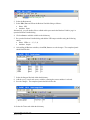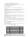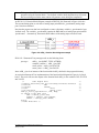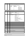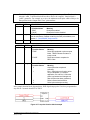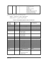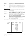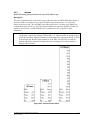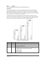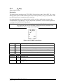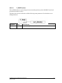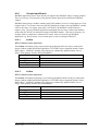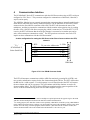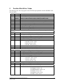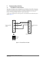
1
SCADAPack E Series
ISaGRAF User and Reference Manual
CONTROL
MICROSYSTEMS
SCADA products... for the distance
48 Steacie Drive
Kanata, Ontario
K2K 2A9
Canada
Telephone:
613-591-1943
Facsimile:
613-591-1022
Technical Support: 888-226-6876
888-2CONTROL
SCADAPack E Series ISaGRAF User and Reference Manual
©2000 - 2005 Control Microsystems Inc.
All rights reserved.
Printed in Canada.
Trademarks
TeleSAFE, TelePACE, SmartWIRE, SCADAPack, TeleSAFE Micro16 and
TeleBUS are registered trademarks of Control Microsystems Inc.
All other product names are copyright and registered trademarks or trade names
of their respective owners.
Material used in the User and Reference manual section titled SCADAServer
OLE Automation Reference is distributed under license from the OPC
Foundation.
E Series ISaGRAF User and Reference Manual
January 31, 2006
1
Table of Contents
1
PREFACE ...................................................................................................... 5
1.1
Scope............................................................................................................. 5
1.2
Assumed Knowledge ..................................................................................... 5
1.3
Target Audience............................................................................................. 5
1.4
References..................................................................................................... 5
2
OVERVIEW.................................................................................................... 6
2.1
Supported Languages.................................................................................... 6
2.2
Custom Functions .......................................................................................... 7
2.3
Custom I/O Connections ................................................................................ 7
3
COMPOSITION AND LAYOUT OF THIS MANUAL...................................... 8
4
INSTALLATION AND LICENSING................................................................ 9
4.1
System Requirements.................................................................................... 9
4.2
Installation ...................................................................................................... 9
4.3
Demo Mode ................................................................................................... 9
4.4
Licensing ...................................................................................................... 10
4.5
Activating License ........................................................................................ 10
4.6
Transferring an ISaGRAF License ............................................................... 14
4.6.1
Removing an ISaGRAF License ............................................................. 15
4.6.2
Install Sentinel Driver and Key................................................................ 16
E Series ISaGRAF User and Reference Manual
January 31, 2006
2
Notes
Additional information and changes are periodically made and will be incorporated in new editions
of this publication. Control Microsystems may make amendments and improvements in the
product(s) and/or program(s) described in this publication at any time.
Requests for technical information on software, E Series products and other publications should be
made to our agent (from whom you purchased our products/ publications) or directly to:
Technical; Support
Technical support is available from 8:00 to 18:30 (North America Eastern Time Zone). 1-888-2266876 [email protected]
Other products referred to in this document are registered trademarks of their respective companies,
and may carry copyright notices.
DISCLAIMER
CONTROL MICROSYSTEMS cannot warrant the performance or results you may obtain by using
the software or documentation. With respect to the use of this product, in no event shall CONTROL
MICROSYSTEMS be liable for any loss of profit or any other commercial damage, including but
not limited to special, incidental, consequential or other damages.
E Series ISaGRAF User and Reference Manual
January 31, 2006
3
Document Revisions
Revision
Date
Modification
Author
1.00
14 Sept, 2005
Initial release of SCADAPack E Series
ISaGRAF User and Reference Manual
KN
E Series ISaGRAF User and Reference Manual
January 31, 2006
4
1
1.1
Preface
Scope
This manual covers in details the SCADAPack E Series RTU1 ISaGRAF interface.
1.2
Assumed Knowledge
Familiarity with the Microsoft Windows recommended.
1.3
Target Audience
•
Systems Engineers
•
Commissioning Engineers
•
Maintenance Technicians
1.4
References
•
E Series Configuration Reference Manual
•
ICS Triplex ISaGRAF User Guide
•
E Series ISaGRAF ADS Flow Monitor Interface Manual
•
E Series ISaGRAF Technical Reference Manual
•
E Series ISaGRAF Custom Function Block Reference
•
E Series IO Connection Reference
•
E Series Configurator Reference
1
Also simply referred to as RTU in this document
E Series ISaGRAF User and Reference Manual
January 31, 2006
5
2
Overview
Control Microsystems IEC 61131-3 implementation enables the programming of SCADAPack E
Series RTU controller using the IEC 61131-3 programming languages. The programming
environment uses the ISaGRAF Workbench to create, load and debug IEC 61131-3 application
programs.
2.1
Supported Languages
ISaGRAF Workbench supports the five standard IEC 61131-3 programming languages and a sixth
language called Flow Chart. These languages may be mixed and matched within an application to
provide an optimum control strategy. The supported programming languages are described below.
Sequential Function Chart (SFC)
The Sequential Function Chart is a graphic language used to describe sequential operations in a
process. The process is graphically partitioned into a set of well-defined steps containing actions
performed using other languages such as ST, IL, LD and FBD. Steps are linked together with
conditional transitions. This language is useful for batch processes and process procedures such as
automatic startup and shut down.
Functional Block Diagram (FBD)
The Function Block Diagram is a graphic language used to build complex procedures from a library
of functions. Standard library functions such as math and logic may be combined with custom library
functions such as dial up modem control, HART Interface, PID controllers and Modbus master and
slave protocols to create Function Block Diagram application programs. A class of programs called
functions allows the creation of user functions that are not included in the library.
Ladder Diagram (LD)
Ladder Diagram is a graphic language combining contacts and coils to build logical discrete control
procedures. This language is identical to the relay ladder logic used by most programmable Logic
Controllers. Ladder Diagram contacts and coils may be used in the Function Block Diagram
language for discrete control of functions.
Structured Text (ST)
Structured Text is a high-level structured language, similar to Pascal and C, that is used for complex
procedures or calculation that cannot be easily implemented using graphic languages. Structured
Text is the default language used to describe actions within the steps of the Sequential Function
Chart language.
Instruction List (IL)
Instruction List is a low-level programming language, similar to assembly language that is used in
small applications that require fast execution. This language is typically used to optimize sections of
an application.
Flow Chart (FC)
Flow Chart is a graphic language that is used to describe sequential operations in an application. A
Flow Chart diagram is composed of actions to be performed and tests on the actions performed.
Actions and tests are connected by oriented links, representing data flow through the Flow Chart.
Tests determine the yes or no path of the data flow.
E Series ISaGRAF User and Reference Manual
January 31, 2006
6
2.2
Custom Functions
The standard ISaGRAF Workbench is enhanced with custom functions to support features provided
by the SCADAPack ES controllers. Custom functions provide support for dial up modems, HART
Interface modules, Store and Forward messaging, PID controllers and Modbus and DNP master and
outstation as well as peer-to-peer communications. Custom functions are integrated into the
ISaGRAF Workbench application programming environment.
2.3
Custom I/O Connections
SCADAPack ES, Allen Bradley and Idec modules or other Modbus devices are fully supported by
the enhanced ISaGRAF Workbench. The ISaGRAF Workbench I/O connection dialog is used to add
selected modules to the I/O connection list. Any combination of I/O modules may be selected up to
the maximum number of I/O points supported by the SCADAPack ES controller. Each input or
output point on a module is referenced with a variable name and, if required, a Modbus register
address. ISaGRAF program variables are updated continuously with data from the external I/O
modules.
E Series ISaGRAF User and Reference Manual
January 31, 2006
7
3
Composition and Layout of this Manual
This manual comprises of the following documents:
•
E Series ISaGRAF Quick Start Guide provides guides a new user through the creation of an
ISaGRAF project and application, compilation of an ISaGRAF program, connecting and
downloading the compiled ISaGRAF program to the RTU.
•
E Series ISaGRAF Technical Reference describes the interface between SCADAPack E Series
telemetry processors operating with DNP3 communication protocols and ISaGRAF target
software.
•
E Series ISaGRAF Function Block Reference describes in details all the custom function blocks
provided with this ISaGRAF installation.
•
E Series ISaGRAF I/O Connection Reference describes in details each individual I/O board and
equipment provided with this ISaGRAF installation. I/O board and equipments provide
ISaGRAF variables access to I/O data.
•
E Series ISaGRAF ADS Flow Reference details the ADS 3500 Flow Monitor driver
implementation for RTU.
•
E Series AGA Function Block Reference describes ISaGRAF function blocks that are used to
calculate the compressibility and the flow rate of a gas (AGA Report 8, AGA Report 3, AGA
Report 7, and AGA Report 9).
•
E Series Modbus PLC Interface Manual describes the RTU’s PLC device driver for MODBUS
and Open MODBUS/TCP protocols, its interface with ISaGRAF, and using it for
communicating with PLC and peripheral devices.
•
E Series DF1 PLC Interface Manual details the DF1 driver implementation for the RTU. This
manual provides a detailed explanation of the DF1 I/O board types referenced in the I/O
Connection Reference Manual.
•
E Series Idec PLC Interface Manual details the Idec driver implementation for the RTU. This
manual provides a detailed explanation of the Idec I/O board types referenced in the I/O
Connection Reference Manual.
E Series ISaGRAF User and Reference Manual
January 31, 2006
8
4
Installation and Licensing
This chapter covers the installation and licensing of the E Series ISaGRAF Workbench development
environment.
4.1
System Requirements
The ISaGRAF Workbench can be installed on any personal computer running Microsoft Windows®
98 / NT4 / 2000 or the XP Operating Systems with the following minimum requirements:
•
An Intel 80x86 or higher microprocessor.
•
8 Megabytes of conventional memory (16MB recommended)
•
20MB free disk space
•
640x480 VGA (800x600 VGA recommended)
•
Mouse (or other pointing device)
•
CD-ROM drive
•
An RS-232 serial communication port
Note:
4.2
A USB to RS-232 adapter will be required if PC or laptop is only equipped with a USB port.
Installation
To install the ISaGRAF Workbench
•
Insert the ISaGRAF CD into the CD-ROM.
•
From your Windows Start menu, select Run.
•
In the Run dialog, type d:\setup (if d is your CD-ROM drive) to run the installation executable.
Alternatively, use Windows Explorer to locate the CD-ROM drive, and locate the file setup.exe
in the root of the CD-ROM drive. Double click on the file to run the installation.
•
Follow the on-screen instructions to complete the Workbench installation.
If all default settings are chosen, the E Series ISaGRAF Workbench is installed in the
C:\ISAWIN\ESeries folder.
4.3
Demo Mode
When first installed ISaGRAF will run in the Demo Mode until a permanent license is installed. The
Demo version will run for a maximum of 30 days. The following message is displayed when a user
attempts to create or edit a project using the Demo version of ISaGRAF.
Note:
This dialog also appears when a hardware license is issued but the license key is not
connected.
E Series ISaGRAF User and Reference Manual
January 31, 2006
9
When running in the Demo Mode ISaGRAF does not support the following features:
•
Archiving or Restoring projects.
•
Exporting IEC 61131 programs to a library.
•
Exporting variables.
•
Downloading project source code in a target controller.
•
Uploading source code from a target controller.
You will need to permanently license your copy of ISaGRAF version 3.5 in order to enable the
above license features.
4.4
Licensing
The ISaGRAF Workbench 3.5 provides two types of licenses, a software license and a hardware
license. If you are using a Hardware License see the section 4.6.2 - Install Sentinel Driver and Key .
The process of enabling the software license consists of two steps:
•
Adding the License Component using the License Manager.
•
Activating the License through Control Microsystems via phone or email.
The ISaGRAF License Manager is used to install the ISaGRAF license, thus enabling the I/O
variable capacity used in projects and to enable the features not supported in the Demo Mode. The
License Manager is also used to:
•
Transfer a license from one personal computer to another.
•
Remove an ISaGRAF license from a personal computer.
4.5
Activating License
The ISaGRAF License Manager is used to install the license needed for full functionality of the
Workbench. The following procedure describes how to permanently license your copy of ISaGRAF
3.5.
•
Click on Windows Start | Programs | ISaGRAF for E Series | Licensing to launch the License
Manager.
E Series ISaGRAF User and Reference Manual
January 31, 2006
10
The Add Licensing tab displays the dialog necessary to add a permanent ISaGRAF license. In the
Configuration area of the dialog the Available Components section displays the licensing formats
available.
•
From the Available Components window click on ISaGRAF 3 Software License and then click
the Add button to move the selection to the Selected Components window. The following dialog
is displayed.
•
Select the number of IO variables shown on the ISaGRAF CD jewel case and select the OK
button. When the dialog closes the licensing window will display the license in the Selected
Components column as shown below.
E Series ISaGRAF User and Reference Manual
January 31, 2006
11
•
Click the Proceed button. New user codes are created and a prompt to call or email CMI is
displayed.
•
Click the Yes button to automatically generate an License Request email as shown below.
E Series ISaGRAF User and Reference Manual
January 31, 2006
12
Enter the fields displayed and send the email. If you wish you can phone Customer Support at 888267-2232 for to complete the license activation over the phone.
If the activation request was sent via email, you will receive a return email containing the registration
keys needed to activate your license. There are two sets of four registration keys that need to be
entered in the License Manager.
•
Enter the first four registration keys in the appropriate entry windows of the Registration
section of the dialog.
E Series ISaGRAF User and Reference Manual
January 31, 2006
13
•
Click the Register button and OK on the next dialog prompting to enter the second set of
Registration keys
•
Enter the second set of registration keys are entered click the Register button.
The following dialog is then displayed to indicate the license has been enabled.
•
4.6
Click the OK button to close the Registration Manager.
Transferring an ISaGRAF License
An ISaGRAF license can be transferred from one PC to another. Both PC’s must contain an
installation of the ISaGRAF workbench. Once the license has been transferred, the ISaGRAF
installation on the source PC will continue operating in Demo mode for 30 days after which the
application becomes non-functional. On the target PC however, full functionality will be enabled
once the license transfer process is complete.
Transferring an ISaGRAF license from one PC to another comprises of three main steps:
•
Creating a license transfer disk on the target PC.
•
Transferring the ISaGRAF license from the source PC to the transfer disk.
•
Installing the ISaGRAF license from the transfer disk to the target PC.
To transfer an ISaGRAF license from one PC to another PC:
1.
From the Target PC, prepare the license transfer disk as follows:
• Select Start | Programs | ISaGRAF for E Series | Licensing to launch the License
Manager dialog on the target PC.
• Select the Transfer Licensing tab on the License Manger dialog.
• From the drop down dialog, select the drive holding the transfer disk. This drive may be any
medium, such as diskette, USB memory stick, or a network disk drive.
E Series ISaGRAF User and Reference Manual
January 31, 2006
14
•
Click on the Create Transfer Disk button. The license disk is created.
• Remove the transfer disk from the target PC.
2. Transfer the license from the source PC (currently licensed computer) to the license transfer
disk created in step 1 as follows:
• Insert the license disk into the source PC’s peripheral inlet port.
• Select Start | Programs | ISaGRAF for E Series | Licensing to launch the License
Manager dialog on the source PC.
• Select the Transfer Licensing tab on the License Manger dialog.
• From the drop down dialog, select the drive holding the transfer disk created in step 1.
• Click the Transfer License to Disk button. The license is removed from the source PC and
copied onto the license transfer disk.
• Remove the license transfer disk from the source PC.
3. Install the license onto the target PC.
• Insert the disk containing the ISaGRAF license into the target PC’s drive.
• Select Start | Programs | ISaGRAF for E Series | Licensing to launch the License
Manager dialog on the target PC.
• Select the Transfer Licensing tab on the License Manger dialog.
• From the drop down dialog, select the drive holding the transfer disk containing the
ISaGRAF license copied from step 2.
• Click on the Complete Transfer button to transfer the license onto the target PC.
4.6.1
Removing an ISaGRAF License
To permanently remove the ISaGRAF license:
•
Select Start | Programs | ISaGRAF for E Series | Licensing to launch the License Manager
dialog.
•
Select the Removing Licensing tab on the License Manager
•
From the License Components box, click on ISaGRAF 3 Software License (Active)– WDL and
then click the Add button to move the selection to the Selected Components window.
•
Click the Proceed button and the following dialog is displayed.
•
Click the Yes button to automatically generate an email as shown below.
E Series ISaGRAF User and Reference Manual
January 31, 2006
15
Enter the fields displayed and send the email. If you wish you can phone Customer Support at 888267-2232 for to complete the license removal over the phone.
If the license removal request was sent via email, you will receive a return email containing the
registration keys needed to remove your license. There are two sets of four registration keys that
need to be entered in the License Manager.
There are four registration keys that need to be entered in the License Manager.
•
Enter the four registration keys in the appropriate entry windows of the Registration section of
the dialog.
•
Click the Register button and the following dialog is displayed indicating the license has been
removed.
4.6.2
Install Sentinel Driver and Key
If you are using a hardware key for your license you will need to connect the hardware key to any
parallel port on your PC, or a USB port if you have a USB key, and install the Sentinel driver for the
key. The following procedure describes the steps required to install the hardware key and Sentinel
driver.
•
Connect the hardware key to any parallel port, or USB port, on your PC.
E Series ISaGRAF User and Reference Manual
January 31, 2006
16
•
Insert the ISaGRAF CD in your CD-ROM drive.
•
From the Windows start menu select Run.
•
Enter d: \ISaGRAF Workbench\sentinel\SSD5411-32bit.EXE (where d is your CD-ROM
drive) and click OK.
•
In the Sentinel Driver Setup Program window click on the Functions menu and select Install
Sentinel Driver.
For further information refer to the Readme.txt file in the d:\sentinel folder on the CD.
E Series ISaGRAF User and Reference Manual
January 31, 2006
17
SCADAPack E Series
ISaGRAF Quick Start Guide
CONTROL
MICROSYSTEMS
SCADA products... for the distance
48 Steacie Drive
Kanata, Ontario
K2K 2A9
Canada
Telephone:
613-591-1943
Facsimile:
613-591-1022
Technical Support: 888-226-6876
888-2CONTROL
E Series ISaGRAF Quick Start Guide
©2000 - 2005 Control Microsystems Inc.
All rights reserved.
Printed in Canada.
Trademarks
TeleSAFE, TelePACE, SmartWIRE, SCADAPack, TeleSAFE Micro16 and
TeleBUS are registered trademarks of Control Microsystems Inc.
All other product names are copyright and registered trademarks or trade names
of their respective owners.
Material used in the User and Reference manual section titled SCADAServer
OLE Automation Reference is distributed under license from the OPC
Foundation.
E Series ISaGRAF Quick Start Guide
January 19, 2006
1
Table of Contents
1
PREFACE ...................................................................................................... 5
1.1
Scope............................................................................................................. 5
1.2
Purpose.......................................................................................................... 5
1.3
Assumed Knowledge ..................................................................................... 5
1.4
Target Audience............................................................................................. 5
1.5
References..................................................................................................... 5
2
OVERVIEW.................................................................................................... 6
3
PROGRAMMING WITH ISAGRAF................................................................ 7
3.1
Hardware Requirements ................................................................................ 7
3.2
Creating an ISaGRAF Application.................................................................. 7
3.3
Defining Dictionary Variables ......................................................................... 9
3.4
Connecting Variables to Physical I/O ........................................................... 11
3.5
Compilation of the Source Code .................................................................. 12
3.6
Downloading the Compiled Program onto the Target RTU .......................... 12
3.6.1
Configure the SCADAPack ES ISaGRAF Port ....................................... 12
3.6.2
Configure the ISaGRAF PC-PLC Link .................................................... 13
E Series ISaGRAF Quick Start Guide
January 19, 2006
2
Notes
Additional information and changes are periodically made and will be incorporated in new editions
of this publication. Control Microsystems may make amendments and improvements in the
product(s) and/or program(s) described in this publication at any time.
Requests for technical information on software, E Series products and other publications should be
made to our agent (from whom you purchased our products/ publications) or directly to:
Technical; Support
Technical support is available from 8:00 to 18:30 (North America Eastern Time Zone). 1-888-2266876 [email protected]
Other products referred to in this document are registered trademarks of their respective companies,
and may carry copyright notices.
DISCLAIMER
CONTROL MICROSYSTEMS cannot warrant the performance or results you may obtain by using
the software or documentation. With respect to the use of this product, in no event shall CONTROL
MICROSYSTEMS be liable for any loss of profit or any other commercial damage, including but
not limited to special, incidental, consequential or other damages.
E Series ISaGRAF Quick Start Guide
January 19, 2006
3
Document Revisions
Revision
Date
Modification
Author
1.00
20 October
2005
Initial release of E Series ISaGRAF Quick
Start Guide
KN
E Series ISaGRAF Quick Start Guide
January 19, 2006
4
1
1.1
Preface
Scope
This document is intended as a quick start guide to help new users create an ISaGRAF application,
connect and download the application to a SCADAPack ES or ER controller in a timely fashion.
The simple tasks presented in this guide therefore do not include important user information
necessary for the control of real life applications. As such, this introductory document should be
used in conjunction with the ISaGRAF Workbench User Guide and the E Series ISaGRAF Technical
Reference Manuals.
1.2
Purpose
The purpose of this document is to provide a quick guide for creating an ISaGRAF application,
connecting and downloading the application onto a SCADAPack ES controller.
1.3
Assumed Knowledge
Exposure to the ISaGRAF Workbench is recommended.
1.4
Target Audience
•
Systems Engineers
•
Commissioning Engineers
•
Maintenance Technicians
1.5
References
•
E Series Configuration Reference Manual
•
CJ International ISaGRAF Manuals
E Series ISaGRAF Quick Start Guide
January 19, 2006
5
2
Overview
This document is intended as a guide to help new users configure, program and operate the
SCADAPack ES controller in a timely fashion. It is not meant to be a substitute for the ISaGRAF
IEC61131 and SCADAPack ES Controller manuals, but rather as a companion to these manuals.
For a thorough treatment of IEC 61131-11 ISaGRAF fundamentals, it is recommended that the user
consult the E Series ISaGRAF Technical Reference Manuals and/or the ICS Triplex ISaGRAF User
Guide.
In this manual, the user is guided through the task of creating a sample ISaGRAF Function Block
Diagram program, compilation of the program, connecting to the SCADAPack ES RTU and
downloading the compiled program onto the target kernel.
E Series ISaGRAF Quick Start Guide
January 19, 2006
6
3
Programming with ISaGRAF
In this section, the user will be guided through creating a simple ISaGRAF application and
downloading the compiled program to the RTU target kernel.
The process of creating an ISaGRAF application comprises of the following steps:
•
Creating an ISaGRAF application.
•
Defining dictionary variables.
•
Connecting to external I/O
•
Compiling and making the source code available for download to the target controller.
•
Connecting and downloading the ISaGRAF application onto the target controller.
•
Monitoring the ISaGRAF program variables online.
Each of the above tasks will be covered in the remaining section of this manual.
3.1
Hardware Requirements
The following hardware items are recommended to perform the tasks in this manual:
•
CD containing the E Series Configurator Software.
•
SCADAPack E Series controller – Make note of nominal operational voltage.
•
A 12VDC/1.1A or 24 VDC/0.55A power supply depending on controller requirement.
•
RJ-11 to DB-9 crossed cable or CMI part # 297324.
•
Windows PC or laptop with the following minimum hardware requirements:
•
•
•
•
•
•
•
•
•
Note:
3.2
Intel (or equivalent) 386 CPU, 33MHz (486 CPU recommended)
16MB RAM (32MB recommended)
4MB free disk space
Microsoft Windows® 98 / NT4 / 2000 / XP Operating Systems
640x480 VGA (800x600 VGA recommended)
Mouse (or other pointing device)
CD-ROM drive
One (1) RS-232 serial communication port
Ethernet port (optional)
A USB to RS-232 adapter will be required if PC or laptop is only equipped with a USB port.
Creating an ISaGRAF Application
In this section, a sample ISaGRAF application which cycles through the first four digital output
channels on the SCADAPack ES at a controlled frequency will be created and downloaded to the
controller. The frequency at which the output LEDs are cycled is controlled by a potentiometer
attached to one of the analog input ports of the SCADAPack ES.
1.
Launch the ISaGRAF workbench by clicking on ISaGRAF for E Series | Projects from the
Windows programs menu.
2. Click on File | New from the Project Management menu bar to create a new application.
E Series ISaGRAF Quick Start Guide
January 19, 2006
7
3.
4.
5.
6.
Enter a project name e.g. Proj1 and click on OK to close the dialog.
Double click on the project name e.g. Proj1 to open the project’s program window.
Select File | New from the program menu bar to create a new program.
Specify a program name e.g. prog1 and select FBD: Function Block Diagram from the
Language drop down menu in the New Program dialog. Leave the style parameter at the default
Begin: Main Program.
7. Click on OK to and double click on the newly created program name e.g prog1 to open the
FBD/QL editor.
Note:
8.
All subsequent references to this sample program will be done using ‘prog1.’
Create the sample FBD program exactly as captured in the screen shot below.
E Series ISaGRAF Quick Start Guide
January 19, 2006
8
3.3
Defining Dictionary Variables
All variables defined within an ISaGRAF program must exist in the dictionary for the program to
compile successfully. The following variables have been used in the above FBD program.
Variable Name
speed_control
counter
SW1
LED1
LED2
LED3
LED4
led_frequency
Type
Integer (Analog)
Integer
Boolean
Boolean
Boolean
Boolean
Boolean
Timer
Attribute
Input
Internal
Input
Output
Output
Output
Output
Internal
To define the above variables in the dictionary do the following:
1. From the programs window, select File | Dictionary or click on the dictionary icon
toolbar.
E Series ISaGRAF Quick Start Guide
January 19, 2006
from the
9
2. Select the Boolean tab.
3. Select Edit | New and fill out the Boolean Variable dialog as follows:
• Name: SW1
• Attribute: Input
Alternatively, you can double click on a blank white space under the Boolean Variable ‘page’ to
open the Boolean Variable dialog.
4. Click on Store to add this variable to the dictionary.
5. Re-open the Boolean Variable dialog and add the LED output variables using the following
entries.
• Name: LEDx (x = 1, 2, 3, 4)
• Attribute: Output
6. After adding all Boolean variables, select File | Save to save the changes. The completed panel
should look like this
7. Select the Integers/Real tab within the dictionary.
8. Add the speed_control and counter variables, ensuring the correct attribute is selected.
9. Save the changes. The completed panel should look like this
10. Select the Timers tab within the dictionary.
E Series ISaGRAF Quick Start Guide
January 19, 2006
10
11. Add the led_frequency variable also ensuring the correct attribute is selected.
12. Save the changes.
13. After all variables have been entered, close the dictionary.
3.4
Connecting Variables to Physical I/O
Before compiling the application, the FBD program variables with input or output type attributes
have to be connected to the physical I/O. This is done as follows:
.
1. Select Project | I/O Connection from the project’s program menu bar or click on the icon
2. Double click on the first empty slot 0 in the I/O connection window to view the list of available
I/O drivers.
3. Select the board /Equipment board type labeled rtu16di: RTU 16 Digital Input Board from the
list.
4. Click OK.
This board type provides and ISaGRAF application access to 16 physical digital inputs.
5. Double on terminal connector 1 directly underneath board_address = 1 to open the Connect I/O
Channel # dialog.
6. Select the variable SW1 from the Free list and click on the Connect button to attach this
variable to the digital input channel 1 on the SCADAPack ES controller.
7. Click on Close to return to the I/O connection window..
E Series ISaGRAF Quick Start Guide
January 19, 2006
11
8. Double click on the second empty slot 1 in the I/O connection window and select the rtu16do:
RTU 16 Digital Output Board.
9. Click on OK.
10. Double click on terminal connector 1 directly underneath board_address = 1 to open the
Connect I/O Channel # dialog.
11. Select the variable LED1 from the Free list and click on the Connect button to attach this
variable to the digital output channel 1 on the SCADAPack ES controller.
12. Click on Next and Connect to add the remaining digital output variables.
13. Close the dialog.
14. Follow the same procedure above and connect the integer variable speed_control to an analog
input channel 1 using the rtu1ai: RTU 1 Analog Input Board module.
from the toolbar to save changes to the dictionary.
15. Click on
16. Close the dictionary.
3.5
Compilation of the Source Code
After completion of the source code (program, dictionary variables and I/O connection), the code is
compiled for errors. If no errors are found, the ISaGRAF MAKE utility converts the source code
into a form suitable for download onto the selected target controller.
1.
2.
3.
4.
Select Make | Compiler options from PROJ1’s program menu bar.
Highlight ISA86M: TIC Code for Intel and click on Select.
Click on OK to save the changes.
Click on OK on the next prompt indicating that all programs will be verified during the next
make command. All other parameters can be left at default settings.
from the toolbar.
5. Select Make | Make application from PROJ1’s program menu or click on
6. If no errors are detected, click on Exit from the Code Generator dialog. If errors are presented, it
may be necessary to verify the source code.
3.6
Downloading the Compiled Program onto the Target RTU
Once the ISaGRAF program has been successfully compiled into a form suitable for download onto
the target RTU using the ‘Make’ command, it then suffices to download the program onto the target
RTU for execution. First, a communication link between the ISaGRAF Workbench and the RTU
target kernel must be established.
The SCADAPack ES controller supports a serial or Ethernet communication link to the ISaGRAF
Workbench. In this project, a serial communication link will be used to enable communication
between the ISaGRAF Workbench and the SCADAPack ES RTU.
To connect to the SCADAPack ES via a serial connection, one of the RTU communication ports
must be set for “ISaGRAF’.
3.6.1
Configure the SCADAPack ES ISaGRAF Port
1. Select Start | Programs | Control Microsystems | E Series Configurator | E Series
Configurator to launch this application.
2. Click on Communication | Communication Device from the E Series menu bar.
3. Alternatively, click on the icon
communication device.
E Series ISaGRAF Quick Start Guide
January 19, 2006
from the E Series Configurator toolbar to select the
12
4.
5.
6.
7.
8.
Ensure that the RS-232 (Serial) COM port is selected.
Click on OK to close the dialog.
Select the Ports page.
Connect the PC to COM port 1 of the RTU.
Ensure that the Remote DNP Address in the Comms Control panel is correct and click on the
Read button.
Note:
If communication problems are encountered at this point, such as if the yellow Comms status
light on the bottom right hand corner of the Ports page remains lit, please refer to the E
Series Configurator User Manual or the SCADAPack ES Quick Start Guide.
9. Ensure that Port 0 Function is set to ISaGRAF as shown in the screen capture above. Also
make a note of the Baud Rate and Data Mode parameters.
10. Select Communications | Disconnect from the E Series Configurator menu bar to free the PC
COM port.
Note:
3.6.2
This step is necessary to allow another application, ISaGRAF for example, to share the
COM port.
Configure the ISaGRAF PC-PLC Link
1. On the RTU, remove the serial cable from Port 1 and plug it into Port 0, the ISaGRAF port.
E Series ISaGRAF Quick Start Guide
January 19, 2006
13
2. Within ISaGRAF click on Debug | Link Setup from PROJ1’s Programs window to launch the
PC-PLC link parameters dialog..
from the program window toolbar to launch this dialog.
3. Alternatively, click on the icon
4. Within the PC-PLC link parameters dialog,
1. Select the PC serial port connected to the Port 0 of the RTU from the
Communication Port drop down menu.
2. Click on the Setup button.
3. Ensure that baud rate and other link properties match those noted in step 9 above.
The baud rate may have to be changed from 19200 to 9600.
4. In the figure below, the RTU is connected to COM 2 of the PC and the link
properties have been set to match those in the figure above.
5. Click on OK on the Serial link parameters dialog to save the changes and close the
dialog.
6. Click on OK on the PC-PLC link parameters dialog to save the changes and close
the dialog.
5. From PROJ1’s program window click on Debug | Debug.
Alternatively, click on the icon
from the program window toolbar to launch this dialog.
6. The ISaGRAF debugger window will open with the message No application as shown below.
This indicates that there is currently no application running in the controller.
If presented with a different status message such as Disconnected or Logging… Cannot open COM2
communication port, double check the PC-PLC parameters.
7. From the Debugger menu bar, click on File | Download.
Alternatively, click on the icon
process.
E Series ISaGRAF Quick Start Guide
January 19, 2006
from the program window toolbar to initiate the download
14
8. Ensure that ISA86M: TIC code for Intel is selected in the Download dialog and click on
Download.
9. Observe the download progress on the status bar.
After the download is complete, toggle the switch attached to digital input channel 1 of the
SCADAPack ES and observe the LEDs on the controller digital output channels 1- 4 cycle in a
round-robin fashion. The Debugger status bar will display RUN while the program executes as
shown below.
10. The application variables may now be viewed in real time by opening the dictionary and
observing the real time value of one of the variables.
11. Stop the running program by selecting File | Stop Application from the Debugger menu bar.
Alternatively, click on the icon
running.
from the program window toolbar to stop the program from
12. The LEDs will stop turning on and off in a cyclic fashion.
This completes the exercise. Note that this simple exercise does not exhaust the capabilities of the
SCADAPack ES controller. Please refer to the reference manuals that accompany your controller
unit for details on the controller operation and capabilities.
E Series ISaGRAF Quick Start Guide
January 19, 2006
15
SCADAPack E Series
ISaGRAF Technical Reference Manual
CONTROL
MICROSYSTEMS
SCADA products... for the distance
48 Steacie Drive
Kanata, Ontario
K2K 2A9
Canada
Telephone:
613-591-1943
Facsimile:
613-591-1022
Technical Support: 888-226-6876
888-2CONTROL
E Series ISaGRAF Technical Reference Manual
©2006 Control Microsystems Inc.
All rights reserved.
Printed in Canada.
Trademarks
TeleSAFE, TelePACE, SmartWIRE, SCADAPack, TeleSAFE Micro16 and
TeleBUS are registered trademarks of Control Microsystems Inc.
All other product names are copyright and registered trademarks or trade names
of their respective owners.
Material used in the User and Reference manual section titled SCADAServer
OLE Automation Reference is distributed under license from the OPC
Foundation.
E Series ISaGRAF Technical Reference Manual
February 7, 2006
1
Table of Contents
1
PREFACE ...................................................................................................... 7
1.1
Scope............................................................................................................. 7
1.2
Purpose.......................................................................................................... 7
1.3
Assumed Knowledge ..................................................................................... 7
1.4
Target Audience............................................................................................. 7
1.5
References..................................................................................................... 7
2
OVERVIEW.................................................................................................... 8
2.1
Terminology ................................................................................................... 8
2.2
ISaGRAF Workbench Software...................................................................... 8
2.2.1
ISaGRAF Serial Communications............................................................. 8
2.2.2
MODBUS Serial Communications ............................................................ 9
2.2.3
ISaGRAF Remote Access ........................................................................ 9
2.3
SCADAPack E Series ISaGRAF Target....................................................... 10
2.4
Target Scanning Cycle................................................................................. 10
2.4.1
Continuous Scanning.............................................................................. 11
2.4.2
Cycle Time Scanning .............................................................................. 11
2.4.3
High Priority Scanning ............................................................................ 13
2.5
Target Memory usage .................................................................................. 13
3
RTU PLC FUNCTIONALITY........................................................................ 14
3.1
Input Scanning ............................................................................................. 14
3.1.1
Binary Inputs........................................................................................... 14
3.1.2
Analog Inputs.......................................................................................... 14
3.2
Output Updates ............................................................................................ 14
3.2.1
Binary Outputs ........................................................................................ 14
3.2.2
Analog Outputs ....................................................................................... 14
3.3
Language Types .......................................................................................... 15
3.4
Data Types................................................................................................... 15
3.5
Operators ..................................................................................................... 16
3.6
Conversion Tables ....................................................................................... 16
3.7
On-line Modification ..................................................................................... 16
E Series ISaGRAF Technical Reference Manual
February 7, 2006
2
3.8
Application Storage ...................................................................................... 17
3.9
I/O Locking................................................................................................... 17
3.10
Message variables ....................................................................................... 18
3.11
Retained variables ....................................................................................... 18
3.12
Second ISaGRAF Kernel Features .............................................................. 19
4
I/O INTERFACES ........................................................................................ 20
4.1
Physical I/O .................................................................................................. 20
4.2
Derived Data ................................................................................................ 20
4.3
ISaGRAF I/O Boards.................................................................................... 21
4.3.1
Digital Input Boards ................................................................................ 22
4.3.2
Digital Output Boards.............................................................................. 22
4.3.3
Analog Input Boards ............................................................................... 22
4.3.4
Analog Output Boards ............................................................................ 23
4.3.5
Counter Input Boards.............................................................................. 23
4.3.6
SCADAPack ER I/O Boards ................................................................... 24
4.4
Slave PLC I/O Boards .................................................................................. 25
4.4.1
Input Boards ........................................................................................... 27
4.4.2
Output Boards......................................................................................... 28
4.4.3
Board Status ........................................................................................... 28
5
ISAGRAF VARIABLE / PDS DNP3 POINT INTERACTION........................ 34
6
ISAGRAF ANALOG I/O BOARDS / DNP3 REPRESENTATION &
CONVERSION........................................................................................................ 35
7
ISAGRAF OPERATE FUNCTION ............................................................... 36
7.1
Using ISaGRAF Operate Functions with Conversion Tables ....................... 37
8
ISAGRAF MODBUS LINK........................................................................... 39
8.1
MODBUS Operation..................................................................................... 39
8.2
MODBUS Communication ........................................................................... 40
8.3
ISaGRAF / MODBUS Mapping .................................................................... 40
9
REMOTE ISAGRAF ACCESS..................................................................... 42
9.1
Application File Transfer .............................................................................. 42
E Series ISaGRAF Technical Reference Manual
February 7, 2006
3
9.2
DNP3 Communications ................................................................................ 42
9.3
TCP/IP Communications.............................................................................. 45
9.3.1
ISaGRAF Workbench Ethernet Settings ................................................. 45
9.3.2
ISaGRAF TCP/IP Communications Server............................................. 46
10
ISAGRAF TROUBLESHOOTING & ERROR CODES ................................ 47
10.1
Error Types .................................................................................................. 47
10.2
Error Summary............................................................................................. 47
10.3
Error Descriptions ........................................................................................ 49
11
ISAGRAF UNSUPPORTED FEATURES .................................................... 56
Index of Figures
Figure 2-1 Target Scanning Cycle ..................................................................................... 10
Figure 3-1: Online modification of an ISaGRAF Program.... Error! Bookmark not defined.
Figure 3-2: Online Modification ......................................................................................... 18
Figure 4-1 ISaGRAF I/O boards ........................................................................................ 21
Figure 7-1 Example Operate command............................................................................. 37
Figure 9-1: The E Series Configurator PC-PLC Link Option............................................. 43
Figure 9-2: Remote ISaGRAF Communication................................................................. 44
Figure 9-3: ISaGRAF Workbench Ethernet Settings ........................................................ 45
Figure 9-4: TCP/IP ISaGRAF Communication.................................................................. 46
E Series ISaGRAF Technical Reference Manual
February 7, 2006
4
Notes
Additional information and changes are periodically made and will be incorporated in new editions
of this publication. Control Microsystems may make amendments and improvements in the
product(s) and/or program(s) described in this publication at any time.
Requests for technical information on software, E Series products and other publications should be
made to our agent (from whom you purchased our products/ publications) or directly to:
Technical; Support
Technical support is available from 8:00 to 18:30 (North America Eastern Time Zone). 1-888-2266876 [email protected]
Other products referred to in this document are registered trademarks of their respective companies,
and may carry copyright notices.
DISCLAIMER
CONTROL MICROSYSTEMS cannot warrant the performance or results you may obtain by using
the software or documentation. With respect to the use of this product, in no event shall CONTROL
MICROSYSTEMS be liable for any loss of profit or any other commercial damage, including but
not limited to special, incidental, consequential or other damages.
E Series ISaGRAF Technical Reference Manual
February 7, 2006
5
Document Revisions
Revision
Date
Modification
Author
1.10
19 January 2006
Incorporated Dec 19. 2005 changes
KN
1.00
20 October 2005
Initial release of E Series ISaGRAF
Technical Reference Manual
KN
E Series ISaGRAF Technical Reference Manual
February 7, 2006
6
1
1.1
Preface
Scope
This document describes the interface between SCADAPack E Series RTU1’s processors operating
with DNP3 communication protocols and the ISaGRAF target software.
1.2
Purpose
The purpose of this document is to describe in details the interface between SCADAPack E Series
RTU’s processors operating with DNP3 communication protocols and the ISaGRAF target software.
It is assumed that the reader is familiar with the ISaGRAF workbench software. For more
information about the ISaGRAF program environment, the see the ISaGRAF Workbench Users
Guide which contains the ISaGRAF Language Reference and ISaGRAF Target User's Guide.
Additional programming options specific to the E Series controllers can be found in the E Series
ISaGRAF Function Blocks Reference manual.
Note that the ISaGRAF Target User's Guide included with the ISaGRAF Workbench manual is not
dedicated to any particular ISaGRAF target and describes general concepts. The material covered in
this manual together with the E Series ISaGRAF Function Blocks Reference manual therefore
supplements the ISaGRAF Target User's Guide for it deals exclusively with the implementation of
the ISaGRAF Target kernel on a Control Microsystems E Series processor.
Specific technical reference information pertaining to ISaGRAF Function Blocks used with
SCADAPack E Series RTU’s can be found in the E Series ISaGRAF Function Blocks Reference
manual.
1.3
Assumed Knowledge
Familiarity with the ISaGRAF Workbench is strongly recommended.
1.4
Target Audience
•
Systems Engineers
•
Commissioning Engineers
•
Maintenance Technicians
1.5
References
•
E Series Configuration Reference Manual
•
CJ International ISaGRAF Manuals
1
Also referred to simply as ‘RTU'
E Series ISaGRAF Technical Reference Manual
February 7, 2006
7
2
Overview
This document describes the interface between SCADAPack E Series RTU operating with DNP3
communication protocols and ISaGRAF target software. The ISaGRAF target kernels execute on the
RTU and are built in to the operating system firmware. The ISaGRAF Workbench executes on a PC
and provides application generation, transferring and debugging through connection to the target by
serial or network communications.
2.1
Terminology
The SCADAPack E Series RTU uses ISaGRAF target software within the RTU’s multi-tasking
environment. The RTU’s have a fixed amount of on-board I/O on the main unit but may be
connected to remote I/O units via serial or Ethernet communications.
2.2
ISaGRAF Workbench Software
An ISaGRAF application can be loaded, configured, debugged on the SCADAPack E Series RTU
from a standard PC running the ISaGRAF Workbench if there is some physical connection between
the PC and the RTU. Serial and Ethernet or TCP/IP communication facilities are provided by the
RTU to allow different options of connection from a standard PC.
The ISaGRAF Workbench software is used to create, manage and simulate IEC61131-3 ISaGRAF
applications. The ISaGRAF Workbench debugger transfers ISaGRAF application programs to the
target and provides application-debugging facilities. ISaGRAF Workbench is compatible with
Windows 95/98, NT, 2000 and XP. For more information on the ISaGRAF Workbench, refer to the
ISaGRAF Workbench User’s Guide.
The following sections describe the various connection options that are available between the
ISaGRAF Workbench and SCADAPack E Series RTU's.
2.2.1
ISaGRAF Serial Communications
The ISaGRAF Workbench debugger operates with the SCADAPack E Series RTU’s on an RTU
serial port configured as “ISaGRAF”. Operation is supported for RS232, RS422 and RS485.
Note:
A maximum of one RTU serial port may be configured as “ISaGRAF” for local connection
to an ISaGRAF Workbench debugger.
An ISaGRAF application previously loaded into the RTU (via Workbench or the E Series
Configurator) will execute on the RTU regardless of whether an “ISaGRAF” port is configured.
The “ISaGRAF” port on an RTU can also be used for other purposes:
•
ISaGRAF “Diagnosis/Monitoring Tool”
•
MODBUS RTU Slave Protocol communications
•
RTU Command Line and Diagnostics “Shell”
For more information on MODBUS RTU protocol communications see Section 8 - ISaGRAF
MODBUS Link.
Operation of the Command Line Shell allows an ASCII terminal to be connected to the RTU
“ISaGRAF” port. Entering <Enter> <Enter> <Enter> from the terminal activates the command line
shell. Note that the terminal communications settings must match those on the RTU’s “ISaGRAF”
port. Once activated, the RTU Command Line prompt is displayed, and ISaGRAF Workbench
Communications are disabled on this port. RTU diagnostics and all command line facilities are
E Series ISaGRAF Technical Reference Manual
February 7, 2006
8
available. This functionality is the same as that provided by a configured “Cmd Line” port, without
re-configuring the RTU.
To return from Command Line Shell back to ISaGRAF Workbench communications, enter the
command line “BYE” command and disconnect the ASCII terminal. For more information on the
Command Line RTU facilities see the E Series Operation Reference Manual.
2.2.2
MODBUS Serial Communications
As described in the previous section, the ISaGRAF Workbench port can be used for MODBUS serial
communications. In addition to this, a second serial port can be configured on the SCADAPack E
Series RTU to provide separate MODBUS communications. An RTU serial port configured as
“ISaGRAF 2” supports the same Modbus operations as the standard ‘ISaGRAF’ Workbench port but
does not support the RTU Command line and Diagnostic shell. Note that the SCADAPack E Series
also supports a native MODBUS Slave driver that does NOT require ISaGRAF. Refer to the E Series
Modbus PLC Interface document for more information.
A maximum of one RTU serial port may be configured in “ISaGRAF” mode. However, both the
“ISaGRAF” and “ISaGRAF 2” ports may be used simultaneously, and either port may be used to
communicate with either of the E Series RTU ISaGRAF target applications. Operation is supported
for RS232, RS422 and RS485. For example, the following scenarios are possible:
•
ISaGRAF Workbench on “ISaGRAF” port to Target 1, Modbus master on “ISaGRAF 2” port to
Target 1
•
Modbus master on “ISaGRAF” port to Target 1, second Modbus master on “ISaGRAF 2” port to
Target 1
•
Modbus master on “ISaGRAF” port to Target 1, second Modbus master on “ISaGRAF 2” port to
Target 2
•
Modbus master on “ISaGRAF” port to Target 2, ISaGRAF “Diagnosis/Monitoring Tool” on
“ISaGRAF 2” port to Target 2, etc.
An ISaGRAF application previously loaded in the RTU (via the Workbench or the E Series
Configurator) maps data to Modbus registers accessible via the “ISaGRAF” or “ISaGRAF 2” port(s).
Note:
The “ISaGRAF 2” port does NOT support RTU Command Line and Diagnostics “Shell”
command.
For more information on MODBUS RTU protocol communications see Section 8 - ISaGRAF
MODBUS Link.
2.2.3
ISaGRAF Remote Access
The SCADAPack E Series RTU provides various remote access facilities for ISaGRAF. These are:
•
ISaGRAF application file transfer
•
ISaGRAF application file transfer via FTP
•
ISaGRAF workbench communication via DNP3
•
ISaGRAF workbench communication via TCP/IP
Each of these facilities is further described in Section 9 - Remote ISaGRAF Access.
E Series ISaGRAF Technical Reference Manual
February 7, 2006
9
2.3
SCADAPack E Series ISaGRAF Target
The SCADAPack E Series RTU is equipped with ISaGRAF target kernel software. This allows the
RTU to perform PLC control functions using the IEC 61131-3 international standard. The control
functions provided by ISaGRAF targets are completely autonomous of any supervisory (SCADA
Master) system or communications network (e.g. DNP3). The ISaGRAF application operates on the
RTU regardless of the state of remote communications. The ISaGRAF target supports ISaGRAF
Workbench versions 3.20 and later.
The SCADAPack E Series RTU firmware supports the simultaneous execution of up to two
ISaGRAF target kernels on the same RTU. This allows up to two independent ISaGRAF
applications to execute simultaneously on the same RTU. The two ISaGRAF targets within the RTU
have ISaGRAF Slave addresses of 1 and 2 respectively. The Workbench "Slave Number"
communications parameter must be set to match the E Series RTU’s ISaGRAF Slave address for the
appropriate target kernel prior to connecting the ISaGRAF Workbench debugger to the RTU. Note
that both ISaGRAF targets are activated by default, i.e. there is no additional configuration required
to activate the second ISaGRAF target.
The status (running or halted) of an ISaGRAF application on each target kernel can be obtained from
the E Series Configurator software or via separate ISaGRAF Application Halted DNP3 binary points
50100 and 50101. These binary points are part of the DNP3 system points dedicated to providing
the status of the RTU. . For more information see the E Series DNP3 Technical Reference Manual.
An RTU port selected for ‘ISaGRAF’ communications mode can also support MODBUS Slave
Protocol communications. For more information see Section 8 - ISaGRAF MODBUS Link.
The SCADAPack E Series RTUs are based on Intel processors. The ISaGRAF Workbench software
generates target independent code (TIC) for Intel, Motorola and PC Simulation. To use ISaGRAF
applications with the SCADAPack E Series RTU, ISaGRAF Workbench Make-Compile Options
should be selected for "ISA86M: TIC Code for Intel".
ISaGRAF Workbench Application Symbols are not required for the SCADAPack E Series RTU.
2.4
Target Scanning Cycle
The ISaGRAF target executes user applications in a cyclic fashion. As such, user applications are
also designed to execute in a cyclic fashion. As shown in Figure 2-1, the target cycle has distinct
phases. These include obtaining inputs to the ISaGRAF application (via Input Boards), execution of
various parts of the ISaGRAF user application, and updating of outputs (via Output Boards).
Figure 2-1 Target Scanning Cycle
E Series ISaGRAF Technical Reference Manual
February 7, 2006
10
The ISaGRAF target executing on a SCADAPack E Series RTU can be configured to scan in various
ways:
•
Continuous scanning
•
Cycle Timing scanning
•
High Priority scanning
2.4.1
Continuous Scanning
This is the default-scanning mode that is used by most ISaGRAF applications. At the end of an
ISaGRAF target scan, the target simply restarts the scanning cycle. Typically, the SCADAPack E
Series RTU has many bookkeeping activities it must perform in addition to scanning the user’s
ISaGRAF application. As such, the ISaGRAF application may be interrupted for short periods
throughout the scan cycle. This can result in some variations in the time it takes ISaGRAF to
perform each scan. If the RTU becomes unusually busy performing these bookkeeping activities,
this can result in slower execution of the user’s ISaGRAF application.
The ISaGRAF Debugger indicates “allowed=0” for the Continuous Scanning mode of operation.
It is recommended that, where possible, ISaGRAF applications use continuous scanning mode and
be designed to take into account variations in the timing of the scan rate.
2.4.2
Cycle Time Scanning
This scanning mode can be either permanently set for an ISaGRAF application or temporarily set.
Instead of the ISaGRAF target restarting the scanning cycle immediately after updating the outputs,
as in the default continuous mode, the scanning process is stopped for a certain time interval. This
time interval, which makes up the difference between the actual time of a complete scan and a fixed
cycle time, is now available for the RTU to perform activities that previously may have interrupted
the scanning cycle. As such, the ISaGRAF application will tend to have more consistent cycle scan
times.
Note that the SCADAPack E Series RTU can still schedule other system operations in the middle of
an ISaGRAF scan if necessary. This is particularly the case for larger ISaGRAF applications.
Smaller ISaGRAF applications will not normally be interrupted by most routine RTU activities.
The ISaGRAF Debugger indicates a non-zero “allowed” time when cycle timing scanning mode is in
use as shown in the figure below.
E Series ISaGRAF Technical Reference Manual
February 7, 2006
11
The ISaGRAF Debugger will report “overflow” errors if the time taken to perform an individual scan
is higher than the fixed (allowed) time. In this case the fixed cycle time should be increased.
The following sections describe methods for permanently or temporarily setting Cycle Timing
scanning for an ISaGRAF application. Note that ISaGRAF also supports changing this mode from
within a user application. See the “SYSTEM” function within the ISaGRAF Language Reference
manual for this implementation. Using this facility overrides both Permanent Cycle Timing and
Temporary Cycle Timing as described below.
2.4.2.1
Permanent Cycle Timing
To permanently set an ISaGRAF application cycle time from the Workbench, enable Trigger Cycles
from the Application Run Time Option dialog under the Make menu and enter a value in the Cycle
Timing field. This must be done before the application is compiled.
To change the ISaGRAF scanning mode from cycle timing back to continuous scanning, disable
Trigger Cycles and recompile the ISaGRAF user application.
2.4.2.2
Temporary Cycle Timing
To temporarily set or change an ISaGRAF application cycle time, select the ISaGRAF Debugger
menu option Control | Change Cycle Timing menu or “Set Cycle Timing” icon.
Note that the Cycle Timing value entered is in milliseconds (mS).
E Series ISaGRAF Technical Reference Manual
February 7, 2006
12
To change the ISaGRAF scanning mode from cycle timing back to continuous scanning, set Cycle
Timing to zero (0).
WARNING:
If the ISaGRAF application or the SCADAPack E Series RTU is restarted, a
temporary cycle timing setting is lost. The cycle time will revert to the setting as
compiled by the Workbench.
2.4.3
High Priority Scanning
The SCADAPack E Series RTU supports increasing the priority of ISaGRAF target kernel task(s) in
the RTU operating system. This can be achieved by setting the “ISA_TASK_PRI” parameter using
the RTUPARAM function block within the ISaGRAF application. In order words, an ISaGRAF
application can raise its own priority, subject to the following criteria:
The user ISaGRAF application must be in “Cycle Timing” scanning mode. (See Section 2.4.2-Cycle
Time Scanning above), and
Each ISaGRAF application cycle must scan in less time than the fixed Cycle Timing setting.
High priority scanning permits the ISaGRAF target kernel task to run at a higher priority than routine
RTU operating system tasks. If multiple ISaGRAF target kernels are executing on the same RTU, it
is not recommended for more than one of the tasks to operate in high priority scanning mode.
Where high priority scanning is required, it is suggested that user ISaGRAF applications be split into
a high priority and low priority component. Two ISaGRAF target kernels could be started to
separately execute the low and high priority components in separate tasks. One of the tasks could
then use the RTUPARAM function block to increase its priority.
For more information on the RTUPARAM function block see the E Series ISaGRAF Function Block
Reference manual.
2.5
Target Memory usage
The SCADAPack E Series RTU is equipped with FLASH memory, which contains the RTU
operating system, ISaGRAF target kernel engine and telemetry communications software. The RTU
is also equipped with battery-backed System Static and Dynamic RAM for storage of user ISaGRAF
applications. See section 3.8-Application Storage for details on application storage. RTU system
RAM is also available for facilities such as Online ISaGRAF application modification, RTU
communication buffer storage, file system support, RTU SCADA event data and historical sample
storage, etc. Note that 4K of static RAM is also available for retained variables. See section 3.11Retained variables for details.
E Series ISaGRAF Technical Reference Manual
February 7, 2006
13
3
3.1
3.1.1
RTU PLC Functionality
Input Scanning
Binary Inputs
The update of physical binary input states to an ISaGRAF application, either from RTU local I/O,
remote I/O or other RTU data, is synchronized with the scanning of the ISaGRAF application.
ISaGRAF updates its input boards at the start of the scan cycle as described in section 2.4 - Target
Scanning Cycle. Physical RTU Binary (Digital) inputs are represented as DNP3 Binary Objects in
the RTU address space and Boolean variables in an ISaGRAF application.
3.1.2
Analog Inputs
The update of physical analog input values to an ISaGRAF application is similar to binary inputs.
The process is also synchronized with the scanning of the ISaGRAF application. The SCADAPack
E Series RTU supports 16-bit, 32-bit Signed Integers as well as 32-bit Floating-Point DNP3 data
objects. Analog variables are represented as 32-bit Signed Integer or 32-bit Floating Point Rea
within the ISaGRAF environment. The RTU supports data conversion between the 16-bit and 32-bit
analog data types. For more information see Section 6 - ISaGRAF Analog I/O Boards / DNP3
Representation & Conversion.
3.2
3.2.1
Output Updates
Binary Outputs
RTU binary outputs are updated at the end of the scan cycle following changes made by the
ISaGRAF application to its Boolean variables. See section 2.4 - Target Scanning Cycle for details.
RTU Binary (Digital) inputs are represented as DNP3 Binary Objects in the RTU address space and
Boolean variables in an ISaGRAF application.
By default an executing ISaGRAF application, with output variables connected to the physical I/O
boards, has control of those Physical RTU Binary Outputs (or Derived RTU points), unless a
“Remote Interlock” is active for individual binary points. If a remote interlock point is defined, but
is not active, changes to the state of the relevant binary output within the ISaGRAF application will
be reflected at the physical RTU point. Binary point controls initiated via DNP3, external to the
RTU, will not control the physical RTU point in this case. If a remote interlock point is defined and
is active, changes to the state of the relevant binary point within the ISaGRAF application will not be
reflected at the physical RTU point. Instead changes remotely initiated via DNP3 will be reflected at
the physical RTU point.
3.2.2
Analog Outputs
The SCADAPack E Series RTU analog outputs are updated at the end of an ISaGRAF scan similar
to Binary Outputs. The RTU supports 16-bit Signed Integer, 32-bit Signed Integer and Floating Point
DNP3 data objects. Analog variables are represented as 32-bit Signed Integer or 32-bit Floating
Point Rea within the ISaGRAF environment. The RTU also supports data conversion between the
16-bit and 32-bit analog data types. For more information see Section 6 - ISaGRAF Analog I/O
Boards / DNP3 Representation & Conversion
By default an executing ISaGRAF application, with analog points on ISaGRAF Output Boards, has
control of those Physical RTU Analog Outputs (and Derived RTU points), unless a “Remote
Interlock” is active for individual analog points. If a remote interlock point is defined, but is not
active, changes made by the ISaGRAF application to the state of the relevant analog point will be
E Series ISaGRAF Technical Reference Manual
February 7, 2006
14
reflected at the physical I/O. Analog output controls initiated via DNP3, external to the RTU, will
not control RTU points in this case. If a remote interlock point is defined and is active, changes
made by the ISaGRAF application to the state of the relevant binary point will not be reflected at the
physical I/O. Instead changes remotely initiated via DNP3 will be reflected at the physical I/O.
3.3
Language Types
The ISaGRAF target kernel tasks on the SCADAPack E Series RTU support all five IEC 61131-3
(1993) international standard sequencing languages. These are:
•
SFC - Sequential Function Chart
•
FBD - Function Block Diagram
•
LD - Ladder Diagram
•
ST - Structured Text
•
IL - Instruction List
Control applications may be written in ISaGRAF using any combination of the above languages, and
can be executed on either, or both, ISaGRAF target kernel tasks. In addition, ISaGRAF Workbench
versions 3.30 and above support the ‘FC – Flow Chart’.
3.4
Data Types
The SCADAPack E Series RTU supports the following ISaGRAF data types and corresponding
DNP3 objects:
Table 3-1: Relationship between ISaGRAF and E Series Data
ISaGRAF Data
Integer Analog
Real Analog
Boolean
Timer
Message
DNP3 Object
16-bt or 32-bt analog point
Short floating point analog point
Binary Points
Octet string points
Data Format
Signed integers
32-bit IEEE-754 standard
ON or OFF
1 ms counts
Up to 255 characters strings
ISaGRAF integer analog variables can correspond to RTU DNP3 16-bit signed integers or 32-bit
signed integers. Real ISaGRAF analog variables correspond to DNP3 ‘short floating point’ objects
(stored as standard IEEE-754 32-bit single precision floating point values). See Section 6 ISaGRAF Analog I/O Boards / DNP3 Representation & Conversion for information on data type
conversion used by the RTU.
E Series ISaGRAF Technical Reference Manual
February 7, 2006
15
3.5
Operators
ISaGRAF application software supports a comprehensive array of built-in operators including
functions for:
Table 3-2: ISaGRAF Supported Built in Operators and Functions
boolean operations
analog operations
data manipulation
type conversion
comparison
maths
string management
timer control
control/signal handling
Counting
system access
3.6
&, =1, >=1, and, or, f_trig, r_trig, rs, sema, sr, xor
*, +, -, /, and_mask, ArCreate, ArRead, Arwrite, cmp, limit,
max, min, mod, neg, not_mask, odd, or_mask, rand, rol, ror,
shl, shr, stackint, xor_mask
1 gain, mux4, mux8, sel
ana, ascii, boo, char, msg, real, tmr
<, <=, <>, =, >, >=
abs, acos, asin, atan, cos, expt, log, pow, sin,sqrt, tan, trunc
cat, day_time, delete, find, insert, left, mid, mlen, replace, right
tof, ton, tp,
average, blink, derivate, integral, hyster, lim_alrm, sig_gen
ctd, ctu, ctud
operate, system
Conversion Tables
ISaGRAF allows up to 127 look-up Conversion Tables, each containing up to 32 look-up points. An
interpolated value is used for points not specifically defined within the lookup table. Conversion
Tables can be applied to RTU physical Analog Input channels or derived RTU Analog points. The
Conversion Table “curve” must be monotonically increasing or monotonically decreasing.
The SCADAPack E Series RTU allows combinations of integer and floating point values to be
applied to conversion tables. The "Electrical" values of the conversion tables apply to the RTU I/O
or Derived points, and the "Physical" values apply to internal ISaGRAF variable values.
3.7
On-line Modification
On-line modification allows an ISaGRAF application running on the SCADAPack E Series RTU to
be modified, without any discontinuity of execution. Use of this feature is subject to available RAM
memory on the RTU and similarity of the new application with the executing application.
On-line application modification is achieved via the following mechanism. Firstly the modified
ISaGRAF code is loaded into a new memory area and consistency checking is performed between
the new applications data requirements and the original data. On completion of the current scan,
control is then handed over to the modified code and execution continues. If further modifications
are made, the code is loaded to another new memory area, and execution is handed to the new code
on completion of the current scan.
ISaGRAF will only accept a newer version of the running application code if the database is
identical. This means that new variables, function block instances and changes to the IO board
mapping are not allowed. The applications name can be changed, though the ISaGRAF debugger
will not show any information about the renamed application, making it of limited use.
Note:
After an RTU restart (e.g. after power outage), the RTU ISaGRAF task will load the
ISaGRAF application version it was previously executing.
E Series ISaGRAF Technical Reference Manual
February 7, 2006
16
3.8
Application Storage
The ISaGRAF application(s) loaded into the SCADAPack E Series RTU is stored in a file system
partition on the RTU protected from power loss. When power is restored after an outage, for
instance, each stored application is validated by the RTU and a separate copy is made in non-volatile
memory (NV-RAM) (for execution). If the file system copy is successfully validated, this is copied
to the NV-RAM area where execution commences, otherwise the NV-RAM area copy is checked for
validity. If the NV-RAM copy is valid, ISaGRAF application copies this application back to the file
system, then begins execution of the NV-RAM copy. If both copies are not valid, the ISaGRAF
kernel task waits for a new application to be loaded.
Variables, other than those specified as retained variables, are stored in volatile (non-saved)
memory. ISaGRAF initializes their values when the application restarts.
NOTE: Applications that have undergone on line modification are NOT stored in non-volatile file
memory. See section 3.7 - On-line Modification.
The ISaGRAF applications are stored in the RTU file system in one or both of two files called isa11
and isa21. These are used for the first and second ISaGRAF target kernel tasks, respectively. The
configurable “Slave” number of the ISaGRAF target kernel does not impact these file-names.
3.9
I/O Locking
ISaGRAF I/O locking provides the ability to lock inputs and outputs into a certain state, regardless
of their true state. This provides a mechanism for freezing I/O in a fixed state, allowing maintenance
to be performed while the ISaGRAF application is still executing.
Figure 3-1: Online Modification
E Series ISaGRAF Technical Reference Manual
February 7, 2006
17
shows diagrammatically how inputs and outputs are isolated when locked.
Figure 3-1: Online Modification
3.10
Message variables
Message variables provide a mechanism for manipulating groups of ASCII characters (strings). For
example, ASCII characters can be read in from external equipment, processed by an ISaGRAF
program, which may then build and output an appropriate ASCII reply. Message variables also
interface with the SCADAPack E Series RTU system string points. Message variables are limited to
255 characters in length.
3.11
Retained variables
The SCADAPack E Series RTU provides a facility for storing ISaGRAF application variable values
that are required to retain their value when power is lost, or when an ISaGRAF application is
restarted. A copy of every ISaGRAF Boolean, analog, timer and message variable with the retain
attribute is stored by the RTU, at the end of every ISaGRAF application scan (for the two ISaGRAF
target kernel tasks), in non-volatile areas of RTU memory. After an ISaGRAF application restarts,
all retained variables for that application are refreshed with their last saved value. 4K of RTU
system NV-RAM is set aside for retained variables, which must be shared by the four standard
variable types. Table 3-3 shows the memory used for each of the standard types.
Table 3-3: Memory used by standard types
Variable Type
Boolean
Analog
Timers
Messages
Memory Usage
1 byte
4 bytes
4 bytes
256 bytes
The amount of memory allocated to each variable type is automatically allocated by the
SCADAPack E Series RTU depending on the application requirements and the number of active
applications in the RTU. The ISaGRAF Workbench Application run time options memory list is not
required for the SCADAPack E Series to use retained variables. Non-volatile memory storage for
retained variables is allocated at a fixed memory segment within the RTU. The total retained
memory space requirements of an application must be less than 12MB or an ISaGRAF startup error
will occur (Error 8).
Note:
The SCADAPack E Series RTU clears retained variable values when the NV-RAM is
cleared. E.g. using hex switch "FC" factory default initialization mode, hex switch “F1”
ISaGRAF initialization mode, when an the RTU EPROM is changed or patched, or when
using the command line “CLEAR ISAGRAF” command. The ISaGRAF target kernels in
the RTU automatically clear retained variables for the appropriate target kernel task when a
new ISaGRAF application is loaded.
E Series ISaGRAF Technical Reference Manual
February 7, 2006
18
3.12
Second ISaGRAF Kernel Features
A user ISaGRAF application executing on the RTU’s second ISaGRAF kernel may open any RTU
points on Input Boards, but cannot open output boards already opened by the First ISaGRAF kernel.
The RTU’s ISaGRAF communication task may only communicate with one ISaGRAF Kernel task at
a time, but will dynamically switch between them as requests are received from each. The address of
the ISaGRAF Kernel to communicate with is configured in the Workbench Debug Link-setup menu.
IMPORTANT: It is recommended that if ISaGRAF PLC I/O boards are to be used in both kernels
simultaneously, then they should be communicating to PLC devices through
different RTU ports. It is possible for both ISaGRAF kernels to use the same port
depending on the number of boards attached to each. If there are too many boards in
each kernel trying to communicate out a single port then the ISaGRAF
communications task may watchdog when starting the applications. A work-around
for this is to use DNP to transfer and start the applications. After the application has
been restarted, it can be debugged through the Workbench to debugger.
Valid kernel addresses for both ISaGRAF kernels are “1” and “2” for the first and second kernels,
respectively.
E Series ISaGRAF Technical Reference Manual
February 7, 2006
19
4
4.1
I/O Interfaces
Physical I/O
All physical inputs and outputs on the SCADAPack E Series RTU can be accessed by the ISaGRAF
application via the ISaGRAF I/O Board mechanism. RTU internal data points may also be accessed
via I/O boards (or via other C Function Blocks) as will be described later in this section. Each I/O
board must be supplied with an address that specifies the RTU DNP3 starting point index or offset
when reading from inputs or writing to outputs. This address is entered into the board_address field
of the particular I/O board within the ISaGRAF Workbench I/O Connections editor.
For information on the SCADAPack E Series RTU DNP3 physical point index mapping see the E
Series DNP3 Technical Reference manual.
By default, physical RTU output points (Binary & Analog) attached to an ISaGRAF Output Board
are under ISaGRAF control while a user ISaGRAF application is executing. A “Remote Interlock”
point may be associated with each output point, and if defined but inactive, ISaGRAF retains control
of the output point. Communication requests to physical outputs are rejected when ISaGRAF is
controlling an output point.
If a “Remote Interlock” point is defined, but is active, then ISaGRAF does not have control of the
physical output point. Communication requests to physical outputs are accepted in this case.
4.2
Derived Data
All derived RTU data (e.g. calculations to be sent to a SCADA master, data for peer-to-peer
communications, etc.) can be accessed by the ISaGRAF application in exactly the same way as
physical I/O, i.e. using the I/O board mechanism (or function block mechanism). All the board types
used to access physical I/O may be used for manipulating derived RTU data, by simply specifying an
appropriate board_address. Derived RTU points can be created using the E Series Configurator.
Once created, a user ISaGRAF application can open I/O boards attached to the derived points.
Analog I/O boards can receive data from and send data to ISaGRAF in integer or real (floating point)
format from pseudo or physical I/O points (e.g. for SCADA). Floating point RTU data is related to
integer data through Raw and Engineering scaling parameters configured for each point. Analog
points on I/O boards may also use ISaGRAF Conversion Tables. For more information on data
conversion, see Section 6 - ISaGRAF Analog I/O Boards / DNP3 Representation & Conversion.
Note:
ISaGRAF output boards used for derived outputs export data from an ISaGRAF application
to the RTU database. This data is then available to the SCADA master system or other peer
RTUs. Similarly ISaGRAF input boards used for derived points import data from the RTU
database into an ISaGRAF application. Control data from a SCADA master, or peer RTU
for example is then available to the ISaGRAF application.
ISaGRAF derived outputs = SCADA master inputs, Peer RTU input data
ISaGRAF derived inputs = SCADA master outputs, Peer RTU output data
ISaGRAF input variables attached to input boards from RTU derived data may be initialized to a
predefined state via the ISaGRAF OPERATE command. See section 7 - ISaGRAF OPERATE
Function below. Figure 4-1 shows an example of the ISaGRAF I/O board interface, with inputs
attached to the currently selected board (rtu16di) displayed on the right.
E Series ISaGRAF Technical Reference Manual
February 7, 2006
20
Figure 4-1 ISaGRAF I/O boards
4.3
ISaGRAF I/O Boards
The list below contains the minimum number of I/O Boards available in the Control Microsystems’
ISaGRAF library and implemented on the SCADAPack E Series RTU. Note that the ISaGRAF I/O
board types access DNP data points configured in the RTU. Both physical I/O points and derived
points are accessed using an I/O board. ISaGRAF I/O boards need not necessarily correspond to the
RTU I/O card arrangements.
Table 4-1: List of Available I/O Boards
Board Name
ref+
ISaGRAF Data Type
DNP3 Objs supported
rtu16di
0001
16 Boolean Inputs
rtu32di
0001
32 Boolean Inputs
rtu4do
0002
4 Boolean Outputs
rtu8do
0002
8 Boolean Outputs
Rtu16do
0002
16 Boolean Outputs
rtu8dos
000B
8 Boolean Outputs
rtu16dos
000B
16 Boolean Outputs
Physical Input, Derived &
System Binary Objects.
Physical Input, Derived &
System Binary Objects
Physical Output, Derived &
System Binary Objects
Physical Output, Derived &
System Binary Objects
Physical Output, Derived &
System Binary Objects
Physical Onput, Derived &
System Binary Objects with
Status
Physical Onput, Derived &
System Binary Objects with
Status
E Series ISaGRAF Technical Reference Manual
February 7, 2006
21
rtu6ai
0003
6 Analog Inputs*1
rtu2ao
0004
2 Analog Output*1
rtu4ao
0004
4 Analog Outputs*1
rtu2aos
000C
2 Analog Output*1
rtu4aos
000C
4 Analog Outputs*1
rtu16ctr
rtu32ctr
0005
0005
16 Counter Inputs
32 Counter Inputs
Physical Input &, Derived
Integer & Floating Point
Objects.
Physical Output &, Derived
Integer & Floating Point
Objects
Physical Output &, Derived
Integer & Floating Point
Objects
Physical Output &, Derived
Integer & Floating Point Object
with Status
Physical Output &, Derived
Integer & Floating Point Object
with Status
Counter Input Objects
Counter Input Objects.
+ For advanced ISaGRAF users: other I/O Boards, I/O Configurations or Complex Equipment types based on
these reference numbers shown are possible. Number is shown in HEX format. The E Series RTU has not
limit on the number of I/O channels per board for types 0001,0002, 0003, 0004, 000B & 000C.
*1 See Analog Input and Output Board representation and conversion rules in Section 4.3 - ISaGRAF I/O
Boards and Section 6 - ISaGRAF Analog I/O Boards / DNP3 Representation & Conversion.
4.3.1
Digital Input Boards
Physical RTU digital points may be imported into ISaGRAF through Digital Input (di) boards
(ISaGRAF Boolean Input Board types). Where an ISaGRAF application attaches a Boolean variable
to a Digital Input Board, the Current State Property of the digital point will be read into the
ISaGRAF variable. If the digital point is a Physical Binary DNP3 I/O address, the physical digital
input channel corresponding to that address is read.
4.3.2
Digital Output Boards
Physical RTU digital outputs have two sets of ISaGRAF interfaces. The state of a digital output is
controlled through the Digital Output (do) boards (ISaGRAF Boolean Output Board types). The
feedback status of digital outputs are read through Digital Output Status (dos) boards (ISaGRAF
Digital Input Board types).
Derived RTU Digital points are controlled through Digital Output (do) boards (ISaGRAF Boolean
Output Board types). The feedback status of derived digital points is read into Digital Input (di)
boards (ISaGRAF Boolean Input Board types).
Where an ISaGRAF application attaches a Boolean variable to a Digital Output Board, the Current
State Property of the digital point will be controlled from the ISaGRAF variable.
4.3.3
Analog Input Boards
Physical RTU Analog points may be imported into ISaGRAF through Analog Input (ai) boards
(ISaGRAF Analog Input Board types). Where an ISaGRAF application attaches an “Integer” analog
variable to an Analog Input Board, the Current Integer Value property of the analog point will be
read into the ISaGRAF variable. Where an ISaGRAF application attaches a “Real” (floating point)
analog variable to an Analog Input Board, the Current Eng. Value property of the analog point will
E Series ISaGRAF Technical Reference Manual
February 7, 2006
22
be read into the ISaGRAF variable. Where the analog point is a Physical Analog DNP3 I/O address,
the Physical Analog Input channel corresponding to that address is read. See the following section
regarding reading the value of a Physical Analog Output channels.
Both “Integer” and “Real” ISaGRAF analog variables may be mixed on the same ISaGRAF Analog
Input Board.
ISaGRAF analog integer variables contain signed 32-bit numbers. The value of an “Integer” analog
variable will be the physical analog input variable in the range MIN-RAW to MAX-RAW as
configured in the point’s attributes.
ISaGRAF analog real variables contain 32-bit floating point numbers. For a physical analog input
variable, variables will be in the range MIN-ENG to MAX-ENG as configured in the point’s
attributes.
4.3.4
Analog Output Boards
Physical RTU Analog Outputs have two sets of ISaGRAF interfaces. The value of physical analog
outputs is controlled through Analog Output (ao) boards (ISaGRAF Analog Output Board types).
The feedback status of analog outputs are read into ISaGRAF through Analog Output Status (aos)
boards (ISaGRAF Analog Input Board types).
Derived RTU Analog points are controlled through Analog Output (ao) boards (ISaGRAF Analog
Output Board types). The feedback status of derived analog points is read into ISaGRAF through
Analog Input (ai) boards (ISaGRAF Analog Input Board types).
Where an ISaGRAF application attaches an “Integer” analog variable to an Analog Output Board,
the Current Integer Value property of the analog point will be controlled from the ISaGRAF
variable. The analog point’s Current Integer Value property, MIN-RAW, MAX-RAW, MIN-ENG
& MAX-ENG attributes will be used to automatically calculate the Current Eng.Value property of
the point.
Where an ISaGRAF application attaches a “Real” (floating point) analog variable to an Analog
Output Board, the Current Eng. Value property of the analog point will be controlled from the
ISaGRAF variable. The analog point’s Current Eng. Value property MIN-RAW, MAX-RAW,
MIN-ENG & MAX-ENG attributes will be used to automatically calculate the Current Integer Value
property of the analog point.
Both “Integer” and “Real” ISaGRAF analog variables may be mixed on the same ISaGRAF Analog
Output Board.
4.3.5
Counter Input Boards
ISaGRAF application Counter Input Boards (ctr) support only ISaGRAF “Integer” analog variables.
The Current Integer Value property of the physical counter input will be read into the ISaGRAF
variable.
ISaGRAF analog integer variables contain signed 32-bit numbers, however Counter Inputs are 32-bit
unsigned values. For counter values less than 2147483648, the counter value and ISaGRAF variable
value are the same. For counter values above 2147483647, the ISaGRAF variable indicates a
negative value. The user ISaGRAF application must handle the case where counter input numbers
greater than 2147483647 are indicated as negative ISaGRAF numbers. This may be necessary, for
example, where a comparison or subtraction of counter values occurs in the user ISaGRAF
application. (e.g. Preset counters or reset counter prior to value exceeding 2147483647).
E Series ISaGRAF Technical Reference Manual
February 7, 2006
23
4.3.6
SCADAPack ER I/O Boards
These I/O boards are only supported on the SCADAPack ER RTU’s. Applications on the
SCADAPack ES that reference these I/O boards will not start.
These SCADAPack ER I/O boards reference physical channels directly, as opposed to referencing a
specific I/O channel by DNP point number. The supported SCADAPack ER I/O boards are listed in
the following table
Board Name
Board Reference (hex)
ISaGRAF Data Type
Er16ro
er16ai
er32di
0x18
0x19
0x1A
16 Boolean Outputs
16 Analog Inputs *
32 Boolean Inputs
* See Analog conversion rules in Section 6
The SCADAPack ER I/O boards reference the respective physical I/O cards by specifying a
Rack_Num and Slot_Num field. The Rack_Num and Slot_Num fields are set via user configuration
through the I/O board parameters. These are set as part of the ISaGRAF application and are entered
into the I/O board parameter fields within the ISaGRAF Workbench I/O Connections editor.
The required fields are described as follows
Rack_Num:
specifies the ER rack that the I/O Card is located on.
0 = Local Rack
1 = Expansion Rack, etc.
The default value is 0 (i.e. local rack).
Slot_Num:
specifies the I/O card slot on the specified ER rack
1 = I/O Card Slot 1
2 = I/O Card Slot 2, etc.
The default value is 1 (i.e. I/O Card Slot 1).
Note:
4.3.6.1
A valid I/O card configuration must be loaded into the SCADAPack ER RTU prior to
loading an ISaGRAF application that references a SCADAPack ER I/O board, otherwise the
I/O board can not be opened. This is done using the E Series Configurator tool by assigning
an I/O card to a rack on and writing the Configurator file changes onto the RTU. A cold
restart is required after these configuration details have been written to the RTU. See the E
Series Configurator User manual for details.
Digital Output Board: er16ro
The er16ro output board references a physical relay output card by specifying a Rack_Num and
Slot_Num field (see Section 4.3.6 - SCADAPack ER I/O Boards for detailed descriptions of these
fields). The channel number in the ISaGRAF I/O Connection window corresponds to the physical
channel number on the SCADAPack ER I/O card.
Where an ISaGRAF application attaches a Boolean variable to an er16ro output board, the state of
the corresponding digital relay will be controlled from the ISaGRAF variable. Note that if there is a
physical digital output configuration point associated with this physical channel, the Current State of
this configuration point will be updated after the successful control of the relay output.
Note that controls issued to SCADAPack ER relay output cards resulting from attached variables
changing state, are issued as complete I/O card controls. This ensures that any simultaneous state
E Series ISaGRAF Technical Reference Manual
February 7, 2006
24
changes at the ISaGRAF output board level, are executed simultaneously at the SCADAPack ER
relay output card.
The er16ro output board can be opened only if there is valid I/O card configuration loaded into the
SCADAPack ER controller. Note that unlike the standard output boards, it is NOT necessary that
there are physical digital output configurations points associated with the physical channels
referenced by the er16ro output board.
4.3.6.2
Analog Input Board: er16ai
The er16ai input board references a physical analog input card by specifying a Rack_Num and
Slot_Num field (see Section 4.3.6 - SCADAPack ER I/O Boards for detailed descriptions of these
fields). The channel number in the ISaGRAF I/O Connection window corresponds to the physical
channel number on the SCADAPack ER I/O card.
Unlike the er16ro output board, there must be point database configuration points associated with
the physical channels referenced by the er16ai input board Rack_Num and Slot_Num fields for
proper operation.
Where an ISaGRAF application attaches an “Integer” analog variable to a er16ai input board, the
Current Value Integer Property of the associated analog point will be read into the ISaGRAF
variable. Where an ISaGRAF application attaches a “Real” (floating point) analog variable to an
er16ai input Board, the Current Value Engineering Property of the associated analog point will be
read into the ISaGRAF variable. Both “Integer” and “Real” ISaGRAF analog variables may be
mixed on the same ISaGRAF er16ai input Board.
The er16ai input board can be opened only if there is a valid I/O card configuration loaded into the
SCADAPack ER controller, and there is at least 1 physical analog input configuration point
associated with the given I/O card.
4.3.6.3
Digital Input Board: er32di
The er32di input board references a physical binary input card by specifying a Rack_Num and
Slot_Num field (see Section 4.3.6 - SCADAPack ER I/O Boards for detailed descriptions of these
fields). The channel number in the ISaGRAF I/O Connection window corresponds to the physical
channel number on the SCADAPack ER I/O card.
Unlike the er16ro output board, there must be point database configuration points associated with
the physical channels referenced by the er32di input board Rack_Num and Slot_Num fields for
proper operation.
Where an ISaGRAF application attaches a Boolean variable to a er32di input board, the Current
State Property of the digital point will be read into the ISaGRAF variable. The er32di input board
may be successfully opened if there is a valid I/O card configuration loaded into the SCADAPack
ER controller, and there is at least 1 physical binary input configuration point associated with the
given I/O card.
4.4
Slave PLC I/O Boards
As an extension of the data interface provided by the SCADAPack E Series RTU, access by
ISaGRAF applications to external PLC or peripheral device data is supported. Standard ISaGRAF
I/O boards can continue to access RTU I/O and DNP data exchange areas as usual, with an
additional set of ISaGRAF boards provided for the RTU that allow data to be extracted from external
PLC device(s). External peripheral data is cached internally by the RTU to maximize ISaGRAF
application performance. Access to this cached device data is restricted to ISaGRAF and is termed
E Series ISaGRAF Technical Reference Manual
February 7, 2006
25
Slave PLC data. Direct access to slave PLC data through DNP3 or other mechanisms is not
provided.
The Slave PLC device that can be accessed via the ISaGRAF Slave PLC I/O boards depends on the
PLC or peripheral device drivers installed in the RTU Operating System firmware.
An LED on the SCADAPack E Series RTU may indicate communication activity with external
peripheral device(s). For more information see relevant E Series Hardware User Manual.
Figure 4-2 Example ISaGRAF Slave PLC I/O boards
Note:
When connecting the ISaGRAF Workbench Debugger to a SCADAPack E Series RTU
using Slave PLC I/O boards, the Debugger may indicate “DISCONNECTED” for a period
of time, particularly if there a large number of Slave PLC I/O boards, or if a slave PLC is not
responding.
Different Slave PLC I/O boards are provided for different types of PLC data. For example: read
PLC value registers (analog input board), write PLC coils (boolean output board), read PLC
accumulated data (analog input board). The different types of I/O boards available and ranges of
PLC data that can be accessed depend on the individual PLC driver. The following section details a
summary of the SCADAPack E Series RTU’s MODBUS PLC driver. For detailed information on
Modbus and other drivers, see the relevant E Series PLC Device Interface Manual.
ISaGRAF Slave PLC I/O boards access data in the following way:
•
a Slave PLC input board corresponds to a read-write access to PLC data
E Series ISaGRAF Technical Reference Manual
February 7, 2006
26
•
a Slave PLC output board corresponds to a write-only access to PLC data
•
an ISaGRAF OPERATE function call may be performed on an input variable and written to a
PLC.
•
Serial communication with external devices, such as PLCs, is made through the SCADAPack E
Series RTU port(s) configured as “PLC Device”.
Up to a total of 100 Slave PLC I/O boards can be defined in total for all “PLC Device”
communication ports and ISaGRAF kernels. Multiple “PLC Device” serial ports, as well as TCP/IP
channels, can be used for Slave PLC peripheral communication.
4.4.1
Input Boards
ISaGRAF Slave PLC input boards typically require user configuration through the I/O board
parameters. These are set as part of the ISaGRAF application and are entered into the I/O board
parameter fields within the ISaGRAF Workbench I/O Connections editor.
The ISaGRAF “OPERATE” function may be used on Slave PLC Input Boards where the PLC
register read by the input board is also writeable. This permits PLC registers to be inputs into
ISaGRAF, but have them “Presetable” in the PLC by ISaGRAF.
Typical fields are:
board_address: specifies the Slave PLC data registers to access when reading from PLC data into
ISaGRAF variables. The PLC data type accessed is specific to the Slave PLC I/O board and board
address. This value is usually the PLC’s data (or register) address.
plc_data_type: specifies the PLC data register type. Currently IEC UINT type is supported for
analog boards and IEC DISCRETE type is supported for Boolean boards. Other data types may be
supported in the future. See specific PLC driver interface manuals for more information.
data_update_rate: The units for this parameter vary depending on the type of PLC device. For
example this may be a setting in milliseconds for a directly connected device, or in minutes for a low
power type device (see the E Series Modbus PLC Interface manual). As the SCADAPack E Series
RTU must extract the data for the I/O board from the PLC or peripheral device, this sets the rate at
which the data is extracted. Individual I/O boards may have different data update rates allowing
prioritization of data extracted from a slave PLC. Note that the SCADAPack E Series RTU may not
be able to read all requested PLC data within the time set by the data update rate depending on the
quantity of data to be read, rate of write requests and PLC communication speed. In this case the
update rates will be slower.
plc_device_addr: Some PLC device drivers support multi-drop PLC devices on the same
communication channel, or have unique addressing identifiers. Where the SCADAPack E Series
RTU driver provides multi-drop support, ISaGRAF may access data from any of the locally multidropped devices. A separate I/O board will be required for each device.
timeout: PLC device drivers with comprehensive I/O board interfaces may provide a parameter for
specifying the communications timeout on an individual I/O board (i.e. the timeout applies to
communications associated with that board). Where this value is “0”, the PLC device driver will use
a default timeout. The units for this field are dependent upon the PLC device driver. Units may be,
for example, milliseconds, seconds, minutes, etc.
port: this parameter may be on a PLC slave I/O board for a device driver. Where present, it defines
which of the multiple SCADAPack E Series RTU “PLC Device” ports will be used to communicate
with the PLC or peripheral device. ISaGRAF Slave PLC I/O boards that do not include this
E Series ISaGRAF Technical Reference Manual
February 7, 2006
27
parameter can only be used when a single “PLC Device” port is configured on the SCADAPack
RTU.
4.4.2
Output Boards
ISaGRAF Slave PLC output boards typically require user configuration through the I/O board
parameters. These are set as part of the ISaGRAF application and are entered into the I/O board
parameter fields within the ISaGRAF Workbench I/O Connections editor.
Typical fields are:
board_address: specifies the Slave PLC data registers to access when writing from ISaGRAF
variables to PLC data. The PLC data type accessed is specific to the Slave PLC I/O board and board
address. This value is usually the PLC’s data (or register) address.
plc_data_type: specifies the PLC data register type. Currently IEC UINT type is supported for
analog boards and IEC DISCRETE type is supported for Boolean boards. Other data types may be
supported in the future. See specific PLC driver interface manuals for more information.
plc_device_addr: Some PLC device drivers support multi-drop PLC devices on the same
communication channel, or have unique addressing identifiers. Where the PDS driver provides
multi-drop support, ISaGRAF may access data from any of the locally multi-dropped devices. A
separate I/O board will be required for each device.
must_write_rate: The unit for this parameter is driver specific, and configures the rate at which the
data for the Output board is written to the PLC. Between “must_write_rate” periods, data is written
to the PLC only when the ISaGRAF output variable values change. Individual I/O boards may have
different must write rates allowing prioritization of data sent to a slave PLC.
timeout: PLC device drivers with comprehensive I/O board interfaces may provide a parameter for
specifying the communications timeout on an individual I/O board (i.e. the timeout applies to
communications associated with that board). Where this value is “0”, the PLC device driver will use
a default timeout. The units for this field are dependent upon the PLC device driver. Units may be,
for example, milliseconds, seconds, minutes, etc.
port: this parameter may be on a PLC slave I/O board for a device driver. Where present, it defines
which of multiple RTU “PLC Device” ports will be used to communicate with the PLC or peripheral
device. If only one “PLC Device” port is configured, this field is ignored. ISaGRAF Slave PLC I/O
boards that do not include this parameter can only be used when a single “PLC Device” port is
configured on the SCADAPack RTU.
4.4.3
Board Status
The SCADAPack E Series RTU checks for data being written to the PLC by ISaGRAF, before the
Slave PLC input board data is retrieved. Communication requests made by the SCADAPack E Series
RTU to the PLC are asynchronous to the scanning of the ISaGRAF application, but data within
ISaGRAF remains consistent duration of a scan cycle.
To assist with debugging of ISaGRAF Slave PLC I/O board communication, the SCADAPack E
Series RTU provides two types of analog system points which provide useful information:
1. PLC Communication Status
Status available for the first 60 ISaGRAF Slave PLC I/O Boards used in ISaGRAF kernel 1, and the
first 14 ISaGRAF Slave PLC I/O Boards used in ISaGRAF kernel 2.
2.
Cache Time (seconds)
E Series ISaGRAF Technical Reference Manual
February 7, 2006
28
•
for ISaGRAF Slave PLC Input Boards these system points represents the age of the data since
the last update
•
these system points are not updated for ISaGRAF Slave PLC Output Boards (always 0)
SCADAPack E Series RTU analog system points 53300 to 53419 are set aside for the Slave PLC
communication status information for up to 60 PLC Slave I/O boards in kernel 1. Points 53422 to
53449 are set aside for the Slave PLC communication status information for up to 14 PLC Slave I/O
boards in kernel 2. A pair of consecutive points represent the PLC Communication status
(‘COMMS_STATUS’) and the age of the data (‘UPDATE_TIME’) for each Slave PLC I/O board
(refer to Table 4-2 below). Non ‘Slave PLC’ ISaGRAF I/O boards, including blank ISaGRAF I/O
slots, are not included in the consecutive count.
This data is accessible externally to the RTU (via DNP3) or using ISaGRAF (through rtu input
boards or table read/write function blocks to these point addresses). Note that these points are only
accessible if Slave PLC functionality is enabled.
Table 4-2 ‘Comms Status’ & ‘Cache Time’ System Point Numbers for ISaGRAF kernel 1
Consecutive
ISaGRAF
Slave PLC I/O board
1
2
3
4
5
6
7
8
9
10
11
12
13
14
15
16
17
18
19
20
21
22
23
24
25
26
E Series ISaGRAF Technical Reference Manual
February 7, 2006
Comms_Status
Analog System
Point No.
53300
53302
53304
53306
53308
53310
53312
53314
53316
53318
53320
53322
53324
53326
53328
53330
53332
53334
53336
53338
53340
53342
53344
53346
53348
53350
Cache_Time
Analog System
Point No.
53301
53303
53305
53307
53309
53311
53313
53315
53317
53319
53321
53323
53325
53327
53329
53331
53333
53335
53337
53339
53341
53343
53345
53347
53349
53351
29
Consecutive
ISaGRAF
Slave PLC I/O board
27
28
29
30
31
32
33
34
35
36
37
38
39
40
41
42
43
44
45
46
47
48
49
50
51
52
53
54
55
56
57
58
59
60
Comms_Status
Analog System
Point No.
53352
53354
53356
53358
53360
53362
53364
53366
53368
53370
53372
53374
53376
53378
53380
53382
53384
53386
53388
53390
53392
53394
53396
53398
53400
53402
53404
53406
53408
53410
53412
53414
53416
53418
Cache_Time
Analog System
Point No.
53353
53355
53357
53359
53361
53363
53365
53367
53369
53371
53373
53375
53377
53379
53381
53383
53385
53387
53389
53391
53393
53395
53397
53399
53401
53403
53405
53407
53409
53411
53413
53415
53417
53419
Table 4-3 ‘Comms Status’ & ‘Cache Time’ System Point Numbers for ISaGRAF kernel 2
Consecutive
ISaGRAF
Slave PLC I/O board
1
2
3
E Series ISaGRAF Technical Reference Manual
February 7, 2006
Comms_Status
Analog System
Point No.
53422
53424
53426
Cache_Time
Analog System
Point No.
53423
53425
53427
30
4
5
6
7
8
9
10
11
12
13
14
53428
53430
53432
53434
53436
53438
53440
53442
53444
53446
53448
53429
53431
53433
53435
53437
53439
53441
53443
53445
53447
53449
Note: these system points are only accessible if Slave PLC functionality is enabled through a “PLC Device” port setting or “Modbus/TCP
(client)” setting.
Table 4-4 PLC Comms Status values
0
101
102
103
104
105
106
107
108
=
=
=
=
=
=
=
=
=
No Error
Unknown device error
Illegal Data Count
Illegal Data Address
Device Timeout
Read/Write lock failed
Invalid message
Device Busy
Data value out of range
Slave PLC Input Board data is updated by the SCADAPack E Series RTU when it communicates
with the Slave PLC device. The PLC communication status is updated if there is an error returned
from the PLC or no response from the PLC after a data request by the RTU. Error codes are
presented in Table 4-4. The value in each status register is cleared by the RTU upon successful
communication sessions. Variables within an ISaGRAF program can be used to log transient errors.
Slave PLC Output Board data is written to the PLC when an ISaGRAF application changes the value
of a variable attached to the Output Board. In addition, output board data is written to the PLC under
the following conditions:
•
When the ISaGRAF application starts, all output board data is written
•
If the PLC does not respond to a control, it is resent until it is responded
•
Boards with a “must_write_rate” parameter output all data at this rate
•
All output board data is rewritten at a background update rate
SCADAPack E Series RTU system point “53420” controls the background update rate of all Slave
PLC Output Boards on the RTU. Its default value is 60 seconds. It may be adjusted by the user
dynamically or specified in an RTU configuration, and is a non-volatile RTU system point that is
retained by the RTU. Note that the background updates are disabled by setting the system point
“53420” to 0 (zero). This may be used to optimize the Slave PLC communications bandwidth where
background writes are not appropriate or not necessary.
There are individual Slave PLC I/O Boards available in the Control Microsystems ISaGRAF library
for different types of PLC devices and different types of data within the same PLC device. Not all
E Series ISaGRAF Technical Reference Manual
February 7, 2006
31
PLC data types for a particular PLC device may be accessible from the Slave PLC I/O boards. For
more information see the relevant E Series PLC Device ISaGRAF Interface manual.
Board Name
ref+
ISaGRAF Data Type
ddd16di
ddd16do
0007
0008
16 Boolean Inputs
16 Boolean Outputs
ddd1ai
ddd4ai
ddd8ai
ddd1ao
ddd4ao
ddd8ao
0009
0009
0009
000A
000A
000A
1 Analog Input*1
4 Analog Inputs*1
8 Analog Inputs*1
1 Analog Output*1
4 Analog Outputs*1
8 Analog Outputs *1
pppp16di
pppp16do
pppp32di
pppp32do
000E
000F
000E
000F
16 Boolean Inputs
16 Boolean Outputs
32 Boolean Inputs
32 Boolean Outputs
pppp1ai
pppp4ai
pppp8ai
pppp16ai
pppp32ai
pppp64ai
pppp1ao
pppp4ao
pppp8ao
pppp16ao
pppp32ao
pppp64ao
0010
0010
0010
0010
0010
0010
0011
0011
0011
0011
0011
0011
1 Analog Input*1
4 Analog Inputs*1
8 Analog Inputs*1
16 Analog Inputs*1
32 Analog Inputs*1
64 Analog Inputs*1
1 Analog Output*1
4 Analog Outputs*1
8 Analog Outputs *1
16 Analog Outputs *1
32 Analog Outputs *1
64 Analog Outputs *1
where:
ddd is the driver type for simpler peripheral device interfaces
pppp is the driver type for more comprehensive peripheral device interfaces
For example mbus16di reads 16 Boolean (digital) input points from a Modbus PLC, with settable
data type and timeout parameters.
*1 Analog input and output board conversion may be used as described in Section 6 - ISaGRAF
Analog I/O Boards / DNP3 Representation & Conversion. The OPERATE function may also be
used with Analog input boards as described in Section 7 - ISaGRAF OPERATE Function
+ For advanced ISaGRAF users: other I/O Boards, I/O Configurations or Complex Equipment types
are possible based on the indicated reference numbers (hexadecimal format). Depending on the PDS
PLC driver, there is usually an upper limit of 32 I/O channels per digital board and 64 I/O channels
per analog board.
A plc_data_type user parameter is defined for some comprehensive Slave PLC I/O boards. The
value of this parameter field is a string field describing the data type of data being accessed (driver
specific) – e.g. “IEC UINT”.
An additional plc_dev_type hidden parameter string field value is driver specific, but generally has
the form “xyz” where x = plc type, y = communication channel type, and z = special controls. “y” &
“z” fields may be optional depending upon the specific driver.
E Series ISaGRAF Technical Reference Manual
February 7, 2006
32
E.g.
“M” indicates simple Modbus board (M)
“ms” indicates advanced Modbus board (m), serial comms interface (s);
“mt” indicates advanced Modbus board (m), TCP socket interface (t);
“mtr” indicates advanced Modbus board (m), TCP socket interface (t), reset outputs on
ISaGRAF application halted (r).
It is assumed that I/O board’s hidden “plc_dev_type” parameter defaults to “Freeze” outputs unless
an “r” is explicitly defined as a “special controls” character.
Normally, the SCADAPack E Series RTU’s interface with intelligent PLC equipment would use
‘Freeze’ outputs to internal PLC data, so that a halted RTU ISaGRAF application would leave output
data in the last written state. In the case where the SCADAPack E Series RTU interfaces with I/O
blocks for purposes of distributed I/O, for example, the “Reset” outputs option may be applicable.
Complex equipment types describing I/O blocks, for example, may include an “r” special control
field to force outputs to the “Reset” state after an ISaGRAF application is stopped.
E Series ISaGRAF Technical Reference Manual
February 7, 2006
33
5
ISaGRAF Variable / PDS DNP3 Point Interaction
ISaGRAF variables attached to the I/O boards described in Section 4.3 - ISaGRAF I/O Boards read
data from or write data to the SCADAPack E Series RTU database points. ISaGRAF Input boards
read data from the RTU database into ISaGRAF input variables. ISaGRAF output boards write data
to the RTU database from ISaGRAF output variables.
Each ISaGRAF I/O board is associated with a board_ address corresponding to the DNP3 number of
the first point on the board. The following configuration concepts and rules apply:
•
Variables attached to SCADAPack E Series RTU DNP3 point I/O boards correspond to
consecutively numbered DNP3 data points. The ISaGRAF I/O board address may be any valid
RTU DNP3 data point index corresponding to physical, derived or RTU system data of a
compatible type (see I/O boards information in section 4.3 ISaGRAF I/O Boards).
•
ISaGRAF Boolean I/O boards (references 0001 & 0002) correspond to consecutive DNP binary
data objects starting at the board address of the I/O board. ISaGRAF Boolean Output boards
cannot reference "read-only" RTU data points (e.g. physical digital inputs). Boolean I/O Boards
support multiple channels.
•
ISaGRAF Analog I/O boards (references 0003 & 0004) support multiple channels; each
corresponds to an RTU DNP3 analog data object. The RTU DNP object index of the first
channel is specified by the board address. Subsequent channels correspond to consecutive RTU
DNP3 point indexes. ISaGRAF Analog Output boards cannot reference "read-only" data
registers (e.g. physical analog inputs). See Section 6 - ISaGRAF Analog I/O Boards / DNP3
Representation & Conversion below for analog conversion rules.
•
ISaGRAF digital and analog output status Input boards (references 000B & 000C) support
multiple channels; each corresponds to the status of a DNP3 physical output point.
•
ISaGRAF Counter Input boards (reference 000D) map to RTU counter input points or system
counter points. SCADAPack E Series RTU counters are managed internally by 32-bit unsigned
data types and are presented in 32-bit format to ISaGRAF analog integers. To reset or preset
counters use the OPERATE command (see below).
Note:
If none of the RTU DNP3 points referenced on the specific I/O board exist in the
SCADAPack E Series RTU’s database, the ISaGRAF application will NOT start. In order
for a given board to be successfully opened, at least one of the RTU DNP3 points referenced
must exist.
For this reason, the SCADAPack E Series RTU configuration with defined DNP points must be
loaded prior to execution of the user ISaGRAF application(s).
E Series ISaGRAF Technical Reference Manual
February 7, 2006
34
6
ISaGRAF Analog I/O Boards / DNP3 Representation &
Conversion
Analog Input and Output Boards can have Integer or Real (floating point) ISaGRAF variables
attached. Both integer and real ISaGRAF analog variables are represented in 32-bit format. The
SCADAPack E Series RTU data interface to these boards is accomplished via point properties in the
RTU point database. In addition to direct variable data mapping, ISaGRAF conversion tables may
be attached to any ISaGRAF analog Input/Output variable. Conversion table functions are applied
after the following conversion rules are applied:
•
An ISaGRAF integer variable attached to an Analog Input board receives a 32-bit signed value
from the point’s Current Integer Value property. The type of DNP3 object selected for this point
does not affect the value presented to ISaGRAF (i.e. An analog point’s value may have a
conversion applied to a 16-bit DNP3 analog object, but the conversion is not applied to the value
reported to ISaGRAF).
•
An ISaGRAF real analog (floating point) variable attached to an Analog Input board receives a
32-bit floating point value from the point’s Current Engineering Value property. The type of
DNP3 object selected for this point does not affect the value presented to ISaGRAF
•
An ISaGRAF integer variable attached to an Analog Output board sends a 32-bit signed value to
the point’s Current Integer Value property. Note that a conversion between integer and
engineering value is also carried out according to an integer to engineering conversion formula.
The type of DNP3 object selected for this point does not affect the value presented from
ISaGRAF
•
An ISaGRAF real analog (floating point) variable attached to an Analog Output board sends a
32-bit signed value to the point’s Current Engineering Value property. Note that a conversion
between engineering and integer value is also carried out according to engineering to integer
conversion formula. The type of DNP3 object selected for this point does not affect the value
presented from ISaGRAF.
•
An ISaGRAF integer variable attached to a Counter Input board receives a 32-bit signed integer
value representing the 32-bit unsigned count value of an RTU counter point. As ISaGRAF does
not handle unsigned integers, the user’s ISaGRAF application must deal with the case of a
negative Count value.
•
An ISaGRAF real analog (floating point) variable attached to a Counter Input board receives an
unsigned numeric value representing the 32-bit unsigned count value of an RTU counter point.
The conversion applied may result in a loss of accuracy of the count value as the ISaGRAF
single precision (32-bit) floating point value will only provide 6 significant digit resolution.
Due to the arrangement of the SCADAPack E Series RTU data mapping for physical I/O, ISaGRAF
input variables attached to physical I/O points on Digital Input and Analog Input I/O boards (e.g.
rtuNNdi, rtuNNai where NN represents an integer) read the state or value of the physical Input
points. ISaGRAF output variables attached to physical I/O points on Digital Output and Analog
Output I/O boards (e.g. rtuNNdo, rtuNNao) control or write to the physical output points. To read
the status of physical output points, attach ISaGRAF Input variables to Digital Output Status and
Analog Output Status I/O boards (e.g. rtuNNdos, rtuNNaos).
E Series ISaGRAF Technical Reference Manual
February 7, 2006
35
7
ISaGRAF OPERATE Function
ISaGRAF provides a built-in Operate Function Block for manipulating I/O variables. Specifically,
the SCADAPack E Series RTU provides an interface for initializing values of ISaGRAF Boolean
input and analog input variables. This is typically used to load default values, or override variable
values that are normally inputs into ISaGRAF from other sources (such as SCADA Master systems).
The RTU also uses this mechanism to allow a user application to preset or reset Counter points.
The variable used in an Operate Function Block must be of ISaGRAF “Input” variable type, and
must be attached to an ISaGRAF Input Board in order to override its value.
Furthermore, the operation simulates an external input change. That is the input variable value
does not update until the next I/O board update at the start of the ISaGRAF scan!
Consequently, access to the input variable after the OPERATE but before the end of scan will reflect
the original value of the point (the variables value prior to the OPERATE). The input variable will
have the “Operated” value following the start of the next ISaGRAF scan (assuming that the external
source for the Input Board has not updated it again in the mean time).
The type of SCADAPack E Series RTU point manipulated by the OPERATE function is implied by
the type of ISaGRAF Input Board it is attached to.
The Operate function block parameters are defined as follows:
•
For BOOLEAN INPUT variables attached to Digital Input RTU boards:
Input parameters
IO
name of boolean input variable
Funct
Not Used
Arg
state to initialize: 0=false, 1=true
Output parameter
Q
•
1=success, 0=fail
For INTEGER ANALOG INPUT variables attached to Analog Input boards:
Input parameters
IO
name of analog input variable
Funct
Not Used
Arg
value to initialize
Output parameter
Q
•
1=success, 0=fail
For INTEGER ANALOG INPUT variables attached to Counter Input boards
Input parameters
IO
name of counter input variable
Funct
Arg
Not Used
value to initialize
Output parameter
Q
1=success, 0=fail
E Series ISaGRAF Technical Reference Manual
February 7, 2006
36
•
For REAL (FLOATING POINT) ANALOG variables:
Input parameters
IO
name of real analog input variable
Funct
power for initialize calculation
Arg
value to initialize calculation
Output parameter
Q
1=success, 0=fail
The Operate Function calculates the initialized value using the following equation:
variable_initalised_value = Arg / 10Funct
For ISaGRAF real analog variables attached to an Analog Input Board, the value derived from the
above calculation initializes the 32-bit floating Engineering Value of the RTU DNP point
corresponding to the board/channel address to which the variable is connected.
The ISaGRAF Boolean variable must be attached to a Boolean Input Board. The state with which
the variable is to be initialized is set in the RTU DNP binary object corresponding board/channel
address at which the variable is connected. Similarly, the ISaGRAF integer variable must be
attached to an Analog Input Board. The OPERATE function argument ‘Arg’ initializes the Current
Value property of the DNP point corresponding to the board/channel address to which the variable is
connected. This also applies to ISaGRAF integer analog variables attached to Counter Input Boards.
To reset a counter, use ‘Arg’ with a value of 0. Figure 7-1 illustrates a sample use of the OPERATE
function on a real analog input variable.
pressure_sensor_gain_fp
3
default_gain_value
IO
Operate
Funct
Arg
Initialisation_ok
Figure 7-1 Example Operate command
Note:
7.1
The Operate function block can be used to manipulate RTU physical input point types
providing that the input point is not associated with local physical I/O, or remote points that
are mapped via the Data Concentrator.
Using ISaGRAF Operate Functions with Conversion Tables
Care should be taken when using Operate function block to set analog input variable values when
the ISaGRAF analog variable has a conversion table attached to it.
Note generally that conversion tables cause the value held in the RTU point database, and the
ISaGRAF internal value to be different. Conversion tables can be applied to both analog input and
analog output variables, but Operate functions are only applicable for analog input variables.
The initializing value argument of an Operate function, or resulting from the Operate function
calculation in the case of Real analog input variable types, is the value set in the RTU point. This
E Series ISaGRAF Technical Reference Manual
February 7, 2006
37
value is then applied to a conversion table (if one is attached to the analog) resulting in a different
value appearing in the ISaGRAF variable i.e. conversion table value adjustment is performed
AFTER the Operate value is loaded into the RTU point.
E Series ISaGRAF Technical Reference Manual
February 7, 2006
38
8
ISaGRAF MODBUS Link
The SCADAPack E Series RTU “ISaGRAF” communication port supports connection to the
ISaGRAF Workbench software as well as the MODBUS RTU Slave protocol. The E Series RTU
“ISaGRAF 2” communication port also supports MODBUS RTU Slave protocol. This allows
ISaGRAF data to be made available to Modbus master devices such as local polling SCADA
systems. Auto-detection is performed for both ISaGRAF workbench and MODBUS
communications, and no configuration is required to activate Modbus protocol on the “ISaGRAF”
port. Note that the SCADAPack E Series RTU also supports a native MODBUS Slave driver that
does NOT require ISaGRAF. Refer to the E Series Modbus PLC Interface document for more
information.
When SCADAPack E Series RTU serial ports are configured appropriately, RS232, RS422 or
RS485 operation is supported for ISaGRAF Modbus communications. Once an RTU port is selected
for “ISaGRAF” and/or “ISaGRAF 2”, ISaGRAF variables can be read/written from a Modbus
master. (For ISaGRAF to act as a MODBUS Master, use PLC Slave I/O Boards. See section 4.4 Slave PLC I/O Boards).
Diagnostics for Modbus protocol can be displayed in RTU Diagnostic Display mode using
PLCDIAG command with ISAGRAF and MODBUS(ISaGRAF) filters. For more information see
the E Series Operation Reference Manual.
8.1
MODBUS Operation
A Modbus network contains one Modbus master device only (e.g. a SCADA master) and one or
more slaves (e.g. PLCs). ISaGRAF responds to Modbus master requests at a different Modbus
Device Address for each SCADAPack E Series RTU ISaGRAF target kernel, i.e. 1 and 2
respectively.
The ISaGRAF slave address of each ISaGRAF target kernel is also the Modbus Device address of
the ISaGRAF target kernel, regardless of whether communications are from the RTU “ISaGRAF”
port or “ISaGRAF 2” port.
A Modbus master usually sends one request at a time to one slave and waits for the slave to answer
before sending the next request.
Where more than one SCADAPack E Series RTU ISaGRAF target kernel is active, they operate
independently with respect to MODBUS communications, but share the same RTU communication
port i.e. they behave as multi-drop Modbus PLC devices on the same communication link.
MODBUS communications is supported with either, or both ISaGRAF target kernels from the same
communication port (e.g. “ISaGRAF” port). Simultaneously, MODBUS communications is also
supported with either, or both ISaGRAF target kernels from a second communication port (e.g.
“ISaGRAF 2” port).
SCADAPack E Series RTU’s can be multi-dropped along with other SCADAPack RTU’s or other
MODBUS devices by using RS485. Both 2-wire and 4-wire RS485 operation is supported by the
SCADAPack E Series RTU. Note that the RTU requires software configuration, and correct cabling
for multi-drop RS485 operation. For more information see the E Series Hardware Manual.
Many multi-drop PLC communications systems use RS485. The most common configurations use
4-wire RS485 connections to PLC devices. Set the SCADAPack E Series RTU serial port modes to
“RS485 4w Slave” on the “ISaGRAF” and/or “ISaGRAF 2” ports. Dual RS485 Modbus links are
supported by the SCADAPack E Series RTU.
E Series ISaGRAF Technical Reference Manual
February 7, 2006
39
8.2
MODBUS Communication
Each Modbus frame on a serial communication link contains the Modbus slave device address (same
as the ISaGRAF target kernel address in the SCADAPack E Series RTU), a request function code,
data, and a 16-bit error checking code (CRC). If no answer is received after a timeout period
(Modbus master dependant) the request can be repeated a number of times (Modbus master
dependant) before the master declares the slave 'disconnected'. These master parameters may need
to be adjusted to fit the slave requirements (taking into account communication link speed, topology,
etc). If an error occurs in processing a request, the slave may issue an error message instead of the
expected answer frame.
The SCADAPack E Series RTU “ISaGRAF” and “ISaGRAF 2” communication ports recognize six
MODBUS function codes:
Modbus Function Code
1
2
3
5
6
16
Description
read coils (bits)
read input discrete (bits)
read multiple registers (words)
write coil (1 bit)
write register (1 word)
write multiple registers (words)
The ISaGRAF variable database can be configured to map individual variables to a unique
hexadecimal “Network Address”. A single linear address space is accessible via Modbus. Each
ISaGRAF Kernel Target has a separate and unique Modbus address space. There is no independent
Modbus mapping between different MODBUS data types, so every variable’s “Network Address”
must be unique. Both boolean and analog ISaGRAF variable types can be accessed using any of the
Modbus function codes, and may be input, output or internal variables, and local or global variables.
Boolean variables can be read as a coil or as a register. Normally analog variables would be read as
a register. See section 8.3 - ISaGRAF / MODBUS Mapping.
To read an ISaGRAF boolean variable, function codes 1,2 or 3 can be used. If a boolean variable is
read as an analog register (using function code 3), the variable TRUE state is read as 65535
(hexadecimal word 0xFFFF), and FALSE is read as 0.
To write a boolean value, function codes 5, 6, or 16 can be used. To write a TRUE value to an
ISaGRAF boolean variable, use any non-zero value. Note that the ISaGRAF MODBUS Slave
protocol does NOT support Modbus Function Code 15 (force multiple coils).
The Modbus interface to ISaGRAF analog variables uses IEC INT type (signed 16-bit integer in the
range –32768 to 32767). To write to an analog ISaGRAF variable, either function 6 or 16 can be
used. To read an analog variable, use either function 1 or 3. An ISaGRAF analog variable value less
than –32768 is clamped at –32768 when read. Similarly a value greater than 32767 is clamped to
32767 when read. ISaGRAF real analog variable values (floating point) cannot be accessed using
ISaGRAF Modbus.
8.3
ISaGRAF / MODBUS Mapping
An ISaGRAF variable can be accessed via MODBUS only if its 'Network address' field has been
defined in the workbench dictionary
A variable's 'network address' field in the ISaGRAF database is set in hexadecimal and corresponds
to the Modbus protocol's two-byte address 0x0001-0xFFFF (see below for mapping information).
E Series ISaGRAF Technical Reference Manual
February 7, 2006
40
•
ISaGRAF Workbench version 3.30 and later has a Modbus mapping interface that aids
management of Modbus to ISaGRAF variable mapping.
•
'Network address' field must be unique for each ISaGRAF variable configured
•
Modbus Exception Codes such as 'Illegal Function' are not returned by ISaGRAF
•
Requests that are not recognized are not answered by ISaGRAF, and responses may not contain
all data requested if ‘Network Address’ variable configurations are not present for all addresses
requested. Warning- this may result in unpredictable behavior by the Modbus Master.
The definition of Modbus PLC register addressing as seen by SCADA master systems and Modbus
protocol addresses may differ. The Modbus protocol address is associated with two components: 1)
Function Code 2) Register Address. PLC register addressing may be represented by a 5-digit or 6digit address, ranged to inherently include data type and access compatibility with the protocol's
Function Code. Examples shown in following table are 5-digit PLC Modbus addresses.
ISaGRAF
Variable
Type
Boolean
Analog
Example
PLC Address
(dec)
00002
ISaGRAF
'network
address'
0001
MODBUS
Codes
Read
1,2
Function
Supported
Write
5
00003
0002
1,2
5
….
….
….
….
09999
270E
1,2
5
40002
0001
3
6,16
40003
0002
3
6,16
….
….
….
….
49999
270E
3
6,16
Note that the 'Network address' value configured for ISaGRAF boolean and analog variables is in the
same range. Care should be taken when assigning network addresses to ISaGRAF variables to
ensure that addresses are not overlapped or duplicated. Earlier versions of ISaGRAF Workbench
contained no uniqueness checking within ISaGRAF. Workbench Versions 3.30 and later contain
additional assistance for configuration of Modbus mapping.
Note that the ‘Network address’ mapping refers to protocol address value not PLC register value.
For example, Modbus PLC Coil 2 has a protocol address value of 0001 when using function opcodes
1,2 & 5. Modbus PLC register 40009 has a protocol address value of 0008 when using opcodes 3,6
& 16.
E Series ISaGRAF Technical Reference Manual
February 7, 2006
41
9
Remote ISaGRAF Access
9.1
Application File Transfer
ISaGRAF application TIC code may be loaded from the Workbench workstation’s compiled
APPLI.X8M files, into the RTU file system. This file transfer may be done using:
•
DNP3 protocol. - File transfer
•
FTP – TCP/IP File transfer
The APPLI.X8M files can usually be found in the workstation’s ISaGRAF workbench application
directory tree.
E.g.
c:\isawin\apl\appl-name\appli.x8m
The first and second ISaGRAF Kernel Targets use filenames ISA11 and ISA21 respectively. The
APPLI.X8M file(s) must be renamed to ISA11 and/or ISA21 before restarting the ISaGRAF kernel
target. For the SCADAPack E Series RTU, the ISaGRAF application files must reside in the root
directory of the C drive in order to be executed.
Details of performing this file transfer are provided in the E Series Operation Reference Manual.
After transferring a new file, the appropriate ISaGRAF Kernel may be restarted through DNP3
commands:
•
“RESTART ISAGRAF”
•
“RESTART ISAGRAF 1” - Restarts ISaGRAF Kernel Task 1 only
•
“RESTART ISAGRAF 2” - Restarts ISaGRAF Kernel Task 2 only
9.2
- Restarts ISaGRAF Kernels 1 and 2
DNP3 Communications
The SCADAPack E Series RTU supports remote ISaGRAF Workbench communications via the
DNP3 protocol. This is achieved using DNP3 Virtual Terminal objects for transporting ISaGRAF
Workbench communications via DNP3. See Figure 9-2 for an illustration of the communication
process between an ISaGRAF Workbench running an engineering terminal (e.g. a PC) and a remote
RTU.
At the SCADAPack E Series RTU, virtual terminal requests received for the ISaGRAF kernels are
re-directed to an ISaGRAF communications task. Responses from the communications task are redirected to DNP3 virtual terminal objects. Separate ISaGRAF communication tasks provide Local
(serial) port and Remote (DNP3 Virtual Terminal) port connections to the ISaGRAF Kernels. The
task responsible for handling a remote ISaGRAF communication is always opened even if there is no
local RTU serial port configured for ISaGRAF. However, if a local RTU serial port is not
configured for ISaGRAF, the ISaGRAF local port communication tasks is not started.
A simultaneous connection from a local and remote ISaGRAF Workbench is possible on the same
RTU. Each Workbench may connect to either of the RTU ISaGRAF Kernel tasks or both may
connect to the same RTU ISaGRAF Kernel task if required.
The E Series Configurator software allows configuration of the physical communication medium
interfaces which must be done prior to commencing workbench communications. E.g. serial
communication, modem-dial up, X.29, etc. In the case of PSTN Modem or X.29 communications,
the user will have instructed the E Series Configurator to set up the connection to the RTU before
launching the Workbench application debug session.
E Series ISaGRAF Technical Reference Manual
February 7, 2006
42
The E Series Configurator software services its inter-task communications interface in order to
receive a Workbench packet, encodes it into a DNP Object 112 “Virtual Terminal Output Block” and
transmits the request to the remote RTU. Upon receipt of a DNP3 response from the RTU, the
application reassembles the message for the Workbench and passes it on to the ISaGRAF task.
A DNP3 communication channel from the ISaGRAF Workbench to the SCADAPack E Series RTU
can be established via the E Series Configurator software as follows:
The E Series Configurator initially should be launched and a connection established to the RTU.
With an active E Series Configurator to RTU connection established, ISaGRAF should be launched
from the E Series Configurator toolbar. This action will initiate the creation of an ISaGRAF
Debugger / DNP3 logical link to the E Series Configurator software.
To finalize the communication channel from the ISaGRAF Workbench debugger to the RTU, the
“RTUConfig ” option should be selected from the ISaGRAF PC-PLC link parameters dialog as
shown in the figure below. Note that no additional setup is required within this dialog.
Figure 9-1: RTUConfig PC-PLC Link Option
Launching the ISaGRAF debugger at this point will connect the Workbench to the RTU via the ‘E
Series Configurator (RTUConfig) – RTU’ communication channel established earlier.
When a connection is established to a single RTU as a means to communicate with one of many
RTUs on an RTU sub-network (i.e. the connected RTU is used as a router), the ISaGRAF
Workbench connection uses the currently active ‘ Router RTU - E Series Configurator’ connection.
This connection may be reconfigured using the E Series Configurator after the ISaGRAF Workbench
debugger has been disconnected. In this case the E Series Configurator does not need to be
disconnected from the originally connected RTU prior to establishment of ISaGRAF Workbench
communications.
Note:
Due to the slower nature of remote ISaGRAF debug communications via Wide Area links
(compared with local direct serial connections to an RTU) it may be necessary to increase
the Workbench Debugger Timeout and Retries settings. From the Workbench select
“Debug” “Link Setup”. Suggested settings for these parameters are:
•
Time out = 20 (seconds)
•
Retries
=3
E Series ISaGRAF Technical Reference Manual
February 7, 2006
43
ENGINEERING
TERMINAL
ISDK_COM.DLL
ISaGRAF
WorkBench
ISDK_COM32.DLL
WIN Interface
Launch Workbench
f
WIN Interface
DNP Virtual
Terminal
E Series
Configurator
DNP3
User Interface
Comms Driver
X.29 / PSTN / Serial
CMI E Series RTU
RTU Comm Port
DNP3
RTU File System
ISaGRAF Kernel 1
DNP Virtual
Terminal
ISA11
ISaGRAF Comm
Task
ISA21
ISaGRAF Kernel 2
ISaGRAF Comm
Task
Figure 9-2: Remote ISaGRAF Communication
E Series ISaGRAF Technical Reference Manual
February 7, 2006
44
9.3
TCP/IP Communications
The SCADAPack E Series RTU provides an ISaGRAF Communications Server for TCP/IP. Either
the RTU Ethernet or a serial PPP interface may be used for ISaGRAF workbench communications
using TCP/IP.
To establish a TCP/IP connection between the ISaGRAF Workbench and the RTU, the
ISaGRAF/TCP service on the RTU must be enabled through the TCP page on the E Series
Configurator software. Refer to the E Series Configurator User Manual for details. Furthermore,
the ISaGRAF Workbench PC-PLC link parameters must be setup for an Ethernet connection.
Setting up the Ethernet connection within the ISaGRAF Workbench is described below.
9.3.1
ISaGRAF Workbench Ethernet Settings
The ISaGRAF Workbench can be configured to connect to the RTU a TCP/IP communications by
selecting the “ETHERNET” option from the PC-PLC link parameters dialog and entering the IP
address of the remote RTU by selecting the ‘Setup’ button as shown in the figure below.
Figure 9-3: ISaGRAF Workbench Ethernet Settings
The function of each field in the ETHERNET link parameters dialog is described below:
Internet addressIP address or HOST name of the SCADAPack E Series RTU
Port number
TCP Port number at which a socket to the ISaGRAF Communications
Server will be open on the ISaGRAF host PC.
(The port number for connecting to a SCADAPack E Series RTU is 1100).
The SCADAPack E Series RTU TCP/IP ISaGRAF Communications
Server opens a socket on TCP port number 1100 for ISaGRAF
workbench communications, so “Port number” field in the
“ETHERNET link parameters” dialog must be set to 1100 for
operation with the RTU
At any given time, only a single ISaGRAF Workbench TCP/IP connection is permitted to be opened
on the SCADAPack E Series RTU.
E Series ISaGRAF Technical Reference Manual
February 7, 2006
45
9.3.2
ISaGRAF TCP/IP Communications Server
Communications to the SCADAPack E Series RTU’s ISaGRAF TCP/IP communications server
(TCP ISaGRAF Comm Task shown in Figure 9-4 below) may be established via the RTU’s Ethernet
interface or a serial PPP interface.
Only a single ISaGRAF TCP/IP session may be opened at a time regardless of which RTU TCP/IP
interface is being used. The ISaGRAF communications server may access either of the RTU’s
ISaGRAF Targets, set by the “Target Slave Number” as shown above in the “PC-PLC Link
Parameters” dialog
ISaGRAF
WorkBench
ENGINEERING
TERMINAL
WINSOCK
TCP/IP Network
Ethernet Interface
E Series RTU
PPP Serial Interface
TCP/IP Stack
RTU File System
ISaGRAF Kernel 1
ISA11
TCP ISaGRAF
Comm Task
ISA21
ISaGRAF Kernel 2
Other ISaGRAF
Comm Task(s)
Figure 9-4: TCP/IP ISaGRAF Communication
E Series ISaGRAF Technical Reference Manual
February 7, 2006
46
10
ISaGRAF Troubleshooting & Error Codes
This section describes the different sources of ISaGRAF errors. These errors are accessible from the
Workbench debugger or ISaGRAF SYSTEM call.
10.1
Error Types
The three different kinds of errors that can be detected by the PDS ISaGRAF target are:
SYSTEM Errors
These problems are probably due to target software or hardware, rather than due to application
settings or to program execution. Try a hardware reset of the RTU and try to run other applications.
Errors affecting system operation should be reported to Control Microsystems Inc.
APPLICATION Errors
These problems are due to application parameters, size or content. These errors should disappear
when loading a known and previously validated application. If the problem still appears, it becomes
a system error as listed above.
PROGRAM Errors
These problems are due to a particular sequence of the loaded user application program. These kinds
of errors should disappear when the application is started in cycle by cycle mode, or when the
offending program is stopped.
Error code and Error argument are sent to the ISaGRAF error routine. The workbench will interpret
most errors and display text equivalent to that shown below.
A number or variable may appear in brackets [x] before the error text. Depending on the context of
the application the debugger may be able to display the name of the object (variable or program)
where the error comes from. In some cases a number may be displayed whose meaning is error
dependent.
ISaGRAF target error information is stored and can be accessed later from the workbench debugger
or the SYSTEM call from within an application.
10.2
Error Summary
Table 10-1 details the ISaGRAF errors that may be reported on SCADAPack E Series RTU’s. For
more information see the ISaGRAF Target User's Guide.
Table 10-1 ISaGRAF Error List
Code
Message
Type
1
2
3
4
5
6*
7
8
9*
Cannot allocate memory for run time data base
Incorrect application data base (Motorola / Intel)
Cannot allocate communication mailbox
Cannot link kernel data base
Time-out sending question to kernel
Time-out waiting answer from kernel
Cannot init communication
Cannot allocate memory for retained variables
application stopped
system
application
system
system
system
system
system
application
application
E Series ISaGRAF Technical Reference Manual
February 7, 2006
47
Code
Message
Type
10
11
12
13
14
16
17
18
19
20
21
23
24*
25*
28
29
30
31
32
33
34
35
36
37
38
39
40
41
42
43
44
45
46
47
50
51
52
61
62*
63
64
65
66
too many simultaneous N or P actions
too many simultaneous setting actions
too many simultaneous resetting actions
unknown TIC instruction
invalid type cast
cannot answer read data request
cannot answer write data request
cannot answer debugger session request
cannot answer modbus request
cannot answer debugger application request
cannot answer debugger
unknown request code
Ethernet communication error
communication synchro error
cannot allocate memory for application
cannot allocate memory for application update
unknown OEM code
cannot init Boolean input board
cannot init analog input board
cannot init message input board
cannot init Boolean output board
cannot init analog output board
cannot init message output board
cannot input Boolean board
cannot input analog board
cannot input message board
cannot output Boolean output variable
cannot output analog output variable
cannot output message output variable
cannot operate Boolean variable
cannot operate analog variable
cannot operate message variable
cannot open board
cannot close board
cannot overwrite Boolean output variable
cannot overwrite analog output variable
cannot overwrite message output variable
unknown system request code
sampling period overflow
user function not implemented
integer divided by zero
conversion function not implemented
function block not implemented
application
application
application
application
application
system
system
system
system
system
system
system
system
system
application
application
application
application
application
application
application
application
application
application
application
application
application
application
application
application
application
application
application
application
program
program
program
program
program
application
program
application
application
E Series ISaGRAF Technical Reference Manual
February 7, 2006
48
Code
Message
Type
67
68
69
72
73
standard function not implemented
real divided by zero
invalid operate parameters
application symbols cannot be modified
cannot update: different set of Boolean
variables
cannot update: different set of analog variables
cannot update: different set of timer variables
cannot update: different set of message
variables
cannot update: cannot find new application
application
application
application
application
application
74
75
76
77
application
application
application
application
* These ISaGRAF errors DO NOT generate a PDS RTU System Error Code in system analog point
50020. All other listed ISaGRAF errors DO generate a PDS RTU System Error.
10.3
Error Descriptions
1
Cannot allocate memory for run time data base
No memory available. Check hardware configuration and application
variable memory requirements
system
2
incorrect application data base (Motorola / Intel)
The application file transferred or backed up is not correct. This error
appears if the application is generated for MOTOROLA and transferred to
a PDS RTU (which uses an INTEL processor)
application
3
cannot allocate communication mailbox
This error is produced by the ISaGRAF communication task if it cannot
allocate space for inter task communication
system
4
cannot link kernel data base
This error is produced by the communication task if it cannot find a kernel
running with the slave number specified in the comm task startup
system
5
time-out sending question to kernel
The communication task cannot send a request to the ISaGRAF kernel.
The kernel is probably not running
system
6*
time-out waiting answer from kernel
The communication task cannot receive an answer from the ISaGRAF
kernel. The kernel is probably not running
system
7
system
cannot init communication
This warning is produced when the ISaGRAF communication layer cannot
initialize the physical link. This does not prevent the ISaGRAF application
running, but it cannot communicate
8
cannot allocate memory for retained variables
ISaGRAF cannot manage retained variables. The reasons for such a
problem may be:
E Series ISaGRAF Technical Reference Manual
February 7, 2006
application
49
9*
- the retained memory string passed as a parameter to the host target is not
syntactically correct (not required for PDS RTU)
- the size of memory specified for each block is not sufficient.
Verify the syntax of the 'retain variable' parameter, or try with a reduced
number of
Retained variables.
application stopped
This warning is produced every time the application is stopped from the
debugger
application
application
10
too many simultaneous N or P actions
This error occurs if one of the PLC cycles has to execute to many non
stored, pulse
actions or cyclic blocks. It is possible to locate the trouble in CC mode.
The maximum number of simultaneous actions is 2 + 4 per SFC program
11
application
too many simultaneous setting actions
This error occurs if one of the PLC cycles has to execute too many setting
actions (executed when an SFC step becomes active). Proceed as for error
10
12
application
too many simultaneous resetting actions
This error occurs if one of the PLC cycles has to execute too many
resetting actions (executed when an SFC step is de-activated). Proceed as
for error 10
13
application
unknown TIC instruction
The kernel has detected something wrong in the application TIC code
(target
independent code) of a program. There are two possible explanations:
- the target only has a reduced set of instructions, and your application
uses a non authorized instruction or variable type- another task has written
into application code spare. Try to locate the crash in CC mode & make
sure no I/O interface has incorrect parameters
14
invalid type cast
The kernel has detected an invalid type casting operation in the
application (eg. type casting a Boolean to a Boolean in ST program)
application
16
cannot answer read data request
A communication error is detected answering specific ISaGRAF Modbus
request
function code 18 (file read). Check connection and system configuration
on both target and master sides. Not supported by PDS
system
17
cannot answer write data request
A communication error is detected answering specific ISaGRAF Modbus
request
function code 17 (file write). Check connection and system configuration
on both target and master sides. Not supported by PDS
system
18
cannot answer debugger session request
A communication error is detected answering a debugged request. Check
system
E Series ISaGRAF Technical Reference Manual
February 7, 2006
50
connection
and system configuration on both target and master sides
19
cannot answer Modbus request
A communication error is detected answering a Modbus request. Check
connection and system configuration on both target and master sides
system
20
cannot answer debugger application request
A communication error is detected answering a debugger request. Check
connection and system configuration on both target and master sides
system
21
cannot answer debugger
A communication error is detected answering a debugger request. Check
connection and system configuration on both target and master sides
system
23
unknown request code
24 * Ethernet communication error
This appears each time a debugger TCP/IP connection is closed. In this
case the system is working OK. Otherwise it means an Ethernet
communication error is detected.
Check connection and system configuration on both target and master
sides. The following errors may be given:
024:001 = error while sending or receiving
024:002 = error creating the socket
024:003 = error binding or listening on the socket
024:004 = error while accepting a new client
system
system
system
25 * Communication synchro error
A synchronization error is detected framing a debugger communication
request, possibly due to missing bytes or CRC error. Check connection and
system configuration on both target and master sides.
Application
28
Cannot allocate memory for application
No application memory available. Check the hardware memory
configuration and size of the application
29
application
Cannot allocate memory for application update
No working memory available. Check the hardware memory configuration
and size of
the application. Large applications may prohibit the use of on-line
updating
30
Unknown OEM code
The application is using a board whose manufacturer code is not
recognized by the target. CMI’s OEM code for the SCADAPack E Series
RTU is 90 (5A hex).
Check the I/O connection in the workbench and use 'VIRTUAL' board
attribute to locate the incorrect board.
The workbench library may not correspond to the target versions
application
31
Cannot init Boolean input board
A Boolean input board init has failed. Check the I/O connection in the
application
E Series ISaGRAF Technical Reference Manual
February 7, 2006
51
workbench and the parameter settings of the boards
32
Cannot init analog input board
An analog input board init has failed. Check the I/O connection in the
workbench and the parameter settings of the boards
application
33
cannot init message input board
A message input board init has failed. Check the I/O connection in the
workbench and
the parameter settings of the boards
application
34
cannot init Boolean output board
A Boolean output board init has failed. Check the I/O connection in the
workbench and the parameter settings of the boards
application
35
cannot init analog output board
An analog output board init has failed. Check the I/O connection in the
workbench and the parameter settings of the boards
application
36
cannot init message output board
A message output board init has failed. Check the I/O connection in the
workbench and the parameter settings of the boards
application
application
37
cannot input Boolean board
An error has been detected while refreshing a Boolean input board.
Check the I/O connection in the workbench and board parameters
38
application
cannot input analog board
An error has been detected while refreshing an analog input board. Check
the I/O connection in the workbench and board parameters
39
cannot input message board
An error has been detected while refreshing a message input board.
Check the I/O connection in the workbench and board parameters
cannot output boolean output variable
An error has been detected while updating an output Boolean variable.
Check the I/O connection in the workbench and board parameters
application
41
cannot output analog output variable
An error has been detected while updating an output analog variable.
Check the I/O connection in the workbench and board parameters
application
42
cannot output message output variable
An error has been detected while updating an output message variable.
Check the I/O connection in the workbench and board parameters
application
43
cannot operate Boolean variable
An error has been detected executing an OPERATE call to a Boolean
variable. Verify the OPERATE parameters and I/O board user's note.
PDS supports operate calls to Boolean input variables only
cannot operate analog variable
An error has been detected executing an OPERATE call to an analog
application
40
44
E Series ISaGRAF Technical Reference Manual
February 7, 2006
application
application
52
variable. Verify the OPERATE parameters and I/O board user's note
PDS supports operate calls to analog input variables only
application
45
cannot operate message variable
An error has been detected executing an OPERATE call to a message
variable. Verify the OPERATE parameters and I/O board user's note
PDS does not support operates to message variables
46
application
cannot open board
The application is using a board reference which is unknown in the target.
Check the I/O connection in the workbench. The workbench library may
not correspond to the target version
47
cannot close board
The application is closing a board reference which is unknown in the
target Check the I/O connection in the workbench
application
50
cannot overwrite Boolean output variable
Two SFC sequences are writing to the same Boolean output variable in
the same PLC cycle. This should be avoided to prevent hazardous
behavior
of the I/O. In case of such a conflict, the priority is given to the highest
program in the hierarchy. If the two SFC programs are located at the
same level, the result is unpredictable
program
51
cannot overwrite analog output variable
Two SFC programs are writing the same analog output variable in the
same PLC cycle. See error 50 comments
program
52
cannot overwrite message output variable
Two SFC programs are writing the same message output variable in the
same PLC cycle. See error 50 comments
program
61
unknown system request code
A program is using the SYSTEM call with an invalid order code
program
62 *
program
sampling period overflow
The PLC cycle is longer than specified in the workbench menu. As the
RTU has a multitasking operating system, this means there is not enough
CPU time to execute a cycle even if the 'current cycle duration' is less than
the specified period. There are many possible ways to remove this
warning:
reduce the number of operations performed at the instant where the
warning is detected: reduce number of tokens, of valid transitions,
optimize complex processing, etc.
- reduce communication traffic to give more time to ISaGRAF
use dynamic cycle duration modification to adapt the cycle duration to
different process stages
- set cycle duration to ZERO to let the ISaGRAF kernel run as fast as
possible without any overflow checking
63
user function not implemented
E Series ISaGRAF Technical Reference Manual
February 7, 2006
application
53
A program is using a C function which is unknown in the target. The
workbench library may not correspond to the target version
program
64
integer divided by zero
A program is trying to divide an integer analog by zero. The application
should prevent such an event which may have unpredictable effects.
When this occurs, ISaGRAF places the maximum analog value as the
result. When the operand is negative, the result is inverted
65
application
conversion function not implemented
A program is using a conversion function which is unknown in the target.
The workbench library may not correspond with the target version. When
this occurs, ISaGRAF does not convert the value
66
function block not implemented
A program is using a function block which is unknown in the target. The
workbench may not correspond to the target version.
application
67
standard function not implemented
A program is using a function block which is unknown in the target
although it is supposed to be available on most target implementations.
Contact Control Microsystems.
application
68
real divided by zero
A program is trying to divide a real analog by zero. The application
should prevent such an event.
application
69
invalid operate parameters
A program is passing invalid parameters in an OPERATE call. Check
application calling parameters and see I/O Board technical note.
application
72
application symbols cannot be modified
Trying to make an application update, the modified application cannot be
started because the symbols are different. One or more variables or
instances of function blocks may have been added, removed or modified,
compared to the current application.
application
73
cannot update: different set of boolean variables
The modified application cannot be started because some boolean
variables have been added or removed, compared to the current
application
application
74
application
cannot update: different set of analog variables
The modified application cannot be started because some analog variables
have been added or removed, compared to the current application
75
cannot update: different set of timer variables
The modified application cannot be started because some timer variables
have been added or removed, compared to the current application
application
76
cannot update: different set of message variables
The modified application cannot be started because some message
variables have been added or removed, compared to the current
application
E Series ISaGRAF Technical Reference Manual
February 7, 2006
54
application
77
cannot update: cannot find new application
The modified application cannot be found in memory, something may
have gone wrong during the transfer to the target
application
* These ISaGRAF errors DO NOT generate RTU System Error Code in system analog point 50020.
All other listed ISaGRAF errors DO generate a PDS RTU System Error.
E Series ISaGRAF Technical Reference Manual
February 7, 2006
55
11
ISaGRAF Unsupported Features
This section outlines the features that are documented in the ISaGRAF Workbench User's Guide or
ISaGRAF Target User's Guide that are not currently implemented in the SCADAPack E Series RTU
ISaGRAF Target. Most other major ISaGRAF features are implemented. An ISaGRAF target error
will usually be produced if an ISaGRAF application or ISaGRAF Workbench accesses an
unimplemented feature.
•
Modbus protocol File extensions (standard Modbus protocol is supported)
•
Mailbox, Task & Keyboard management
•
File read/write support
•
ISaGRAF project Upload from Target
E Series ISaGRAF Technical Reference Manual
February 7, 2006
56
SCADAPack E Series
ISaGRAF Function Block Reference
CONTROL
MICROSYSTEMS
SCADA products... for the distance
48 Steacie Drive
Kanata, Ontario
K2K 2A9
Canada
Telephone:
613-591-1943
Facsimile:
613-591-1022
Technical Support: 888-226-6876
888-2CONTROL
SCADAPack E Series ISaGRAF Function Reference
©2006 Control Microsystems Inc.
All rights reserved.
Printed in Canada.
Trademarks
TeleSAFE, TelePACE, SmartWIRE, SCADAPack, TeleSAFE Micro16 and
TeleBUS are registered trademarks of Control Microsystems Inc.
All other product names are copyright and registered trademarks or trade names
of their respective owners.
Material used in the User and Reference manual section titled SCADAServer
OLE Automation Reference is distributed under license from the OPC
Foundation.
SCADAPack E Series ISaGRAF Function Reference
January 19, 2006
1
Table of Contents
1
PREFACE ...................................................................................................... 9
1.1
Scope............................................................................................................. 9
1.2
Purpose.......................................................................................................... 9
1.3
Assumed Knowledge ..................................................................................... 9
1.4
Target Audience............................................................................................. 9
1.5
References..................................................................................................... 9
2
OVERVIEW.................................................................................................. 10
2.1
C Functions and Function Blocks................................................................. 11
3
THE ISAGRAF PREPROCESSOR.............................................................. 14
3.1
General ........................................................................................................ 14
3.2
Description ................................................................................................... 14
3.3
Using the ISaGRAF Pre-Processor.............................................................. 15
4
E SERIES FUNCTION BLOCKS ................................................................. 17
4.1
Point Attribute function blocks ...................................................................... 17
4.1.1
rdfld_i...................................................................................................... 18
4.1.2
rdfld_r ..................................................................................................... 23
4.1.3
rdrec ....................................................................................................... 26
4.1.4
rdrec_dg ................................................................................................. 29
4.1.5
rdrec_cn.................................................................................................. 32
4.1.6
rdrec_an ................................................................................................. 34
4.1.7
rdstring.................................................................................................... 38
4.1.8
rd_tc_ad.................................................................................................. 40
4.1.9
rtupulse and rtupuls2 .............................................................................. 42
4.1.10
setatr_i.................................................................................................... 46
4.1.11
setatr_r ................................................................................................... 49
4.2
Real Time Clock function blocks .................................................................. 51
4.2.1
os_time ................................................................................................... 52
4.2.2
pds_time ................................................................................................. 53
4.2.3
timedate .................................................................................................. 54
4.3
DNP3 Communication function blocks ......................................................... 55
4.3.1
rdxxbin .................................................................................................... 58
SCADAPack E Series ISaGRAF Function Reference
January 19, 2006
2
4.3.2
4.3.3
4.3.4
4.3.5
4.3.6
4.3.7
rdxxana ................................................................................................... 60
rdxxflt ...................................................................................................... 62
wrxxbin.................................................................................................... 64
wrxxana .................................................................................................. 66
wrxxflt ..................................................................................................... 68
dc_poll .................................................................................................... 70
4.4
DNP3 Queued Communication function blocks ........................................... 71
4.4.1
peer_rdq ................................................................................................. 72
4.4.2
peer_wrq................................................................................................. 73
4.4.3
peer_rdx.................................................................................................. 74
4.4.4
peer_wrx ................................................................................................. 76
4.4.5
peer_rdc ................................................................................................. 78
4.4.6
peer_wrc ................................................................................................. 79
4.4.7
Queued Peer Read Example .................................................................. 80
4.5
Serial Port User Communication functions................................................... 83
4.5.1
comopen ................................................................................................. 83
4.5.2
comclose................................................................................................. 84
4.5.3
comrx...................................................................................................... 85
4.5.4
comrxb .................................................................................................... 86
4.5.5
comrxclr .................................................................................................. 87
4.5.6
comsetup ................................................................................................ 88
4.5.7
comtx ...................................................................................................... 89
4.5.8
comtxb .................................................................................................... 90
4.6
Miscellaneous function blocks...................................................................... 91
4.6.1
pid_al ...................................................................................................... 91
4.6.2
rtuparam ................................................................................................. 93
4.6.3
chgroute.................................................................................................. 96
4.6.4
chgrtnum................................................................................................. 98
4.6.5
chgrtprt ................................................................................................... 99
4.6.6
rea_msg................................................................................................ 100
4.6.7
ana_time ............................................................................................... 101
4.6.8
gen_evt ................................................................................................. 103
4.6.9
getport .................................................................................................. 105
4.6.10
setport................................................................................................... 106
4.7
TCP/IP Interface functions ......................................................................... 107
4.7.1
ip_add ................................................................................................... 108
4.7.2
ip_del .................................................................................................... 109
4.7.3
ip_cycgw ............................................................................................... 110
SCADAPack E Series ISaGRAF Function Reference
January 19, 2006
3
4.7.4
4.7.5
4.7.6
ip_ping .................................................................................................. 111
msg_ip .................................................................................................. 112
ppp_echo .............................................................................................. 113
4.8
Alarm Group Functions & Function Block .................................................. 114
4.8.1
almadd .................................................................................................. 115
4.8.2
almproc ................................................................................................. 117
4.8.3
almload ................................................................................................. 120
4.8.4
almclr .................................................................................................... 121
4.9
RTU File System Interface Functions and Function Blocks ....................... 122
4.9.1
File System Access Error Codes .......................................................... 123
4.9.2
Standard File System Access Functions .............................................. 124
4.9.3
Directory Information Function Blocks .................................................. 135
4.9.4
ISaGRAF File Read / Write Functions .................................................. 138
Index of Figures
Figure 4-1: rdfld_i function block....................................................................................... 18
Figure 4-2 RDFLD_I function block diagram example ...................................................... 21
Figure 4-3: rdfld_r function block ...................................................................................... 23
Figure 4-4 rdfld_r function block diagram example........................................................... 25
Figure 4-5: rdrec function block ......................................................................................... 26
Figure 4-6: rdrec function block example.......................................................................... 28
Figure 4-7 rdrec_dg function block ................................................................................... 29
Figure 4-8 rdrec_dg function block example..................................................................... 30
Figure 4-9: rdrec_cn function block.................................................................................... 32
Figure 4-10: rdrec_an function block ................................................................................. 34
Figure 4-11: rdrec_an function block example................................................................... 36
Figure 4-12: rdstring function block.................................................................................... 38
Figure 4-13 rdstring function block example ..................................................................... 39
Figure 4-14: rd_tc_ad function block.................................................................................. 40
Figure 4-15 rd_tc_ad function block example ................................................................... 41
Figure 4-16: rtupulse function block................................................................................... 42
Figure 4-17: rtupulse function block example .................................................................... 43
Figure 4-18: rtupulse function block................................................................................... 44
Figure 4-19 setatr_i function block.................................................................................... 46
Figure 4-20 setatr_r function block ................................................................................... 49
Figure 4-21 os_time function block ................................................................................... 52
Figure 4-22: pds_time function block ................................................................................. 53
Figure 4-23 timedate function block.................................................................................. 54
Figure 4-24 rdxxbin function blocks .................................................................................. 58
Figure 4-25 rdxxana function block................................................................................... 60
Figure 4-26 rdxxflt function block ...................................................................................... 62
SCADAPack E Series ISaGRAF Function Reference
January 19, 2006
4
Figure 4-27 wrxxbin function block ................................................................................... 64
Figure 4-28 wrxxana function block .................................................................................. 66
Figure 4-29 wrxxflt function block ..................................................................................... 68
Figure 4-30 DC_POLL Function Block.............................................................................. 70
Figure 4-31 "peer_rdq" function ........................................................................................ 72
Figure 4-32 "peer_wrq" function ........................................................................................ 73
Figure 4-33 "peer_rdx" Function Block .............................................................................. 74
Figure 4-34 "peer_wrx" Function Block............................................................................. 76
Figure 4-35 "peer_rdc" function ........................................................................................ 78
Figure 4-36 "peer_wrc" function......................................................................................... 79
Figure 4-37 Example Peer Queued Read......................................................................... 81
Figure 4-38 COMOPEN function ...................................................................................... 83
Figure 4-39 COMCLOSE function .................................................................................... 84
Figure 4-40 COMRX function............................................................................................ 85
Figure 4-41 COMRXB function ......................................................................................... 86
Figure 4-42 COMRXCLR function .................................................................................... 87
Figure 4-43 COMSETUP function..................................................................................... 88
Figure 4-44 comtx function ............................................................................................... 89
Figure 4-45 COMTX function ............................................................................................ 90
Figure 4-46 pid_al Function Block .................................................................................... 91
Figure 4-47 rtuparam Function Block................................................................................ 93
Figure 4-48 chgroute Function Block ................................................................................ 96
Figure 4-49 CHGRTNUM Function Block ......................................................................... 98
Figure 4-50 CHGRTPRT Function Block .......................................................................... 99
Figure 4-51 rea_msg function ......................................................................................... 100
Figure 4-52 ana_time function ........................................................................................ 101
Figure 4-53 gen_evt function block................................................................................. 103
Figure 4-54 getport Function Block................................................................................. 105
Figure 4-55 setport Function Block ................................................................................. 106
Figure 4-56 IP_ADD Function......................................................................................... 108
Figure 4-57 IP_DEL Function ......................................................................................... 109
Figure 4-58 IP_CYCGW Function................................................................................... 110
Figure 4-59 IP_PING Function Block.............................................................................. 111
Figure 4-60 MSG_IP Function ........................................................................................ 112
Figure 4-61 ppp_echo Function ...................................................................................... 113
Figure 4-62: almadd Function ......................................................................................... 115
Figure 4-63: almproc Function Block ............................................................................... 117
Figure 4-64: almload Function ......................................................................................... 120
Figure 4-65: almclr Function ............................................................................................ 121
Index of Tables
Table 4-1 rdfld_i function attributes (attrib) for point properties ......................................... 19
Table 4-2 rdfld_i function attributes (attrib) for Integer (analog) points. ............................. 20
SCADAPack E Series ISaGRAF Function Reference
January 19, 2006
5
Table 4-3 rdfld_i function attributes (attrib) for Digital (Boolean) points............................. 20
Table 4-4 rdfld_i function attributes (attrib) ........................................................................ 20
Table 4-5 rdfld_r function attributes (attrib)........................................................................ 24
Table 4-6: Valid attributes (attrib) for setatr_i function block............................................. 47
Table 4-7 valid attribute (attrib) values for setatr_r ........................................................... 50
Table 4-8 Read Function Block Object Types ................................................................... 56
Table 4-9 Write Function Block Object Types.................................................................... 57
Table 4-10 Status codes returned by the “peer_rdx” and “peer_wrx” function blocks ...... 75
Table 4-11 - Valid PARAM and VALUE fields for RTUPARAM ......................................... 93
Table 4-12 – Valid Column parameters for chgroute ......................................................... 96
Table 4-13: RTU Alarm point attributes and descriptions ............................................... 118
Table 4-14: File System Status / Error Codes ................................................................. 123
SCADAPack E Series ISaGRAF Function Reference
January 19, 2006
6
Notes
Additional information and changes are periodically made and will be incorporated in new editions
of this publication. Control Microsystems may make amendments and improvements in the
product(s) and/or program(s) described in this publication at any time.
Requests for technical information on software, SCADAPack E Series RTU products and other
publications should be made to our agent (from whom you purchased our products/ publications) or
directly to:
Technical; Support
Technical support is available from 8:00 to 18:30 (North America Eastern Time Zone). 1-888-2266876 [email protected]
Other products referred to in this document are registered trademarks of their respective companies,
and may carry copyright notices.
DISCLAIMER
CONTROL MICROSYSTEMS cannot warrant the performance or results you may obtain by using
the software or documentation. With respect to the use of this product, in no event shall CONTROL
MICROSYSTEMS be liable for any loss of profit or any other commercial damage, including but
not limited to special, incidental, consequential or other damages.
SCADAPack E Series ISaGRAF Function Reference
January 19, 2006
7
Document Revisions
Revision
Date
Modification
Author
1.10
19 January 2006
Incorporated Dec 19, 2005 changes
KN
1.00
11 October 2005
Initial release of SCADAPack E Series
ISaGRAF Function Block Reference
KN
SCADAPack E Series ISaGRAF Function Reference
January 19, 2006
8
1
1.1
Preface
Scope
This manual describes in details all the custom function blocks provided with the SCADAPack E
Series RTU ISaGRAF installation.
1.2
Purpose
The purpose of this document is to describe the custom function blocks provided with the E Series
ISaGRAF installation. This manual is intended to be used alongside with the E Series ISaGRAF
Technical Reference and E Series ISaGRAF IO Connection Reference manuals.
1.3
Assumed Knowledge
Familiarity with the ISaGRAF Workbench is strongly recommended.
1.4
Target Audience
•
Systems Engineers
•
Commissioning Engineers
•
Maintenance Technicians
1.5
References
•
E Series Configuration Reference Manual
•
CJ International ISaGRAF Manuals
•
E Series ISaGRAF ADS Flow Manual
•
E Series ISaGRAF Reference Manual
•
E Series IO Connection Reference Manual
SCADAPack E Series ISaGRAF Function Reference
January 19, 2006
9
2
Overview
Physical and user DNP points within the SCADAPack E Series RTU (and some system points) have
both Property and Attribute fields associated with them. The distinction between these field types
within a point is particularly important for point processing.
A “Property” field of a point represents a physical or derived quantity, describing a particular aspect
of the real time condition of a point.
An “Attribute” field of a point dictates how the SCADAPack E Series RTU should manipulate or
present a particular aspect of a point. In terms of data processing, some attributes describe how some
point properties are derived. Multiple point attributes may impact a point property. Similarly,
multiple point properties may be impacted by a single attribute. For more information on point
properties and attributes, consult the E Series Configuration Technical Reference manual.
This document describes Function Blocks and Functions supported by the SCADAPack E Series
RTU1 processors when using the ISaGRAF IEC61131-3 environment. These function blocks or
functions provide an ISaGRAF application access to RTU configuration and I/O data in the form of
DNP point properties and attributes, access to RTU facilities such as serial ports, DNP3 data objects,
peer-to-peer DNP3 communication, real time clock and additional control functions.
All functions can be implemented using the IEC-61131 Function Block Diagram or Structured Text
languages.
The manual is arranged as follows:
•
Section 3 3- Using the ISaGRAF Pre-Processor describes the RTU’s ISaGRAF pre-processor.
The ISaGRAF pre-processor maps a named variable within an ISaGRAF application to a DNP
point number where applicable. This feature becomes useful for the function blocks require a
DNP point number as an input parameter.
•
Section 4- E Series Function Blocks is sub-divided as follows:
•
•
•
•
•
•
1
Section 4.1 Point Attribute function blocks presents the function blocks that can be used to
return or set RTU DNP point properties
Section 4.2 - Real Time Clock function blocks describes function blocks which provide an
ISaGRAF application access to the RTU’s real time clock.
Section 4.3 - DNP3 Communication function blocks describes ISaGRAF function blocks
that interface with the SCADAPack E Series RTU’s peer-to-peer communication facilities.
These function blocks transfer data between an ISaGRAF variable and a remote RTU point
database.
Section 4.4 - DNP3 Queued Communication function blocks describes ISaGRAF function
blocks that interface with the SCADAPack E Series RTU’s peer-to-peer communication
facilities. Queued peer function blocks transfer data directly between the point databases of
two peer RTUs.
Section 4.5 - Serial Port User Communication functions describes ISaGRAF function
blocks which can be used to set or retrieve serial port properties on the E Series RTU.
Section 4.6 - Miscellaneous function blocks describes several miscellaneous function blocks
including the PID_AL function block that provides PID control with output limiting and
anti-integral windup protection.
Also referred to simply as RTU
SCADAPack E Series ISaGRAF Function Reference
January 19, 2006
10
•
•
Section 4.7 - TCP/IP Interface functions describes function blocks that provide interfaces to
RTU TCP/IP communication and configuration services.
Section 4.8 - Alarm Group Functions & Function Block describes the ISaGRAF ‘Summary
Alarm’ functions and function blocks. These provide a mechanism for grouping individual
RTU Digital point states (alarms) in to a named alarm group, and configuring an alarm
output if any of the points in the group change to the alarm state.
2.1
C Functions and Function Blocks
A summary of function and function blocks is given below.
“C” Function Blocks include:
TIMEDATE Read the current date and time from the PDS real-time clock – adjusted for local
time & Summer (daylight savings) Time when selected
PDS_TIME
Current Time of day (milliseconds since midnight Timer variable format ) adjusted
for local time & Summer (daylight savings) Time when selected
OS_TIME
Read the PDS operating system time (unadjusted UTC /
standard time)
RD1BIN
Read 1 binary object from local or peer DNP3 data
RD1ANA
Read 1 analog object from local or peer DNP3 data
RD1FLT
Read 1 floating point analog from local or peer DNP3 data
RD4BIN
Read 4 binary objects from local or peer DNP3 data
RD4ANA
Read 4 analog objects from local or peer DNP3 data
RD4FLT
Read 4 floating point analogs from local or peer DNP3 data
RD8BIN
Read 8 binary objects from local or peer DNP3 data
RD8ANA
Read 8 analog objects from local or peer DNP3 data
RD8FLT
Read 8 floating point analogs from local or peer DNP3 data
RD16BIN
Read 16 binary objects from local or peer DNP3 data
RD16ANA
Read 16 analog objects from local or peer DNP3 data
RDFLD_I
Reads Integer Attributes from the RTU point database
RDFLD_R
Reads Floating Point Attributes from the point database
RDREC
Reads the most common attributes for point types
RDREC_DG
Reads attributes for digital points from the point database
RDREC_CN
Reads attributes for counter points from the point database
RDREC_AN
Reads attributes for analog points from the point database
RDSTRING
Read a string point from the RTU system string map
RD_TC_AD
Read TC Addresses from a given TC Id Number
WR1BIN
Write 1 binary object to local or peer DNP3 data
WR1ANA
Write 1 analog object to local or peer DNP3 data
SCADAPack E Series ISaGRAF Function Reference
January 19, 2006
11
WR1FLT
Write 1 floating point analog to local or peer DNP3 data
WR4BIN
Write 4 binary objects to local or peer DNP3 data
WR4ANA
Write 4 analog objects to local or peer DNP3 data
WR4FLT
Write 4 floating point objects to local or peer DNP3 data
WR8BIN
Write 8 binary objects to local or peer DNP3 data
WR8ANA
Write 8 analog objects to local or peer DNP3 data
WR8ANA
Write 8 floating point analogs to local or peer DNP3 data
WR16BIN
Write 16 binary objects to local or peer DNP3 data
WR16ANA
Write 16 analog objects to local or peer DNP3 data
PEER_RDX
Execute a queued DNP Read Request
PEER_WRX
Execute a queued DNP Write Request
SETATR_I
Sets Integer Attribute Values to the point database
SETATR_R
Sets Floating Point Attribute Values to the point database
RTUPULSE
Pulse a digital output point
PID_AL
PID controller with output limiting
RTUPARAM
modify RTU system parameters
CHGROUTE
modify DNP3 routing table entry
CHGRTPRT
modify DNP3 routing table destination port
CHGRTNUM modify DNP3 routing table connect id string
ANA_TIME
high speed Analog Input with time-stamping
ALMPROC
Process Alarm Group points
GEN_EVT
Force a DNP Event on a configured DNP point
GETPORT
Reads a serial port hardware line state for a DNP3 serial port
SETPORT
Sets a serial port hardware line state for a DNP3 serial port
DC_POLL
Force the Data Concentrator to issue a Class 0 poll to all IED’s
FINDFILE
Search file system for specific file,
DIR_INFO
Provides files system directory / drive information
“C” Functions include:
COMOPEN
open an ISaGRAF User (ASCII) serial port
COMCLOSE
close an ISaGRAF User (ASCII) serial port
COMSETUP set communication parameters on a serial port
COMTX
send a user message to the serial port
COMRX
read a user message from the serial port
SCADAPack E Series ISaGRAF Function Reference
January 19, 2006
12
COMRXCLR clear the serial port receive buffer
REA_MSG*
Convert real (float) values to messages
PEER_RDQ
Adds a DNP Read Request to a named queue
PEER_WRQ
Adds a DNP Write Request to a named queue
PEER_RDC
Clears all entries in a named DNP Read request queue
PEER_WRC
Clears all entries in a named DNP Read request queue
ALMADD
create and/or Add points to an Alarm Group
ALMLOAD
Load Alarm Group mask
ALMCLR
Clear Alarm Group
F_DEL
Deletes file from RTU file system
F_DELTRE
Deletes directory (including contents) from RTU file system
F_COPY
Copies file in RTU file system
F_JOIN Appends file to end of another in RTU file system
F_REN
Renames a file in the RTU file system
F_MKDIR
Creates a directory in the RTU file system
F_RMDIR
Removes a directory in the RTU file system
F_CD
Changes working directory in the RTU file system
F_DSKSEL
Changes working drive in the RTU file system
F_PWD
Reports current working directory in the RTU file system
F_WOPEN
Opens file for WRITE access in RTU file system
F_ROPEN
Opens file for READ access in RTU file system
F_CLOSE
Closes file in RTU file system
F_EOF
Tests for end of file
FA_READ
Reads analog (binary data) from open file
FA_WRITE
Writes analog (binary data) to open file
FM_READ
Reads message (string) from open file
FM_WRITE
Writes message (string) to open file
* This function is provided as an alternative to the standard ISaGRAF library MSG conversion
function when converting from a real (floating point) analog to a message string. See section 4.6.6 rea_msg.
These function blocks and functions provided by Control Microsystems are extensions to the
ISaGRAF workbench library, and may be used in SCADAPack E Series RTU ISaGRAF applications
as detailed in the following sections.
SCADAPack E Series ISaGRAF Function Reference
January 19, 2006
13
3
3.1
The ISaGRAF Preprocessor
General
A pre-processor is provided for the ISaGRAF Workbench to assist in defining constants for use with
the SCADAPack E Series RTU.
The Control Microsystems ISaGRAF Pre-Processor allows the use of a string “define” in place of a
DNP Point Number as an input parameter to some ISaGRAF function blocks. It is useful for the
following function blocks:
•
“SETATR_I”
•
“SETATR_R”
•
“RDFLD_I”
•
“RDFLD_R”.
3.2
Description
The ISaGRAF target does not provide any run-time correspondence between I/O board point
addresses and variables used within ISaGRAF logic. Further to this, when a variable name is used
within an ISaGRAF program, the variable’s “VALUE” is used at run-time by the target (inside the
SCADAPack E Series RTU) and there is no connection with its NAME. This architecture is
common to most programming languages where use of a variable name implies its value. Because of
this issue, parameters passed to ISaGRAF “C Function Blocks” (through variable names in source
code) are passed as values only. In all scenarios, the above ISaGRAF function blocks require the
DNP address of the point to be passed as a value. Internally, ISaGRAF does not provide a
mechanism for obtaining the “Address” of a variable. The DNP “Address” of a variable is relevant
only when a variable is attached to an CMI I/O Board that provides a logical connection to an RTU
point via a DNP3 point address.
To solve the problem of relating a Named Value with a DNP Point Address, there needs to be a
mechanism to resolve the correspondence between I/O board channel address, and the ISaGRAF
variable name. This correspondence can be made from the ISaGRAF Workbench application
database. To provide a solution, the ISaGRAF workbench compiler, during a MAKE cycle,
automatically invokes a pre-processor phase that allows substitution of pre-defined names with
corresponding values.
In the standard ISaGRAF workbench environment, the application programmer can make use of
defines at Common, Global and Local levels. The Control Microsystems ISaGRAF Pre-Processor
uses defines, in a standard manner Global to an application, to denote the DNP “address” for any
ISaGRAF variable connected to an I/O board channel.
For example, an ISaGRAF variable called FRED is created and connected to a I/O board channel,
whose board address is at DNP address 10000. An ISaGRAF application programmer wishes to use
the function block "RDFLD_I” to obtain an attribute of this point. He would create an instance of
the function block and call the function block with a POINT parameter “Z_FRED”.
The pre-pended string or operator “Z_” as described in this example implies the “DNP Point Address
of” the ISaGRAF Variable. The “Address of” operator string and whether the string is appended or
prepended to the variable name is user definable.
Of course it is possible for the ISaGRAF programmer to manually create these defines through the
Workbench (i.e. define Z_FRED = 10000). The problem, of course, with this manual method is that
SCADAPack E Series ISaGRAF Function Reference
January 19, 2006
14
a change to the I/O board address would not be automatically reflected in the define value for each
point on the I/O board.
3.3
Using the ISaGRAF Pre-Processor
Control Microsystems ISaGRAF pre-processor stage automates the process of creating defines for
each ISaGRAF variable connected to a “Real” I/O board. (ie. not a “Virtual” ISaGRAF I/O board).
The pre-processor is invoked automatically during each ISaGRAF “Make”. It examines the
ISaGRAF project database for I/O board variables, calculates the DNP address, and creates or
replaces a define for each I/O board variable. The use of ISaGRAF defines is still available to the
application programmer, without interference.
The ISaGRAF application programmer need only be aware of specifying the variable name (as
normal) where the VALUE is to be used (eg. FRED), and the define name where the DNP point
address is to be used (eg. Z_FRED). Upon a change in the board I/O address, or movement of a
variable within an I/O board or to a new I/O board, the corresponding define is automatically
updated at the next ISaGRAF “Make”.
The ISaGRAF application programmer should be aware that the maximum variable name or define
name length is 16 characters. Hence by using the “Z_” (or similar) prepend facility, I/O board
variable names are limited to 14 characters.
The “Address of” variable name is derived from the variable name by stripping all underscore
characters from the variable name and prepending or appending the operator string to the variable
name. If the resulting string is greater than the ISaGRAF 16 character limit, the pre-processor will
truncate the variable name.
In some cases, the resulting define name may not be unique. In these cases, the pre-processor will
raise an error dialog box and will not allow the ISaGRAF compiler to run. If this occurs, one of the
offending variable names needs to be modified in order to guarantee uniqueness.
Examples of defines corresponding to variable names are as follows:
Variable name
ww1surchPump12
Define name
Z_ww1surchPump12
ww1_surch_Pump12
Z_ww1surchPump12
ww1surchPump_Def
Z_ww1surchPumpDe
Comment
Variable name used intact as it’s 14
characters or less and has no
underscores.
Variable name (with no underscores) is
less than 14 chars.
Variable name is greater than 14
characters with underscores stripped, so
variable name is truncated.
The “defines” that have been created by the pre-processor can be viewed within the ISaGRAF
workbench by opening the project, selecting “Dictionary” then selecting the “Defined Words” tab.
Select the “Global objects” toolbar button to view the project “defines”.
The ISaGRAF Pro-Processor is automatically installed with the Workbench with the following
default settings:
[SERCK]
PREPEND=1
STR_PREPEND=Z_
SCADAPack E Series ISaGRAF Function Reference
January 19, 2006
15
The “PREPEND” key defaults to “true” and tells the pre-processor to prepend the “Address of”
string. Set to “PREPEND=0” to append the “Address of” string.
The “STR_PREPEND” key defaults to “Z_” and allows the user to customize the “Address of”
operator string. The user value may be any legal ISaGRAF character string up to five characters in
length.
Once the files have been installed as described above, and the INI parameters are set, you are ready
to use the ISaGRAF Pre-Processor. The pre-processor is automatically started, when necessary,
prior to the ISaGRAF Compiler’s normal operation, such as during an ISaGRAF Workbench MAKE
cycle.
Note:
The Control Microsystems ISaGRAF pre-processor is implemented as a Win32 application
and will only run on Windows 9x or Windows NT operating systems.
SCADAPack E Series ISaGRAF Function Reference
January 19, 2006
16
4
4.1
E Series Function Blocks
Point Attribute function blocks
These function blocks set or return the property or attribute of a DNP point stored in the RTU
database. All DNP point properties or attributes that can be set or retrieved using the E Series
Configurator can also be accessed using the function blocks presented in this subsection of the
manual. Further information on point properties and attributes can be found in the E Series
Configuration Technical Reference manual.
SCADAPack E Series ISaGRAF Function Reference
January 19, 2006
17
4.1.1
rdfld_i
Read DNP point attribute of type integer
Description
The rdfld_i function reads a DNP point attribute or property and returns the value in a 32 bit integer
variable.
rdfld_i
Point
CNF
Type
Status
Figure 4-1: rdfld_i function block
INPUTS
Point
TYPE
Integer
Type
Integer
Attrib
Integer
OUTPUTS
CNF
Status
DESCRIPTION
RTU DNP Point Address.
Can be a dictionary variable containing the DNP point address, see
section 3 - The ISaGRAF Preprocessor.
Can also be numeric DNP point address.
RTU DNP Point data type.
Argument can be one of the ISaGRAF reserved keywords below or an
integer value corresponding to the data type.
ISaGRAF Keyword
Equivalent
Comment
Numeric Value
DIN
1
Digital input point
DOUT
2
Digital output point
AIN
3
Analog input point
AOUT
4
Analog output point
CIN
5
Counter input point
Desired point attribute (property).
Argument can be an ISaGRAF reserved keyword or an integer value
corresponding to the attribute.
See
Table 4-1 to
Table 4-4 for keywords and their corresponding numeric values.
TYPE
Boolea
n
Integer
DESCRIPTION
Confirm valid or invalid status
Possible Values
Meaning
TRUE
Confirm Valid Status
FALSE
Status of Read Request
Possible Values
-1
SCADAPack E Series ISaGRAF Function Reference
January 19, 2006
Meaning
Unknown Return Error
18
OUTPUTS
Value
TYPE
Integer
DESCRIPTION
0
1
2
3
4
5
Success
Point does not exist
Bad point type
Unknown attribute for this point
Bad value for this attribute
Invalid attribute for this function
block
8
Point is locked
12
Database is locked
18
I/O Processor Unavailable
Depends on ‘Attrib’ input parameter
Table 4-1 rdfld_i function attributes (attrib) for point properties
Attrib
(ISaGRAF
Keyword)
Qlty
Fail
IOF1
ISA1
Ilock2
Equivalent
Numeric
Value
Description
100
101
102
103
104
State
Alarm
A4H
A3H
A2H
A1H
A1L
A2L
A3L
A4L
Raw
RoRise
RoFall
NC
ORange
URange
ADF
HI1
CntRZ
105
106
114
113
112
111
110
109
108
107
115
117
118
119
120
121
122
123
53
PObj
3
Point Quality
Point Failed
IO Not Responding
ISaGRAF Controlled
Remote Control Interlock
Enabled
Current State
Point is in Alarm
Alarm Limit Transgress 4H
Alarm Limit Transgress 3H
Alarm Limit Transgress 2H
Alarm Limit Transgress 1H
Alarm Limit Transgress 1l
Alarm Limit Transgress 2l
Alarm Limit Transgress 3l
Alarm Limit Transgress 4l
Current Integer Value
Rate Of Rise Exceeded
Rate of Fall Exceeded
No Change Detected
Over Range
Under Range
Ad Reference Check
High Limit Exceeded
Counter Reset to Zero on Power
Up
DNP Static Object Type
SCADAPack E Series ISaGRAF Function Reference
January 19, 2006
19
Table 4-2 rdfld_i function attributes (attrib) for Integer (analog) points.
Attrib
(ISaGRAF
Keyword)
RoRPN
RoFPN
NCPN
CexPN
Equivalent
Numeric
Value
Description
17
18
19
20
Rmin
Rmax
RoCTm
NCTm
Ev4H
Ev3H
Ev2H
Ev1H
Ev1L
Ev2L
Ev3L
Ev4L
LimHi
CntDev
29
30
38
39
49
48
47
46
45
44
43
42
51
52
Rate Of Rise Point Number
Rate Of Fall Point Number
No Change Point Number
Counter Exceeded Point
Number
Raw Min
Raw Max
Rate Of Change Time
No Change Time
Limit Event Enable 4h
Limit Event Enable 3h
Limit Event Enable 2h
Limit Event Enable 1h
Limit Event Enable 1l
Limit Event Enable 2l
Limit Event Enable 3l
Limit Event Enable 4l
Counter High Limit
Counter Change Deviation
Table 4-3 rdfld_i function attributes (attrib) for Digital (Boolean) points
Attrib
(ISaGRAF
Keyword)
Inv1
AState
AClrTm3
PTm
DebTm
DblStPt
Equivalent
Numeric
Value
Description
11
12
14
15
16
54
Invert Point State
Alarm Active State
Alarm Clear Time Deadband
Output Pulse Time
Debounce Time
Double Status Point Number
Table 4-4 rdfld_i function attributes (attrib)
Attrib
(ISaGRAF
Keyword)
AInh1
ATm
Bad
Equivalent
Numeric
Value
Description
7
10
6
Alarm Inhibit
Alarm Time Deadband
Point Is Bad
SCADAPack E Series ISaGRAF Function Reference
January 19, 2006
20
IlockPN2
IlockTm
PClass
PrId2
Prior
TInh1
4
5
2
9
13
8
Remote Control Interlock Point
Interlock Alarm Timeout
Point Data Class
Profile Id
Point Priority
Trend Inhibit
1 Upper case of i (I)
2 Upper case of i (I), lower case L (l)
3 Lower case L (l)
Note:
The keywords in Table 4-1 to
Note:
Table 4-4 are reserved and should be used exclusively to retrieve point properties using the
function block. User defined variables which duplicate these keywords but are not being
used in the same context will generate errors during the compilation.
An IEC61131-3 Function Block Diagram example of RDFLD_I is illustrated in Figure 4-2 below.
The current integer value (Attrib = Raw) of analog input point labeled z_speedcontrol (analog input
point 1) has been obtained.
Note that the preprocessor has been configured to create a dictionary variable z_speedcontrol of type
‘defined word. The variable z_speedcontrol contains the DNP address of analog input point labeled
‘speedcontrol’. Alternatively, the numeric DNP address of the analog input can also be used.
Figure 4-2 RDFLD_I function block diagram example
IEC61131-3 Structured Text prototypes take on the following form:
prototype:
rdfld_i_inst (POINT, TYPE, ATTRIB)
complete_confirm := rdfld_i_inst.CNF
return_status := rdfld_i_inst.STATUS
return_value := rdfld_i_inst.VALUE
where rdfld_i_inst is an FB instance of the function block rdfld_ defined in the program dictionary.
An equivalent Structured Text implementation of the function block diagram in Figure 4-2 is listed
below. This code will store the outputs of the function block rdfld_i in the variables CNF, STATUS
and VALUE.
(*
(*
(*
(*
(*
(*
Code Begins Here
Ensure dictionary has the following variables defined:
Boolean
CNF
integer
STATUS
Real
Value
FB instances
rdfld_i_inst
SCADAPack E Series ISaGRAF Function Reference
January 19, 2006
*)
*)
*)
*)
*)
*)
21
rdfld_i_inst(z_speedcontrol, AIN, Raw);
if (rdfld_i_inst.CNF) then
CNF := rdfld_i_inst.CNF;
STATUS := rdfld_i_inst.status;
VALUE := rdfld_i_inst.value;
end_if;
(* Code Ends Here *)
SCADAPack E Series ISaGRAF Function Reference
January 19, 2006
22
4.1.2
rdfld_r
Read DNP point attribute of type real
Description
Point database attributes and property fields that return real (float) values may be read by ISaGRAF
application using the function block “RDFLD_R”.
Attributes and properties may be read from the point database. The format of this function block is
the same as “RDFLD_I” except that the “Value” field in the case of “RDFLD_R” is a Real (float)
value, and in the case of “RDFLD_I” is an Integer value. The description below illustrates the
purpose, inputs and outputs of the RDFLD_R function block. Each time the function block is called,
the RTU updates the ISaGRAF value variable from the specified point database field for the
specified RTU point and point type.
rdfld_r
Point
CNF
Type
Status
Figure 4-3: rdfld_r function block
INPUTS
Point
TYPE
Integer
Type
Integer
Attrib
Integer
OUTPUTS
CNF
TYPE
Boolea
n
DESCRIPTION
RTU DNP Point Address.
Can be a dictionary variable containing the DNP point address, see
section 3 - The ISaGRAF Preprocessor.
Can also be numeric DNP point address.
RTU DNP Point data type.
Argument can be one of the ISaGRAF reserved keywords below or an
integer value corresponding to the data type.
ISaGRAF
Equivalent
Comment
Keyword
Numeric Value
DIN
1
Digital input point
DOUT
2
Digital output point
AIN
3
Analog input point
AOUT
4
Analog output point
CIN
5
Counter input point
Desired point attribute (property).
Argument can be an ISaGRAF reserved keyword or an integer value
corresponding to the attribute.
See Table 4-5 for keywords and their corresponding numeric values.
DESCRIPTION
Confirm valid or invalid status
Possible Values
Meaning
SCADAPack E Series ISaGRAF Function Reference
January 19, 2006
23
Status
Value
Integer
Real
TRUE
FALSE
Status of Read Request
Possible Values
-1
0
1
2
3
4
5
8
12
18
Confirm Valid Status
Have not been able to get a false
Meaning
Unknown Return Error
Success
Point does not exist
Bad point type
Unknown attribute for this point
Bad value for this attribute
Invalid attribute for this function block
Point is locked
Database is locked
I/O Processor Unavailable
Depends on ‘Attrib’ input parameter
Table 4-5 rdfld_r function attributes (attrib)
Attrib
(ISaGRAF
Keyword)
Emin
Emax
Eng
Lim4H
Lim3H
Lim2H
Lim1H
Lim1L
Lim2L
Lim3L
Lim4L
LimRise
LimFall
LimNC
AclrVal 3
LimZero
EvDev
LimOR
LimUR
Equivalent
Numeric
Value
Description
31
32
116
28
27
26
25
24
23
22
21
35
36
37
40
41
50
33
34
Engineering Min
Engineering Max
Current Engineering Value
Engineering Limit 4H
Engineering Limit 3H
Engineering Limit 2H
Engineering Limit 1H
Engineering Limit 1L
Engineering Limit 2L
Engineering Limit 3L
Engineering Limit 4L
Rate Of Rise
Rate Of Fall
No Change
Alarm Clear Value Deadband
Zero Threshold Limit
Even _Deviation
Over Range Limit
Under Range Limit
1 Upper case of i (I)
2 Upper case of i (I), lower case L (l)
3 Lower case L (l)
SCADAPack E Series ISaGRAF Function Reference
January 19, 2006
24
Note:
The keywords in Table 4-5 are reserved and should be used exclusively to retrieve point
properties using the function block. User defined variables which duplicate these keywords
but are not being used in the same context will generate errors during the compilation.
An IEC61131-3 Function Block Diagram example of RDFLD_R is illustrated in Figure 4-4 below.
The current floating point or real value of analog input point labeled z_speedcontrol (analog input
pont 1) has been obtained.
Note that the preprocessor has been configured to create a dictionary variable z_speedcontrol of type
‘defined word. The variable z_speedcontrol contains the DNP address of analog input point labeled
‘speedcontrol’. Alternatively, the numeric DNP address of the analog input can also be used.
Figure 4-4 rdfld_r function block diagram example
IEC61131-3 Structured Text prototypes take on the following form:
prototype:
rdfld_r _inst (POINT, TYPE, ATTRIB)
complete_confirm := rdfld_r_inst.CNF
return_status := rdfld_r_inst.STATUS
return_value := rdfld_r_inst.VALUE
where rdfld_r_inst is an instance of the function block rdfld_r defined in the program dictionary.
An equivalent Structured Text implementation of the function block diagram in Figure 4-4 is listed
below. This code will store the outputs of the function block rdfld_r in the variables CNF, STATUS
and VALUE.
(*
Code Begins Here
(* Ensure dictionary has the following variables defined:
(* Boolean
CNF
(* integer
STATUS
(* Real
Value
(* FB instances
rdfld_r_inst
rdfld_r_inst(z_speedcontrol, AIN, Eng);
if (rdfld_r_inst.CNF) then
CNF := rdfld_r_inst.CNF;
STATUS := rdfld_r_inst.STATUS;
VALUE := rdfld_r_inst.VALUE;
end_if;
(* Code Ends Here *)
SCADAPack E Series ISaGRAF Function Reference
January 19, 2006
*)
*)
*)
*)
*)
*)
25
4.1.3
rdrec
Read DNP point attribute of type real
Description
The RDREC function block reads the most common attributes for point types. If an attribute is not
defined for the DNP point in question, a value of zero is returned.
The description below illustrates the purpose, inputs and outputs of the RDREC function block.
Figure 4-5: rdrec function block
INPUTS
iPOIN
TYPE
Integer
iTYPE
Integer
OUTPUTS
CNF
TYPE
Boolea
n
DESCRIPTION
RTU DNP Point Address.
Can be a dictionary variable containing the DNP point address, see
section 3 - The ISaGRAF Preprocessor.
Can also be numeric DNP point address.
RTU DNP Point data type.
Argument can be one of the ISaGRAF reserved keywords below or an
integer value corresponding to the data type.
ISaGRAF
Equivalent
Comment
Keyword
Numeric Value
DIN
1
Digital input point
DOUT
2
Digital output point
AIN
3
Analog input point
AOUT
4
Analog output point
CIN
5
Counter input point
DESCRIPTION
Confirm valid or invalid status
Possible Values
Meaning
SCADAPack E Series ISaGRAF Function Reference
January 19, 2006
26
Status
Integer
oPN
oQlty
oFail
Integer
Integer
Boolea
n
Boolea
n
Boolea
n
Boolea
n
Boolea
n
Integer
Real
Boolea
n
oIOF
oBAD
oADF
oSTATE
oRAW
oENG
oILOC
TRUE
Confirm Valid Status
FALSE
Status of Read Request
Possible Values
Meaning
-1
Unknown Return Error
0
Success
1
Point does not exist
2
Bad point type
3
Unknown attribute for this point
4
Bad value for this attribute
5
Invalid attribute for this function block
8
Point is locked
12
Database is locked
18
I/O Processor Unavailable
Point Number
Point Quality
Point Failed
ISaGRAF Controlled
Point is Bad
A/D Reference Error
Point State
Raw Point Value
Engineering (Real) Value
Control Interlock Active
An IEC61131-3 Function Block Diagram example of RDFLD_R is illustrated in below.
Note that the preprocessor has been configured to create a dictionary variable z_speedcontrol of type
‘defined word. The variable z_speedcontrol contains the DNP address of analog input point labeled
‘speedcontrol’. Alternatively, the numeric DNP address of the analog input can also be used.
SCADAPack E Series ISaGRAF Function Reference
January 19, 2006
27
Figure 4-6: rdrec function block example
IEC61131-3 Structured Text prototypes take on the following form:
prototype:
rdrec_inst (POINT, TYPE)
complete_confirm := rdrec_inst.CNF
return_status := rdrec_inst.STATUS
Point_number := rdrec_inst.oPN …….
where rdrec_inst is an instance of the function block rdrec defined in the program dictionary.
An equivalent Structured Text implementation of the function block diagram in Figure 4-6 listed
below. This code will store the outputs of the function block rdrec in the variables CNF, STATUS,
PointNumber, PointQuality, etc…
(*
Code Snippet Begins Here
(* Ensure dictionary has the following variables defined:
(* Boolean
CNF
(* Boolean
PointFailed
(* integer
STATUS
(* Integer
PointNumber
(* Integer
PointQuality
(* Integer
IntValue
(* Real
FloatValue
(* FB instances
rdfld_inst
rdrec_inst(z_speedcontrol, AIN);
if (rdrec_inst.CNF) then
CNF := rdrec_inst.CNF;
STATUS := rdrec_inst.status;
PointNumber := rdrec_inst.oPN;
PointQuality := rdrec_inst.oQlty;
PointFailed := rdrec_inst.oFail;
IntValue := rdrec_inst.oRaw;
FloatValue := rdrec_inst.oEng;
end_if;
(* Code Ends Here *)
SCADAPack E Series ISaGRAF Function Reference
January 19, 2006
*)
*)
*)
*)
*)
*)
*)
*)
*)
*)
28
4.1.4
rdrec_dg
Read attributes for digital DNP points
Description
The rdrec_dg function block reads attributes for digital points. Return Values that do not exist for a
point type will return 0.
Figure 4-7 rdrec_dg function block
INPUTS
iPOINT
TYPE
Integer
iTYPE
Integer
OUTPUTS
oCnf
oStatus
TYPE
Boolea
n
Integer
DESCRIPTION
RTU DNP Point Address.
Can be a dictionary variable containing the DNP point address, see
section 3 - The ISaGRAF Preprocessor.
Can also be numeric DNP point address.
RTU DNP Point data type.
Argument can be one of the ISaGRAF reserved keywords below or an
integer value corresponding to the data type.
ISaGRAF
Equivalent
Comment
Keyword
Numeric Value
DIN
1
Digital input point
DOUT
2
Digital output point
AIN
3
Analog input point
AOUT
4
Analog output point
CIN
5
Counter input point
DESCRIPTION
Confirm valid or invalid status
Possible Values
TRUE
FALSE
Status of Read Request
Possible Values
-1
0
1
2
3
SCADAPack E Series ISaGRAF Function Reference
January 19, 2006
Meaning
Confirm Valid Status
Meaning
Unknown Return Error
Success
Point does not exist
Bad point type
Unknown attribute for this point
29
oPn
oQlty
oAlarm
oBad
oPtime
ostate
Integer
Integer
Boolea
n
Boolea
n
Timer
Boolea
n
4
5
8
12
18
Point Number
Point Quality
Point Failed
Bad value for this attribute
Invalid attribute for this function block
Point is locked
Database is locked
I/O Processor Unavailable
Point is Bad
Output pulse time
Point State
An IEC61131-3 Function Block Diagram example of rdrec_dg is illustrated in below.
Note that the preprocessor has been configured to create a dictionary variable z_DIN1 of type
‘defined word. The variable z_DIN1 contains the DNP address of digital input point labeled ‘DIN1’.
Alternatively, the numeric DNP address of the digital input can also be used.
Figure 4-8 rdrec_dg function block example
IEC61131-3 Structured Text prototypes take on the following form:
Prototype:
rdrec_dg_inst (point, type)
complete_confirm := rdrec_dg_inst.cnf
return_status := rdrec_dg_inst.status
Point_number := rdrec_dg_inst.PN …….
where rdrec_dg_inst is an instance of the function block rdrec_dg defined in the program dictionary.
An equivalent Structured Text implementation of the function block diagram in Figure 4-8 is listed
below.
(*
(*
(*
(*
(*
(*
(*
(*
(*
(*
(*
Code Snippet Begins Here
Ensure dictionary has the following variables defined:
Boolean
cnf
integer
status
Integer
point_number
Integer
point_quality
Boolean
alarm_state
Boolean
bad_point
Integer
pulse_tme
Boolean
point_state
FB instances
rdrec_dg_inst
SCADAPack E Series ISaGRAF Function Reference
January 19, 2006
*)
*)
*)
*)
*)
*)
*)
*)
*)
*)
*)
30
rdrec_dg_inst(z_DIN1, DIN);
if (rdrec_dg_inst.ocnf) then
cnf := rdrec_dg_inst.ocnf;
status := rdrec_dg_inst.ostatus;
point_number := rdrec_dg_inst.opn;
point_quality := rdrec_dg_inst.oqlty;
alarm_state := rdrec_dg_inst.oalarm;
bad_point := rdrec_dg_inst.obad;
pulse_time := rdrec_dg_inst.optime;
point_state := redrec_dg_inst.ostate;
end_if;
(* Code ends here *)
SCADAPack E Series ISaGRAF Function Reference
January 19, 2006
31
4.1.5
rdrec_cn
Read attributes for counter DNP points
Description
The rdrec_cn function block reads attributes for counter points. The return value for a point type that
does not exist is 0.
rdrec_cn
Cnf
Status
opn
oqlty
olimh
ohi
ipoint
oraw
Figure 4-9: rdrec_cn function block
INPUTS
ipoint
TYPE
Integer
type
Integer
DESCRIPTION
RTU DNP Point Address.
Can be a dictionary variable containing the DNP point address, see
section 3 - The ISaGRAF Preprocessor.
Can also be numeric DNP point address.
RTU DNP Point data type.
Argument can be one of the ISaGRAF reserved keywords below or an
integer value corresponding to the data type.
ISaGRAF
Equivalent
Comment
Keyword
Numeric Value
DIN
1
Digital input point
DOUT
2
Digital output point
AIN
3
Analog input point
AOUT
4
Analog output point
CIN
5
Counter input point
SCADAPack E Series ISaGRAF Function Reference
January 19, 2006
32
OUTPUTS
Cnf
TYPE
Boolea
n
Status
Integer
opn
oqlty
olim1h
ohi
Integer
Integer
Real
Boolea
n
oraw
integer
o is lower case O
l is lower case L
DESCRIPTION
Confirm valid or invalid status
Possible Values
Meaning
TRUE
Confirm Valid Status
FALSE
Status of Read Request
Possible Values
Meaning
-1
Unknown Return Error
0
Success
1
Point does not exist
2
Bad point type
3
Unknown attribute for this point
4
Bad value for this attribute
5
Invalid attribute for this function block
8
Point is locked
12
Database is locked
18
I/O Processor Unavailable
Point Number
Point Quality
Counter high limit
Counter limit exceeded
Raw value
IEC61131-3 Structured Text prototypes take on the following form:
Prototype:
rdrec_cn_inst (point, type)
complete_confirm := rdrec_cn_inst.cnf
return_status := rdrec_cn_inst.status
Point_number := rdrec_cn_inst.opn
Point_quality := rdrec_cn_inst.opn
where rdrec_dg_inst is an instance of the function block rdrec_cn defined in the program dictionary.
SCADAPack E Series ISaGRAF Function Reference
January 19, 2006
33
4.1.6
rdrec_an
Read attributes for analog (integer) DNP input points
Description
The RDREC_AN function block reads attributes for analogue points. The return value for a point
type that does not exist is 0.
rdrec_an
Cnf
Status
opn
oqlty
olim4h
olim3h
Olim2h
Olim1h
Olim1l
Olim2l
Olim3l
Olim4l
Oa4h
Oa3h
Oa2h
Oa1h
Oal1
Oa2l
Oa3l
Oa4l
Point
oraw
Type
oeng
Figure 4-10: rdrec_an function block
INPUTS
POINT
TYPE
Integer
DESCRIPTION
RTU DNP Point Address.
Can be a dictionary variable containing the DNP point address, see
section 3 - The ISaGRAF Preprocessor.
Can also be numeric DNP point address.
SCADAPack E Series ISaGRAF Function Reference
January 19, 2006
34
INPUTS
TYPE
TYPE
Integer
OUTPUTS
Cnf
TYPE
Boolea
n
Status
Integer
opn
oqlty
olim4h
olim3h
olim2h
olim1h
olim1l
olim2l
olim3l
olim4l
oa4h
Integer
Integer
Real
Real
Real
Real
Real
Real
Real
Real
Boolea
n
Boolea
n
Boolea
n
Boolea
n
oa3h
oa2h
oa1h
DESCRIPTION
RTU DNP Point data type.
Argument can be one of the ISaGRAF reserved keywords below or an
integer value corresponding to the data type.
ISaGRAF
Equivalent
Comment
Keyword
Numeric Value
DIN
1
Digital input point
DOUT
2
Digital output point
AIN
3
Analog input point
AOUT
4
Analog output point
CIN
5
Counter input point
DESCRIPTION
Confirm valid or invalid status
Possible Values
Meaning
TRUE
Confirm Valid Status
FALSE
Status of Read Request
Possible Values
Meaning
-1
Unknown Return Error
0
Success
1
Point does not exist
2
Bad point type
3
Unknown attribute for this point
4
Bad value for this attribute
5
Invalid attribute for this function block
8
Point is locked
12
Database is locked
18
I/O Processor Unavailable
Point Number
Point Quality
Engineering Limit 4H
Engineering Limit 3H
Engineering Limit 2H
Engineering Limit 1H
Engineering Limit 1L
Engineering Limit 2L
Engineering Limit 3L
Engineering Limit 4L
Alarm Limit Transgress 4H
Alarm Limit Transgress 3H
Alarm Limit Transgress 2H
Alarm Limit Transgress 1H
SCADAPack E Series ISaGRAF Function Reference
January 19, 2006
35
oa1l
Boolea
n
oa2l
Boolea
n
oa3l
Boolea
n
oa4l
Boolea
n
oraw
integer
oeng
Real
o is lower case
l is lower case
Alarm Limit Transgress 1L
Alarm Limit Transgress 2L
Alarm Limit Transgress 3L
Alarm Limit Transgress 4L
Raw value
Floating point value
An IEC61131-3 Function Block Diagram example of rdrec_an is illustrated in below.
Figure 4-11: rdrec_an function block example
IEC61131-3 Structured Text prototypes take on the following form:
prototype:
rdrec_an_inst (point, type)
complete_confirm := rdrec_an_inst.cnf
return_status := rdrec_an_inst.status
Point_number := rdrec_an_inst.pn …….
SCADAPack E Series ISaGRAF Function Reference
January 19, 2006
36
where rdrec_an_inst is an instance of the function block rdrec_an defined in the program dictionary.
An Structured Text sample implementation of the rdrec_an function block in Figure 4-10 is listed
below.
(*
Code Snippet Begins Here
(* Ensure dictionary has the following variables defined:
(* Boolean
cnf
(* integer
status
(* Integer
point_number
(* Integer
point_quality
(* Real
eng_limit_4H
(* Real
eng_limit_1L
(* Boolean
alarm_limit_tran_4H
(* Boolean
alarm_limit_tran_1L
(* Integer
current_int_value
(* Real
current_real_value
rdrec_an_inst(z_speedcontrol, AIN);
if (rdrec_an_inst.cnf) then
cnf := rdrec_an_inst.cnf;
status := rdrec_an_inst.status;
point_number := rdrec_an_inst.opn;
point_quality := rdrec_an_inst.oqlty;
eng_limit_4H := rdrec_an_inst.olim4h;
eng_limit_1L := rdrec_an_inst.olim1l;
alarm_limit_tran_4H := rdrec_an_inst.oa4H;
alarm_limit_tran_1L := rdrec_an_inst.oa1L;
current_int_value := rdrec_an_inst.oraw;
current_real_value := rdrec_an_inst.oeng;
end_if;
(* code ends here *)
SCADAPack E Series ISaGRAF Function Reference
January 19, 2006
*)
*)
*)
*)
*)
*)
*)
*)
*)
*)
*)
*)
37
4.1.7
rdstring
Read a string point
Description
Reads a string point or message from the RTU system string map. The return value for a point that
does not exist is 0.
rdstring
cnf
Status
Req
value
point
length
Figure 4-12: rdstring function block
INPUTS
point
TYPE
Integer
req
boolean
OUTPUTS
Cnf
TYPE
Boolea
n
Status
Integer
Value
Length
Msg
Integer
DESCRIPTION
RTU DNP Point Address that holds a string value.
Can be a dictionary variable containing the DNP point address, see
section 3 - The ISaGRAF Preprocessor.
Can also be numeric DNP point address.
Possible Values
Description
50100
ISaGRAF Target 1 Application Name
50101
ISaGRAF Target 2 Application Name
Request to read a point
Possible Values
Meaning
TRUE
Read point enabled
FALSE
Read point function disabled
DESCRIPTION
Confirm valid or invalid status
Possible Values
Meaning
TRUE
Confirm Valid Status
FALSE
Status of Read Request
Possible Values
Meaning
-1
Unknown Return Error
0
Success
1
Point does not exist
Return string message
Maximum string length allowed for a point
SCADAPack E Series ISaGRAF Function Reference
January 19, 2006
38
A sample function block implementation of rdstring is illustrated below;
Figure 4-13 rdstring function block example
A structured text implementation of rdstring is listed below. In this example, variable
ISaGRAF_APP_1 contains the DNP address of the ISaGRAF application name running on kernel 1.
This is the system point number for the first ISaGRAF application name.
Read_String := TRUE;
ISaGRAF_APP_1 := 50100;
r_string(Read_String, ISaGRAF_APP_1);
IF(r_string.CNF) THEN
Read_String := FALSE;
IF(r_string.STATUS = SUCCESS) THEN
ReadStringValue := r_string.VALUE;
valid_string := TRUE;
ELSE
valid_string := FALSE;
END_IF;
END_IF;
SCADAPack E Series ISaGRAF Function Reference
January 19, 2006
39
4.1.8
rd_tc_ad
Return Telemetry computer address information for X.25 and PSTN terminals
Description
This function block returns RTU configuration information for Telemetry Computer (TC) systems,
specifically X.25 address and PSTN number details. It provides specific connection information
suitable for backup communication processing.
rd_tc_ad
cnf
status
Req
Tc_num
x25add
pstn_add
Figure 4-14: rd_tc_ad function block
INPUTS
tc_num
req
TYPE
Integer
boolean
OUTPUTS
Cnf
TYPE
Boolea
n
Status
Integer
x25add
Pstn_add
Msd
msg
DESCRIPTION
Telemetry computer number.
Request to read a point
Possible Values
Meaning
TRUE
Read point enabled
FALSE
Read point function disabled
DESCRIPTION
Confirm valid or invalid status
Possible Values
Meaning
TRUE
Confirm Valid Status
FALSE
Status of Read Request
Possible Values
Meaning
-1
Unknown Return Error
0
Success
1
Information not found
X25 address string
PSTN phone number string
SCADAPack E Series ISaGRAF Function Reference
January 19, 2006
40
A sample implementation of rd_tc_ad is presented below:
Figure 4-15 rd_tc_ad function block example
SCADAPack E Series ISaGRAF Function Reference
January 19, 2006
41
4.1.9
rtupulse and rtupuls2
Generate a pulse on a digital output
Description
Digital output points on the SCADAPack E Series RTU can be activated for a predetermined length
of time. There are two mechanisms for creating pulses on the digital output ports under control of
the ISaGRAF application.
•
An ISaGRAF application may choose to switch a Boolean Output variable on and off.
•
The RTU’s ISaGRAF “RTUPULSE” or “RTUPULS2” function block may be activated by the
ISaGRAF application.
4.1.9.1
rtupulse
The function block ‘rtupulse’ turns on the RTU digital outputs for a predetermined length of time.
There must NOT be an ISaGRAF Boolean Output Board connection for the physical digital output
being controlled (i.e. No attached ISaGRAF output board variable). When this function block is
executed, the RTU turns ON the output point for the duration of the “ptime” parameter of the
“rtupulse” function block.
Figure 4-16: rtupulse function block
If “ptime” is zero, the output point is turned ON for the time duration configured in the point’s
“Output Pulse Time” attribute. This field may initially have been configured through an ISaGRAF
application using the setatr_i function block with the attribute set to Ptm. The function block will
execute when the ‘req’ input value goes from FALSE to TRUE. ‘req’ must be set to FALSE before
each subsequent pulse execution from this instance of the function block.
SCADAPack ER physical digital outputs return CNF status at the initiation of the pulse or pulse train
rather than the completion of the pulse or pulse train.
The RTU will not pulse the digital point as instructed by this ISaGRAF function block if the digital
point was not found, was read-only (eg. physical input point), if a remote control interlock point was
active for this point, or if a pulse is currently being executed on this point.
This function block causes the RTU to control digital outputs in a similar fashion to the DNP3
CROB object. The main differences are:
•
The pulse duration time is specified by the ISaGRAF application, or is preset in a point attribute
if ISaGRAF specifies a time of zero.
•
Only a single pulse is generated. Once initiated by ISaGRAF, the digital output pulse is
controlled by the RTU’s I/O Processor Task and is independent of the ISaGRAF application
cycle time.
SCADAPack E Series ISaGRAF Function Reference
January 19, 2006
42
Note:
The ISaGRAF User Application may read the output point’s “Output Pulse Time” attribute
using the “rdfld_i” function block and use this to derive the “rtupulse” function block’s
“ptime” parameter. For example, on a valve, the minimum useful pulse width is likely to be
that specified in the “Output Pulse Time” point attribute.
INPUTS
req
TYPE
boolean
point
Integer
Ptime
Timer
DESCRIPTION
Request to read a point
Possible Values
Meaning
TRUE
Read point enabled
FALSE
Read point function disabled
RTU DNP digital output point
Can be a dictionary variable containing the DNP point address, see
section 3 - The ISaGRAF Preprocessor.
Pulse duration (ms timer format)
OUTPUTS
conf
TYPE
Boolea
n
DESCRIPTION
Confirm status ready to write
Possible Values
Meaning
TRUE
Pulse has completed or pulse request
failed. TRUE indicates the status is
ready to read.
FALSE
Pulse has not been completed or
REQ = false
Status
Integer
Status of Read Request
Possible Values
Meaning
0
Output pulse has completed
executing
1
Error: digital point not found or pulse
not yet completed. (in a sample
application, this value is 1 before the
pulse is generated and changes to 0
after the pulse has been generated).
2
Failed: remote interlock active
3
Failed: pulse already executing
In the sample function block diagram below, DNP digital output point 5 has been programmed to
stay ON for 5 seconds when SW1 is TRUE.
Figure 4-17: rtupulse function block example
SCADAPack E Series ISaGRAF Function Reference
January 19, 2006
43
In the Structured text sample below, digital output point 6 has been programmed to stay ON for 10
seconds when SW2 is TRUE. Note that the variables SW2, conf and status have to be defined in the
program dictionary.
(* Code starts here *)
rtupulse_inst(SW2, 6, t#10s);
if (rtupulse_inst.conf) then
conf := rtupulse_inst.conf;
status := rtupulse_inst.status;
end_if;
4.1.9.2
rtupuls2
The RTUPULS2 function block is similar in function with some additional parameters and
functionality. The above details about the RTUPULSE function block also apply to the RTUPULS2
function block except where overridden below.
This function block causes the RTU to control digital outputs in a similar fashion to the DNP3
CROB object. The main differences are:
•
The pulse on duration time is specified by the ISaGRAF application, or is preset in a point
attribute if ISaGRAF specifies a time of zero.
•
The pulse off duration time is specified by the ISaGRAF application, or is 10 ms by default.
•
The number of pulses generated is determined by the count value. Once initiated by ISaGRAF,
the digital output pulse is controlled by the RTU’s I/O Processor Task and is independent of the
ISaGRAF application cycle time.
Figure 4-18: rtupulse function block
INPUTS
req
TYPE
boolean
point
Integer
Ptime
Timer
DESCRIPTION
Request to read a point
Possible Values
Meaning
TRUE
Read point enabled
FALSE
Read point function disabled
RTU DNP digital output point
Can be a dictionary variable containing the DNP point address, see
section 3 - The ISaGRAF Preprocessor.
Pulse on duration (mS timer format)
offtime
Timer
Pulse off duration (mS timer format)
SCADAPack E Series ISaGRAF Function Reference
January 19, 2006
44
Count
Integer
OUTPUTS
conf
TYPE
Boolea
n
Status
Integer
prototype:
Number of pulse cycles in the pulse train
DESCRIPTION
Confirm status ready to write
Possible Values
Meaning
TRUE
Pulse has completed or pulse request
failed. TRUE indicates the status is
ready to read.
FALSE
Pulse has not been completed or
REQ = false
Status of Read Request
Possible Values
Meaning
0
Output pulse has completed
executing
1
Error: digital point not found or pulse
not yet completed. (in a sample
application, this value is 1 before the
pulse is generated and changes to 0
after the pulse has been generated).
2
Failed: remote interlock active
3
Failed: pulse already executing
RTUPULSE(REQ, POINT,PTIME, OFFTIME, COUNT);
SCADAPack E Series ISaGRAF Function Reference
January 19, 2006
45
4.1.10
setatr_i
Set integer DNP point attributes
Description
RTU point database attributes represented by integer values may be set by an ISaGRAF application
using ISaGRAF function block “setatr_i”.
The tables below describe the inputs and outputs of the setatr_i function block. Each time the
function block is called, the RTU updates the specified point database field for the specified RTU
point number and point type from the value of an ISaGRAF variable.
Figure 4-19 setatr_i function block
INPUTS
Point
TYPE
Integer
Type
Integer
Attrib
Integer
Value
Integer
OUTPUTS
Cnf
TYPE
Boolea
n
Status
Integer
DESCRIPTION
RTU DNP Point Address.
Can be a dictionary variable containing the DNP point address, see
section 3 - The ISaGRAF Preprocessor.
Can also be numeric DNP point address.
RTU DNP Point data type.
Argument can be one of the ISaGRAF reserved keywords below or an
integer value corresponding to the data type.
ISaGRAF
Equivalent
Comment
Keyword
Numeric Value
DIN
1
Digital input point
DOUT
2
Digital output point
AIN
3
Analog input point
AOUT
4
Analog output point
CIN
5
Counter input point
Desired point attribute (property).
Argument can be an ISaGRAF reserved keyword or an integer value
corresponding to the attribute.
See Table 4-6.
Desired field value
DESCRIPTION
Confirm valid or invalid status
Possible Values
Meaning
TRUE
Confirm Valid Status
FALSE
Status of Read Request
SCADAPack E Series ISaGRAF Function Reference
January 19, 2006
46
Possible Values
-1
0
1
2
3
4
5
Meaning
Unknown Return Error
Success
Information not found
Bad Point type
Unknown attribute for this point
Bad value for this attribute
Invalid attribute for this point
Structured text prototypes take on the following format:
SETATR_I _INST(POINT, TYPE, ATTRIB,VALUE)
complete_confirm := SETATR_I_NST.CNF
return_status := SETATR_I_INST.STATUS
Table 4-6: Valid attributes (attrib) for setatr_i function block
Attrib
(ISaGRAF
Keyword)
PClass
PObj
IlockPN
IlockTm
Bad
AInh1
Equivalent
Numeric
Value
Description
Point Type
where Applicable
2
3
4
5
6
7
All
All
Output points only
Output points only
All
All
TInh1
8
PrId2
ATm
Inv1
AState
Prior
AClrTm3
PTm
DebTm
RoRPN
RoFPN
NCPN
CexPN
9
10
11
12
13
14
15
16
17
18
19
20
Point Data Class
DNP Static Object Type
Remote Interlock Point
Interlock Alarm timeout
Point is bad
Alarm Inhibit
0 = alarm enable
1 = alarm disable
Trend Inhibit
0 = trend enable
1 = trend disable
Profile Id
Alarm Time Deadband
Invert Point State
Alarm Active State
Point Priority
Alarm Clear Time Deadband
Output Pulse Time
Debounce Time
Rate Of Rise Point Number
Rate Of Fall Point Number
No Change Point Number
Counter Exceeded Point
Number
Counter Reset to Zero on power
up
0 = retain previous value
1 = Reset to zero
CntRZ
SCADAPack E Series ISaGRAF Function Reference
January 19, 2006
All
All
All
Digital points only
Digital points only
All
all
Digital output only
Digital input only
Analog
Analog
Analog
Counter
Counter
47
Attrib
(ISaGRAF
Keyword)
Rmin
Rmax
RoCTm
NCTm
Ev4H
Equivalent
Numeric
Value
Description
Point Type
where Applicable
29
30
38
39
49
Analog
Analog
Analog
Analog
Analog
Ev3H
48
Ev2H
47
Ev1H
46
Ev1L
45
Ev2L
44
Ev3L
43
Ev4L
42
LimHi
CntDev
AclrVal 3
LimZero
LimOR
LimUR
51
52
40
41
33
34
Raw Min
Raw Max
Rate Of Change Time
No Change Time
Limit Event Enable 4h
0 = event disabled
1 = event enabled
Limit Event Enable 3h
0 = event disabled
1 = event enabled
Limit Event Enable 2h
0 = event disabled
1 = event enabled
Limit Event Enable 1h
0 = event disabled
1 = event enabled
Limit Event Enable 1l
0 = event disabled
1 = event enabled
Limit Event Enable 2l
0 = event disabled
1 = event enabled
Limit Event Enable 3l
0 = event disabled
1 = event enabled
Limit Event Enable 4l
0 = event disabled
1 = event enabled
Counter High Limit
Counter Change Deviation
Alarm Clear Value Deadband
Zero Threshold Limit
Over Range Limit
Under Range Limit
SCADAPack E Series ISaGRAF Function Reference
January 19, 2006
Analog
Analog
Analog
Analog
Analog
Analog
Analog
Counter
Counter
Analog
Analog
Analog
Analog
48
4.1.11
setatr_r
Set real DNP point attributes
Description
RTU point database attributes represented by real (floating point) values may be set by an ISaGRAF
application using ISaGRAF function block “setatr_r”.
The table below describes the inputs and outputs of the setatr_r function block. Each time the
function block is called, the RTU updates the specified point database field for the specified RTU
point number and point type from the value of an ISaGRAF variable.
Figure 4-20 setatr_r function block
INPUTS
Point
TYPE
Integer
Type
Integer
Attrib
Integer
Value
Real
OUTPUTS
Cnf
TYPE
Boolea
n
Status
Integer
DESCRIPTION
RTU DNP Point Address.
Can be a dictionary variable containing the DNP point address, see
section 3 - The ISaGRAF Preprocessor.
Can also be numeric DNP point address.
RTU DNP Point data type.
Argument can be one of the ISaGRAF reserved keywords below or an
integer value corresponding to the data type.
ISaGRAF
Equivalent
Comment
Keyword
Numeric Value
DIN
1
Digital input point
DOUT
2
Digital output point
AIN
3
Analog input point
AOUT
4
Analog output point
CIN
5
Counter input point
Desired point attribute (property).
Argument can be an ISaGRAF reserved keyword or an integer value
corresponding to the attribute.
See Table 4-7
Desired field value
DESCRIPTION
Confirm valid or invalid status
Possible Values
Meaning
TRUE
Confirm Valid Status
FALSE
Status of Read Request
SCADAPack E Series ISaGRAF Function Reference
January 19, 2006
49
Possible Values
-1
0
1
2
3
4
5
Meaning
Unknown Return Error
Success
Information not found
Bad Point type
Unknown attribute for this point
Bad value for this attribute
Invalid attribute for this point
Table 4-7 valid attribute (attrib) values for setatr_r
Attrib
(ISaGRAF
Keyword)
Emin
Emax
Lim4H
Lim3H
Lim2H
Lim1H
Lim1L
Lim2L
Lim3L
Lim4L
LimRise
LimFall
LimNC
EvDev
Equivalent
Numeric
Value
Description
Point Type
where Applicable
31
32
28
27
26
25
24
23
22
21
35
36
37
50
Engineering Min
Engineering Max
Engineering Limit 4H
Engineering Limit 3H
Engineering Limit 2H
Engineering Limit 1H
Engineering Limit 1L
Engineering Limit 2L
Engineering Limit 3L
Engineering Limit 4L
Rate Of Rise
Rate Of Fall
No Change
Even _Deviation
Analog
Analog
Analog
Analog
Analog
Analog
Analog
Analog
Analog
Analog
Analog
Analog
Analog
Analog
SCADAPack E Series ISaGRAF Function Reference
January 19, 2006
50
4.2
Real Time Clock function blocks
The following function blocks provide an ISaGRAF application access to the SCADAPack E Series
RTU real time clock.
In addition to these functions, the SCADAPack E Series RTU supports ISaGRAF’s standard
“day_time” function returning the RTU clock in several string formats. For more information on this
standard function, see the ISaGRAF Workbench Language Reference manual. Note that the
“day_time” function returns the local RTU time, adjusted for Summer Time (see TIMEDATE
description of the time-zone modifier for more information).
SCADAPack E Series ISaGRAF Function Reference
January 19, 2006
51
4.2.1
os_time
Return RTU local time in seconds since 00:00:00, 1st Jan 1970
Description
This function block returns the current time (Standard Time) as used by the PDS RTU operating
system. The return parameter is an integer analog variable, in ‘Seconds since 00:00:00, 1st Jan 1970.
This function block does not adjust for UTC offsets or daylight saving time. I.e. it returns standard
RTU time from the RTU’s real time clock.
Figure 4-21 os_time function block
OUTPUT
Time
TYPE
Intege
r
DESCRIPTION
RTU operating system time in seconds since 00:00:00, 1970
SCADAPack E Series ISaGRAF Function Reference
January 19, 2006
52
4.2.2
pds_time
Return RTU local time since midnight, in milliseconds
Description
This function block returns the RTU local time. If the RTU’s real time clock is operating in UTC
mode, the RTU’s LOCAL TIME OFFSET FROM UTC system point is applied prior to returning the
data. In addition, the RTU examines a system point called TIME ZONE MODIFIER – binary system
point 50302, and adjusts for summer time by adding 1 hour (if the point is set) prior to presenting the
time to the user. The return parameter is a timer variable in “mS since midnight” ISaGRAF timer
format (e.g.. t#23h59m59s999mS).
Figure 4-22: pds_time function block
OUTPUTS
Time
TYPE
Timer
DESCRIPTION
RTU time in milliseconds since midnight
SCADAPack E Series ISaGRAF Function Reference
January 19, 2006
53
4.2.3
timedate
Return RTU local time and date
Description
This function block returns the RTU local time and date. All return parameters are of type integer.
If the RTU’s real time clock is operating in UTC mode, the RTU’s LOCAL TIME OFFSET FROM
UTC system point is applied prior to returning the data. In addition, the RTU examines a system
point called TIME ZONE MODIFIER – binary system point 50302, and adjusts for summer time by
adding 1 hour (if the point is set) prior to presenting the time to the user.
Figure 4-23 timedate function block
OUTPUTS
Hour
Minute
Second
Day
Date
month
Year
TYPE
Intege
r
Intege
r
Intege
r
Intege
r
Intege
r
Intege
r
Intege
r
DESCRIPTION
Current hour in 24 hour format (0-23)
Current minute (0-59)
Current second (0-59)
Current day (1-7 where 1 = Sunday)
Current date (1-31)
Current month (1-12)
Current year (2000-2099)
SCADAPack E Series ISaGRAF Function Reference
January 19, 2006
54
4.3
DNP3 Communication function blocks
The following section details ISaGRAF function blocks that interface with the SCADAPack E Series
RTU Peer-to-Peer communication facilities. Communication between RTU devices uses DNP3
protocol. This section details function blocks for transfer of simple data types for ISaGRAF
variables and DNP3 points. Section 4.4 - DNP3 Queued Communication function blocks details
queued communication function blocks for RTU database point data between RTU devices.
Each DNP3 Communication Function Block described in this section is implemented for one of two
broad communication types:
RD
data read
WR (SET)
data write
These operate on three classes of DNP objects and corresponding ISaGRAF variable types:
BIN
binary objects
(corresponding to ISaGRAF Boolean variables)
ANA analog objects
(corresponding to ISaGRAF Integer variables)
FLT floating point objects
(corresponding to ISaGRAF Real variables)
The function blocks perform data transfer in one of two ways, depending on the value of the
ObjectType parameter (see below).
•
Local RTU data access (current point state or value in this RTU)
•
DNP data communications with Peer RTU node
The RTU processing of user requests from a DNP3 ISaGRAF communication function block is
limited to around 20 simultaneous requests. It is recommended that no more than this number of
requests from an ISaGRAF application is generated within a single ISaGRAF scan. This allows the
DNP3 driver to process the queued ISaGRAF requests.
Decreasing the rate of the DNP3 ISaGRAF communication block requests to fit these constraints
should have little affect on the performance of the requested communications, particularly
communication with peer DNP3 devices. The SCADAPack E Series RTU will process only a single
outstanding communication request per DNP3 RTU port. Other DNP3 requests made at around the
same time are processed in order, when each previous request is completed on that channel.
The DNP communication function blocks take the following general parameters
Calling (Input) Parameters
REQ (boo)
Data transfer communication request is initiated on the rising edge of this
input. This user should keep this input asserted until the CNF output
parameter is asserted (see below)
DNPnode (ana)
DNP peer node with which communication occurs (only applicable for DNP
peer communications. Set value to 0 when doing Local RTU data access)
ObjectType (ana)
DNP3 data object requested from peer RTU node, or Local_RTU_Data for
access to PDS RTU data
Index (ana)
Data index of first DNP data object accessed by this block
SCADAPack E Series ISaGRAF Function Reference
January 19, 2006
55
DT (timer)
Transaction time-out time in ISaGRAF timer format when communicating
with peer DNP node (not applicable when doing Local RTU data access.
Should be set to 0)
SDx
Send data parameters (only present on Write function blocks) transferred by
this function block when the REQ line is asserted (rising edge). The number
of parameters (and hence the number of data objects transferred) depends on
the number fixed for the function block (e.g. WR8ANA has parameters
SD0..SD7 and writes 8 analog objects)
Return (Output) Parameters
CNF (boo)
Data transfer completion confirm: asserted by the function block to indicate
completion of the request
RDY (boo)
Data ready asserted by the function block in conjunction with CNF to
indicate successful completion of the transfer operation. RDx parameters (if
any) will be valid at the time of the rising edge of RDY. If CNF is activated
and RDY is not activated, the data transfer was unsuccessful
STATUS (ana)
Data transfer status: when CNF is active and RDY inactive this output
parameter indicates a status code for the unsuccessful data transfer. Status =
255 while there is an outstanding DNP request. See Appendix A in the E
Series DNP RTU Technical Manual for more information.
RDx
Read data parameters (only present of Read function blocks), are valid when
the RDY parameter is active. The quantity of RDx parameters depends on
the function block type (e.g. RD16BIN has Boolean parameters
RD0…RD15 when 16 data objects are read)
The following tables describe the allowed Object Types for each of the communication function
blocks. Note – CMI’s ‘common.eqv’ file contains definitions for these parameters.
Table 4-8 Read Function Block Object Types
Function Block
Object Types
Supported
RDnnBIN
RdnnANA
Local_RTU_Data
Local_RTU_Data
Local_RTU_Data
BinaryInput
BinInput_Status
BinOutput_Stat
AnalogIn_32
AnalogIn_16
AnaIn_32_NoFlag
AnaIn_16_NoFlag
AnaOut_32_Stat
AnaOut_16_Stat
ReadTimeAndDat
e
BinCounter_32
BinCounter_16
BinCtr_32_NoFlag
BinCtr_16_NoFlag
FrozCounter_32
FrozCounter_16
FrzCtr_32_NoFlag
FrzCtr_16_NoFlag
AnalogIn_Float
AnOut_Float_Stat
ISaGRAF Variable
BOOLEAN
INTEGER
REAL
SCADAPack E Series ISaGRAF Function Reference
January 19, 2006
RDnnFLT
56
Table 4-9 Write Function Block Object Types
Function Block
Object Types
Supported
WRnnBIN
WRnnANA
WRnnFLT
Local_RTU_Data
Local_RTU_Data
Local_RTU_Data
CROB_DirOp
CROB_SelOp
CROB_DONA
AnaOut_32_DirOp
AnaOut_32_SelOp
AnaOut_32_DONA
AnaOut_16_DirOp
AnaOut_16_SelOp
AnaOut_16_DONA
WriteTimeAndDate
AnOutFloat_DirOp
AnOutFloat_SelOp
AnOutFloat_DON
A
ISaGRAF Variable
BOOLEAN
INTEGER
REAL
SCADAPack E Series ISaGRAF Function Reference
January 19, 2006
57
4.3.1
rdxxbin
Read DNP3 digital points from the local or peer RTU address map
Description
This series of function blocks reads current value data from local RTU DNP binary points, or
generates a DNP3 read request to a peer node for DNP3 binary objects. xx in the function block
name refers to the number of objects to read and can be either 4, 8 or 16. The valid DNP object
indexes that can be read from a peer DNP device are dependent on the peer device. The SCADAPack
E Series RTU generates DNP3 start/stop range qualifiers (00 & 01) in requests to peer devices.
Consult the DNP3 device manufacturer’s device profile for more information.
Note:
Peer Read function blocks perform Application Layer retries as configured in the E Series
Configurator ‘Appl. Layer Attempts’ field (default = 2). This means that for a single trigger
of this function block, subsequent attempts could be made if the requests are failing. If each
of the attempts fail, then the output parameters (CNF, RDY, and STATUS) will only be
updated with failure status after all Application Layer Attempts have been performed (i.e.
attempts x DT (timeout)).
Figure 4-24 rdxxbin function blocks
SCADAPack E Series ISaGRAF Function Reference
January 19, 2006
58
INPUTS
Req
TYPE
boolean
DESCRIPTION
Data Transfer Request. Initiate data transfer request on rising edge
DNPnode
Integer
ObjectTyp
e
Integer
Index
Integer
dt
Integer
DNP Node address (peer RTU request only). Set value to 0 when
doing Local RTU data access.
Local_RTU_Data or DNP data object to read from peer RTU. For peer
RTU read, the following values are valid for this function block:
BinaryInput
BinInput_Status
BinOuput_Sta
Starting index of DNP data object to read (consecutive data objects will
be read starting with this one)
Transaction time-out (peer RTU request only.
OUTPUTS
Cnf
TYPE
boolean
Rdy
Integer
Status
Integer
RDx
x = 0-nn
Boolea
n
DESCRIPTION
Data transfer confirm: indicates completion of request
TRUE => Request Completed
FALSE => Request not completed
Data ready
TRUE => Data Ready
FALSE => Data Not Ready
When CNF is TRUE and RDY is FALSE this indicates a table data
access problem (status code)
Status = 0 indicates a successful read
Status = 255 indicates an outstanding DNP request
See Appendix A for all other status codes
Binary data. Outputs are valid when CNF and RDY are TRUE.
Quantity of RDi parameters depends on function
SCADAPack E Series ISaGRAF Function Reference
January 19, 2006
59
4.3.2
rdxxana
Read DNP3 analog points from the local or peer RTU address map
Description
This series of function blocks reads current integer value data from local RTU DNP analog points, or
generates a DNP3 read request to a peer node for DNP3 integer analog objects. xx refers to the
number of objects to read. The valid DNP object indexes that can be read from a peer DNP device
are dependent on the peer device. The RTU generates DNP3 start/stop range qualifiers (00 & 01) in
requests to peer devices. Consult the DNP3 device manufacturer’s device profile for more
information.
Note:
Peer Read function blocks perform Application Layer retries as configured in the E Series
Configurator ‘Appl. Layer Attempts’ field (default = 2). This means that for a single trigger
of this function block, subsequent attempts could be made if the requests are failing. If each
of the attempts fail, then the output parameters (CNF, RDY, and STATUS) will only be
updated with failure status after all Application Layer Attempts have been performed (i.e.
attempts x DT (timeout)).
Figure 4-25 rdxxana function block
SCADAPack E Series ISaGRAF Function Reference
January 19, 2006
60
INPUTS
Req
TYPE
boolean
DESCRIPTION
Data Transfer Request. Initiate data transfer request on rising edge
DNPnode
Integer
ObjectTyp
e
Integer
Index
Integer
dt
Integer
DNP Node address (peer RTU request only). Set value to 0 when
doing Local RTU data access.
Local_RTU_Data
or DNP data object to read from peer RTU. For peer RTU read, the
following values are valid for this function block:
AnalogIn_32
BinCounter_16
AnalogIn_16
BinCtr_32_NoFlag
AnaIn_32_NoFlag
BinCtr_16_NoFlag
AnaIn_16_NoFlag
FrozCounter_32
AnaOut_32_Stat
FrozCounter_16
AnaOut_16_Stat
FrzCtr_32_NoFlag
ReadTimeAndDate
FrzCtr_16_NoFlag
BinCounter_32
Starting index of DNP data object to read (consecutive data objects will
be read starting with this one)
Transaction time-out (peer RTU request only.
OUTPUTS
Cnf
TYPE
boolea
n
Rdy
Integer
Satus
Integer
RDx
x= 0-NN
Integer
DESCRIPTION
Data transfer confirm: indicates completion of request
TRUE => Request Completed
FALSE => Request not completed
Data ready
TRUE => Data Ready
FALSE => Data Not Ready
When CNF is TRUE and RDY is FALSE, this indicates a table data
access problem (status code)
Status = 0 indicates a successful read
Status = 255 indicates an outstanding DNP request
See Appendix A for all other status codes
Analog data. Outputs are valid when CNF and RDY are TRUE.
Quantity of RDxx parameters depends on function
Reads may be performed using 16-bit or 32-bit analog objects. Note that ReadTimeAndDate
ObjectType does not return data into the RDi parameters. Rather, a returned response from a peer
RTU (being the peer RTU time) is updated in the local SCADAPack E Series RTU’s real time clock.
CNF, RDY & STATUS parameters indicate completion of operation as normal.
SCADAPack E Series ISaGRAF Function Reference
January 19, 2006
61
4.3.3
rdxxflt
Read DNP3 floating points from the local or peer RTU address map
Description
This series of function blocks reads current floating point value data from local SCADAPack E
Series RTU analog points, or generates a DNP3 read request to a peer node for DNP3 floating point
analog objects. xx refers to the number of objects to read. The valid DNP object indexes that can be
read from a peer DNP device are dependent on the peer device. The RTU generates DNP3 start/stop
range qualifiers (00 & 01) in requests to peer devices. Consult the DNP3 device manufacturer’s
device profile for more information.
Note:
Peer Read function blocks perform Application Layer retries as configured in the E Series
Configurator ‘Appl. Layer Attempts’ field (default = 2). This means that for a single trigger
of this function block, subsequent attempts could be made if the requests are failing. If each
of the attempts fail, then the output parameters (CNF, RDY, and STATUS) will only be
updated with failure status after all Application Layer Attempts have been performed (i.e.
attempts x DT (timeout)).
Figure 4-26 rdxxflt function block
INPUTS
Req
TYPE
boolean
DESCRIPTION
Data Transfer Request. Initiate data transfer request on rising edge
DNPnode
Integer
ObjectTyp
e
Integer
Index
Integer
DNP Node address (peer RTU request only). Set value to 0 when
doing Local RTU data access.
Local_RTU_Data or DNP data object to read from peer RTU. For peer
RTU read requests, the following values are valid for this function
block:
AnalogIn_Float
AnOut_Float_Stat
Starting index of DNP data object to read (consecutive data objects will
be read starting with this one)
SCADAPack E Series ISaGRAF Function Reference
January 19, 2006
62
INPUTS
TYPE
DESCRIPTION
be read starting with this one)
dt
Integer
Transaction time-out (peer RTU request only.
OUTPUTS
Cnf
TYPE
boolea
n
Rdy
Integer
Satus
Integer
RDx
x= 0-NN
Integer
DESCRIPTION
Data transfer confirm: indicates completion of request
TRUE => Request Completed
FALSE => Request not completed
Data ready
TRUE => Data Ready
FALSE => Data Not Ready
When CNF is TRUE and RDY is FALSE this indicates a table data
access problem (status code)
Status = 0 indicates a successful read
Status = 255 indicates an outstanding DNP request
See Appendix A for all other status codes
Analog data. Outputs are valid when CNF and RDY are TRUE.
Quantity of RDxx parameters depends on function
SCADAPack E Series ISaGRAF Function Reference
January 19, 2006
63
4.3.4
wrxxbin
Write DNP3 binary data to local or peer RTU address space
Description
This series of function blocks writes current value data into local SCADAPack E Series RTU DNP
binary points, or generates a DNP3 operate or write request to a peer node for DNP3 binary objects.
xx in the function block name refers to the number of objects to send (fixed combinations available).
The valid DNP object indexes that can be written to a peer DNP device are dependent on the peer
device. For other DNP3 devices consult the device manufacturer’s documentation.
Note:
No Application Layer retries are performed on peer write function blocks. If the user
requires retries then either configure Data Link retries (with ‘always’ mode), or implement
the retries in the ISaGRAF application.
Figure 4-27 wrxxbin function block
SCADAPack E Series ISaGRAF Function Reference
January 19, 2006
64
INPUTS
Req
TYPE
boolean
DESCRIPTION
Data Transfer Request. Initiate data transfer request on rising edge
DNPnode
Integer
ObjectTyp
e
Integer
Index
Integer
dt
Integer
DNP Node address (peer RTU request only). Set value to 0 when
doing Local RTU data access.
Local_RTU_Data
or DNP data object to write to peer RTU. For peer RTU write requests,
the following values are valid for this function block:
BinaryOutput
CROB_DirOp
CROB_SelOp
CROB_DONA
Starting index of DNP data object to send (consecutive data objects
will be sent starting with this one)
Transaction time-out (peer RTU request only.
SDx
x = 1-NN
Send data parameters, valid when RDY is TRUE. Quantity of SDx
parameters depends on function block type wrNNbin. SDx data is sent
when REQ is activated (rising edge).
OUTPUTS
Cnf
TYPE
boolea
n
Rdy
Integer
Satus
Integer
DESCRIPTION
Data transfer confirm: indicates completion of request
TRUE => Request Completed
FALSE => Request not completed
Status of data transfer
TRUE => Data transfer successful
FALSE => Data transfer unsuccessful
When CNF is TRUE and RDY is FALSE this indicates a table data
access problem (status code)
Status = 0 indicates a successful write
Status = 255 indicates an outstanding DNP request
See Appendix A for all other status codes
BinaryOutput ObjectType uses DNP3 Write function and provides an efficient method of changing
remote binary data. This operation does not provide any direct feedback of the write operation result
from the remote node, and is not an implementation required by the DNP3 Subset Definitions.
CROB_DirOp (Control Relay Output Block) uses DNP3 Direct Operate function which provides
more secure control and feedback of the result at the remote node. It is a requirement of the DNP3
Subset Definition, but is much less efficient than a Binary Output Write. Direct Operate is single
phase (request/response).
CROB_SelOp (Control Relay Output Block) uses DNP3 Select and Operate functions which provide
the most secure control and feedback available in DNP3 but is much less efficient than a Binary
Output Write. Select Operate is dual phase (select request/select response, operate request/operate
response).
CROB_DONA (Control Relay Output Block) uses DNP3 Direct Operate No Acknowledge function.
This is an insecure control operation as there is no feedback or confirmation from the remote node.
Although required by the DNP3 Subset Definitions, the use of Direct Operate No Acknowledge
(DONA) is not recommended for peer communication.
SCADAPack E Series ISaGRAF Function Reference
January 19, 2006
65
4.3.5
wrxxana
Write DNP3 analog data to local or peer RTU address space
Description
This series of function blocks writes current value integer data into local SCADAPack E Series RTU
DNP analog points, or generates a DNP3 operate or write request to a peer node for DNP3 integer
analog objects. NN refers to the number of objects sent. The valid DNP object indexes that can be
written to a peer DNP device are dependent on the peer device. For other DNP3 devices consult the
device manufacturer’s documentation.
Note:
No Application Layer retries are performed on peer write function blocks. If the user
requires retries then either configure Data Link retries (with ‘always’ mode), or implement
the retries in the ISaGRAF application.
Figure 4-28 wrxxana function block
SCADAPack E Series ISaGRAF Function Reference
January 19, 2006
66
INPUTS
Req
TYPE
boolean
DESCRIPTION
Data Transfer Request. Initiate data transfer request on rising edge
DNPnode
Integer
ObjectTyp
e
Integer
Index
Integer
dt
Integer
DNP Node address (peer RTU request only). Set value to 0 when
doing Local RTU data access.
Local_RTU_Data or DNP data object to write to peer RTU. For peer
RTU write requests, the following values are valid for this function
block:
AnaOut_32_DirOp
AnaOut_16_DirOp
AnaOut_32_SelOp
AnaOut_16_SelOp
AnaOut_32_DONA
AnaOut_16_DONA
WriteTimeAndDate
Starting index of DNP data object to send (consecutive data objects
will be sent starting with this one)
Transaction time-out (peer RTU request only.
SDx
x = 1-NN
Send data parameters, valid when RDY is TRUE. Quantity of SDx
parameters depends on function block type wrxxbin. SDx data is sent
when REQ is activated (rising edge).
OUTPUTS
Cnf
TYPE
boolea
n
Rdy
Integer
Satus
Integer
DESCRIPTION
Data transfer confirm: indicates completion of request
TRUE => Request Completed
FALSE => Request not completed
Status of data transfer
TRUE => Data transfer successful
FALSE => Data transfer unsuccessful
When CNF is TRUE and RDY is FALSE this indicates a table data
access problem (status code)
Status = 0 indicates a successful write
Status = 255 indicates an outstanding DNP request
See Appendix A for all other status codes
Note that WriteTimeAndDate ObjectType ignores data presented in the SDx parameters. Rather, the
PDS RTU real time clock is sent to the peer RTU. CNF, RDY & STATUS parameters indicate
completion of operation as normal.
DNP3 Direct Operate functions provides secure control and feedback of the result at the remote
node. Direct Operate is single phase (request/response).
DNP3 Select and Operate functions provide the most secure control and feedback available in
DNP3. Select Operate is dual phase (select request/select response, operate request/operate
response).
DNP3 Direct Operate No Acknowledge function is an insecure control operation as there is no
feedback or confirmation from the remote node. Although required by the DNP3 Subset Definitions,
the use of Direct Operate No Acknowledge (DONA) is not recommended for peer
communication.
SCADAPack E Series ISaGRAF Function Reference
January 19, 2006
67
4.3.6
wrxxflt
Write DNP3 floating point data into local or peer RTU address space
Description
This series of function blocks writes current value floating point data into local SCADAPack E
Series RTU DNP analog points, or generates a DNP3 operate or write request to a peer node for
DNP3 floating point analog objects. NN refers to the number of objects sent. The valid DNP object
indexes that can be read from a peer DNP device are dependent on the peer device. For other DNP3
devices consult the device manufacturer’s documentation.
No Application Layer retries are performed on peer write function blocks. (Firmware versions
previous to this use the E Series Configurator ‘Appl. Layer Attempts’ field to determine how many
times to retry at the Application Layer). If the user requires retries then either configure Data Link
retries (with ‘always’ mode), or implement the retries in the ISaGRAF application.
Figure 4-29 wrxxflt function block
INPUTS
Req
TYPE
boolean
DESCRIPTION
Data Transfer Request. Initiate data transfer request on rising edge
DNPnode
Integer
ObjectTyp
e
Integer
DNP Node address (peer RTU request only). Set value to 0 when
doing Local RTU data access.
Local_RTU_Data
or DNP data object to write to peer RTU. For peer RTU write requests,
the following values are valid for this function block:
AnOutFloat_DirOp
AnOutFloat_SelOp
AnOutFloat_DONA
SCADAPack E Series ISaGRAF Function Reference
January 19, 2006
68
Index
Integer
dt
Integer
SDx
x = 1-NN
Starting index of DNP data object to send (consecutive data objects
will be sent starting with this one)
Transaction time-out (peer RTU request only.
Send data parameters, valid when RDY is TRUE. Quantity of SDx
parameters depends on function block type wrxxbin. SDx data is sent
when REQ is activated (rising edge).
OUTPUTS
Cnf
TYPE
boolea
n
Rdy
Integer
Status
Integer
DESCRIPTION
Data transfer confirm: indicates completion of request
TRUE => Request Completed
FALSE => Request not completed
Status of data transfer
TRUE => Data transfer successful
FALSE => Data transfer unsuccessful
When CNF is TRUE and RDY is FALSE this indicates a table data
access problem (status code)
Status = 0 indicates a successful write
Status = 255 indicates an outstanding DNP request.
See Appendix A for all other status codes
DNP3 Direct Operate functions provides secure control and feedback of the result at the remote
node. Direct Operate is single phase (request/response).
DNP3 Select and Operate functions provide the most secure control and feedback available in
DNP3. Select Operate is dual phase (select request/select response, operate request/operate
response).
DNP3 Direct Operate No Acknowledge function is an insecure control operation as there is no
feedback or confirmation from the remote node. Although required by the DNP3 Subset Definitions,
the use of Direct Operate No Acknowledge (DONA) is not recommended for peer
communication.
SCADAPack E Series ISaGRAF Function Reference
January 19, 2006
69
4.3.7
dc_poll
Force a class 0 poll to all configured IED’s
Description
The ISaGRAF application needs to be able to force the Data Concentrator or master RTU to issue a
Class 0 poll to all configured IED’s in order to update the local database with a current image of IED
point values. The DC_POLL Function Block is used to issue this request:
Figure 4-30 DC_POLL Function Block
INPUTS
Req
TYPE
boolean
OUTPUTS
Cnf
TYPE
boolean
Rdy
Integer
Satus
Integer
DESCRIPTION
Data Transfer Request. Initiate data transfer request on rising edge
DESCRIPTION
Data transfer confirm: indicates completion of request
TRUE => Request Completed
FALSE => Request not completed
Status of data
TRUE => Data ready
FALSE => Data not ready
When CNF is TRUE and RDY is FALSE this indicates a table data
access problem (status code)
Status = 0 indicates a successful poll
Status = 255 indicates an outstanding DNP request
See Appendix A for all other status codes
The function block operates regardless if the DCons. is currently disabled or not. The dc_poll
function block will raise its CNF output when all the IED’s polled have responded or timed out.
If the dc_poll request is issued while the DCons. is disabled, IED responses will not generate local
events in the DCons.
SCADAPack E Series ISaGRAF Function Reference
January 19, 2006
70
4.4
DNP3 Queued Communication function blocks
A second series of ISaGRAF DNP3 Peer function blocks can be used for more sophisticated
communication regimes than the transfer of simple data types as described in the function blocks in
section 4.3 - DNP3 Communication function blocks. Whereas the simpler peer function blocks
transferred data between ISaGRAF variables and remote RTU DNP points, the Queued Peer function
blocks transfer data directly between the point databases of two peer RTUs. These queued function
blocks provide enhanced functionality. For example:
•
If the application programmer has six Integer Analog, one Floating Point Analog and two Binary
states to read from a Peer RTU, he may use as many as four simple data type function blocks to
achieve this. These four function blocks, if triggered at the same time, would cause four DNP
Read request fragments to be generated and queued for transmission. As the second and
subsequent fragments are not be sent until the target RTU has processed and responded to the
previous fragment, delays due to network latencies are four times longer than if the request could
have been combined into one DNP fragment.
•
The simple “rdxxana” function blocks allow the application programmer to read 1, 4, 8 or 16
consecutive analog points from the target, depending on which block he chooses. This tends to
either force the application programmer to be conscious of either “packing” his target point
numbers close together or of having to use more Peer function blocks if they are not close
together. This may not be a problem for new applications, but could be inefficient if adding
extra Peer points to an existing application.
•
The simple “rdXY” function blocks do not transfer any point quality data from the target RTU to
the ISaGRAF application. This quality data is returned in the “Flag” octet of certain DNP
Object types and gives additional information such as “Over-Range” and “A/D Reference error”
for example. It is useful to be able to make this quality information available to ISaGRAF
programmers.
The Queued Peer function blocks operate in quite a different manner than the simpler peer function
blocks in that Peer Read or Write point requests will be queued by the functions “peer_rdq” and
“peer_wrq”, but executed by the functions “peer_rdx” and “peer_wrx”. I.e. a request built up using
one or more “peer_rdq” calls to the same queue is sent to the target RTU (or Executed) by the
function block “peer_rdx” using that queue. A request built up using one or more “peer_wrq” calls
to the same queue is sent to the target RTU (or Executed) by the function block “peer_wrx” using
that queue.
Two “queue lists” are created for each ISaGRAF target kernel application, one for Read request and
the other for Write requests. These queue lists hold any number of named “point request queues”.
For example, an application programmer may use an instance of the “peer_rdq” function to send
‘Read’ requests into a queue named “Lane Cove West A” and another instance of “peer_rdq” to
send ‘Read’ requests into another queue named of “North Head STP”. Two separate queues would
be created, each of which are executed independently.
The queues and “queue lists” persist while the ISaGRAF application is running, but will be cleared
when the ISaGRAF application is stopped or the RTU is Cold Reset. I.e. Points queued using
“peer_rdq” need not be re-queued unless the ISaGRAF application is stopped.
SCADAPack E Series ISaGRAF Function Reference
January 19, 2006
71
4.4.1
peer_rdq
Adds a range of remote DNP points into a named Read Request queue
Description
This ISaGRAF function adds a specified number of DNP points, to be read from a remote peer and
written to a local RTU, into a queue for later execution. The DNP point numbers will be added to a
specified queue if present or a new queue will be created with the given name. The final Read
request is executed by the peer_rdx function block, see Section 4.4.3 - peer_rdx. The “peer_rdq”
function would be typically executed only at application startup.
Figure 4-31 "peer_rdq" function
INPUTS
RemPt
TYPE
Integer
LocPt
Integer
ObjTp
Integer
NumPt
Integer
Qname
Messag
e
DESCRIPTION
DNP point number in the target RTU device to read from.
Valid values are 0-65534.
DNP point number in the local RTU to write to. Must be a valid physical
output or derived point.
DNP data object to read from peer RTU. The following values are
valid for this function:
BinaryInput, BinInput_Status, BinOutput_Stat, BinCounter_32,
BinCounter_16, BinCtr_32_NoFlag, BinCtr_16_NoFlag, AnalogIn_32,
AnalogIn_16, AnaIn_32_NoFlag, AnaIn_16_NoFlag, AnalogIn_Float,
AnaOut_32_Stat, AnaOut_16_Stat, AnaOutFloat_Stat
Number of consecutive points to add to queue. Valid entries are 165534.
String name of queue, max 50 characters, spaces OK.
Note that the “LocPt” or Local Point parameter should refer to a DIGITAL_OUT_TYPE,
ANALOG_OUT_TYPE or COUNTER_TYPE point type, depending on which “ObjTp” DNP
Object Type is specified.
OUTPUTS
Stat
TYPE
Boolea
n
DESCRIPTION
TRUE for success
FALSE for failure
SCADAPack E Series ISaGRAF Function Reference
January 19, 2006
72
4.4.2
peer_wrq
Adds a range of DNP points on the local RTU into a named Write queue
Description
This ISaGRAF function adds a specified number of DNP points, to be copied from the local RTU
onto a Remote RTU, into a queue for later execution. The DNP point numbers will be added to a
specified queue if present or a new queue will be created with the given name. The final Write
request is executed by the peer_wrx function block, See 4.4.4 - peer_wrx. The “peer_wrq” function
would be typically executed only at application startup.
Figure 4-32 "peer_wrq" function
INPUTS
RemPt
TYPE
Integer
LocPt
Integer
ObjTp
Integer
NumPt
Integer
Qname
Messag
e
DESCRIPTION
DNP point number in the target RTU to write to. Valid values are 065534.
DNP point number in the local RTU where the current value or state is
read from. Must be a valid RTU input point type.
DNP data object to read from peer RTU. The following values are
valid for this function:
BinaryInput, BinInput_Status, BinOutput_Stat, BinCounter_32,
BinCounter_16, BinCtr_32_NoFlag, BinCtr_16_NoFlag, AnalogIn_32,
AnalogIn_16, AnaIn_32_NoFlag, AnaIn_16_NoFlag, AnalogIn_Float,
AnaOut_32_Stat, AnaOut_16_Stat, AnaOutFloat_Stat
Number of consecutive points to add to queue. Valid entries are 165534.
String name of queue, max 50 characters, spaces OK.
Note that the “LocPt” or Local Point parameter should refer to a DIGITAL_IN_TYPE or
ANALOG_IN_TYPE point type, depending on which “ObjTp” DNP Object Type is specified.
OUTPUTS
Satus
TYPE
Boolean
DESCRIPTION
TRUE for success
FALSE for failure
SCADAPack E Series ISaGRAF Function Reference
January 19, 2006
73
4.4.3
peer_rdx
Execute queued DNP Read requests
Description
The interface for this ISaGRAF function block is similar to the simple “rdxx” family of function
blocks. When triggered with a rising edge on the REQ input, the function block will look for a
matching queue name with the one supplied by the user. If found, it will iterate the queue in order
to build up one or more DNP request fragments. Consecutive point numbers will be packed into the
DNP request fragment in an efficient manner.
Unlike the simple ISaGRAF Peer function blocks (which read into ISaGRAF variables), the returned
values or states of the remote points are written directly to the local RTU points specified when the
point request was queued with “peer_rdq”. Where the user has queued a point request using a DNP
Object type that supports status flags, the response status flags will be written to the local RTU
points.
The local points will contain valid data (and flags) when CNF & RDY are TRUE. The Analog
“Stat” output variable will contain Zero if the transaction was successful, otherwise an error code.
See Table 4-10 for error codes.
Note:
Should the DNP request fail, the ISaGRAF application programmer may choose to set the
“Point is Bad” property on all local RTU points in that named Read queue. This will cause
the RTU’s IO Processor to also set each point’s “Point is Failed” property. A subsequent
successful transaction could clear the “Point is Bad” property.
Figure 4-33 "peer_rdx" Function Block
INPUTS
Req
TYPE
Boolean
DESCRIPTION
Data Transfer Request. Initiate data transfer request on rising edge
Add
Integer
DNP target device address. Valid range is 0-65534.
QName
Messag
e
Timer
String name of the queue, max 50 characters, spaces OK.
dt
OUTPUTS
Cnf
TYPE
Boolea
n
Rdy
Boolea
n
Transaction time-out (peer RTU request only.
DESCRIPTION
Data transfer confirm.
TRUE indicates completion of request. FALSE, otherwise.
Data is ready
SCADAPack E Series ISaGRAF Function Reference
January 19, 2006
74
Sat
Integer
0 for success, otherwise see error code in Table 4-10.
Table 4-10 Status codes returned by the “peer_rdx” and “peer_wrx” function blocks
DNP STATUS
CODE
0
8
9
10
50
51
52
63
64
65
66
127
SCADAPack E Series ISaGRAF Function Reference
January 19, 2006
DESCRIPTION
Operation successful
DNP timeout
Bad Read
Bad Operate
Bad Function IIN set
Object Unknown IIN set
Out of Range IIN set
CROB formatting error
CROB operation not supported
CROB queue full
CROB hardware problem
Request failed to queue
75
4.4.4
peer_wrx
Execute queued DNP Write requests
Description
The operation of this function block is very similar to the “peer_rdx” function block. It triggers a
DNP “Direct Operate” control for the points queued using the “peer_wrq” function. The local RTU
points in the Write queue will not have any properties changed.
The interface for this ISaGRAF function block is similar to the simple “wrxx” family of function
blocks. When triggered with a rising edge on the REQ input, the function block will look for a
matching queue name with the one supplied by the user. If found, it will iterate the queue in order
to build up one or more DNP request fragments. Consecutive point numbers will be packed into the
DNP request fragment in an efficient manner.
Unlike the simple ISaGRAF Peer function blocks (which write from ISaGRAF variables), the
returned values or states of the remote points are written directly to the local RTU points specified
when the point request was queued with “peer_wrq”. Where the user has queued a point request
using a DNP Object type that supports status flags, the response status flags will be written to the
remote RTU points.
The remote points will contain valid data (and flags) when CNF & RDY are TRUE. The Analog
“Stat” output variable will contain Zero if the transaction was successful, otherwise an error code.
See Table 4-10 for error codes.
Figure 4-34 "peer_wrx" Function Block
INPUTS
Req
TYPE
Boolean
DESCRIPTION
Data Transfer Request. Initiate data transfer request on rising edge
Add
Integer
DNP target device address. Valid range is 0-65534.
QName
Messag
e
Timer
String name of the queue, max 50 characters, spaces OK.
dt
OUTPUTS
Cnf
TYPE
Boolea
n
Rdy
Boolea
n
Integer
Sat
Transaction time-out (peer RTU request only).
DESCRIPTION
Data transfer confirm.
TRUE indicates completion of request. FALSE, otherwise.
Data is ready
0 for success, otherwise see error code in Table 4-10.
SCADAPack E Series ISaGRAF Function Reference
January 19, 2006
76
SCADAPack E Series ISaGRAF Function Reference
January 19, 2006
77
4.4.5
peer_rdc
Clear a Read request queue
Description
The “peer_rdc” ISaGRAF functions allow the application programmer to clear all points in a named
queue. The functions will return TRUE if the specified queue is found and its points are removed
successfully.
Figure 4-35 "peer_rdc" function
INPUTS
QName
OUTPUTS
Sat
TYPE
Messag
e
TYPE
Boolea
n
DESCRIPTION
String name of the queue, max 50 characters, spaces OK.
DESCRIPTION
TRUE for success otherwise FALSE.
SCADAPack E Series ISaGRAF Function Reference
January 19, 2006
78
4.4.6
peer_wrc
Clear a Write request queue
Description
The “peer_wrc” ISaGRAF functions allow the application programmer to clear all points in a named
queue. The functions will return TRUE if the specified queue is found and its points are removed
successfully.
Figure 4-36 "peer_wrc" function
INPUTS
QName
OUTPUTS
Sat
TYPE
Messag
e
TYPE
Boolea
n
DESCRIPTION
String name of the queue, max 50 characters, spaces OK.
DESCRIPTION
TRUE for success, otherwise FALSE.
SCADAPack E Series ISaGRAF Function Reference
January 19, 2006
79
4.4.7
Queued Peer Read Example
SCADAPack E Series ISaGRAF Function Reference
January 19, 2006
80
Figure 4-37 Example Peer Queued Read
SCADAPack E Series ISaGRAF Function Reference
January 19, 2006
81
Figure 4-37 shows an example of how a Peer Queued Read test program might be implemented.
Setting the boolean variable “start queue” TRUE causes four Read Queue functions to be executed
once only. Following that, setting the “run_peer” variable TRUE will cause the “peer_rdx” to issue
a DNP Peer read request. The “peer_rdx” function block will be re-triggered by its Confirm (CNF)
line going TRUE to indicate completion. This cycle will continue until “run_peer” is set FALSE.
Setting the “clear_queue” Boolean variable TRUE causes the “peer_rdc” function to execute once.
This will clear all Read requests in the named queue.
SCADAPack E Series ISaGRAF Function Reference
January 19, 2006
82
4.5
Serial Port User Communication functions
These function blocks provide an interface to setup serial port parameters on the E Series RTU via an
ISaGRAF application.
4.5.1
comopen
Open a serial port for use
Description
This function is used to open an RTU serial port for use within an ISaGRAF program. The function
returns a positive integer ID for the opened port if successful, or a zero if not successful. The ID is
used by the comsetup, comrx, comtx, comclose and comrxclr functions to identify which port to act
upon, as more than one serial port may be in use. The RTU port “Function” configuration must be
set to “ISaGRAF-User” using the E Series Configurator before the port can be used within an
ISaGRAF program. Multiple ports may be configured for ISaGRAF-User and opened for User
access by the ISaGRAF applications.
Figure 4-38 COMOPEN function
INPUTS
Port
OUTPUTS
Id
TYPE
Messag
e
TYPE
Intege
r
DESCRIPTION
Serial Port to control
Valid values are:
PORT 0
PORT 1
PORT 2
PORT 3
DIAG
PORT is case insensitive (upper and lower case allowed), and a space
before the port digit is optional (e.g. “PORT0” & “PORT 0” allowed).
DESCRIPTION
Id of serial port. Return value is 0 if port could not be opened.
SCADAPack E Series ISaGRAF Function Reference
January 19, 2006
83
4.5.2
comclose
Close a serial port
Description
This function is used to close an RTU serial port currently in use by an ISaGRAF program (ie. A
port previous opened using the comopen function). The figure below shows the function with the
following calling and return parameters:
Figure 4-39 COMCLOSE function
INPUTS
Id
OUTPUTS
OK
TYPE
Integer
TYPE
Boolea
n
DESCRIPTION
ID of serial port to close (ID from previous comopen)
DESCRIPTION
TRUE if operation is successful. Else FALSE.
SCADAPack E Series ISaGRAF Function Reference
January 19, 2006
84
4.5.3
comrx
Read characters from a serial port
Description
This function receives a string of ASCII characters from an open RTU serial port. Either a string
length or a terminating character can be specified to indicate when to stop reading characters. The
figure below shows the function with the following calling and return parameters:
Figure 4-40 COMRX function
INPUTS
Id
TYPE
Integer
DESCRIPTION
ID of serial port to close (ID from previous comopen)
Num
Integer
Number of characters to be read (0 = no minimum length to be read)
Ch
Integer
Watch for this character to terminate string (non–valid ASCII character
>=256 disables a terminating character)
OUTPUTS
Out
TYPE
Message
DESCRIPTION
Character string read from serial port
SCADAPack E Series ISaGRAF Function Reference
January 19, 2006
85
4.5.4
comrxb
Read binary characters from serial port and display in ASCII
Description
This function receives an array of binary characters from an open RTU serial port and displays it as
an ASCII string. This function is used for receiving binary protocols. Either an array length or a
terminating character can be specified to indicate when to stop reading characters. The array length
should be set as twice the number of binary characters that you wish to receive. For example, to
receive the binary characters 0x32 0xF4 0x5D, you would set NumChars to be 6, and the received
msg would be the string ‘32F45D’ (which has 6 characters). Figure 3.12 shows the function with the
following calling and return parameters:
Figure 4-41 COMRXB function
INPUTS
Id
TYPE
Integer
DESCRIPTION
ID of serial port to close (ID from previous comopen)
Num
Integer
Ch
Integer
2 * Number of characters to be read (0 = no minimum length to be
read)
Watch for this character to terminate string (non–valid ASCII character
>=256 disables a terminating character)
OUTPUTS
Out
TYPE
Message
DESCRIPTION
character string representation of the binary protocol from serial port
SCADAPack E Series ISaGRAF Function Reference
January 19, 2006
86
4.5.5
comrxclr
Clear serial port receive (RX) buffer
Description
This function is used to clear an RTU’s serial port receive buffer. It requires that the serial port has
been opened using the comopen function.
Figure 4-42 COMRXCLR function
INPUTS
Id
TYPE
Integer
DESCRIPTION
ID of serial port to close (ID from previous comopen)
OUTPUTS
OK
TYPE
Boolean
DESCRIPTION
TRUE if operation is successful. Else FALSE.
SCADAPack E Series ISaGRAF Function Reference
January 19, 2006
87
4.5.6
comsetup
Setup the E Series RTU serial port parameters
Description
This function is used to setup the serial port parameters of the E Series RTU. Note that the port
must already have been opened using comopen command.
Figure 4-43 COMSETUP function
INPUTS
Id
TYPE
Integer
DESCRIPTION
ID of serial port to close (ID from previous comopen)
Baud_Rat
e
Party
Integer
Baud rate of serial port. Possible values are: 300, 1200, 2400, 4800,
9600, 19200, 38400 (depending on serial port support).
Parity bit. Possible values are: even, odd and none.
Data_Bits
Messag
e
Integer
Stop_Bits
Integer
OUTPUTS
OK
TYPE
Boolea
n
Number of data bits. Possible values are: 7 or 8
Number of stop bits. Possible values are 1 or 2.
DESCRIPTION
TRUE if operation successful.
SCADAPack E Series ISaGRAF Function Reference
January 19, 2006
88
4.5.7
comtx
Write characters to a serial port
Description
This function writes a string of ASCII characters to an open RTU serial port.
Figure 4-44 comtx function
INPUTS
Id
TYPE
Integer
DESCRIPTION
ID of serial port to close (ID from previous comopen)
In
Messag
e
Integer
character string to write to the serial port
Len
OUTPUTS
OK
TYPE
Boolea
n
Number of characters to write. The LEN parameter also allows for the
transmission of the NUL (ASCII 0) character, which is generally used
to terminate a string of characters.
DESCRIPTION
TRUE if operation successful.
SCADAPack E Series ISaGRAF Function Reference
January 19, 2006
89
4.5.8
comtxb
Convert a string of ASCII characters to binary and write to serial port
Description
This function converts a string of ASCII characters to binary and writes them out an open RTU serial
port. The NumChars variable should be set to the number of ASCII characters to transmit (i.e. twice
the number of binary characters that will be transmitted). That is, to transmit the binary characters
0x02 0xFD 0x6A then you would set TxMsg as ‘02FD6A’ and NumChars as 6. Figure 3.13 shows
the function with the following calling and return parameters:
Figure 4-45 COMTX function
INPUTS
Id
TYPE
Integer
DESCRIPTION
ID of serial port to close (ID from previous comopen)
In
Messag
e
Integer
character string to convert to binary and write to serial port
Len
OUTPUTS
OK
TYPE
Boolea
n
Number of characters to write. (2* the number of binary characters to
write).
DESCRIPTION
TRUE if operation successful.
SCADAPack E Series ISaGRAF Function Reference
January 19, 2006
90
4.6
Miscellaneous function blocks
The application programmer can use these miscellaneous function blocks to further enhance the
capability of an ISaGRAF application.
4.6.1
pid_al
PID regulator with output limiting and integral wind-up prevention
Description
This function block provides PID (Proportional-Integral-Derivative) control to ISaGRAF with output
limiting and integral wind-up prevention. The figure below shows the function block with the
following calling and return parameters:
Figure 4-46 pid_al Function Block
INPUTS
Auto
TYPE
Boolean
DESCRIPTION
PID Automatic mode when TRUE
PID manual mode when FALSE
NOTE: AUTO mode must be set to FALSE at initialization
PV
Real
In Manual mode, the following occurs:
Xout = X0
Integral = (X0*Ti)/Kp; where Ti and Kp and Integral Time constants
and Proportional constants respectively.
Process Variable –output value from process
SP
Real
Set Point –desired value of process variable
X0
Real
Manual mode output adjustment value
Kp
Real
Proportionality constant
Ti
Real
Integral Time constant
Td
Real
Derivative Time Constant
Ts
Timer
Xmin
Real
Sampling period in mS. This value must be greater than the ISaGRAF
target scan rate.
Minimum limit on process output command value
Xmax
Real
Maximum limit on process output command value. Should be greater
than Xmin
SCADAPack E Series ISaGRAF Function Reference
January 19, 2006
91
than Xmin.
OUTPUTS
Xout
TYPE
Real
DESCRIPTION
Process command value. Xout is limited within Xmin and Xmax. The
Integral term is held constant when Xout reaches Xmin or Xmax.
Xout = X0 in manual mode.
SCADAPack E Series ISaGRAF Function Reference
January 19, 2006
92
4.6.2
rtuparam
Modify a specific RTU parameter
Description
This function block provides an ISaGRAF application with the ability to modify RTU operational
parameters. The RTUPARAM function block operates in a similar way to the ISaGRAF peer
communication function blocks described above, with respect to the REQ, CNF, RDY and STATUS
parameters. Note that changes to these parameters are not permanently stored in the E Series RTUs
Non-Volatile memory (NV-RAM). When the E Series RTU is reset, the parameter values revert to
their previously configured value that is stored in NV-RAM in the E Series RTU.
Figure 4-47 rtuparam Function Block
INPUTS
Req
TYPE
Boolean
DESCRIPTION
Data transfer request initiated on rising edge.
Param
Integer
Name of parameter to modify
Value1
Integer
Value2
Integer
Parameter dependent value. See
Table 4-11
Parameter dependent value. See
Table 4-11
OUTPUTS
Cnf
TYPE
Boolea
n
Rdy
Boolea
n
Integer
Sat
DESCRIPTION
Data transfer confirm.
TRUE indicates completion of request. FALSE, otherwise.
Data transferred successfully.
0 for success when Cnf and Rdy are TRUE. Otherwise see error
code in Table 4-10.
Table 4-11 - Valid PARAM and VALUE fields for RTUPARAM
PARAM
MASTER_COMPORT
Valu
e*
1
Value1
+
0 = Port0
1 = Port1
2 = Port2
3 = Port3 / FSK
SCADAPack E Series ISaGRAF Function Reference
January 19, 2006
Value2
Comment
0 = Master1
1 = Master 1
2 = Master 2
3 = Master 3
Changes RTU
communication port to which
unsolicited messages, to a
DNP3 Master station, are
directed
93
PARAM
Valu
e*
Value1
+
Value2
4 = Port 4
5 = Ethernet 1
6 = Ethernet 2
UNSOL_TX_DELAY
2
Secs
APPL_TO
3
Secs
COLD_RESTART
APPL_EVENT_TO
4
5
0
Secs
MY_DNP_ADDRESS
6
ETH_IP_ADDRESS_1
7
New DNP
Address = 0 to
65534
Numeric value of
the new TCP/IP
address.**
ETH_IP_ADDRESS_2
8
Numeric value of
the new TCP/IP
address.**
UNSOL_CLASSES
9
SYS_ERR_CODE
10
No Classes = 0
Class 1,2,3 = 14
Class 1 = 2
Class 2 = 4
Class 3 = 8
Class 1,2 = 6
Class 1,3 = 10
Class 2,3 = 12
100-999
ISA_TASK_PRI
11
0=
Normal_Priority
1 = High_Priority
0
DISCONNECT_PORT
12
0 = Port0
1 = Port1
2 = Port2
3 = Port3 / FSK
4 = Port 4
0
UNSOL_ALLOWED
13
0 = No Unsol
Allowed.
1 = Unsol.
Allowed.
DISABLE_MASTER
14
0 = Master
session enabled.
0 = Master1
1 = Master 1
2 = Master 2
3 = Master 3
0 = Master1
1 = Master 1
SCADAPack E Series ISaGRAF Function Reference
January 19, 2006
0 = Master1
1 = Master 1
2 = Master 2
3 = Master 3
0
0
0 = Master1
1 = Master 1
2 = Master 2
3 = Master 3
0 = Master1
1 = Master 1
2 = Master 2
3 = Master 3
0
Comment
Port 3 available only where
“Additional Serial Port”
option fitted.
Ethernet only available for
PDS v7 series Telemetry
Changes Unsolicited
transmission delay to the
appropriate DNP3 Master
session.
Changes DNP application
layer timeout
Restarts the PDS RTU
Changes DNP event confirm
timeout to the appropriate
DNP3 Master session.
Changes the RTU’s DNP
address “on-line” without a
Warm or Cold restart.
Changes the TCP/IP
address for Ethernet Port 1
“on-line” without a Warm or
Cold restart.
Changes the TCP/IP
address for Ethernet Port 2
“on-line” without a Warm or
Cold restart.
Changes the RTU’s DNP
enabled Unsolicited Event
Classes “on-line” without a
restart. This functionality
may be useful in a dualredundancy change-over
situation.
User error code number sent
to PDS Error Code system
analog point 50020
Increases this ISaGRAF
Kernel task’s priority in the
PDS RTU operating system.
Requires application fixed
Cycle Timing with ISaGRAF
actually scanning faster than
the fixed cycle time.
Requests that the DNP3
serial port driver task
associated with the supplied
port no. Breaks its current
connection (if it has one).
Valid for PPP/GPRS, X.29
and Hayes Modem port
modes.
Controls Unsolicited
Response transmissions to
the appropriate DNP3
Master session.
A disabled Master session
does not respond to any
DNP3 message sent to it or
94
PARAM
Valu
e*
Value1
+
Value2
Comment
1 = Master
session disabled.
2 = Master 2
3 = Master 3
DNP3 message sent to it or
generate any Unsol.
Responses until it is enabled
by the ISaGRAF application.
When disabled, the DNP3
Data Concentrator does not
generate any periodic polls
(forced polls are ok) or
confirm any Unsolicited
responses from IED’s.
Changes the link layer
confirm mode of a serial or
Ethernet port to the mode
specified. See the DNP#
technical reference for a
description of these modes.
DISABLE_DCONS
15
0 = DCons.
enabled.
1 = DCons.
disabled.
#
0
PORT_CONF_MODE
16
0=Never
1=Sometimes
2=Always
RESTART_SERVICE
17
1 = History
0 = Port0
1 = Port1
2 = Port2
3 = Port3
4 = Port4
5 = Ethernet 1
6 = Ethernet 2
Optional. If nonzero, Value2
specifies the
maximum size for
++
the history file
2 = Sampler
3 = Profile
4 = TCP_Service
5 = Mask
Not Used.
Appends trend sampler files
to file called history. Refer to
the v7 Trend Sampler
Manual for more information
on “restart history”.
Restarts Sampler task. Refer
to the v7 Trend Sampler
Manual for more information
on “restart sampler”.
Restarts the Profile task
Restarts the TCP Service
task.
Clears the system error
code, reset reasons, and
task watchdog system points
*The PARAM name values (global defines) are defined in CMI’s common.eqv file.
** The numeric value of a TCP/IP address may be obtained from the E Series ISaGRAF Function,
“MSG_IP”. See Section 4.7.5 - msg_ip.
+
A value of “USE_DNP_DEFAULT” (-1) may be used in Value1 to restore the RTU’s configured
(default) value.
# If the Data Concentrator becomes disabled due to an ISaGRAF RTUPARAM request, local
mapped points are not marked as “IO Not responding”, as would normally be the case for points
mapped to a non-responding IED. The “Data Concentrator Ready” point state is False.
When the Data Concentrator is re-enabled by ISaGRAF request, all IED’s are marked internally as
IED_NOT_FOUND. Their state will then be changed to IED_RUNNING or
IED_COMMS_FAILED depending upon a successful poll response.
When the DCons. restart is complete, the “Data Concentrator Ready” point state will change to True.
SCADAPack E Series ISaGRAF Function Reference
January 19, 2006
95
4.6.3
chgroute
Modify entries in the E Series RTU DNP3 Routing Table
Description
This function block provides an ISaGRAF application with the ability to modify entries in the E
Series RTU DNP3 Routing Table. The chgroute function block operates in a similar way to the
ISaGRAF peer communication function blocks described above, though the parameters that are
modified are in the local PDS RTU. The parameter meanings are as follows:
Figure 4-48 chgroute Function Block
INPUTS
Req
TYPE
Boolean
DESCRIPTION
Data transfer request initiated on rising edge.
RTindex
Integer
Column
Integer
NewData
Integer
Route Table Row Index (0-49). The RTindex parameter defines the
Route Table row in which the parameter is to be changed. The route
table rows are configured by E Series Configurator and are indicated
as Rows 1 to 50. Corresponding values for Rtindex are 0-49.
Route Table Column number (0-7). See
Table 4-12
New value for route table entry.
OUTPUTS
Cnf
TYPE
Boolea
n
Sat
Integer
DESCRIPTION
Data transfer confirm.
TRUE indicates completion of request. FALSE, otherwise.
0 for success when Cnf is TRUE. Otherwise see error code in Table
4-10.
Table 4-12 – Valid Column parameters for chgroute
COLUMN
VALUE
0
DNP ROUTE
TABLE
COLUMN
Source Port
VALID COLUMN
VALUES
COMMENT
0 = Port0
1 = Port1
2 = Port2
3 = Port3 / FSK (radio/ll)
4 = Port 4
Source port of DNP3
message to be routed
SCADAPack E Series ISaGRAF Function Reference
January 19, 2006
96
COLUMN
VALUE
DNP ROUTE
TABLE
COLUMN
1
2
3
4
5
Source Start
Source End
Dest Start
Dest End
Dest Port
6
Status
7
Lifetime
VALID COLUMN
VALUES
5 = Ethernet
254 = Any
255 = Table End
0-65535
0-65535
0-65535
0-65535
0 = Port0
1 = Port1
2 = Port2
3 = Port 3 / FSK (radio/ll)
4 = Port 4
5 = Ethernet
8 = Pool
0 = Offline Static
1 = Online Static
256 = Offline Dynamic
257 = Online Dynamic
512 = Offline Fixed
513 = Online Fixed
0-32767 secs
SCADAPack E Series ISaGRAF Function Reference
January 19, 2006
COMMENT
Source DNP node
Address Range
Destination DNP node
Address Range
Destination port to route
DNP3 message to.
Route Type
Lifetime of Dynamic Route for
Online->Offline
97
4.6.4
chgrtnum
Change DNP3 Routing Table dial string
Description
This function block provides an ISaGRAF application with the ability to modify the “Connect No.”
string in the DNP3 Routing Table of the SCADAPack E Series RTU. The chgrtnum function block
operates in a similar way to the ISaGRAF chgroute function block described above. This function
block, though, takes a DNP Destination address as a parameter, and searches the route table for an
entry whose destination address range includes the function block parameter value. The first
matching entry that is found has its Connect No. field updated by the function block DIAL parameter
value (string).
Figure 4-49 CHGRTNUM Function Block
INPUTS
Req
TYPE
Boolean
DESCRIPTION
Data transfer request initiated on rising edge.
Dest
Integer
Destination DNP node address to search (0-65535)
Dial
Messag
e
Connect No. (message string) to transfer to the matching route entry.
E.g. Dial number, IP address
OUTPUTS
Cnf
TYPE
Boolea
n
Sat
Integer
DESCRIPTION
Data transfer confirm.
TRUE indicates completion of request. FALSE, otherwise.
0 for success when Cnf is TRUE. Otherwise see error code in Table
4-10.
SCADAPack E Series ISaGRAF Function Reference
January 19, 2006
98
4.6.5
chgrtprt
Change DNP3 Routing Table port number
Description
This function block provides an ISaGRAF application with the ability to modify the destination port
number in a E Series RTU DNP3 Routing Table. The CHGRTPRT function block operates in a
similar way to the ISaGRAF CHGROUTE function block described above. This function block,
though, takes a DNP Destination address as a parameter, and searches the route table for an entry
whose destination address range includes the function block parameter value. The first matching
entry that is found has its Destination Port updated by the function block PORT parameter value
(integer analog).
Figure 4-50 CHGRTPRT Function Block
INPUTS
Req
TYPE
Boolean
DESCRIPTION
Data transfer request initiated on rising edge.
Dest
Integer
Destination DNP node address to search (0-65535)
Port
Messag
e
Destination Port number to transfer to the matching route entry. Port
number values for E Series RTUs are:
0=Port0, 1=Port1, 2=Port2, 3=Port3/FSK, 4= Port4, 5=Ethernet,
8=Pool
Also see
Table 4-12 above.
OUTPUTS
Cnf
TYPE
Boolean
Status
Integer
DESCRIPTION
Data transfer confirm.
TRUE indicates completion of request. FALSE, otherwise.
0 for success when Cnf is TRUE. Otherwise see error code in Table
4-10.
SCADAPack E Series ISaGRAF Function Reference
January 19, 2006
99
4.6.6
rea_msg
Convert a Real variable to a Message variable
Description
The standard ISaGRAF library provides a “MSG” conversion function for converting between
ISaGRAF variable types. The standard function, however, truncates real (float) values before
converting to a message string. I.e. only the integer portion is converted to a message string. Control
Microsystems’s rea_msg function converts the integer and fractional portions of the real (float) value
to a message string.
Figure 4-51 rea_msg function
INPUTS
rVal
OUTPUTS
mVal
TYPE
Integer
TYPE
Messag
e
DESCRIPTION
Read (floating point) value
DESCRIPTION
Message string containing converted value
SCADAPack E Series ISaGRAF Function Reference
January 19, 2006
100
4.6.7
ana_time
Read float value with timestamp
Description
This function block provides an analog point’s current engineering value, and the most relevant
timestamp corresponding to the reported value. In order to provide an accurate timestamp for the
point, the RTU can record a value and timestamp for a point when a DNP3 event is generated. This
information is then available to ISaGRAF through this function block.
The function block can be operated in one of 2 modes. The first mode ignores DNP3 events and
presents current values and current time, whereas the second mode uses DNP3 float events to obtain
greater accuracy timestamps. This second mode requires that the point in question be appropriately
configured to generate DNP3 float events for any change of value as described at the end of this
subsection.
If multiple DNP3 events are generated between ISaGRAF scans, only the most recent value and
timestamp will be available to the ISaGRAF function block. If the point is not configured as detailed
below, the timestamp presented shall be the time at which the function block outputs are updated.
Figure 4-52 ana_time function
INPUTS
TYPE
DESCRIPTION
Point
Integer
specifies the RTU point number of the analog point.
Mode
Integer
0 = MODE_RTC:
The timestamps presented represent the time at which the function block
outputs are updated. Using this mode along with the elevated ISaGRAF
task priority (see Section 4.6.2 - rtuparam) can result in relatively
constant time intervals between timestamps. Note that DNP3 events are not
used to derive timestamps in this mode.
1 = MODE_EVT:
DNP3 float event timestamps are used to update the function block
timestamp output. In the absence of any DNP3 events, the timestamp
presented, is the time at which the function block outputs are updated
(same as for mode MODE_RTC). This mode produces timestamps of
greater accuracy though the interval between timestamps can vary
significantly.
OUTPUTS
TYPE
DESCRIPTION
Value
Real
The engineering value of the point. ISaGRAF checks to see if any DNP3
events for the point have been generated since the last scan, and if so the most
recent event will provide the value to the function block output. If no events
SCADAPack E Series ISaGRAF Function Reference
January 19, 2006
101
OUTPUTS
TYPE
DESCRIPTION
have generated since the last scan, the current value will be retrieved from the
RTU point database using the points CURRENT ENGINEERING VALUE
property.Message string containing converted value
Time
Timer
The time-stamp at which the current value occurred (milliseconds since
midnight). ISaGRAF checks to see if any DNP3 events for the point have
been generated since the last scan, and if so the most recent event will provide
the timestamp to the function block output. If no events have generated since
the last scan, the current time (as milliseconds since midnight) will be
presented as the function block timestamp output.
Note that the time is presented as Standard Time without local time or
daylight savings correction.
Sts
Intege
r
Function block status values are indicated as follows:
0 = Success
1 = Point does not exist
6 = Invalid argument to function block (e.g. incorrect mode)
-1 = Unknown error
NOTE:
In order for the ANA_TIME function block to provide accurate time stamping in MODE_EVT
mode, it is necessary that the analog point be correctly configured to generate DNP3 events as
follows: Refer to the E Series Configurator Technical Reference manual for further details.
•
Point Data Class: Set this attribute to Class 1, Class 2 or Class 3.
•
DNP Static Object Type: Set this attribute to Object 30 variation 5 or Object 40 variation 3.
•
Event Deviation : Set to 0% to ensures that an event is generated for ANY value change
•
Alarm Inhibit: Set to NO.
SCADAPack E Series ISaGRAF Function Reference
January 19, 2006
102
4.6.8
gen_evt
Generate a DNP event for a given point
Description
This function block provides a mechanism to force DNP3 events on appropriately configured
configuration points. Typically DNP3 events are generated for points on significant value changes,
with the associated timestamp reporting the actual time of the value change. This mechanism allows
DNP3 events to be generated (forced) on the specified points as required. The value included in the
forced DNP3 event will be the current point database value of the point in question.
The gen_evt function block includes a time input parameter which allows a timestamp to be included
in the forced DNP3 event. Note that time input parameter represents the “number of seconds since
1970”. This time input parameter must coincide with how the RTU’s real time clock is set, i.e. either
UTC or Standard Time format. (Note: This value can be obtained from the os_time function block as
detailed in Section 4.2.1 - os_time). If a zero value is entered for the time input parameter, the RTU’s
operating system will timestamp the forced DNP3 event.
Note that DNP3 events generated using the gen_evt function blocks are inserted into the DNP3 event
buffer as Buffered events.
Figure 4-53 gen_evt function block
HINT: If ISaGRAF is to be used to write value changes to the specified point before forcing the
DNP3 event, ensure that these point value updates are carried out using the DNP3
communication function blocks (where the ObjectType input is set to Local_RTU_Data), as
opposed to using ISaGRAF output boards. This ensures that the operating system will
process the value update before the “force DNP3 event” request.
INPUTS
Req
TYPE
Boolean
Index
Integer
Type
Integer
Time
Integer
DESCRIPTION
Force DNP3 events request. This invokes a request to force a DNP3
event on the specified point when asserted (rising edge).
This input specifies the DNP point number of the configuration point.
This input specifies the point type of the configuration point. Valid
values for the Type input are listed as follows
DIN or 1 (Digital Input )
AIN or 3 (Analog Input)
CIN or 5 (Counter Input)
This input specifies the timestamp to be used in the forced DNP3
event. Note that this input represents the number of seconds since
January 1st, 1970 and must be specified as UTC time. Note that if a 0
value is entered, the RTU's operating system will timestamp the event
with the current RTU time.
SCADAPack E Series ISaGRAF Function Reference
January 19, 2006
103
OUTPUTS
Sts
TYPE
Integer
DESCRIPTION
Function block status values are indicated as follows:
0 = Success
1 = Point does not exist
2 = Bad Point Type
-1 = Unknown error
NOTE:
In order for the gen_evt function block to successfully force DNP3 events on the specified point (i.e.
the configuration point specified by the Index and Type input parameters), the Point Data Class
attribute of the configuration point must be configured as follows.
•
Point Data Class : Set this attribute to Class 1, Class 2 or Class 3.
•
Alarm Inhibit: The DNP3 event will be forced on the point irrespective of the state of the Alarm
Inhibit attribute. Therefore if DNP3 events are only to be generated on the specified point using
the gen_evt function block, then set the Alarm Inhibit attribute to YES which will prevent
normal value changes from generating DNP3 events on the specified point.
SCADAPack E Series ISaGRAF Function Reference
January 19, 2006
104
4.6.9
getport
Read a DNP3 RS-232 line state
Description
The GETPORT ISaGRAF function block reads a serial port hardware line state for a DNP3 serial
port only. Non-DNP3 ports or DNP3 driver ports (PPP, GPRS, Hayes Modem, FSK) are also not
supported.
Figure 4-54 getport Function Block
INPUTS
Req
TYPE
Boolean
DESCRIPTION
Data Read request: initiate data transfer when asserted (rising edge)
Port
Integer
DNP3 E Series serial port number.
Param
Integer
Which DNP serial port hardware line to read.
Valid value are:
CTS
DCD
DSR
(defined in the “common.eqv” file).
OUTPUTS
Cnf
TYPE
Boolea
n
Status
Integer
Lstate
Boolea
n
DESCRIPTION
Data transfer confirm.
TRUE indicates completion of request. FALSE, otherwise.
Transaction status value:
0 = Success
1 = Invalid Port
2 = Invalid Parameter
The state of the serial port hardware line. True if the hardware line is
asserted.
SCADAPack E Series ISaGRAF Function Reference
January 19, 2006
105
4.6.10
setport
Set a DNP3 RS-232 line state
Description
The setport ISaGRAF function block sets a serial port hardware line state for a DNP3 serial port
only. Non-DNP3 ports or DNP3 driver ports (PPP, GPRS, Hayes Modem, FSK) are also not
supported.
Figure 4-55 setport Function Block
INPUTS
Req
TYPE
Boolean
DESCRIPTION
Data Read request: initiate data transfer when asserted (rising edge)
Port
Integer
DNP3 E Series serial port number.
Param
Integer
Lstate
Boolean
Which DNP serial port hardware line to read.
Valid value are:
RTS
DTR
(defined in the “common.eqv” file).
The new state of the serial port hardware line. TRUE if the hardware
line is to be asserted.
OUTPUTS
Cnf
TYPE
Boolea
n
Status
Integer
DESCRIPTION
Data transfer confirm.
TRUE indicates completion of request. FALSE, otherwise.
Transaction status value:
0 = Success
1 = Invalid Port
2 = Invalid Parameter
SCADAPack E Series ISaGRAF Function Reference
January 19, 2006
106
4.7
TCP/IP Interface functions
These function blocks provide interfaces to RTU TCP/IP communication and configuration services.
For more information on IP routing with the SCADAPack E Series RTU, see the E Series TCP/IP
Technical Reference Manual.
SCADAPack E Series ISaGRAF Function Reference
January 19, 2006
107
4.7.1
ip_add
Add an IP Routing table entry
Description
This function interfaces to the TCP/IP facilities in the SCADAPack E Series RTU for adding an
entry to the IP Routing Table. The ip_add function adds a routing entry to the IP Routing Table. A
route entry access counter is incremented each time that the function is executed for this route. An
ip_del function decrements the access counter and removes the route entry when the access counter
reaches 0. It is advised to execute the function only when the route is first added. Depending upon
the input parameter settings, one of the following route entry types may be added:
•
HOST Route
•
NETWORK Route
•
GATEWAY Route
•
DEFAULT GATEWAY Route
Note:
Route entries added using this function are not preserved in NV RAM so are not retained if
an RTU is restarted or powered off.
Figure 4-56 IP_ADD Function
INPUTS
Ip_dest
Metric
TYPE
Messag
e
Messag
e
Messag
e
Integer
route metric (cost) for added route. (0 = use default interface metric)
TTL
Timer
Time to Live route entry.
Interface
Integer
Number of IP interface (E.g. 0=Port0, 1=Port1, etc.).
Mask
IP_gw
DESCRIPTION
Destination IP Address for route
Destination Subnet Mask for route
Gateway host IP Address for route
(t#0 = static route: no lifetime)
OUTPUTS
TYPE
DESCRIPTION
Status
Integer
Indicates status or error code when adding to IP Table.
0 = success, otherwise see Table 4-10
SCADAPack E Series ISaGRAF Function Reference
January 19, 2006
108
4.7.2
ip_del
Delete an IP Routing table entry
Description
This function interfaces to the TCP/IP facilities in the SCADAPack E Series RTU for deleting an
entry to the IP Routing Table. The IP_DEL function removes a routing entry to the IP Routing
Table. The route entry’s access counter is decremented each time that the function is executed and
the route entry is deleted when the access counter reaches 0. It is advised to execute the function
only when it is required to delete a route.
The specified IP address and mask information must match those used to previously to add an entry
to the route table. I.e. via static routes in the RTU’s configuration, command line ROUTE ADD
command or ISaGRAF’s ip_add function.
Note:
Configured static route entries previously preserved in NV RAM are not permanently
removed by the ip_del function. The permanent route entries will be restored upon an RTU
restart or power on.
Figure 4-57 IP_DEL Function
INPUTS
Ip_dest
Mask
OUTPUTS
Status
TYPE
Messag
e
Messag
e
TYPE
Integ
er
DESCRIPTION
Destination IP Address for route
Destination Subnet Mask for route
DESCRIPTION
Indicates status or error code when adding to IP Table.
0 = success
SCADAPack E Series ISaGRAF Function Reference
January 19, 2006
109
4.7.3
ip_cycgw
Cycle default IP gateway route
Description
This function interfaces to the TCP/IP facilities in the SCADAPack E Series RTU for cycling default
gateway entries in the IP Routing Table. The IP_CYCGW function cycles between DEFAULT
GATEWAY route entries in the IP Routing Table. This is only applicable where multiple
DEFAULT GATEWAY entries have been added to the IP Routing Table.
This operation of this function has no effect if there are no DEFAULT GATEWAY entries in the IP
Routing Table, or if there is only a single DEFAULT GATEWAY entry.
Note:
The first DEFAULT GATEWAY entry found in the routing table is the active default
gateway. This entry will always be the initial active default gateway whenever the RTU is
restarted or powered on.
Figure 4-58 IP_CYCGW Function
OUTPUTS
Status
TYPE
Interger
DESCRIPTION
Indicates status or error code when cycling between default gateway
IP routes.
0 = success
SCADAPack E Series ISaGRAF Function Reference
January 19, 2006
110
4.7.4
ip_ping
Ping a remote IP node
Description
This function block interfaces to the TCP/IP PING Client facilities in the E Series RTU. The ip_ping
function block sends an ICMP ECHO request to the IP host specified by the ip_dest parameter. This
tests IP (Network Layer) operations on the remote host.
It is suggested that the ip_ping function block could be used by an application executing in the
second ISaGRAF Target Kernel, so as not to degrade the performance of a main control application
executing in the first ISaGRAF Target Kernel.
WARNING:
This function block executes synchronously with the ISaGRAF execution scan, and
may significantly increase the ISaGRAF application scan rate, particularly if the
remote IP host does not reply to the PING request.
Figure 4-59 IP_PING Function Block
INPUTS
Ip_dest
Len
TYPE
Messag
e
Integer
Number of bytes to send in ping request. (must be less than 1500)
TTL
Timer
Time To Live for ping packet on IP network. (t#0 = default TTL)
Timeout
Tmer
Time to wait for remote IP host to respond
OUTPUTS
Status
TYPE
Intege
r
Elapsed
Timer
DESCRIPTION
Destination IP address of remote host
DESCRIPTION
Indicates status or error code for Ping request.
0 = success
Elapsed time between Ping Response and Ping Request. Valid when
STATUS = 0
SCADAPack E Series ISaGRAF Function Reference
January 19, 2006
111
4.7.5
msg_ip
Covert a message type string to an IP address
Description
This function converts an ISaGRAF Message type containing a TCP/IP address in dotted decimal
format into a numeric value.
Figure 4-60 MSG_IP Function
INPUTS
mVal
OUTPUTS
iVal
TYPE
Messag
e
TYPE
Intege
r
DESCRIPTION
TCP/IP address as a string in dotted decimal format.
DESCRIPTION
TCP/IP address as an integer value.
Structured text example:
rtuparam_2 (FALSE, ETH_IP_ADDRESS_1, 0, 0);
IF (r_trig2.Q = TRUE) THEN
rtuparam_2 (TRUE, ETH_IP_ADDRESS_1, msg_ip ('192.168.0.218'),
0);
END_IF;
SCADAPack E Series ISaGRAF Function Reference
January 19, 2006
112
4.7.6
ppp_echo
Ping a remote IP node
Description
This function interfaces to the TCP/IP facilities for querying the status of a PPP link on a
SCADAPack E Series RTU. The ppp_echo function sends an LCP ECHO command to the
nominated PPP interface on an E Series RTU.
A successful status (0) indicates PPP link “UP” state on the serial interface.
Note:
PPP_ECHO may return a timed-out error (Status = 2040) on a busy PPP link. Therefore it is
advisable to check the link a few times after a timeout before being sure that connection on
the PPP link is lost.
For more information on using PPP with the SCADAPack E Series RTU, see the E Series TCP/IP
Technical Reference Manual.
WARNING: This function executes synchronously with the ISaGRAF execution scan, and may
significantly increase the ISaGRAF application scan rate, particularly if the peer
PPP device does not reply to the LCP ECHO request.
It is suggested that the ppp_echo function could be used by an application executing in the second
ISaGRAF Target Kernel, so as not to degrade the performance of a main control application
executing in the first ISaGRAF Target Kernel.
Figure 4-61 ppp_echo Function
INPUTS
Interface
TYPE
Integer
DESCRIPTION
Number of PPP port IP interface. (E.g. 0=Port0, 1=Port1, etc.)
Len
Integer
Number of bytes to send in LCP Echo. Must be less than 500.
Timeout
Timer
Time to wait for the peer PPP device to respond
OUTPUTS
Status
TYPE
Integer
DESCRIPTION
Indicates status or error code for PPP ECHO operation.
0 = success
SCADAPack E Series ISaGRAF Function Reference
January 19, 2006
113
4.8
Alarm Group Functions & Function Block
The ISaGRAF ‘Summary Alarm’ functions and function blocks available in the SCADAPack E
Series RTU provide a mechanism for grouping individual RTU Digital point states (alarms) in to a
named alarm group, then provide a summary alarm output if any of the points in the group transition
in to an alarm state. There are three aspects of the summary alarm functions that are provided
through user interfaces:
•
Configuration of points within a named alarm group
•
Processing of the alarm group
•
Transferring and loading the point “mask” values externally through DNP3 points.
These interfaces are handled through independent ISaGRAF functions and function blocks. As
detailed below, the point numbers registered for alarm summaries do not necessarily have to be
imported in to the ISaGRAF application through an input board. However, if they are attached to
I/O boards as ISaGRAF input variables, translation to the DNP3 point number can be provided for
the point in the RTU database. The Control Microsystems ISaGRAF pre-processor can automatically
build an ISaGRAF “Defines” list based on variables attached to DNP3 point I/O boards. These
defines can then be used as named DNP3 point numbers. See section 3 - The ISaGRAF
Preprocessor for details.
The I/O Processor sub-system within the RTU supports the concept of point alarms, as a standard
feature. Each binary point within the RTU database has a “Point-In-Alarm” property which is
processed through these Summary Alarm interfaces.
For information on RTU alarm processing see the E Series Data Processing Technical Reference
Manual.
SCADAPack E Series ISaGRAF Function Reference
January 19, 2006
114
4.8.1
almadd
Add a point to an alarm group
Description
Creating and configuring the Alarm Group is performed by a call from ISaGRAF User Application
code to the RTU ISaGRAF almadd Function.
Typically the ISaGRAF function calls to configure an alarm group are executed during the start-up
phase of an ISaGRAF application. Once executed at ISaGRAF application startup, this code no
longer needs to be executed while the ISaGRAF application is running. Where an alarm group
identified by the string passed to GRPNAME does not exist, it will be created by the almadd
function and the specified Point number will be added to the alarm group. A subsequent call to the
almadd function whose GRPNAME has been previously created, will add the new point to the
existing alarm group.
The function Output is used to indicate the success (or otherwise) of the creation of a named alarm
group, and/or the successful (or otherwise) addition of the point to the named alarm group.
Attempting to add the same DNP Point number twice to the same Alarm Group name will result in
the almadd function returning an error code 3.
Figure 4-62: almadd Function
INPUTS
GrpName
Pont
OUTPUTS
Status
TYPE
Messag
e
Integer
DESCRIPTION
INPUTS of alarm group (a string)
TYPE
Intege
r
DESCRIPTION
Indicates status or error code.
Status:
-1 = Internal Error
0 = Success
1 = Point does not exist
2 = Invalid Group
3 = Point already exists in Group
RTU DNP Digital Input or User Point number.
SCADAPack E Series ISaGRAF Function Reference
January 19, 2006
115
Structured Text Example:
IF (almadd(‘ProtectionFault’, Z_P_PHA_TRIP) = 0) THEN
Status1 := almadd(‘ProtectionFault’,Z_P_PHB_TRIP);
Status2 := almadd(‘ProtectionFault’,Z_P_PH _TRIP);
END_IF;
Note the use of a point number “Z_…”. This could be a numeric value, or an ISaGRAF define
generated by the Control Microsystems ISaGRAF Pre-Processor. This ISaGRAF function
dynamically creates an alarm group and dynamically adds points to the alarm groups. Apart from
upper memory limitations of the RTU’s CPU, there is no design limit to the number of alarm groups
that can be created using this function block. Similarly there is no design limit to the number of
points that can be added to an alarm group.
SCADAPack E Series ISaGRAF Function Reference
January 19, 2006
116
4.8.2
almproc
Process a summary alarm group
Description
Processing (execution) of the Alarm Group is performed by a call from ISaGRAF user application
code to the ALMPROC Function Block.
Once configured in a one-off execution of ISaGRAF code using calls to the almadd function block
instance (as described in section 4.8.1 - almadd above), a call to an almproc function block would
typically occur each ISaGRAF scan. The rate of execution could be controlled through additional
logic if required, but optimal responsiveness is achieved through execution each ISaGRAF scan.
The almproc function block takes as an input an alarm group name (as created and configured by
calls to the ALMADD function block). The almproc function block summarizes the alarm states of
the given alarms and asserts its alm_out output parameter when one of the input points is in alarm. In
addition, an ACCEPT input masks the active alarms and clears the alm_out output parameter. An
alarm condition that is cleared on a point (i.e. a point that goes out of the alarm state) automatically
clears the mask for that alarm on the next ISaGRAF scan of the almproc function. A recurrence of
the alarm, or occurrence of another new alarm, again sets the alm_out output parameter. An
ACCEPT masks the active alarms and clears the alm_out output parameter.
An RTU restart or ISaGRAF application restart clears the internal alarm mask. If an almload
function is not used prior to using almproc active alarms on the Alarm Group will cause regeneration
of the alm_out condition. almload can be used to restore an alarm mask, thereby preserving the
alarm mask and preventing regeneration of the group alarm. See section 4.8.3 - almload below.
Figure 4-63: almproc Function Block
INPUTS
GrpName
Accept
TYPE
Messag
e
Boolean
Reset
Boolean
Mask_pt
Integer
OUTPUTS
Status
TYPE
Integer
DESCRIPTION
String value identifying alarm group.
OFF to ON transition (rising edge) of this point accepts current alarms.
OFF to ON (rising edge) transition of this point clears internal alarm
masks and generates the ALARM output if required.
RTU DNP digital user point number.
0 = No mask point
DESCRIPTION
Indicates status or error code.
Status:
-1 = Internal Error
SCADAPack E Series ISaGRAF Function Reference
January 19, 2006
117
OUTPUTS
TYPE
Alm_out
Boolea
n
DESCRIPTION
0 = Success
1 = Point does not exist
2 = Invalid Group
4 = Mask point does not exist
Unaccepted new alarm has occurred. Activating the ACCEPT input
masks the current alarms and clears the ALARM output point
RTU point database attributes are applied to the logic associated with Alarm activation as shown in
the following table. See the E Series Data Processing Technical Manual for more information.
Table 4-13: RTU Alarm point attributes and descriptions
Point Attribute
Invert State
(Physical digital inputs)
Debounce Time
(Physical digital inputs)
Alarm Active State
Alarm Time Deadband
Alarm Clear Time
Deadband
Alarm Inhibit
Description
When OFF, the physical input in
an Energized state represents
“ON” (active) state in the
database.
When ON, the physical input in
an Energized state represents
“OFF” (active) state in the
database
Duration (in mS) that the input
must stay active before it is
registered as being ON in the
database
Indicates which state in the
point database represents the
“alarm” state of the point.
When this attribute value = ON,
the database point state being
ON is the alarm condition
Duration (in Seconds) that the
point must stay in the alarm
state before the “Point-in-Alarm”
property is activate
Duration (in Seconds) that the
point must stay out the alarm
state before the “Point-in-Alarm”
property is de-activated
Inhibits the “Point-in-Alarm”
property being activated,
regardless of the input condition
Effect on ALARM activation
No direct effect
(see Alarm Active State below)
Delays updating point state in the
RTU Database after the input is
active
Determines which point state
causes activation of the “Point-inAlarm” property
Delays activation of the alarm
property of the point
Delays clearing of the alarm
property of the point
Prevents the point going in to the
alarm state
Transition of the RESET input parameter (from OFF to ON state) causes the alarm mask (internal for
that alarm group) to be reset. Following clearing of the mask, any active alarm states previously
masked will reactivate the ALM_OUT output.
SCADAPack E Series ISaGRAF Function Reference
January 19, 2006
118
Note that ‘fleeting alarms’ of very short duration may not annunciate via the ALM_OUT output if
the ISaGRAF scan rate (or call rate to the ALMPROC function block) exceeds the duration of the
alarm condition.
A short duration alarm that exceeds a point’s alarm time deadband (configured in the RTU point
database) and the ISaGRAF scan rate will activate the ALM_OUT output. The ALM_OUT output
will remain active (until ACCEPTed) even if the input point alarm condition is no longer active.
The MASK_PT input parameter is used to allow the internal Function Block mask to be written out
into consecutive RTU Digital User points. These User points can be read later by the ALMLOAD
Function in order to load a new internal mask. This may be used to make the internal mask nonvolatile or to transfer the internal mask values to another RTU via DNP3 Peer Function Blocks for
redundancy purposes, for example. If the MASK_PT input is zero, this functionality is disabled. If
the DNP point supplied to the MASK_PT input does not exist for one or more points in the Alarm
Group, the STATUS value will be set to an error code of 4. However, this does not otherwise affect
processing of the Alarm Group.
The STATUS output parameter is used to indicate the success (or otherwise) of the processing of a
named alarm group. The ALM_OUT output indicates the presence of a new alarm that has not yet
been accepted.
A typical structured text example could be:
SumAlm_ProtFault(‘ProtectionFault’, Oper_ACCEPT, Oper_RESET);
IF (SumAlm_ProtFault.Status = 0) THEN
ProtFault_Alarm := SumAlm_ProtFault.ALM_OUT;
OPERATE(Oper_ACCEPT, 0);
OPERATE(Oper_RESET, 0);
END_IF;
where “SumAlm_ProtFault” is an Instance of an “ALMPROC” function block. “Oper_ACCEPT” is
a Boolean variable being the operator ‘Accept’ input and “Oper_RESET” is a Boolean variable to
clear the summary alarm mask. “ProtFault_Alarm” could be an ISaGRAF Boolean Output variable
that updates a DNP3 point in the RTU point database. In this example it is assumed that the
Oper_ACCEPT and Oper_RESET inputs are latched variables on ISaGRAF input boards from RTU
database points. The OPERATE function clears the variables and their point source in the database.
If pulse points were to be used instead of latch points, the OPERATE function calls would be
unnecessary. However, when using Pulse Points, the pulse duration of ACCEPT and RESET points
must be long enough to significantly exceed the length of the ISaGRAF scan.
SCADAPack E Series ISaGRAF Function Reference
January 19, 2006
119
4.8.3
almload
Load a mask to an alarm group
Description
Loading of the Alarm Group internal mask from an external source can be performed by a call from
ISaGRAF User Application code using the almload ISaGRAF Function.
The almload function takes as an input an alarm group name (as created and configured by calls to
the ALMADD function block) and an RTU User Digital point number. When used for restoring the
alarm mask state, this Digital point number is normally the same number that was supplied as the
MASK_PT input parameter to the ALMPROC function block for the same alarm group name.
The MASK_PT input parameter is used to allow the internal almproc Function Block mask to be
loaded by reading consecutive RTU Digital User points. If the MASK_PT input is zero, an error
code is returned. The number of RTU digital points read corresponds to the number of alarms in the
Alarm Group.
Figure 4-64: almload Function
INPUTS
GrpName
Mask_pt
OUTPUTS
Status
TYPE
Messag
e
Integer
TYPE
Intege
r
DESCRIPTION
String value identifying alarm group.
RTU DNP digital user point number.
0 = No mask point
DESCRIPTION
-1 = Internal Error
0 = Success
1 = Point does not exist
2 = Invalid Group
SCADAPack E Series ISaGRAF Function Reference
January 19, 2006
120
4.8.4
almclr
Destroy an alarm group
Description
A previously created Alarm Group can be removed using the ALMCLR ISaGRAF function. Calling
this function frees RTU system resources associated with the named Alarm Group. After this
function is called, the named alarm group no longer exists and does not perform alarm group
functions. ISaGRAF alarm group functions and function blocks referencing this alarm group after an
ALMCLR will result in status error codes.
Figure 4-65: almclr Function
INPUTS
GrpName
OUTPUTS
Status
TYPE
Messag
e
TYPE
Intege
r
DESCRIPTION
String value identifying alarm group.
DESCRIPTION
-1 = Internal Error
0 = Success
2 = Invalid Group
SCADAPack E Series ISaGRAF Function Reference
January 19, 2006
121
4.9
RTU File System Interface Functions and Function Blocks
This section describes all of the functions and function blocks that support access to the RTU file
system. Many of the functions and function blocks detailed in this section return an analog status
value. Refer to Section 4.9.1 - File System Access Error Codes for a list of file system status error
codes. The standard functions that provide similar functionality to the command line interface for file
system access are detailed in Section 4.9.2-Standard File System Access Functions. The directory /
drive information function blocks are detailed in Section 4.9.3 - Directory Information Function
Blocks and the file read / write functions are detailed in Section 4.9.4 - ISaGRAF File Read / Write
Functions.
SCADAPack E Series ISaGRAF Function Reference
January 19, 2006
122
4.9.1
File System Access Error Codes
Many of the RTU file system functions and function blocks return an integer status / error code. The
possible status / error code values are detailed in the following table.
Table 4-14: File System Status / Error Codes
Status Value
0
-1
-1000
-1001
-1002
-1003
-1004
-1005
-1006
-1007
-1008
-1009
-1010
-1011
-1012
-1013
-1014
-1015
-1016
-1017
SCADAPack E Series ISaGRAF Function Reference
January 19, 2006
Description
Success
Unknown Error
Source name is illegal
Source file is in use
Source file does not exist
Invalid file pointer
Illegal position
Illegal destination name
Source file name in use
Invalid query structure
Destination file name in use
Error creating working buffer
Error writing to file
Could not create file
New file would exceed the maximum file
size
Requested operation not supported
Directory in use
File or Directory does not exist
Invalid Path
File or Directory already exists
123
4.9.2
Standard File System Access Functions
This section details the proposed functions that will provide equivalent functionality to the following
command line commands
•
Del
(identified as F_DEL in ISaGRAF)
•
Deltree
(identified as F_DELTRE in ISaGRAF)
•
Copy
(identified as F_COPY in ISaGRAF)
•
Join or Append
(identified as F_JOIN in ISaGRAF)
•
Rename
(identified as F_REN in ISaGRAF)
•
MD
(identified as F_MKDIR in ISaGRAF)
•
RMDIR
(identified as F_RMDIR in ISaGRAF)
•
CD
(identified as F_CD in ISaGRAF)
•
DSKSEL
(identified as F_DSKSEL in ISaGRAF)
4.9.2.1
F_DEL
The F_DEL function is used to delete the specified file from the RTU file system from within an
ISaGRAF program. The figure below shows the function with the following calling and return
parameters:
INPUTS
iFile
TYPE
Messag
e
DESCRIPTION
Filename to delete (including path)
OUTPUTS
oSts
TYPE
Integer
DESCRIPTION
Status of Delete Request
The iFile argument specifies the filename to delete, and is case insensitive (upper and lower case
allowed). The maximum number of characters allowed for the iFile argument is 255.
The iFile argument and a may include the full path, e.g. “C:\sample.txt”. Note that if only the
filename is specified, the current working directory will be used to determine the full path. The
current working directory can be changed in ISaGRAF using F_CD function (see Section 4.9.2.8 F_CD Function).
The function returns a 0 if the delete request was successful. If an error was detected, a negative
integer value is returned. Refer to Section 4.9.1 - File System Access Error Codes for the range of
possible error codes and their descriptions.
SCADAPack E Series ISaGRAF Function Reference
January 19, 2006
124
4.9.2.2
F_DELTRE
The F_DELTRE function is used to remove the specified directory and all files in that directory.
Note also that all subdirectories and files below the specified directory are also deleted. The figure
below shows the function with the following calling and return parameters:
INPUTS
iDir
TYPE
Messag
e
DESCRIPTION
Directory to delete
OUTPUTS
oSts
TYPE
Integer
DESCRIPTION
Status of Delete Request
iDir is case insensitive (upper and lower case allowed). The maximum number of characters allowed
for the iDir argument is 255. The function returns a 0 if the request was successful. If an error was
detected, a negative integer value is returned. Refer to Section 4.9.1 - File System Access Error
Codes for the range of possible error codes and their descriptions.
SCADAPack E Series ISaGRAF Function Reference
January 19, 2006
125
4.9.2.3
F_COPY
The F_COPY function is used to copy the specified source file to a new file in the RTU file system
whose name is specified as the destination filename. The figure below shows the function with the
following calling and return parameters:
INPUTS
iSrc
DESCRIPTION
Source file to be copied
Force_cop
y
TYPE
Messag
e
Messag
e
Messag
e
OUTPUTS
oSts
TYPE
Integer
DESCRIPTION
Status of Delete Request
iDest
Filename for the new copied file
Forces copy over existing files
The iSrc argument specifies the filename of the file to be copied, and the iDest argument specifies
the filename for the new copied file. Note that both of these arguments are case insensitive (upper
and lower case allowed). The maximum number of characters allowed for the iSrc and iDest
arguments is 255. The iForce argument allows existing destination files to be overwritten.
The iSrc and iDest arguments may include the full path, e.g. “C:\sample.txt”. Note that if only the
filename is specified, the current working directory will be used to determine the full path. The
current working directory can be changed in ISaGRAF using F_CD function (see Section 4.9.2.8 F_CD Function).
The function returns a 0 if the delete request was successful. If an error was detected, a negative
integer value is returned. Refer to Section 4.9.1 - File System Access Error Codes for the range of
possible error codes and their descriptions.
SCADAPack E Series ISaGRAF Function Reference
January 19, 2006
126
4.9.2.4
F_JOIN Function
The F_JOIN function is used to append the specified source file to the specified destination file. The
third argument to this function block allows the programmer to “optionally” specify a maximum size
(in bytes) for the destination file. The figure below shows the function with the following calling and
return parameters:
INPUTS
iSrc
DESCRIPTION
Source file to be copied
iLimit
TYPE
Messag
e
Messag
e
Integer
OUTPUTS
oSts
TYPE
Integer
DESCRIPTION
Status of Request
iDest
Filename for the new copied file
‘Optional’ maximum size for the destination file ( 0 = no limit)
The iSrc argument specifies the filename of the file(s) to be appended, and the iDest argument
specifies the filename to which the source file is appended to. Note that both of these arguments are
case insensitive (upper and lower case allowed). The maximum number of characters allowed for the
iSrc and iDest arguments is 255.
The iLimit argument specifies the maximum size of the destination file. If this argument is zero, the
source file(s) will be unconditionally appended to the destination file.
The iSrc and iDest arguments may include the full path, e.g. “C:\sample.txt”. Note that if only the
filename is specified, the current working directory will be used to determine the full path. The
current working directory can be changed in ISaGRAF using F_CD function (see 4.9.2.8 - F_CD
Function).
The function returns a 0 if the join request was successful. If an error was detected, a negative
integer value is returned. Refer to 4.9.1 - File System Access Error Codes for the range of possible
error codes and their descriptions.
SCADAPack E Series ISaGRAF Function Reference
January 19, 2006
127
4.9.2.5
F_REN Function
The F_REN function is used to rename a specified file to a new filename in the RTU file system. The
figure below shows the function with the following calling and return parameters:
INPUTS
iOld
iNew
OUTPUTS
oSts
TYPE
Messag
e
Messag
e
DESCRIPTION
Existing filename
TYPE
Integer
DESCRIPTION
Status of Request
New filename
The iOld argument specifies the existing filename of the specified file, and the iNew argument
specifies the new filename for the specified file. Note that both of these arguments are case
insensitive (upper and lower case allowed). The maximum number of characters allowed for the iOld
and iNew arguments is 255.
The iSrc and iDest arguments may include the full path, e.g. “C:\sample.txt”. Note that if only the
filename is specified, the current working directory will be used to determine the full path. The
current working directory can be changed in ISaGRAF using F_CD function (see 4.9.2.8 - F_CD
Function).
The function returns a 0 if the join request was successful. If an error was detected, a negative
integer value is returned. Refer to 4.9.1 - File System Access Error Codes for the range of possible
error codes and their descriptions.
SCADAPack E Series ISaGRAF Function Reference
January 19, 2006
128
4.9.2.6
F_MKDIR Function
The F_MKDIR function is used to create directories, and requires a single argument which specifies
the directory name (or full path) to be created. If the directory name alone is specified, the directory
is created as a subdirectory of the current working directory. A full path specification allows
directories to be created wherever required. The current working directory can be changed in
ISaGRAF using F_CD function (see 4.9.2.8 - F_CD Function). Note that the F_MKDIR function
supports creation of directories on other drives, i.e. different to the current drive.
The figure below shows the function with the following calling and return parameters:
INPUTS
iDir
TYPE
Messag
e
DESCRIPTION
Directory to create
OUTPUTS
oSts
TYPE
Integer
DESCRIPTION
Status of Request
iDir is case insensitive (upper and lower case allowed). The maximum number of characters allowed
for the iDir argument is 255.
The function returns a 0 if the join request was successful. If an error was detected, a negative
integer value is returned. Refer to 4.9.1 - File System Access Error Codes for the range of possible
error codes and their descriptions.
SCADAPack E Series ISaGRAF Function Reference
January 19, 2006
129
4.9.2.7
F_RMDIR Function
The F_RMDIR function is used to remove directories, and requires a single argument which
specifies the directory name (or full path) to be removed. If the directory name alone is specified, the
directory must exist as a subdirectory of the current working directory. A full path specification
allows directories to be removed wherever required. The current working directory can be changed
in ISaGRAF using F_CD function (see 4.9.2.8 - F_CD Function). Note that the F_RMDIR function
supports removal of directories on other drives, i.e. different to the current drive.
The figure below shows the function with the following calling and return parameters:
INPUTS
iDir
TYPE
Messag
e
DESCRIPTION
Directory to remove
OUTPUTS
oSts
TYPE
Integer
DESCRIPTION
Status of Request
iDir is case insensitive (upper and lower case allowed). The maximum number of characters allowed
for the iDir argument is 255.
The function returns a 0 if the request was successful. If an error was detected, a negative integer
value is returned. Refer to 4.9.1 - File System Access Error Codes for the range of possible error
codes and their descriptions.
SCADAPack E Series ISaGRAF Function Reference
January 19, 2006
130
4.9.2.8
F_CD Function
The F_CD function is used to change the working directory within a given drive. If the target
directory is directly below the current working directory, only the directory name is required,
otherwise the full path is required. An iDIR argument of “..” will change the working directory to
one level above the current working directory.
The figure below shows the function with the following calling and return parameters:
INPUTS
TYPE
DESCRIPTION
iDir
Messag
e
Target Directory
OUTPUTS
oSts
TYPE
Integer
DESCRIPTION
Status of Request
iDir is case insensitive (upper and lower case allowed). The maximum number of characters allowed
for the iDir argument is 255.
The function returns a 0 if the request was successful. If an error was detected, a negative integer
value is returned. Refer to 4.9.1 - File System Access Error Codes for the range of possible error
codes and their descriptions.
SCADAPack E Series ISaGRAF Function Reference
January 19, 2006
131
4.9.2.9
F_DSKSEL Function
The F_DSKSEL function is used to change the between working drives on the RTU file system.
After executing this function, the current working directory on the target drive will be selected, e.g.
if the current working directory is currently “C:\testdir”, and the last specified working directory on
the “D drive” was “D:\targetdir”, the F_DSKSEL function with the argument “D:” would then result
with “D:\targetdir” as the current working directory. Calling the F_DSKSEL function with the
argument “C:” would then result with “C:\testdir” as the current working directory.
The figure below shows the function with the following calling and return parameters:
INPUTS
iDrive
TYPE
Messag
e
DESCRIPTION
Target Drive
OUTPUTS
oSts
TYPE
Integer
DESCRIPTION
Status of Request
iDrive is case insensitive (upper and lower case allowed). The maximum number of characters
allowed for the iDrive argument is 10.
The function returns a 0 if the request was successful. If an error was detected, a negative integer
value is returned. Refer to 4.9.1 - File System Access Error Codes for the range of possible error
codes and their descriptions.
SCADAPack E Series ISaGRAF Function Reference
January 19, 2006
132
4.9.2.10
F_PWD Function
The F_PWD function is used to display the current working directory for the ISaGRAF kernel task
in which the function is called.
The figure below shows the function with the following return parameters. Note that there are no
calling parameters.
OUTPUTS
oPATH
TYPE
Messag
e
DESCRIPTION
Current Working Directory.
SCADAPack E Series ISaGRAF Function Reference
January 19, 2006
133
4.9.2.11
F_DV_RDY Function
The F_DV_RDY function is used to determine whether or not the specified drive is mounted and
ready. The figure below shows the function with the following calling and return parameters:
INPUTS
iDrive
TYPE
Messag
e
DESCRIPTION
Target Drive to be checked
OUTPUTS
oRdy
TYPE
Boolean
DESCRIPTION
Status of Request
iDrive is case insensitive (upper and lower case allowed). The maximum number of characters
allowed for the iDrive argument is 10.
The function returns TRUE if the specified drive is mounted and ready for use, otherwise FALSE in
returned.
SCADAPack E Series ISaGRAF Function Reference
January 19, 2006
134
4.9.3
Directory Information Function Blocks
The functionality of the command line DIR command will be provided by the following ISaGRAF
function blocks
•
FindFile
•
DirInfo
4.9.3.1
FINDFILE Function Block
The FINDFILE function block allows the programmer to search a given directory for a specific file.
The specific filename and size to be returned are determined by the specified file operation, i.e. “first
file”, “next file”, or the “oldest file”. The function block also allows the programmer to specify the
directory to search, and a filter as the search criteria, which is only required when searching for the
“first file”. In addition to the retrieved filename, this function block also returns size of the file in
bytes.
4.9.3.1.1
Function Block Parameters
The inputs to the FINDFILE function block are as follows
iOpn (ANA) - specifies which file operation to be carried out. The possible values are listed as
follows:
0 = FIND_FIRST:
This instructs the FindFile function block to search for the first file in the
specified directory
(defined in common.eqv as FIND_FIRST)
1 = FIND_NEXT:
This instructs the FindFile function block to search for the next file in the
specified directory. The filter for the search would have been specified in
the previous “FIND_FIRST” call.
(defined in common.eqv as FIND_NEXT).
2 = FIND_OLDEST:
This instructs the FindFile function block to search for the oldest file in the
specified directory. The filter for the “oldest” file search is specified by the
Dir input parameter.
defined in common.eqv as FIND_OLDEST).
iDir (MSG) – specifies the directory for the file search. This argument is case insensitive (upper and
lower case allowed) and the maximum number of characters allowed is 255. If no directory is
specified, the current working directory will be referenced for the search.
iFilt (MSG) – specifies the filter for the search criteria, e.g. “*” to search all files. This is not
required for the FIND_NEXT calls as this would have been specified in the FIND_FIRST call. This
SCADAPack E Series ISaGRAF Function Reference
January 19, 2006
135
argument is case insensitive (upper and lower case allowed) and the maximum number of characters
allowed is 255. If no filter is specified then “*” will be used.
The outputs to the FINDFILE function block are as follows:
oSts (ANA) - specifies which status of the requested file operation. The function block oSts value
returns 0 if the search was successful (according the specified search criteria). If an error was
detected, a negative integer value is returned. Refer to 4.9.1 - File System Access Error Codes for
the range of possible error codes and their descriptions.
oName (MSG) – specifies the file name retrieved and is only valid if the oSts output indicates
success, i.e. 0. The maximum number of characters allowed for the oName output is 255.
oSize (ANA)
– specifies the size of the detected file in bytes and is only valid if the oSts output
indicates success, i.e. 0.
SCADAPack E Series ISaGRAF Function Reference
January 19, 2006
136
4.9.3.2
DIR_INFO Function Block
The DIR_INFO function block allows the programmer to determine the following information for a
given directory
•
number of files in the directory
•
total bytes used in directory (according to specified filter)
•
bytes available in the current working drive
4.9.3.2.1
Function Block Parameters
The inputs to the DIR_INFO function block are as follows
iDir (MSG) – specifies the directory for the information search. This argument is case insensitive
(upper and lower case allowed) and the maximum number of characters allowed is 255. If no
directory is specified, the current working directory will be referenced for the directory information
search.
iFiltr (MSG) – specifies the filter for the DIR_INFO information search, e.g. “*” to include all files.
This argument is case insensitive (upper and lower case allowed) and the maximum number of
characters allowed is 255. If no filter is specified then “*” will be used.
The outputs to the DIR_INFO function block are as follows
•
oSts (ANA) - specifies which status of the directory information search. The function block oSts
value returns 0 if the information search was successful. If an error was detected, a negative
integer value is returned. Refer to 4.9.1 - File System Access Error Codes for the range of
possible error codes and their descriptions.
•
oNum (ANA) – specifies the number of files in the directory according to the search criteria,
i.e. the iFiltr input. The presented value is only valid if the oSts output indicates success.
•
oUsed (ANA) – specifies the total number of bytes used by files in the directory that satisfy the
search criteria, i.e. the iFiltr input. The presented value is only valid if the oSts output indicates
success.
•
oFree (ANA) – specifies the total number of bytes available in the RTU file system. The
presented value is only valid if the oSts output indicates success.
SCADAPack E Series ISaGRAF Function Reference
January 19, 2006
137
4.9.4
ISaGRAF File Read / Write Functions
This section describes the functions that provide both read and write access to files in the RTU file
system and allow for transfer of both ASCII and binary data. Note that these functions are already
included in the standard ISaGRAF help files, though there is currently no firmware implementation
for these functions. They have been documented here in order to clarify the standard interface to the
RTU file system for file read and write access.
The functions detailed in this section are listed as follows
•
F_WOPEN
•
F_ROPEN
•
F_CLOSE
•
F_EOF
•
FA_READ
•
FA_WRITE
•
FM_READ
•
FM_WRITE.
SCADAPack E Series ISaGRAF Function Reference
January 19, 2006
138
4.9.4.1
F_WOPEN Function
The F_WOPEN function opens the specified file in write mode. It is to be used with the FA_WRITE,
FM_WRITE, and F_CLOSE functions.
The figure below shows the function with the following calling and return parameters:
INPUTS
Path
TYPE
Messag
e
DESCRIPTION
Filename to open in write mode (may include path)
OUTPUTS
ID
TYPE
Integer
DESCRIPTION
File ID (file handle)
The PATH argument specifies the filename to open in write mode. For 586 models, this argument
may include the full path, otherwise the current working directory shall be used to determine the full
patch for the specified file. This argument is case insensitive (upper and lower case allowed), and the
maximum number of characters allowed is 255.
The ID return parameter presents a file handle to be used for subsequent file accesses. A returned
value of 0 indicates a failure, i.e. the specified file could not be opened in write mode.
SCADAPack E Series ISaGRAF Function Reference
January 19, 2006
139
4.9.4.2
F_ROPEN Function
The F_ROPEN function opens the specified file in read mode. It is to be used with the FA_READ,
FM_READ, and F_CLOSE functions.
The figure below shows the function with the following calling and return parameters:
INPUTS
TYPE
DESCRIPTION
Path
Message Filename to open in read mode (may include path)
OUTPUTS
TYPE
DESCRIPTION
ID
Integer
File ID (file handle)
The PATH argument specifies the filename to open in read mode. For 586 models, this argument
may include the full path, otherwise the current working directory shall be used to determine the full
patch for the specified file. This argument is case insensitive (upper and lower case allowed), and the
maximum number of characters allowed is 255.
The ID return parameter presents a file handle to be used for subsequent file accesses. A returned
value of 0 indicates a failure, i.e. the specified file could not be opened in read mode.
SCADAPack E Series ISaGRAF Function Reference
January 19, 2006
140
4.9.4.3
F_CLOSE Function
The F_CLOSE function closes files that have been opened with F_WOPEN or F_ROPEN.
The figure below shows the function with the following calling and return parameters:
INPUTS
ID
TYPE
Integer
DESCRIPTION
File ID (file handle)
OUTPUTS
OK
TYPE
Boolea
n
DESCRIPTION
Status of file close request
The ID argument specifies the file handle that was returned in calls to either F_WOPEN or
F_ROPEN. A valid ID value for a currently open file is non-zero.
The OK return parameter presents a boolean status for the file close request. TRUE is returned is the
file close is OK, otherwise FALSE is returned.
SCADAPack E Series ISaGRAF Function Reference
January 19, 2006
141
4.9.4.4
F_EOF Function
The F_EOF function tests whether the end of file has been reached.
The figure below shows the function with the following calling and return parameters:
INPUTS
ID
TYPE
Integer
DESCRIPTION
File ID (file handle)
OUTPUTS
OK
TYPE
Boolea
n
DESCRIPTION
Status of request
The ID argument specifies the file handle that was returned in calls to either F_WOPEN or
F_ROPEN. A valid ID value for a currently open file is non-zero.
The OK return parameter presents a boolean status for the end of file test. TRUE is returned is the
end of file has been reached in the last read or write procedure call, otherwise FALSE is returned.
SCADAPack E Series ISaGRAF Function Reference
January 19, 2006
142
4.9.4.5
FA_READ Function
The FA_READ function reads analog values from a binary file. It is to be used with the F_ROPEN
and F_CLOSE functions. This function makes a sequential access to the file from the previous
position. The first call after F_ROPEN reads the first 4 bytes of the file. Each call pushes the “read”
pointer. To check whether the end of file is reached, the F_EOF function is used.
The figure below shows the function with the following calling and return parameters:
INPUTS
ID
TYPE
Integer
DESCRIPTION
File ID (file handle)
OUTPUTS
q
TYPE
Integer
DESCRIPTION
Integer value read from file
The ID argument specifies the file handle that was returned in the call to F_ROPEN. A valid ID
value for a currently open file is non-zero.
The Q return parameter returns the integer analog value read from the file.
SCADAPack E Series ISaGRAF Function Reference
January 19, 2006
143
4.9.4.6
FA_WRITE Function
The FA_WRITE function writes analog values to a binary file. It is to be used with the F_WOPEN
and F_CLOSE functions. This function makes a sequential access to the file from the previous
position. The first call after F_WOPEN writes the first 4 bytes of the file. Each call pushes the
“write” pointer.
The figure below shows the function with the following calling and return parameters:
INPUTS
ID
IN
TYPE
Integer
Integer
DESCRIPTION
File ID (file handle)
Integer value to be written to file
OUTPUTS
q
TYPE
Integer
DESCRIPTION
Status of file write request
The ID argument specifies the file handle that was returned in the call to F_WOPEN. A valid ID
value for a currently open file is non-zero. The IN argument represents the actual value that will be
written (in 4 bytes) to the specified file.
The OK return parameter returns the status of the file write request. TRUE is returned if the file
write was successful, otherwise FALSE is returned.
SCADAPack E Series ISaGRAF Function Reference
January 19, 2006
144
4.9.4.7
FM_READ Function
The FM_READ function reads MESSAGE values from a binary file. It is to be used with the
F_ROPEN and F_CLOSE functions. This function makes a sequential access to the file from the
previous position. The first call after F_ROPEN reads the first string of the file. Each call pushes the
“read” pointer. A string is terminated by null (0), end of line (‘\n’) or return (‘\r’). To check whether
the end of file is reached, the F_EOF function is used.
The figure below shows the function with the following calling and return parameters:
INPUTS
ID
TYPE
Integer
DESCRIPTION
File ID (file handle)
OUTPUTS
q
TYPE
Integer
DESCRIPTION
Message variable read from file
The ID argument specifies the file handle that was returned in the call to F_ROPEN. A valid ID
value for a currently open file is non-zero.
The Q return parameter returns the string read from the file.
SCADAPack E Series ISaGRAF Function Reference
January 19, 2006
145
4.9.4.8
FM_WRITE Function
The FM_WRITE function writes a message variable to a binary file as a null terminated string. It is
to be used with the F_WOPEN and F_CLOSE functions. This function makes a sequential access to
the file from the previous position. The first call after F_WOPEN writes the first string to the file.
Each call pushes the “write” pointer.
The figure below shows the function with the following calling and return parameters:
INPUTS
ID
IN
TYPE
Integer
Messag
e
DESCRIPTION
File ID (file handle)
Message variable to be written to file
OUTPUTS
q
TYPE
Integer
DESCRIPTION
Status of file write request
The ID argument specifies the file handle that was returned in the call to F_WOPEN. A valid ID
value for a currently open file is non-zero. The IN argument represents the actual string that will be
written to the specified file.
The OK return parameter returns the status of the file write request. TRUE is returned if the file
write was successful, otherwise FALSE is returned.
SCADAPack E Series ISaGRAF Function Reference
January 19, 2006
146
SCADAPack E Series
ISaGRAF IO Connection Reference
CONTROL
MICROSYSTEMS
SCADA products... for the distance
48 Steacie Drive
Kanata, Ontario
K2K 2A9
Canada
Telephone:
613-591-1943
Facsimile:
613-591-1022
Technical Support: 888-226-6876
888-2CONTROL
E Series ISaGRAF IO Connection Reference
©2000 - 2005 Control Microsystems Inc.
All rights reserved.
Printed in Canada.
Trademarks
TeleSAFE, TelePACE, SmartWIRE, SCADAPack, TeleSAFE Micro16 and
TeleBUS are registered trademarks of Control Microsystems Inc.
All other product names are copyright and registered trademarks or trade names
of their respective owners.
Material used in the User and Reference manual section titled SCADAServer
OLE Automation Reference is distributed under license from the OPC
Foundation.
E Series ISaGRAF IO Connection Reference Manual
February 7, 2006
1
Table of Contents
1
PREFACE ...................................................................................................... 6
1.1
Scope............................................................................................................. 6
1.2
Purpose.......................................................................................................... 6
1.3
Assumed Knowledge ..................................................................................... 6
1.4
Target Audience............................................................................................. 6
1.5
References..................................................................................................... 6
2
OVERVIEW.................................................................................................... 7
3
ISAGRAF VARIABLE / RTU DNP3 POINT INTERACTION.......................... 8
4
I/O BOARDS.................................................................................................. 9
4.1
Standard ISaGRAF I/O Boards ...................................................................... 9
4.1.1
ISaGRAF Analog I/O Boards / DNP3 Representation & Conversion ........ 9
4.1.2
Digital Input Boards ................................................................................ 11
4.1.3
Digital Output Boards.............................................................................. 12
4.1.4
Analog Input Boards ............................................................................... 14
4.1.5
Analog Output Boards ............................................................................ 15
4.1.6
Counter Input Boards.............................................................................. 17
4.1.7
String Output Boards .............................................................................. 18
4.1.8
SCADAPack ER I/O Boards ................................................................... 19
4.2
Serial Modbus Master I/O Boards ................................................................ 23
4.2.1
Overview................................................................................................. 23
4.2.2
I/O Board Types...................................................................................... 23
4.2.3
Input Boards ........................................................................................... 24
4.2.4
Output Boards......................................................................................... 29
4.3
Modbus TCP Client I/O Boards .................................................................... 34
4.3.1
Modbus/TCP Input Boards...................................................................... 34
4.3.2
Modbus/TCP Output Boards................................................................... 40
4.4
Idec PLC I/O Boards .................................................................................... 44
4.4.1
Input Boards ........................................................................................... 44
4.4.2
Output Boards......................................................................................... 51
4.5
Allen Bradley PLC I/O Boards ...................................................................... 56
4.5.1
Input Boards ........................................................................................... 56
E Series ISaGRAF IO Connection Reference Manual
February 7, 2006
2
4.5.2
Output Boards......................................................................................... 61
4.6
ADS Flow Monitor I/O Board........................................................................ 64
5
I/O COMPLEX EQUIPMENT ....................................................................... 66
5.1
TSX Momentum 8 Channel Differential Analog Input Module ...................... 67
5.2
TSX Momentum 16 Channel Single Ended Analog Input Module ................ 69
5.3
TSX Momentum 16 Point Digital Input Module............................................. 72
5.4
TSX Momentum 32 Point Digital Input Module............................................. 73
5.5
TSX Momentum 16 Channel Input/ 16 Channel Output Module .................. 74
5.6
TSX Momentum 32 Channel Digital Output Module..................................... 76
E Series ISaGRAF IO Connection Reference Manual
February 7, 2006
3
Notes
Additional information and changes are periodically made and will be incorporated in new editions
of this publication. Control Microsystems may make amendments and improvements in the
product(s) and/or program(s) described in this publication at any time.
Requests for technical information on software, SCADAPack E Series RTU products and other
publications should be made to our agent (from whom you purchased our products/ publications) or
directly to:
Technical; Support
Technical support is available from 8:00 to 18:30 (North America Eastern Time Zone). 1-888-2266876 [email protected]
Other products referred to in this document are registered trademarks of their respective companies,
and may carry copyright notices.
DISCLAIMER
CONTROL MICROSYSTEMS cannot warrant the performance or results you may obtain by using
the software or documentation. With respect to the use of this product, in no event shall CONTROL
MICROSYSTEMS be liable for any loss of profit or any other commercial damage, including but
not limited to special, incidental, consequential or other damages.
E Series ISaGRAF IO Connection Reference Manual
February 7, 2006
4
Document Revisions
Revision
Date
Modification
Author
1.00
19 October 2005
Initial release of SCADAPack E Series
ISaGRAF I/O Connection Technical
Reference
KN
E Series ISaGRAF IO Connection Reference Manual
February 7, 2006
5
1
1.1
Preface
Scope
This manual describes in details each I/O board and equipments provided with the SCADAPack E
Series ISaGRAF installation. The SCADAPack E Series RTU1 provides onboard I/O channels and
cam be used to interface with other third party RTU’s such as the Allen Bradley and Idec PLC’s. As
such, the I/O boards provided with the E Series ISaGRAF installation allow an ISaGRAF application
access to onboard or remote (third party) I/O data. Sufficient information is provided for all I/O
boards installed with the SCADAPack E Series ISaGRAF installation. However, a detailed
implementation of the I/O board drivers for the Allen Bradley, Idec and other third party Modbus
devices is available in the E Series DF1 Interface, E Series Idec and E Series Modbus PLC Interface
manuals.
1.2
Purpose
The purpose of this document is to describe the custom I/O board and equipments provided with the
E Series ISaGRAF installation.
1.3
Assumed Knowledge
Familiarity with the ISaGRAF Workbench is strongly recommended.
1.4
Target Audience
•
Systems Engineers
•
Commissioning Engineers
•
Maintenance Technicians
1.5
References
•
E Series Configuration Reference Manual
•
CJ International ISaGRAF Manuals
•
E Series Modbus PLC Interface
•
E Series Idec PLC Interface
•
E Series DF1 Interface
•
E Series ISaGRAF ADS Flow Manual
•
E Series ISaGRAF Reference Manual
1
Referred to simply as RTU hereafter
E Series ISaGRAF IO Connection Reference Manual
February 7, 2006
6
2
Overview
This manual describes in details each I/O board and equipments provided with the SCADAPack E
Series ISaGRAF installation. This manual is intended to be used alongside with the E Series
ISaGRAF Technical Reference. Sufficient information is provided for the I/O interfaces to Idec,
Allen-Bradley and Schneider Automation TSX Momentum PLC’s from the SCADAPack E Series
RTU. For additional information on how to configure these units however, the user will have to
consult with their respective manuals.
The ISaGRAF I/O connection library provides three major types of I/O connection to the
SCADAPack E Series RTU data.
•
I/O boards with the rtu prefix, presented in section 4.1 - Standard ISaGRAF I/O Boards - are
used to access to E Series RTU DNP3 data such as physical I/O or derived points.
•
I/O board with the mbus or mtcp prefix presented in sections 4.2 - Serial Modbus Master I/O
Boards and 4.3 - Modbus TCP Client I/O Boards are used to access to Modbus data on a
peripheral PLC devices connected to the E Series RTU via a serial or TCP connection. This
section of the manual may be used in conjunction with the E Series Modbus PLC Interface
manual.
•
I/O boards with the idec prefix presented in section 4.4 - Idec PLC I/O Boards are used to
access to data on the Idec type PLC. This section of the manual may be used in conjunction with
the E Series Idec PLC Interface manual. Idec PLC’s supported include:
•
•
FA-1 and FA-1J series (Theses PLC’s don’t support expansion areas and data registers)
• FA-2 and FA2J series
I/O boards with the df1 prefix presented in section 4.5 - Allen Bradley PLC I/O Boards are used
to access to data on the Allen- Bradley family of PLC’s. This section of the manual can be used
in conjunction with the E Series DF1PLC Interface manual. AB PLC’s supported include:
•
SLC 500 Series
• PLC 5 Series
• DF1 Generic PLC’s
The listed I/O complex equipments, presented in chapter 5-I/O Complex Equipment are used to
access data on Schneider Automation TSX Momentum brand of PLC’s.
E Series ISaGRAF IO Connection Reference Manual
February 7, 2006
7
3
ISaGRAF Variable / RTU DNP3 Point Interaction
ISaGRAF variables attached to the I/O boards that are presented throughout this manual read data
from or write data to the SCADAPack E Series RTU database points. ISaGRAF Input boards read
data from the RTU database into ISaGRAF input variables. ISaGRAF output boards write data to
the RTU database from ISaGRAF output variables.
Each ISaGRAF I/O board is associated with a board_ address corresponding to the DNP3 number of
the first point on the board or the Modbus register of the first point of the board. The following
configuration concepts and rules apply:
•
Variables attached to RTU DNP3 point I/O boards correspond to consecutively numbered DNP3
data points or Modbus registers. The ISaGRAF I/O board address may be any valid RTU DNP3
data point index corresponding to physical, derived or RTU system data of a compatible type. If
reading data from a peripheral Modbus type PLC, The ISaGRAF I/O board address may be any
valid Modbus register corresponding to physical I/O.
•
ISaGRAF Boolean I/O boards (references 0001 & 0002) correspond to consecutive DNP binary
data objects starting at the board address of the I/O board. ISaGRAF Boolean Output boards
cannot reference "read-only" RTU data points (e.g. physical digital inputs). Boolean I/O Boards
support multiple channels.
•
ISaGRAF Analog I/O boards (references 0003 & 0004) support multiple channels; each
corresponds to an RTU DNP3 analog data object. The RTU DNP object index of the first
channel is specified by the board address. Subsequent channels correspond to consecutive RTU
DNP3 point indexes. ISaGRAF Analog Output boards cannot reference "read-only" data
registers (e.g. physical analog inputs).
•
ISaGRAF digital and analog output status Input boards (references 000B & 000C) support
multiple channels; each corresponds to the status of a DNP3 physical output point.
•
ISaGRAF Counter Input boards (reference 000D) map to RTU counter input points or system
counter points. RTU counters are managed internally by 32-bit unsigned data types and are
presented in 32-bit format to ISaGRAF analog integers. To reset or preset counters use the
Operate command (see below).
Note:
An ISaGRAF application will NOT start if none of the RTU DNP3 points referenced on the
specific I/O board exist in the RTU’s database. In order for a given board to be successfully
opened, at least one of the RTU DNP3 points referenced must exist.
For this reason, the E Series RTU configuration must be loaded with defined DNP points prior to
execution of the user ISaGRAF application(s).
Note:
For advanced ISaGRAF users: other I/O Boards, I/O Configurations or Complex Equipment
types based on these reference numbers shown are possible. Number is shown in HEX
format. The SCADAPack E Series RTU has no limit on the number of I/O channels per
board for types 0001,0002, 0003, 0004, 000B & 000C.
E Series ISaGRAF IO Connection Reference Manual
February 7, 2006
8
4
I/O Boards
All physical inputs and outputs on the E Series RTU can be accessed by the ISaGRAF application
via the ISaGRAF I/O Board mechanism. E Series RTU internal data points may also be accessed via
I/O boards (or via other C Function Blocks). Each I/O board must be supplied with an address that
specifies the RTU DNP3 starting point index or offset when reading from inputs or writing to
outputs. This address is entered into the board_address field of the particular I/O board within the
ISaGRAF Workbench I/O Connections editor. I/O boards are accessible within a project by clicking
on Project | I/O connection from the programs window menu bar.
4.1
Standard ISaGRAF I/O Boards
This section presents the Standard ISaGRAF I/O board used to access DNP data points configured in
the SCADAPack E Series RTU. Both physical I/O points and derived points may be accessed from
an I/O board. ISaGRAF I/O boards need not necessarily correspond to the RTU I/O card
arrangements. These I/O board are listed in the I/O connection library with the rtu prefix.
4.1.1
ISaGRAF Analog I/O Boards / DNP3 Representation & Conversion
Analog Input and Output Boards can have Integer or Real (floating point) ISaGRAF variables
attached. Both integer and real ISaGRAF analog variables are represented in 32-bit format. The
RTU data interface to these boards is accomplished via point properties in the RTU point database.
In addition to direct variable data mapping, ISaGRAF conversion tables may be attached to any
ISaGRAF analog Input/Output variable. Conversion table functions are applied after the following
conversion rules are applied:
•
An ISaGRAF integer variable attached to an Analog Input board receives a 32-bit signed value
from the point’s Current Integer Value property. The type of DNP3 object selected for this point
does not affect the value presented to ISaGRAF (i.e. An analog point’s value may have a
conversion applied to a 16-bit DNP3 analog object, but the conversion is not applied to the value
reported to ISaGRAF).
•
An ISaGRAF real analog (floating point) variable attached to an Analog Input board receives a
32-bit floating point value from the point’s Current Engineering Value property. The type of
DNP3 object selected for this point does not affect the value presented to ISaGRAF
E Series ISaGRAF IO Connection Reference Manual
February 7, 2006
9
•
An ISaGRAF integer variable attached to an Analog Output board sends a 32-bit signed value to
the point’s Current Integer Value property. Note that a conversion between integer and
engineering value is also carried out according to an integer to engineering conversion formula.
The type of DNP3 object selected for this point does not affect the value presented from
ISaGRAF
•
An ISaGRAF real analog (floating point) variable attached to an Analog Output board sends a
32-bit signed value to the point’s Current Engineering Value property. Note that a conversion
between engineering and integer value is also carried out according to engineering to integer
conversion formula. The type of DNP3 object selected for this point does not affect the value
presented from ISaGRAF.
•
An ISaGRAF integer variable attached to a Counter Input board receives a 32-bit signed integer
value representing the 32-bit unsigned count value of an RTU counter point. As ISaGRAF does
not handle unsigned integers, the user’s ISaGRAF application must deal with the case of a
negative Count value.
•
An ISaGRAF real analog (floating point) variable attached to a Counter Input board receives an
unsigned numeric value representing the 32-bit unsigned count value of an RTU counter point.
The conversion applied may result in a loss of accuracy of the count value as the ISaGRAF
single precision (32-bit) floating point value will only provide 6 significant digit resolution.
Due to the arrangement of RTU data mapping for physical I/O, ISaGRAF input variables attached to
physical I/O points on Digital Input and Analog Input I/O boards (e.g. rtuNNdi, rtuNNai where NN
represents an integer) read the state or value of the physical Input points. ISaGRAF output variables
attached to physical I/O points on Digital Output and Analog Output I/O boards (e.g. rtuNNdo,
rtuNNao) control or write to the physical output points. To read the status of physical output points,
attach ISaGRAF Input variables to Digital Output Status and Analog Output Status I/O boards (e.g.
rtuNNdos, rtuNNaos).
E Series ISaGRAF IO Connection Reference Manual
February 7, 2006
10
4.1.2
Digital Input Boards
RTU digital points may be imported into ISaGRAF through Digital Input (di) boards (ISaGRAF
Boolean Input Board types). Where an ISaGRAF application attaches a Boolean variable to a
Digital Input Board, the Current State property of the digital point will be read into the ISaGRAF
variable. If the digital point is a Physical Binary DNP3 I/O address, the physical digital input channel
corresponding to that address is read.
4.1.2.1
rtu16di
RTU 16 channel digital input board
The rtu16di I/O board provides sixteen digital input channels which can be connected to Boolean
variables within an ISaGRAF application. RTU DNP3 objects supported include Physical Inputs,
Derived & System Binary Objects. Connected ISaGRAF variables are updated continuously with
the Current State property of the digital point from the RTU point database.
Board Reference (hex)
Library type
Data type
Channel type
Number of channels
4.1.2.2
0001
IO board
Digital (Boolean)
Input
16
rtu32di
RTU 32 channel digital input board
The rtu32di I/O board provides thirty two digital input channels which can be connected to Boolean
variables within an ISaGRAF application. RTU DNP3 objects supported include Physical Inputs,
Derived & System Binary Objects. Connected ISaGRAF variables are updated continuously with
the Current State property of the digital point from the RTU point database.
Board Reference (hex)
Library type
Data type
Channel type
Number of channels
0001
IO board
Digital (Boolean)
Input
32
E Series ISaGRAF IO Connection Reference Manual
February 7, 2006
11
4.1.3
Digital Output Boards
Physical RTU digital outputs have two sets of ISaGRAF interfaces. The state of a digital output is
controlled through the Digital Output (do) boards (ISaGRAF Boolean Output Board types). The
feedback status of a digital output is read through Digital Output Status (dos) boards (ISaGRAF
Digital Input Board types).
Derived RTU Digital points are controlled through Digital Output (do) boards (ISaGRAF Boolean
Output Board types). The feedback status of derived digital points is read into Digital Input (di)
boards (ISaGRAF Boolean Input Board types).
Where an ISaGRAF application attaches a Boolean variable to a Digital Output Board, the Current
State property of the digital point will be controlled from the ISaGRAF variable.
4.1.3.1
rtu4do
RTU 4 channel digital output board
The rtu4do I/O board provides four digital output channels which can be connected to Boolean
variables within an ISaGRAF application. E Series RTU DNP3 objects supported include Physical
outputs, Derived & System Binary Objects. The Current State property of the digital output points
are updated continuously with data from the ISaGRAF variables.
Board Reference (hex)
Library type
Data type
Channel type
Number of channels
4.1.3.2
0002
IO board
Digital (Boolean)
Output
4
rtu8do
RTU 4 channel digital output board
The rtu8do I/O board provides eight digital output channels which can be connected to Boolean
variables within an ISaGRAF application. RTU DNP3 objects supported include Physical outputs,
Derived & System Binary Objects. The Current State property of the digital output points are
updated continuously with data from the ISaGRAF variables.
Board Reference (hex)
Library type
Data type
Channel type
Number of channels
4.1.3.3
0002
IO board
Digital (Boolean)
Output
8
rtu16do
RTU 4 channel digital output board
The rtu16do I/O board provides sixteen digital output channels which can be connected to Boolean
variables within an ISaGRAF application. RTU DNP3 objects supported include Physical outputs,
Derived & System Binary Objects. The Current State property of the digital output points are
updated continuously with data from the ISaGRAF variables.
E Series ISaGRAF IO Connection Reference Manual
February 7, 2006
12
Board Reference (hex)
Library type
Data type
Channel type
Number of channels
4.1.3.4
0002
IO board
Digital (Boolean)
Input
16
rtu8dos
RTU 8 channel digital output feedback board
The rtu8dos I/O board provides eight digital input channels which can be connected to Boolean
variables within an ISaGRAF application. RTU DNP3 objects supported include Physical outputs,
Derived & System Binary Objects. Connected ISaGRAF variables are updated continuously with
the Current State property of the digital output point fed back from the SCADAPack E Series RTU.
There is a one to one mapping between the channels on the digital output board and the digital output
feedback board. In order words, channel 1 on the digital output feedback board will return the fed
back Current State property of channel 1 on the digital output board; The Current State property of
channel 7 on the digital output board will be feedback on channel 7 of the digital output feedback
board. As a result, the digital output feedback boards pass input data based on the status of the
digital output back into an ISaGRAF application. This feature can be used to track a discrepancy
between an ISaGRAF application output and the current state of the actual digital output being
controlled by the variable.
Board Reference (hex)
Library type
Data type
Channel type
Number of channels
4.1.3.5
000B
IO board
Digital (Boolean)
Input
8
rtu16dos
RTU 16 channel digital output feedback board
The rtu16dos I/O board provides sixteen digital input channels which can be connected to Boolean
variables within an ISaGRAF application. RTU DNP3 objects supported include Physical outputs,
Derived & System Binary Objects. Connected ISaGRAF variables are updated continuously with
the Current State property of the digital output point fed back from the RTU.
Board Reference (hex)
Library type
Data type
Channel type
Number of channels
000B
IO board
Digital (Boolean)
Input
16
E Series ISaGRAF IO Connection Reference Manual
February 7, 2006
13
4.1.4
Analog Input Boards
RTU Analog points may be imported into ISaGRAF through Analog Input (ai) boards (ISaGRAF
Analog Input Board types). Where an ISaGRAF application attaches an “Integer” analog variable to
an Analog Input Board, the Current Integer Value property of the analog point will be read into the
ISaGRAF variable. Where an ISaGRAF application attaches a “Real” (floating point) analog
variable to an Analog Input Board, the Current Eng.Value property of the analog point will be read
into the ISaGRAF variable. Where the analog point is a Physical Analog DNP3 I/O address, the
Physical Analog Input channel corresponding to that address is read. See the following section
regarding reading the value of a Physical Analog Output channels.
Both “Integer” and “Real” ISaGRAF analog variables may be mixed on the same ISaGRAF Analog
Input Board.
ISaGRAF analog integer variables contain signed 32-bit numbers. The value of an “Integer” analog
variable will be the physical analog input variable in the range MIN-RAW to MAX-RAW as
configured in the point’s attributes.
ISaGRAF analog real variables contain 32-bit floating point numbers. For a physical analog input
variable, variables will be in the range MIN-ENG to MAX-ENG as configured in the point’s
attributes.
4.1.4.1
rtuxxai
1,6 or 12 channel RTU Analog Input Board
The rtuxxai I/O board provides 1, 6 or 12 analog input channels which can be connected to Integer
or Real variables within an ISaGRAF application. RTU DNP3 objects supported include Physical
inputs, Derived Integer and Floating Point objects. ISaGRAF variables of type Integer are
continuously updated with the Current Integer Value property whereas variables of type real are
updated with the Current Eng Value property from the RTU point database.
Board Reference (hex)
Library type
Data type
Channel type
Number of channels
0003
IO board
Analog (Integer or Real)
Input
1, 6 or 12
E Series ISaGRAF IO Connection Reference Manual
February 7, 2006
14
4.1.5
Analog Output Boards
Physical RTU Analog Outputs have two sets of ISaGRAF interfaces. The value of physical analog
outputs is controlled through Analog Output (ao) boards (ISaGRAF Analog Output Board types).
The feedback status of an analog output is read into ISaGRAF through Analog Output Status (aos)
boards (ISaGRAF Analog Input Board types).
Derived RTU Analog points are controlled through Analog Output (ao) boards (ISaGRAF Analog
Output Board types). The feedback status of derived analog points is read into ISaGRAF through
Analog Input (ai) boards (ISaGRAF Analog Input Board types).
Where an ISaGRAF application attaches an “Integer” analog variable to an Analog Output Board,
the Current Integer Value property of the analog point will be controlled from the ISaGRAF
variable. The analog point’s Current Integer Value property, MIN-RAW, MAX-RAW, MIN-ENG
& MAX-ENG attributes will be used to automatically calculate the Current Eng.Value property of
the point.
Where an ISaGRAF application attaches a “Real” (floating point) analog variable to an Analog
Output Board, the Current Eng. Value property of the analog point will be controlled from the
ISaGRAF variable. The analog point’s Current Eng. Value property MIN-RAW, MAX-RAW,
MIN-ENG & MAX-ENG attributes will be used to automatically calculate the Current Integer Value
property of the analog point.
Both “Integer” and “Real” ISaGRAF analog variables may be mixed on the same ISaGRAF Analog
Output Board.
4.1.5.1
rtuxxao
2, 4 or 16 Channel RTU Analog Output Board
The rtuxxao I/O board provides 2, 4 or 16 analog output channels which can be connected to Integer
or Real variables within an ISaGRAF application. RTU DNP3 objects supported include Physical
outputs, Derived Integer and Floating Point objects. The Current Integer Value property of the point
is continuously updated by the attached ISaGRAF Integer variable. Whereas, the Current Eng.
Value property of the point is continuously updated by the attached ISaGRAF Real variable.
Both “Integer” and “Real” ISaGRAF analog variables may be mixed on the same ISaGRAF Analog
Output Board.
Board Reference (hex)
Library type
Data type
Channel type
Number of channels
4.1.5.2
0004
IO board
Analog (Integer or Real)
Output
2, 4 or 16
rtu2aos
RTU 2 channel analog output feedback status board
The rtu2aos I/O board provides two analog input channels which can be connected to Integer or
Real variables within an ISaGRAF application. RTU DNP3 objects supported include Physical
outputs, Derived Integer and Floating Point objects. The feedback Current Eng Value or Current
Integer Value property status of analog outputs are read into ISaGRAF through Analog Output
Status (aos) boards (ISaGRAF Analog Input Board types).
E Series ISaGRAF IO Connection Reference Manual
February 7, 2006
15
There is a one to one mapping between the channels on the analog output board and the analog
output feedback board. In order words, channel 1 on the analog output feedback board will return
the fed back Current Integer or Eng Value property of channel 1 on the analog output board. As a
result, the analog output feedback board passes input data, based on the feedback status of the analog
output, back into an ISaGRAF application. This feature can be used to track a discrepancy between
an ISaGRAF application output and the current state of the actual digital output being controlled by
the variable.
Board Reference (hex)
Library type
Data type
Channel type
Number of channels
4.1.5.3
000C
IO board
Analog (Integer or Real)
Input
2
rtu4aos
RTU 4 channel analog output feedback status board
The rtu4aos I/O board provides four analog input channels which can be connected to Integer or
Real variables within an ISaGRAF application. RTU DNP3 objects supported include Physical
outputs, Derived Integer and Floating Point objects. The feedback Current Eng Value or Current
Integer Value property status of analog outputs are read into ISaGRAF through Analog Output
Status (aos) boards (ISaGRAF Analog Input Board types).
There is a one to one mapping between the channels on the analog output board and the analog
output feedback board. In order words, channel 1 on the analog output feedback board will return
the fed back Current Integer or Eng Value property of channel 1 on the analog output board. As a
result, the analog output feedback board passes input data, based on the feedback status of the analog
output, back into an ISaGRAF application. This feature can be used to track a discrepancy between
an ISaGRAF application output and the current state of the actual digital output being controlled by
the variable.
Board Reference (hex)
Library type
Data type
Channel type
Number of channels
000C
IO board
Analog (Integer or Real)
Input
4
E Series ISaGRAF IO Connection Reference Manual
February 7, 2006
16
4.1.6
Counter Input Boards
ISaGRAF application Counter Input Boards (ctr) support only ISaGRAF “Integer” analog variables.
The Current Integer Value property of the physical counter input will be read into the ISaGRAF
variable.
ISaGRAF analog integer variables contain signed 32-bit numbers, however Counter Inputs are 32-bit
unsigned values. For counter values less than 2147483648, the counter value and ISaGRAF variable
value are the same. For counter values above 2147483647, the ISaGRAF variable indicates a
negative value. The user ISaGRAF application must handle the case where counter input numbers
greater than 2147483647 are indicated as negative ISaGRAF numbers. This may be necessary, for
example, where a comparison or subtraction of counter values occurs in the user ISaGRAF
application. (e.g. Preset counter or reset counter prior to value exceeding 2147483647).
4.1.6.1
rtu16ctr
RTU 32 channel counter input board
The rtu16ctr I/O board provides sixteen counter input channels which can only be connected to
Integer variables within an ISaGRAF application. RTU DNP3 objects supported include Counter
Inputs objects. ISaGRAF variables of type Integer are continuously updated with the Current
Integer Value property from the RTU point database.
Board Reference (hex)
Library type
Data type
Channel type
Number of channels
4.1.6.2
0005
IO board
Counter (Integer)
Input
16
rtu32ctr
RTU 32 channel counter input board
The rtu32ctr I/O board provides thirty two counter input channels which can only be connected to
Integer variables within an ISaGRAF application. RTU DNP3 objects supported include Counter
Inputs objects. ISaGRAF variables of type Integer are continuously updated with the Current
Integer Value property from the RTU point database.
Board Reference (hex)
Library type
Data type
Channel type
Number of channels
0005
IO board
Counter (Integer)
Input
32
E Series ISaGRAF IO Connection Reference Manual
February 7, 2006
17
4.1.7
String Output Boards
4.1.7.1
rtu1sto
RTU 1 channel string output board
The rtu1str I/O board provides 1 string output channel which can be connected to a ‘Message’
variable within an ISaGRAF application.
Board Reference (hex)
Library type
Data type
Channel type
Number of channels
0013
IO board
Message (string)
Input
1
E Series ISaGRAF IO Connection Reference Manual
February 7, 2006
18
4.1.8
SCADAPack ER I/O Boards
These I/O boards are only supported on the SCADAPack ER RTUs. Applications on the
SCADAPack ES that reference these I/O boards will not start.
These SCADAPack ER I/O boards reference physical channels directly, as opposed to referencing a
specific I/O channel by DNP point number. The supported SCADAPack ER I/O boards are listed in
the following table
Board Name
Board Reference (hex)
ISaGRAF Data Type
ER16RO
ER16AI
ER32D
0x18
0x19
0x1A
16 Boolean Outputs
16 Analog Inputs *
32 Boolean Inputs
* See Analog conversion rules in Section 4.1.1 - ISaGRAF Analog I/O Boards / DNP3
Representation & Conversion
The SCADAPack ER I/O boards reference the respective physical I/O cards by specifying a
Rack_Num and Slot_Num field. The Rack_Num and Slot_Num fields are set via user configuration
through the I/O board parameters. These are set as part of the ISaGRAF application and are entered
into the I/O board parameter fields within the ISaGRAF Workbench I/O Connections editor.
The required fields are described as follows
Rack_Num:
specifies the ER rack that the I/O Card is located on.
0 = Local Rack
1 = Expansion Rack, etc.
The default value is 0 (i.e. local rack).
Slot_Num:
specifies the I/O card slot on the specified ER rack
1 = I/O Card Slot 1
2 = I/O Card Slot 2, etc..
The default value is 1 (i.e. I/O Card Slot 1).
Note:
A valid I/O card configuration must be loaded into the SCADAPack ER RTU prior to
loading an ISaGRAF application that references a SCADAPack ER I/O board, otherwise the
I/O board can not be opened. This is done using the E Series Configurator tool by assigning
an I/O card to a rack on and writing the Configurator file changes onto the RTU. A cold
restart is required after these configuration details have been written to the RTU. See the E
Series Configurator User manual for details.
E Series ISaGRAF IO Connection Reference Manual
February 7, 2006
19
4.1.8.1
er16ro
Open Modbus TCP/PLC 16 channel analog input board
The er16ro output board references a physical relay output card by specifying a Rack_Num and
Slot_Num field (see Section 4.1.8- SCADAPack ER I/O Boards for detailed descriptions of these
fields). The channel number in the ISaGRAF I/O Connection window corresponds to the physical
channel number on the SCADAPack ER I/O card.
Where an ISaGRAF application attaches a Boolean variable to an er16ro output board, the state of
the corresponding digital relay will be controlled from the ISaGRAF variable. Note that if there is a
physical digital output configuration point associated with this physical channel, the Current State of
this configuration point will be updated after the successful control of the relay output.
Note that controls issued to SCADAPack ER relay output cards resulting from attached variables
changing state, are issued as complete I/O card controls. This ensures that any simultaneous state
changes at the ISaGRAF output board level, are executed simultaneously at the SCADAPack ER
relay output card.
The er16ro output board may be successfully opened if there is valid I/O card configuration loaded
into the SCADAPack ER controller. Note that unlike the standard output boards, it is NOT necessary
that there are physical digital output configurations points associated with the physical channels
referenced by the er16ro output board.
Board Reference (hex)
Library type
Data type
Channel type
Number of channels
Note:
0x18
IO board
Digital (Boolean)
Output
16
A valid I/O card configuration must be loaded into the SCADAPack ER RTU prior to
loading an ISaGRAF application that references a SCADAPack ER I/O board, otherwise the
I/O board can not be opened. This is done using the E Series Configurator tool by assigning
an I/O card to a rack on and writing the Configurator file changes onto the RTU. A cold
restart is required after these configuration details have been written to the RTU. See the E
Series Configurator User manual for details.
E Series ISaGRAF IO Connection Reference Manual
February 7, 2006
20
4.1.8.2
er16ai
SCADAPack ER 16 channel analog input board
The er16ai input board references a physical analog input card by specifying a Rack_Num and
Slot_Num field (see Section 4.1.8 - SCADAPack ER I/O Boards for detailed descriptions of these
fields). The channel number in the ISaGRAF I/O Connection window corresponds to the physical
channel number on the SCADAPack ER I/O card.
Unlike the er16ro output board, there must be point database configuration points associated with
the physical channels referenced by the er16ai input board Rack_Num and Slot_Num fields for
proper operation.
Where an ISaGRAF application attaches an “Integer” analog variable to an er16ai input board, the
Current Integer Value property of the associated analog point will be read into the ISaGRAF
variable. Where an ISaGRAF application attaches a “Real” (floating point) analog variable to an
er16ai input Board, the Current Eng Value property of the associated analog point will be read into
the ISaGRAF variable. Both “Integer” and “Real” ISaGRAF analog variables may be mixed on the
same ISaGRAF er16ai input Board.
The er16ai input board may be successfully opened if there is a valid I/O card configuration loaded
into the SCADAPack ER controller, and there is at least 1 physical analog input configuration point
associated with the given I/O card.
Board Reference (hex)
Library type
Data type
Channel type
Number of channels
Note:
0x19
IO board
Analog (Integer or Real)
Input
16
A valid I/O card configuration must be loaded into the SCADAPack ER RTU prior to
loading an ISaGRAF application that references a SCADAPack ER I/O board, otherwise the
I/O board can not be opened. This is done using the E Series Configurator tool by assigning
an I/O card to a rack on and writing the Configurator file changes onto the RTU. A cold
restart is required after these configuration details have been written to the RTU. See the E
Series Configurator User manual for details.
E Series ISaGRAF IO Connection Reference Manual
February 7, 2006
21
4.1.8.3
er32di
SCADAPack ER 32 channel digital input board
The er32di input board references a physical binary input card by specifying a Rack_Num and
Slot_Num field (see Section 4.1.8 - SCADAPack ER I/O Boards for detailed descriptions of these
fields). The channel number in the ISaGRAF I/O Connection window corresponds to the physical
channel number on the SCADAPack ER I/O card.
Unlike the er16ro output board, there must be point database configuration points associated with
the physical channels referenced by the er32di input board Rack_Num and Slot_Num fields for
proper operation.
Where an ISaGRAF application attaches a Boolean variable to an er32di input board, the Current
State Property of the digital point will be read into the ISaGRAF variable. The er32di input board
may be successfully opened if there is a valid I/O card configuration loaded into the SCADAPack
ER controller, and there is at least 1 physical binary input configuration point associated with the
given I/O card.
Board Reference (hex)
Library type
Data type
Channel type
Number of channels
Note:
0x1A
IO board
Digital (Boolean)
Input
32
A valid I/O card configuration must be loaded into the SCADAPack ER RTU prior to
loading an ISaGRAF application that references a SCADAPack ER I/O board, otherwise the
I/O board can not be opened. This is done using the E Series Configurator tool by assigning
an I/O card to a rack on and writing the Configurator file changes onto the RTU. A cold
restart is required after these configuration details have been written to the RTU. See the E
Series Configurator User manual for details.
E Series ISaGRAF IO Connection Reference Manual
February 7, 2006
22
4.2
4.2.1
Serial Modbus Master I/O Boards
Overview
PLC and peripheral devices may communicate with the Control Microsystems SCADAPack E Series
RTU using ISaGRAF Slave I/O boards. PLC or peripheral device elements are read and the return
values cached in the RTU for access through an ISaGRAF input board. Similarly, ISaGRAF output
board data can be transferred to the PLC or peripheral device. The RTU’s interface with ISaGRAF is
described in detail in the E Series ISaGRAF Technical Reference Manual. The status of the data
read from the PLC or peripheral device is present in RTU system points that can be accessed using
ISaGRAF variables or external to the RTU.
When using ISaGRAF Modbus PLC I/O boards for communication with a Modbus peripheral
device, or devices, the SCADAPack E Series RTU is a Modbus Master. The peripheral device(s)
must be Modbus Slave(s).
When using ISaGRAF Modbus/TCP I/O boards for communication with Modbus/TCP peripheral
devices, the SCADAPack E Series RTU is an Open Modbus/TCP Client. The peripheral device(s)
must be Open Modbus/TCP Server(s) (e.g. Ethernet PLC). Open Modbus/TCP protocol is also
known as MBAP protocol, but is referred to as Open Modbus/TCP protocol throughout this manual.
4.2.2
I/O Board Types
Where a SCADAPack E Series RTU has one or more of its serial ports configured as ‘PLC Device’
and mbus.. or mod.. ISaGRAF I/O boards are used, the RTU communicates using serial “MODBUS
RTU” protocol. Note that the RTU does not support “MODBUS ASCII” protocol. Settings of the
RTU communication port such as baud rates and parity format, configured using the E Series
Configurator, are used by the RTU’s Modbus PLC device driver. RS232, RS422 and RS485
communications are supported.
Note that mbus.. ISaGRAF I/O boards generally supersede mod.. I/O boards. Whilst the
SCADAPack E Series RTU maintains compatibility with the older mod.. I/O boards, it is
recommended that mbus.. I/O boards are used instead. An exception to this may be where a mod..
I/O board uses a Modbus function code not available on mbus.. I/O board.
mod.. ISaGRAF I/O boards can not be used when multiple communication ports are configured for
PLC peripheral device communications due to the requirement to specify which of these ports
connects to the device. Use only mbus.. and/or mtcp.. I/O boards in this situation.
For SCADAPack E Series RTU’s when the Modbus/TCP(client) IP service is enabled, and when
using mtcp.. ISaGRAF I/O boards, the RTU communicates using Open Modbus/TCP communication
protocol. The protocol connects TCP socket(s) between the RTU (Client) and the peripheral
device(s) (Servers). TCP/IP over Ethernet and PPP communications from the SCADAPack E Series
RTU are supported.
The SCADAPack E Series RTU supports simultaneous communication using serial Modbus and
Open Modbus/TCP protocols. I.e. mbus.. I/O boards can communicate with Modbus peripherals on
one or more RTU serial ports, and at the same time, mtcp.. I/O boards can communicate with
Modbus/TCP peripherals on the RTU TCP/IP interface (e.g. Ethernet).
As an extension of the data interface provided by the SCADAPack E Series RTU, access by
ISaGRAF applications to external PLC or peripheral device data is supported. Standard ISaGRAF
I/O boards can continue to access I/O and DNP data exchange areas as usual, with an additional set
of ISaGRAF boards provided for the RTU that allow data to be extracted from external PLC
device(s). External peripheral data is cached internally by the E Series RTU to maximize ISaGRAF
E Series ISaGRAF IO Connection Reference Manual
February 7, 2006
23
application performance. Access to this cached device data is restricted to ISaGRAF and is termed
Slave PLC data. Direct access to slave PLC data through DNP3 or other mechanisms is not provided
by this family of RTUs.
The Slave PLC device that can be accessed via the ISaGRAF Slave PLC I/O boards depends on the
PLC or peripheral device drivers installed in the SCADAPack E Series Operating System firmware.
An LED on the RTU may indicate communication activity with external peripheral device(s). For
more information see relevant E Series Hardware User Manual.
Note:
When connecting ISaGRAF Workbench Debugger to a SCADAPack E Series RTU using
Slave PLC I/O boards, the Debugger may indicate “DISCONNECTED” for a period of time,
particularly if there a large number of Slave PLC I/O boards, or if a slave PLC is not
responding.
Different Slave PLC I/O boards are provided for different types of PLC data. For example: analog
input boards are provided to read PLC value registers, Boolean output boards for writing to PLC
coils and analog input boards to read PLC accumulated data. The different types of I/O boards
available and ranges of PLC data that can be accessed depend on the individual PLC driver. The
following section details a summary of the RTU’s MODBUS PLC driver. For detailed information
on Modbus and other drivers, see the relevant E Series PLC Device Interface Manuals.
ISaGRAF Slave PLC I/O boards access data in the following way:
•
a Slave PLC input board corresponds to a read-write access to PLC data
•
a Slave PLC output board corresponds to a write-only access to PLC data
•
an ISaGRAF OPERATE function call may be performed on an input variable and written to a
PLC.
•
Serial communication with external devices, such as PLC’s, is made through the RTU port(s)
configured as “PLC Device”.
Up to a total of 100 Slave PLC I/O boards can be defined in total for all “PLC Device”
communication ports and ISaGRAF kernels. Multiple SCADAPack E Series “PLC Device” serial
ports, as well as TCP/IP channels, can be used for Slave PLC peripheral communication.
4.2.3
Input Boards
ISaGRAF Slave PLC input boards typically require user configuration through the I/O board
parameters. These are set as part of the ISaGRAF application and are entered into the I/O board
parameter fields within the ISaGRAF Workbench I/O Connections editor.
The ISaGRAF “OPERATE” function may be used on Slave PLC Input Boards where the PLC
register read by the input board is also writeable. This permits PLC registers to be inputs into
ISaGRAF, but have them “Presetable” in the PLC by ISaGRAF.
Typical fields are:
board_address: specifies the Slave PLC data registers to access when reading PLC data into
ISaGRAF variables. The PLC data type accessed is specific to the Slave PLC I/O board and board
address. This value is usually the PLC’s data (or register) address.
plc_data_type: specifies the PLC data register type. Currently IEC UINT type is supported for
analog boards and IEC DISCRETE type is supported for Boolean boards. Other data types may be
supported in the future. See specific PLC driver interface manuals for more information.
E Series ISaGRAF IO Connection Reference Manual
February 7, 2006
24
data_update_rate: The units for this parameter vary depending on the type of PLC device. For
example this may be a setting in milliseconds for a directly connected device, or in minutes for a low
power type device (see the E Series Modbus PLC Interface manual). As the SCADAPack E Series
RTU must extract the data for the I/O board from the PLC or peripheral device, this sets the rate at
which the data is extracted. Individual I/O boards may have different data update rates allowing
prioritization of data extracted from a slave PLC. Note that the RTU may not be able to read all
requested PLC data within the time set by the data update rate depending on the quantity of data to
be read, rate of write requests and PLC communication speed. In this case the update rates will be
slower. For mtcp board types, the time specified in this field is in mS.
plc_device_addr: This parameter specified the PLC device address. Some PLC device drivers
support multi-drop PLC devices on the same communication channel, or have unique addressing
identifiers. Where the RTU driver provides multi-drop support, ISaGRAF may access data from any
of the locally multi-dropped devices. A separate I/O board will be required for each device.
timeout: PLC device drivers with comprehensive I/O board interfaces may provide a parameter for
specifying the communications timeout on an individual I/O board (i.e. the timeout applies to
communications associated with that board). Where this value is “0”, the PLC device driver will use
a default timeout of 1200mS. The units for this field are dependent upon the PLC device driver.
Units may be, for example, milliseconds, seconds, minutes, etc. For mtcp board types, the unit of this
field is in mS.
The next two fields depend on the I/O board type selected given that the SCADAPack E Series RTU
can communicate with Modbus PLC peripheral devices via the serial ‘MODBUS RTU’ or Open
Modbus/TCP protocols. For serial Modbus connections to the peripheral PLC device, the I/O board
types with prefix mbus should be used. For Open Modbus/TCP connections to the peripheral
device, the I/O board types with prefix mtcp should be used.
Port: This parameter is only available on the serial Modbus I/O board driver with the mbus prefix.
Where present, it defines which of multiple RTU “PLC Device” ports will be used to communicate
with the PLC or peripheral device. ISaGRAF Slave PLC I/O boards that do not include this
parameter can only be used when a single “PLC Device” port is configured on the E Series RTU.
E Series ISaGRAF IO Connection Reference Manual
February 7, 2006
25
4.2.3.1
mbus16di
Serial Modbus PLC 16 digital input board
Description
The mbus16di I/O board provides sixteen digital input channels for a SCADAPack E Series RTU to
communicate with a Modbus PLC peripheral device via a serial connection. PLC data supported
include coil, digital input status and holding registers. Connected ISaGRAF variables are updated
continuously with the Current State of the digital point. This information is cache internally by the
E Series RTU and made available to the ISaGRAF application.
I/O Connection
Board Reference (hex)
Library type
Data type
Channel type
Number of channels
000E
IO board
Digital (Boolean)
Input
16
Board Configuration
board_address
plc_data_type
data_update_rate
plc_device_addr
Timeout
Port
Enter address
1-9999
10001-19999
40001-65535
To…
Read Coils –Modbus Function Code 1
Read Input Status – Modbus Function Code 2
Read Holding Register – Modbus Function
Code 3
IEC DISCRETE, 984 DISCRETE
Unit in mS
Modbus slave address (1-254)
Unit in mS
0-3 = Port 0-3 on ES RTU, 4 = Diag Port
E Series ISaGRAF IO Connection Reference Manual
February 7, 2006
26
4.2.3.2
mbus32di
Serial Modbus PLC 32 digital input board
Description
The mbus32di I/O board provides thirty two digital input channels for a SCADAPack E Series RTU
to communicate with a Modbus PLC peripheral I/O device via a serial connection. The digital
channels can be connected to Boolean variables within an ISaGRAF application. PLC data
supported include coil, digital input status and holding registers.. Connected ISaGRAF variables are
updated continuously with the Current State of the digital point. This information is cache internally
by the E Series RTU and made available to the ISaGRAF application.
I/O Connection
Board Reference (hex)
Library type
Data type
Channel type
Number of channels
000E
IO board
Digital (Boolean)
Input
32
Board Configuration
board_address
plc_data_type
data_update_rate
plc_device_addr
Timeout
Port
Enter address
1-9999
10001-19999
40001-65535
To…
Read Coils –Modbus Function Code 1
Read Input Status – Modbus Function Code 2
Read Holding Register – Modbus Function
Code 3
IEC DISCRETE, 984 DISCRETE
Unit in mS
Modbus slave address (1-254)
Unit in mS
0-3 = Port 0-3 on ES RTU, 4 = Diag Port
E Series ISaGRAF IO Connection Reference Manual
February 7, 2006
27
4.2.3.3
mbusxxai
1, 4, 8, 16, 32 or 64 Channel Serial Modbus PLC Analog Input Board
Description
The mbusxxai I/O board provides 1, 4, 8, 16, 32 or 64 analog input channels for a SCADAPack E
Series RTU to communicate with a Modbus PLC peripheral device /O device for serial connection.
The analog input channels can be tied to an Integer or Real variable within an ISaGRAF application.
PLC data supported include inputs, and holding registers. Connected ISaGRAF variables are
updated continuously with the Current Value of the I/O point. This information is cache internally
by the E Series RTU and made available to the ISaGRAF application.
I/O Connection
Board Reference (hex)
Library type
Data type
Channel type
Number of channels
0010
IO board
Analog ( Integer)
Input
1, 4, 8, 16, 32, 64
Board Configuration
board_address
plc_data_type
data_update_rate
plc_device_addr
Timeout
Port
Enter address
30001- 39999
40001- 65535
To…
Read Input Register – Modbus Function Code 4
Read Holding Register – Modbus Function
Code 3
IEC UINT, IEC INT, IEC DINT, IEC REAL
Unit in mS
Modbus slave address (1-254)
Unit in mS
0-3 = Port 0-3 on ES RTU, 4 = Diag Port
E Series ISaGRAF IO Connection Reference Manual
February 7, 2006
28
4.2.4
Output Boards
ISaGRAF Slave PLC output boards typically require user configuration through the I/O board
parameters. These are set as part of the ISaGRAF application and are entered into the I/O board
parameter fields within the ISaGRAF Workbench I/O Connections editor.
Typical fields are:
board_address: specifies the Slave PLC data registers to access when writing from ISaGRAF
variables to PLC data. The PLC data type accessed is specific to the Slave PLC I/O board and board
address. This value is usually the PLC’s data (or register) address.
plc_data_type: specifies the PLC data register type. Currently IEC UINT type is supported for
analog boards and IEC DISCRETE type is supported for Boolean boards. Other data types may be
supported in the future. See specific PLC driver interface manuals for more information.
plc_device_addr: Some PLC device drivers support multi-drop PLC devices on the same
communication channel, or have unique addressing identifiers. Where the RTU driver provides
multi-drop support, ISaGRAF may access data from any of the locally multi-dropped devices. A
separate I/O board will be required for each device.
must_write_rate: The unit for this parameter is driver specific, and configures the rate at which the
data for the Output board is written to the PLC. Between “must_write_rate” periods, data is written
to the PLC only when the ISaGRAF output variable values change. Individual I/O boards may have
different must write rates allowing prioritization of data sent to a slave PLC.
timeout: PLC device drivers with comprehensive I/O board interfaces may provide a parameter for
specifying the communications timeout on an individual I/O board (i.e. the timeout applies to
communications associated with that board). Where this value is “0”, the PLC device driver will use
a default timeout. The units for this field are dependent upon the PLC device driver. Units may be,
for example, milliseconds, seconds, minutes, etc.
port: this parameter may be on a PLC slave I/O board for a device driver. Where present, it defines
which of multiple RTU “PLC Device” ports will be used to communicate with the PLC or peripheral
device. If only one “PLC Device” port is configured, this field is ignored. ISaGRAF Slave PLC I/O
boards that do not include this parameter can only be used when a single “PLC Device” port is
configured on the E Series RTU.
E Series ISaGRAF IO Connection Reference Manual
February 7, 2006
29
4.2.4.1
mbus16do
Serial Modbus PLC 16 Digital Output Board
Description
The mbus16do I/O board provides sixteen digital output channels for a SCADAPack E Series RTU
to communicate with a Modbus PLC peripheral I/O device. The digital output channel can be tied to
Boolean variables within an ISaGRAF application. PLC data supported include relays coils and
holding registers. The connected I/O points are updated continuously with the Current State of the
ISaGRAF variables. This information is cache internally by the RTU and made available to the I/O
points.
I/O Connection
Board Reference (hex)
Library type
Data type
Channel type
Number of channels
000F
IO board
Digital (Boolean)
Output
16
Board Configuration
board_address
plc_data_type
data_update_rate
plc_device_addr
Timeout
Port
Enter
To…
address
1-9999
Write Coil – Modbus Function Code 5
40001Write Holding Register – Modbus Function Code
65535
16
IEC DISCRETE, 984 DISCRETE
Unit in mS
Modbus slave address (1-254)
Unit in mS
0-3 = Port 0-3 on ES RTU, 4 = Diag Port
E Series ISaGRAF IO Connection Reference Manual
February 7, 2006
30
4.2.4.2
mbus32do
Serial Modbus PLC 32 Digital Output Board
Description
The mbus32do I/O board provides thirty two digital output channels for a SCADAPack E Series
RTU to communicate with a Modbus PLC I/O device. The digital output channel can be tied to
Boolean variables within an ISaGRAF application. PLC data supported include relays coils and
holding registers. The connected I/O points are updated continuously with the Current State of the
ISaGRAF variables. This information is cache internally by the RTU and made available to the I/O
points.
I/O Connection
Board Reference (hex)
Library type
Data type
Channel type
Number of channels
000F
IO board
Digital (Boolean)
Output
32
Board Configuration
board_address
plc_data_type
data_update_rate
plc_device_addr
Timeout
Port
Enter
To…
address
1-9999
Write Coil – Modbus Function Code 5
40001Write Holding Register – Modbus Function Code
65535
16
IEC DISCRETE, 984 DISCRETE
Unit in mS
Modbus slave address (1-254)
Unit in mS
0-3 = Port 0-3 on ES RTU, 4 = Diag Port
E Series ISaGRAF IO Connection Reference Manual
February 7, 2006
31
4.2.4.3
mbusxxao
1, 4, 8, 16, 32 or 64 Channel Serial Modbus PLC Analog Output Board
Description
The mbusxxao I/O board provides 1, 4, 8, 16, 32 or 64 analog output channels for a SCADAPack E
Series RT U to communicate with a Modbus PLC peripheral device via a serial connection. The
analog output channels can be tied to Integer or Real variables within an ISaGRAF application. PLC
data supported include outputs and holding registers. The connected I/O points are updated
continuously with the Current Value of the ISaGRAF variables. This information is cache internally
by the RTU and made available to the I/O points.
I/O Connection
Board Reference (hex)
Library type
Data type
Channel type
Number of channels
0011
IO board
Analog ( Integer or Real)
Output
1, 4, 8, 16, 32, or 64
Board Configuration
board_address
plc_data_type
data_update_rate
plc_device_addr
Timeout
Port
Enter
To…
address
40001Write Holding Register – Modbus Function Code
65535
16
IEC UINT, IEC INT, IEC DINT, IEC REAL
Unit in mS
Modbus slave address (1-254)
Unit in mS
0-3 = Port 0-3 on ES RTU, 4 = Diag Port
E Series ISaGRAF IO Connection Reference Manual
February 7, 2006
32
4.2.4.4
modxxao
Serial Modbus PLC1 or 4 Analog Output Board
Description
The modxxao I/O board provides 1 or 4 analog output channels for a SCADAPack E Series RTU to
communicate with a Modbus PLC peripheral device via a serial connection. The analog output
channels can be tied to Integer or Real variables within an ISaGRAF application. PLC data
supported include outputs and holding registers. The connected I/O points are updated continuously
with the Current Value of the ISaGRAF variables. This information is cache internally by the
SCADAPack E Series RTU and made available to the I/O points.
I/O Connection
Board Reference (hex)
Library type
Data type
Channel type
Number of channel
000A
IO board
Analog ( Integer or Real)
Output
1
Board Configuration
board_address
plc_data_type
plc_device_addr
Enter
To…
address
40001Write Holding Register – Modbus Function Code
49999
6
IEC UINT, IEC INT, IEC DINT, IEC REAL
Modbus slave address (1-254)
E Series ISaGRAF IO Connection Reference Manual
February 7, 2006
33
4.3
Modbus TCP Client I/O Boards
The mtcp.. ISaGRAF boards can be used with E Series telemetry only. Ethernet or PPP serial
interfaces can be used by a n E Series RTU to communicate with Open Modbus/TCP protocol
peripheral devices (herein described as PLC’s).
Note:
Each the ISaGRAF application’s PLC I/O boards use a separate Modbus/TCP request to read
or write its data. Improved Modbus communication efficiency can be achieved by grouping
Modbus registers together and using less I/O boards with a larger number of channels (e.g.
Mtcp64ai), rather than more I/O boards with a smaller number of channels.
A maximum of 100 Modbus/TCP Slave I/O Boards may be configured in total across both RTU
ISaGRAF Applications.
ISaGRAF “Complex Equipment” types are comprised of configurations similar to I/O boards.
Where a Complex Equipment type includes slave PLC I/O board configurations, each such I/O board
configuration within the Complex Equipment type counts towards the limit of 100 Slave I/O boards.
Modbus/TCP boards utilize default IEC data types. Where applicable, the data type may be
available for the user to choose.
4.3.1
Modbus/TCP Input Boards
Modbus/TCP PLC Input Board variables are updated at the start of an ISaGRAF application scan.
The value presented to the ISaGRAF variables is the value returned by the PLC to the previous read
request. This read may have occurred during previous ISaGRAF application scans. The “data
update rate” parameter on the I/O board sets the "scan" rate of the PLC data. The PLC
communication status is updated if there is an error returned from the PLC, or no response from the
PLC after a data request by the SCADAPack E Series RTU. The status is cleared by the RTU upon
successful communications. To catch transient errors you can use ISaGRAF code to store non-zero
values.
E Series ISaGRAF IO Connection Reference Manual
February 7, 2006
34
Figure 4-1: ISaGRAF Modbus/TCP board
Input Board Parameters
board_address: specifies the Modbus/TCP PLC data registers to access when reading from PLC data
into ISaGRAF variables. The PLC data type accessed is the same as Modbus Slave PLC I/O boards
detailed in section 4.2 - Serial Modbus Master I/O Boards
plc_data_type: specifies the Modbus/TCP PLC data register type. The various types supported
include IEC DISCRETE, 984 DISCETE, IEC UINT, IEC INT, IEC DINT, IEC REAL and SWAP
REAL
data_update_rate: The units for this parameter are set in Milliseconds, and specify the rate at which
the data for the Input board is extracted from the PLC. Individual I/O boards may have different data
update rates allowing prioritization of data extracted from a slave PLC. Note that the E Series RTU
may not be able to read all requested PLC data within the time set by the data update rate depending
on the quantity of data to be read, rate of write requests and PLC communication speed. In this case
the update rates will be slower.
plc_device_address: This parameter specifies the PLC device (unit) address. All Modbus PLC
devices accessed at the same IP address (e.g. via a Modbus bridge) must have a unique Unit address
in order to be identified. ISaGRAF may access data from different units on the same IP address or at
different IP addresses. In all these cases a separate I/O board will be required for each device.
timeout: The Modbus/TCP PLC device driver provides a parameter for specifying the
communications timeout on an individual I/O board (i.e. the timeout applies to communications
E Series ISaGRAF IO Connection Reference Manual
February 7, 2006
35
associated with that board). Where this value is “0”, the PLC device driver will use the default
timeout (1200mS). Units for this field are in milliseconds.
IP_address: This parameter specifies the IP network address that the SCADAPack E Series RTU
connects to for communication with the PLC for this I/O board. Enter the IP address of the
Modbus/TCP PLC, or Modbus Bridge if applicable.
“OPERATE” on Input Boards
The ISaGRAF “OPERATE” function may be used on Modbus/TCP Input Boards where the register
read by the input board is also writeable. E.g. COILS or HOLDING REGISTERS. This permits
registers to be inputs into ISaGRAF, but have them “Preset” in the PLC by ISaGRAF.
For more information see the E Series ISaGRAF Technical Reference manual.
E Series ISaGRAF IO Connection Reference Manual
February 7, 2006
36
4.3.1.1
mtcp16di
Open Modbus/TCP PLC 16 digital input board
Description
The mtcp16di I/O board provides sixteen digital input channels for a SCADAPack E Series RTU to
communicate with a Modbus PLC peripheral I/O device via a TCP/IP connection. The digital
channels can be connected to Boolean variables within an ISaGRAF application. PLC data
supported include coils, digital input status and holding registers. Connected ISaGRAF variables are
updated continuously with the Current State of the digital point. This information is cache internally
by the RTU and made available to the ISaGRAF application.
I/O Connection
Board Reference (hex)
Library type
Data type
Channel type
Number of channels
000E
IO board
Digital (Boolean)
Input
16
Board Configuration
board_address
plc_data_type
data_update_rate
plc_device_addr
Timeout
ip_address
Enter address
1-9999
10001-19999
40001-65535
To…
Read Coils –Modbus Function Code 1
Read Input Status – Modbus Function Code 2
Read Holding Register – Modbus Function
Code 3
IEC DISCRETE, 984 DISCRETE
Unit in mS
Modbus slave address (1-254)
Unit in mS
IP address of the peripheral PLC device (111.222.333.444)
E Series ISaGRAF IO Connection Reference Manual
February 7, 2006
37
4.3.1.2
mtcp32di
Open Modbus/TCP PLC 32 Digital Input Board
Description
The mtcp32di I/O board provides thirty two digital input channels for a SCADAPack E Series RTU
to communicate with a Modbus PLC peripheral I/O device via a TCP/IP connection. The digital
channels can be connected to Boolean variables within an ISaGRAF application. PLC data
supported include coil registers, digital input status and holding registers. Connected ISaGRAF
variables are updated continuously with the Current State of the digital point. This information is
cache internally by the RTU and made available to the ISaGRAF application.
I/O Connection
Board Reference (hex)
Library type
Data type
Channel type
Number of channels
000E
IO board
Digital (Boolean)
Input
32
Board Configuration
board_address
plc_data_type
data_update_rate
plc_device_addr
Timeout
Port
Enter address
1-9999
10001-19999
40001-65535
To…
Read Coils –Modbus Function Code 1
Read Input Status – Modbus Function Code 2
Read Holding Register – Modbus Function
Code 3
IEC DISCRETE, 984 DISCRETE
Unit in mS
Modbus slave address (1-254)
Unit in mS
0-3 = Port 0-3 on ES RTU, 4 = Diag Port
E Series ISaGRAF IO Connection Reference Manual
February 7, 2006
38
4.3.1.3
mtcpxxai
1, 4, 8, 16 or 32 Channel Open Modbus/TCP PLC Analog Input Board
Description
The mtcpxxai I/O board provides 1, 4, 8, 16, 32 analog input channels for a SCADAPack E Series
RTU to communicate with a Modbus PLC peripheral I/O device via a TCP/IP connection. The
analog input channels can be tied to Integer or Real variables within an ISaGRAF application. PLC
data supported include inputs, and holding registers. Connected ISaGRAF variables are updated
continuously with the Current Value of the I/O points. This information is cache internally by the E
Series RTU and made available to the ISaGRAF application.
I/O Connection
Board Reference (hex)
Library type
Data type
Channel type
Number of channels
0010
IO board
Analog ( Integer or Real)
Input
1, 4, 8, 16 or 32
Board Configuration
board_address
plc_data_type
data_update_rate
plc_device_addr
Timeout
ip_address
Enter address
30001- 39999
40001- 65535
To…
Read Input Register – Modbus Function Code 4
Read Holding Register – Modbus Function
Code 3
IEC UINT, IEC INT, IEC DINT, IEC REAL
Unit in mS
Modbus slave address (1-254)
Unit in mS
IP address of remote PLC device (111.222.333.444 format)
E Series ISaGRAF IO Connection Reference Manual
February 7, 2006
39
4.3.2
Modbus/TCP Output Boards
Modbus/TCP PLC Output Board data is updated to the PLC when an ISaGRAF application changes
the value of a variable attached to the Output Board. In addition, output board data is updated to the
PLC under the following conditions:
•
When the ISaGRAF application starts, all output board data is written
•
If the PLC does not respond to a control, it is re-sent until it is responded
•
All output board data is rewritten at a background update rate
Output Board Parameters
board_address: specifies the Modbus/TCP PLC data registers to access when reading from PLC data
into ISaGRAF variables. The PLC data type accessed is the same as Modbus Slave PLC I/O boards
detailed in section 4.2.4 - Output Boards.
plc_data_type: specifies the Modbus/TCP PLC data register type.
plc_device_address: This parameter specifies the PLC device (unit) address. All Modbus PLC
devices accessed at the same IP address (e.g. via a Modbus bridge) must have a unique unit address
in order to be identified. ISaGRAF may access data from different units on the same IP address or at
different IP addresses. In all these cases a separate I/O board will be required for each device.
must_write_rate: The unit for this parameter is set in Milliseconds, and specifies the rate at which
the data for the Output board is written to the PLC. Between “must_write_rate” periods, data is only
written to the PLC when the ISaGRAF output variable values change. Individual I/O boards may
have different must write rates allowing prioritization of data sent to slave PLC(s).
timeout: The Modbus/TCP PLC device driver provides a parameter for specifying the
communications timeout on an individual I/O board (i.e. the timeout applies to communications
associated with that board). Where this value is “0”, the PLC device driver will use the default
timeout (1200mS). Units for this field are in milliseconds.
IP_address: This parameter specifies the IP network address that the PDS RTU connects to for
communication with the PLC for this I/O board. Enter the IP address of the Modbus/TCP PLC, or
Modbus Gateway or Modbus Bridge, as applicable.
E Series ISaGRAF IO Connection Reference Manual
February 7, 2006
40
4.3.2.1
mtcp16do
Open Modbus/TCP PLC 16 Digital Output Board
Description
The mtcp16do I/O board provides sixteen digital output channels for a SCADAPack E Series RTU
to communicate with a Modbus PLC peripheral I/O device via TCP/IP. The digital output channel
can be tied to Boolean variables within an ISaGRAF application. PLC data supported include relays
coils and holding registers. The connected I/O points are updated continuously with the Current
State of the ISaGRAF variables. This information is cache internally by the RTU and made
available to the I/O points.
I/O Connection
Board Reference
(hex)
Library type
Data type
Channel type
Number of
channels
000F
IO board
Digital (Boolean)
Output
16
Board Configuration
board_address
plc_data_type
data_update_rate
plc_device_addr
Timeout
ip_address
Enter
To…
address
1-9999
Write Coil – Modbus Function Code 5
40001Write Holding Register – Modbus Function Code
65535
16
IEC DISCRETE, 984 DISCRETE
Unit in mS
Modbus slave address (1-254)
Unit in mS
IP address of PLC device (111.222.333.444 format)
E Series ISaGRAF IO Connection Reference Manual
February 7, 2006
41
4.3.2.2
mtcp32do
Open Modbus/TCP PLC 32 Digital Output Board
Description
The mtcp32do I/O board provides thirty two digital output channels for a SCADAPack E Series
RTU to communicate with a Modbus PLC peripheral I/O device via a TCP/IP connection. The
digital output channel can be tied to Boolean variables within an ISaGRAF application. PLC data
supported include relays coils and holding registers. The connected I/O points are updated
continuously with the Current State of the ISaGRAF variables. This information is cache internally
by the RTU and made available to the I/O points.
I/O Connection
Board Reference
(hex)
Library type
Data type
Channel type
Number of
channels
000F
IO board
Digital (Boolean)
Output
32
Board Configuration
board_address
plc_data_type
data_update_rate
plc_device_addr
Timeout
ip_address
Enter
To…
address
1-9999
Write Coil – Modbus Function Code 5
40001Write Holding Register – Modbus Function Code
65535
16
IEC DISCRETE, 984 DISCRETE
Unit in mS
Modbus slave address (1-254)
Unit in mS
IP address of PLC device (111.222.333.444 format)
E Series ISaGRAF IO Connection Reference Manual
February 7, 2006
42
4.3.2.3
mtcpxxao
1, 4, 8, 16 or 32 Channel Open Modbus/TCP PLC Analog Output Board
Description
The mtcpxxao I/O board provides 1, 4, 8, 16 or 32 analog output channels for a SCADAPack E
Series RTU to communicate with a Modbus PLC peripheral I/O device via TCP/IP. The analog
output channels can be tied to Integer or Real variables within an ISaGRAF application. PLC data
supported include analog outputs and holding registers. The connected I/O points are updated
continuously with the Current Value of the ISaGRAF variables. This information is cache internally
by the RTU and made available to the I/O points.
I/O Connection
Board Reference (hex)
Library type
Data type
Channel type
Number of channel
0011
IO board
Analog ( Integer or Real)
Output
1, 4, 8, 16 or 32
Board Configuration
board_address
plc_data_type
data_update_rate
plc_device_addr
Timeout
ip_address
Enter
To…
address
40001Write Holding Register – Modbus Function Code
65535
16
IEC UINT, IEC INT, IEC DINT, IEC REAL
Unit in mS
Modbus slave address (1-254)
Unit in mS
IP address of PLC device (111.222.333.444 format)
E Series ISaGRAF IO Connection Reference Manual
February 7, 2006
43
4.4
Idec PLC I/O Boards
The Idec FA-2J PLC communicates with the SCADAPack E Series RTU using an ISaGRAF idecxxx
I/O board through an RTU ‘PLC Device’ port. The Idec registers are read and the return values
cached in the RTU for access through an ISaGRAF input board. Outputs are written from the
SCADAPack RTU’s output cache to the Idec PLC. The RTU’s handling of the communications is
the same as other PLC driver communications. The age and status of the data read from the Idec
PLC is present in RTU system points that can be accessed from within ISaGRAF or external to the
RTU.
The Idec Driver supports communications to the following Idec PLC’s:
•
FA-1 and FA-1J series (Theses PLC’s don’t support expansion areas and data registers)
•
FA-2 and FA2J series
4.4.1
Input Boards
The Input boards supported by the Idec Driver are:
•
1 analog input
•
analog input
•
8 analog input
•
16 analog input
•
16 digital input
•
32 digital input
The analog input boards all have the same basic layout as shown below.
E Series ISaGRAF IO Connection Reference Manual
February 7, 2006
44
The digital input boards all have the same basic layout as shown below.
E Series ISaGRAF IO Connection Reference Manual
February 7, 2006
45
The board_address field of the Idec ISaGRAF board (default value of 0) is the configurable register
(16-bit) or point (binary) address in the Idec PLC. The allowable values for this address are outlined
in the following table:
Board Type
Register Type
16DI
32DI
Input
Output
Internal
Output
Internal
Data Register
16DO
32DO
16AI/AO
8AI/AO
4AI/AO
1AI/AO
PLC Data
Type
I
Q
M
Q
M
D
(hidden
parameter)
E Series ISaGRAF IO Connection Reference Manual
February 7, 2006
Standard Address
Range
0-7, 10-17, 20-157
0-7, 10-17, 20-157
0-297, 300-317
0-7, 10-17, 20-157
0-297, 300-317
0-99*
Expansion Address
Range
160-317*
160-317*
320-637*
160-317*
320-637*
100-255* Expansion
Area 1
256-399* Expansion
Area 2
46
* Register ranges marked with an asterisk are not accessible with either the FA-1, or the FA-1J.
Note:
** A 16 channel digital board at start address 0, provides addressing for the following
points: 0-7 and 10-17. Therefore the next consecutive board should be located at address 20
(not 16 or 18).
The data_type field is a configurable value that determines what type of registers/points to access in
the PLC. As shown in the table above, valid values for digital boards are: I for Input points, Q for
Output points, and M for internal points (default). The analog boards only allow access to Data
Registers (value of D) and for this reason the data_type field is hidden for these boards.
The data_update_rate field of the idecxxx ISaGRAF board (default 2000) is the configurable
number of seconds after which the RTU will request element array values from the Idec PLC. The
RTU will also request data from the Idec PLC constantly if the cache data age is greater than the
data_update_rate. I.e. if communications are lost with the PLC, they are retried until the
communications are restored.
The timeout field of the ISaGRAF board driver provides a parameter for specifying the
communications timeout on an individual I/O board (i.e. the timeout applies to communications
associated with that board). Where this value is “0”, the PLC device driver will use the default
timeout (1200mS). Units for this field are in milliseconds.
The PDS_port field of the ISaGRAF board driver provides a parameter which defines which of
multiple PDS RTU “PLC Device” ports will be used to communicate with the PLC or peripheral
device. If only one “PLC Device” port is configured, this field is ignored.
E Series ISaGRAF IO Connection Reference Manual
February 7, 2006
47
4.4.1.1
idec16di
Idec PLC 16 Digital Input Board
Description
The idec16di I/O board provides sixteen digital input channels for a SCADAPack E Series RTU to
communicate with an Idec PLC peripheral I/O device via a serial connection. The digital channels
can be connected to Boolean variables within an ISaGRAF application. PLC data supported include
coils, digital input status and holding registers. Connected ISaGRAF variables are updated
continuously with the Current State of the digital point. This information is cache internally by the
RTU and made available to the ISaGRAF application.
I/O Connection
Board Reference (hex)
Library type
Data type
Channel type
Number of channels
000E
IO board
Digital (Boolean)
Input
16
Board Configuration
board_address
data_update_rate
Timeout
plc_data_type
Port
4.4.1.2
Enter address
To…
0-7, 10-17, 20-157,
Read Inputs
160-317
Read Expansion Inputs
0-7, 10-17, 20-157
Read Outputs
160-317
Read Expansion Outputs
0-297, 300-317
Read Internal Relays
320-637
Read Expansion Internal Relays
NOTE: A 16 channel board at start address 0 provides
addressing for the following points: 0-7 and 10-17. Therefore
the next consecutive board address should be located at
address 20 (not 18).
Unit in mS
Unit in mS
I (Input), Q (Output), M (Internal)
0-3 = Port 0-3 on ES RTU, 4 = Diag Port
idec32di
Idec PLC 32 Digital Input Board
Description
The idec16di I/O board provides sixteen digital input channels for a SCADAPack E Series RTU to
communicate with an Idec PLC peripheral I/O device via a serial connection. The digital channels
E Series ISaGRAF IO Connection Reference Manual
February 7, 2006
48
can be connected to Boolean variables within an ISaGRAF application. PLC data supported include
coils, digital input status and holding registers. Connected ISaGRAF variables are updated
continuously with the Current State of the digital point. This information is cache internally by the
RTU and made available to the ISaGRAF application.
I/O Connection
Board Reference
(hex)
Library type
Data type
Channel type
Number of channels
000E
IO board
Digital (Boolean)
Input
32
Board Configuration
board_address
data_update_rate
Timeout
plc_data_type
Port
4.4.1.3
Enter address
To…
0-7, 10-17, 20-157,
Read Inputs
160-317
Read Expansion Inputs
0-7, 10-17, 20-157
Read Outputs
160-317
Read Expansion Outputs
0-297, 300-317
Read Internal Relays
320-637
Read Expansion Internal Relays
NOTE: A 32 channel board at start address 0 provides
addressing for the following points: 0-7, 10-17, 20-27 and 30-37.
Therefore the next consecutive board address should be located
at address 40 (not 38).
Unit in mS
Unit in mS
I (Input), Q (Output), M (Internal)
0-3 = Port 0-3 on ES RTU, 4 = Diag Port
idecxxai
1, 8, 8 or 16 Channel Idec PLC Analog Input Board
Description
The idecxxai I/O board provides 1, 4, 8 or 16 analog input channels for a SCADAPack E Series
RTU to communicate with an Idec PLC peripheral I/O device via a serial connection. The analog
channels can be connected to Integer or Real variables within an ISaGRAF application. Connected
ISaGRAF variables are updated continuously with the Current Value of the I/O point. This
information is cache internally by the RTU and made available to the ISaGRAF application.
I/O Connection
Board Reference (hex)
Library type
0010
IO board
E Series ISaGRAF IO Connection Reference Manual
February 7, 2006
49
Data type
Channel type
Number of channels
Analog (Integer or Real)
Input
1, 4, 8 or 16
Board Configuration
board_address
data_update_rate
Timeout
plc_data_type
Port
Enter address
To…
0-99
Read Idec Data Registers
160-317
Read Idec Expansion Data Registers
Unit in mS
Unit in mS
D (Data Registers)
0-3 = Port 0-3 on ES RTU, 4 = Diag Port
E Series ISaGRAF IO Connection Reference Manual
February 7, 2006
50
4.4.2
Output Boards
The Input boards supported by the Idec Driver are:
•
1 analog output
•
analog output
•
8 analog output
•
16 analog output
•
16 digital output
•
32 digital output
The analog output boards all have the same basic layout as shown below.
The digital output boards all have the same basic layout as shown below.
E Series ISaGRAF IO Connection Reference Manual
February 7, 2006
51
Most of these parameters are the same as described for the Input Boards. The only difference is the
must_write_rate. The unit for this parameter is in Milliseconds, and specifies the rate at which the
data for the Output board is written to the PLC. Between “must_write_rate” periods, data is written
to the PLC only when the ISaGRAF output variable values change. Individual I/O boards may have
different must write rates allowing prioritization of data sent to a slave PLC.
E Series ISaGRAF IO Connection Reference Manual
February 7, 2006
52
4.4.2.1
idec16do
Idec PLC 16 Digital Output Board
Description
The idec16do I/O board provides sixteen digital output channels for a SCADAPack E Series RTU to
communicate with an Idec PLC peripheral I/O device via a serial connection. The digital channels
can be connected to Boolean variables within an ISaGRAF application. PLC data supported include
digital outputs or holding registers and coils. The Current State of the connected I/O is continuously
updated by the ISaGRAF variables. This information is cache internally by the RTU and made
available to the I/O points.
I/O Connection
Board Reference (hex)
Library type
Data type
Channel type
Number of channels
000F
IO board
Digital (Boolean)
Output
16
Board Configuration
board_address
data_update_rate
Timeout
plc_data_type
Port
Enter address
To…
0-7, 10-17, 20-157,
Write Outputs
160-317
Write Expansion Outputs
0-297, 300-317
Write Internal Relays
320-637
Read Expansion Internal Relays
NOTE: A 16 channel board at start address 0 provides
addressing for the following points: 0-7 and 10-17. Therefore
the next consecutive board address should be located at
address 20 (not 18).
Unit in mS
Unit in mS
Q (Output), M (Internal)
0-3 = Port 0-3 on ES RTU, 4 = Diag Port
E Series ISaGRAF IO Connection Reference Manual
February 7, 2006
53
4.4.2.2
idec32do
Idec PLC 32 Digital Output Board
Description
The idec32do I/O board provides thirty-two digital output channels for a SCADAPack E Series RTU
to communicate with an Idec PLC peripheral I/O device via a serial connection. The digital channels
can be connected to Boolean variables within an ISaGRAF application. PLC data supported include
digital output or holding registers and coils. The Current State of the connected I/O is continuously
updated by the ISaGRAF variables. This information is cache internally by the RTU and made
available to the I/O points. .
I/O Connection
Board Reference (hex)
Library type
Data type
Channel type
Number of channels
000F
IO board
Digital (Boolean)
Output
32
Board Configuration
board_address
data_update_rate
Timeout
plc_data_type
Port
Enter address
To…
0-7, 10-17, 20-157,
Write Outputs
160-317
Write Expansion Outputs
0-297, 300-317
Write Internal Relays
320-637
Read Expansion Internal Relays
NOTE: A 16 channel board at start address 0 provides
addressing for the following points: 0-7, 10-17, 20-27 and 30-37.
Therefore the next consecutive board address should be located
at address 40 (not 38).
Unit in mS
Unit in mS
Q (Output), M (Internal)
0-3 = Port 0-3 on ES RTU, 4 = Diag Port
E Series ISaGRAF IO Connection Reference Manual
February 7, 2006
54
4.4.2.3
idecxxao
1, 4, 8 or 16 Channel Idec PLC Analog Output Board
Description
The idecxxao I/O board provides 1, 4, 8 or 16 analog output channels for a SCADAPack E Series
RTU to communicate with an Idec PLC peripheral I/O device via a serial connection. The analog
channels can be connected to Integer or Real variables within an ISaGRAF application. PLC data
supported include analog output or holding registers. The Current Value of the connected I/O is
continuously updated by the ISaGRAF variables. This information is cache internally by the RTU
and made available to the ISaGRAF application.
I/O Connection
Board Reference (hex)
Library type
Data type
Channel type
Number of channels
0011
IO board
Analog (Integer or Real)
Output
1, 4, 8 or 16
Board Configuration
board_address
must_write_rate
Timeout
port
plc_data_type
Enter address
To…
0-99
Write Idec Data Registers
100-399
Write Idec Expansion Data Registers
Unit in mS
Unit in mS
0-3 = Port 0-3 on ES RTU, 4 = Diag Port
D ( Data register)
E Series ISaGRAF IO Connection Reference Manual
February 7, 2006
55
4.5
Allen Bradley PLC I/O Boards
The Allen-Bradley PLC communicates with the SCADAPack E Series RTU using an ISaGRAF
df1_xxx I/O board through an RTU ‘PLC Device’ port. The DF1 registers are read and the return
values cached in the RTU for access through an ISaGRAF input board. Outputs are written from the
RTU’s output cache to the DF1 PLC. The SCADAPack RTU’s handling of the communications is
the same as other PLC driver communications. The age and status of the data read from the DF1
PLC is present in RTU system points that can be accessed from within ISaGRAF or external to the
RTU.
The DF1 Driver supports communications to the following Allen-Bradley PLC’s:
•
SLC 500 Series
•
PLC 5 Series
•
DF1 Generic PLC’s
The df1_xxx ISaGRAF I/O boards use an RTU ‘PLC Device’port to communicate with the AllenBradley.
4.5.1
Input Boards
The Input boards supported by the DF1 Driver are:
•
1 analog input
•
16 analog input
•
16 digital input
These all have the same basic layout as shown below.
E Series ISaGRAF IO Connection Reference Manual
February 7, 2006
56
The file_number field of the DF1 ISaGRAF board (default 1) is the configurable file address of the
required registers in the DF1 PLC.
The plc_data_type field of the DF1 ISaGRAF board (default SLC UINT for the AI boards, and SLC
DISCRETE for the DI board) configures the board to communicate with the specified type of
register in the specified PLC. Allowable values are outlined below:
Value
SLC500 DISCRETE
SLC500 INT
SLC500 REAL
PLC5 DISCRETE
PLC5 INT
PLC5 REAL
GEN DISCRETE
GEN INT
Description
Use on a digital board to communicate to a SLC500 PLC.
Use on an analog board to communicate to a SLC500 PLC.
16-bit signed value.
Use on an analog board to communicate to a SLC500 PLC.
32-bit floating point value.
Use on a digital board to communicate to a PLC5 PLC.
Use on an analog board to communicate to a PLC5 PLC.
16-bit signed value.
Use on an analog board to communicate to a PLC5 PLC.
32-bit floating point value.
Use on a digital board to communicate to a DF1 Generic PLC.
Use on an analog board to communicate to a DF1 Generic PLC.
16-bit signed value.
E Series ISaGRAF IO Connection Reference Manual
February 7, 2006
57
The data_update_rate field of the df1_xxx ISaGRAF board (default 1000) is the configurable
number of seconds after which the RTU will request element array values from the DF1 PLC. The
RTU will also request data from the Allen-Bradley PLC constantly if the cache data age is greater
than the data_update_rate. I.e. if communications are lost with the PLC, they are retried until the
communications are restored.
The plc_device_addr (default 1) field of the ISaGRAF board is the configurable address of the
Allen-Bradley PLC.
The timeout field of the ISaGRAF board driver provides a parameter for specifying the
communications timeout on an individual I/O board (i.e. the timeout applies to communications
associated with that board). Where this value is “0”, the PLC device driver will use the default
timeout (1200mS). Units for this field are in milliseconds.
The PDS_port field of the ISaGRAF board driver provides a parameter which defines which of
multiple PDS RTU “PLC Device” ports will be used to communicate with the PLC or peripheral
device. If only one “PLC Device” port is configured, this field is ignored. ISaGRAF Slave PLC I/O
boards that do not include this parameter can only be used when a single “PLC Device” port is
configured on the SCADAPack E Series RTU.
The comms_options field is a string field that allows the user to set the local DF1 address, whether
it’s half or full duplex, and whether it uses a CRC or BCC. The format for this string is as follows:
XXX YYYY ZZZ , where:
•
XXX is the DF1 Address that the PDS RTU will appear as (default is 0).
•
YYYY is HALF or FULL for the duplex setting (default is FULL).
•
ZZZ is CRC or BCC (default is CRC).
If any of the comms options fields are missing, then the default will be used for that parameter.
Note:
For Full Duplex operation set the DF1 address to be the address that you want the E Series
RTU to appear as. However, for Half-Duplex operation set the DF1 address to be the ‘Node
Address’ specified in the channel configuration of the PLC.
The address field of the ISaGRAF board driver specifies the offset address of the board into the
specified file.
If floating point values are to be read out of the Allen-Bradley PLC (i.e. PLC5 REAL or SLC500
REAL) then ISaGRAF Analog Input (Real) variables should be attached to the Input Board channels
as required.
E Series ISaGRAF IO Connection Reference Manual
February 7, 2006
58
4.5.1.1
df1_16di
DF1 PLC 16 Digital Input Board
Description
The df1_16di I/O board provides sixteen digital input channels for a SCADAPack E Series RTU to
communicate with an Allen Bradley PLC peripheral I/O device via a serial connection. The digital
channels can be connected to Boolean variables within an ISaGRAF application. PLC data
supported include coils, digital input or holding registers. The ISaGRAF variable is continuously
updated with the Current State of the attached I/O. This information is cache internally by the RTU
and made available to the ISaGRAF application.
I/O Connection
Board Reference (hex)
Library type
Data type
Channel type
Number of channels
000E
IO board
Digital (Boolean)
Input
16
Board Configuration
board_address
plc_data_type
data_update_rate
plc_device_add
timeout
Port
comms_options
address
DF1 File address
SLC500 DISCRETE, PLC5 DISCRETE, GEN DISCRETE
Unit in mS
DF1 Slave address (1-254)
Unit in mS
0-3 = Port 0-3 on ES RTU, 4 = Diag Port
XXX YYYY ZZZ
where:
XXX is the DF1 Address that the PDS RTU will appear as (default is
0).
YYYY is HALF or FULL for the duplex setting (default is FULL).
ZZZ is CRC or BCC (default is CRC).
Offset in file
E Series ISaGRAF IO Connection Reference Manual
February 7, 2006
59
4.5.1.2
df1_xxai
1, 4, 8 or 16 Channel DF1 PLC Analog Input Board
Description
The df1_xxai I/O board provides 1, 4, 8 or 16 analog input channels for a SCADAPack E Series
RTU to communicate with an Allen Bradley PLC peripheral I/O device via a serial connection. The
analog channels can be connected to Integer or Real variables within an ISaGRAF application. PLC
data supported include analog inputs. The Current Value of the connected I/O is continuously
updated by the ISaGRAF variables. This information is cache internally by the RTU and made
available to the ISaGRAF application.
I/O Connection
Board Reference (hex)
Library type
Data type
Channel type
Number of channels
0010
IO board
Analog (Integer or Real)
Input
1, 4, 8 or 16
Board Configuration
board_address
plc_data_type
data_update_rate
plc_device_add
timeout
Port
comms_options
address
DF1 File address
SLC500 INT, SLC500 REAL, PLC INT, PLC5 REAL, GEN INT
Unit in mS
DF1 Slave address (1-254)
Unit in mS
0-3 = Port 0-3 on ES RTU, 4 = Diag Port
XXX YYYY ZZZ
where:
XXX is the DF1 Address that the PDS RTU will appear as (default is
0).
YYYY is HALF or FULL for the duplex setting (default is FULL).
ZZZ is CRC or BCC (default is CRC).
Offset in file
E Series ISaGRAF IO Connection Reference Manual
February 7, 2006
60
4.5.2
Output Boards
The output boards supported by the DF1 Driver are:
•
1 analog output
•
16 analog output
•
16 digital output
These all have the same basic layout as shown below.
Most of these parameters are the same as described for the Input Boards. The only difference is the
must_write_rate. The unit for this parameter is in Milliseconds, and specifies the rate at which the
data for the Output board is written to the PLC. Between “must_write_rate” periods, data is written
to the PLC only when the ISaGRAF output variable values change. Individual I/O boards may have
different must write rates allowing prioritization of data sent to a slave PLC.
E Series ISaGRAF IO Connection Reference Manual
February 7, 2006
61
4.5.2.1
df1_16do
DF1 PLC 16 Digital Output Board
Description
The df1_16do I/O board provides sixteen digital output channels for a SCADAPack E Series RTU to
communicate with an Allen Bradley PLC peripheral I/O device via a serial connection. The digital
channels can be connected to Boolean variables within an ISaGRAF application. PLC data
supported include digital outputs. The Current State of the connected I/O is continuously updated by
the ISaGRAF variables. This information is cache internally by the RTU and made available to the
I/O point.
I/O Connection
Board Reference (hex)
Library type
Data type
Channel type
Number of channels
000F
IO board
Digital (Boolean)
Output
16
Board Configuration
board_address
plc_data_type
must_write_rate
plc_device_add
timeout
Port
DF1 File address
SLC500 INT, SLC500 REAL, PLC INT, PLC5 REAL, GEN INT
Unit in mS
DF1 Slave address (1-254)
Unit in mS
0-3 = Port 0-3 on ES RTU, 4 = Diag Port
comms_options
XXX YYYY ZZZ
where:
XXX is the DF1 Address that the PDS RTU will appear as
(default is 0).
YYYY is HALF or FULL for the duplex setting (default is
FULL).
ZZZ is CRC or BCC (default is CRC).
Offset in file
address
E Series ISaGRAF IO Connection Reference Manual
February 7, 2006
62
4.5.2.2
df1_xxao
1, 4, 8 or 18 Channel DF1 PLC Analog Output Board
Description
The df1_xxao I/O board provides 1, 4, 8 or 16 analog output channels to a SCADAPack E Series
RTU to communicate with an Allen Bradley PLC peripheral I/O device via a serial connection. The
analog channels can be connected to an Integer or Real variable within an ISaGRAF application.
The connected I/O points are continuously controlled by the Current Value of the ISaGRAF
variable. This information is cache internally by the RTU and made available to the I/O point.
I/O Connection
Board Reference (hex)
Library type
Data type
Channel type
Number of channels
0011
IO board
Analog (Integer or Real)
Output
1, 4, 8 or 16
Board Configuration
board_address
plc_data_type
must_write_rate
plc_device_add
timeout
Port
DF1 File address
SLC500 INT, SLC500 REAL, PLC INT, PLC5 REAL, GEN INT
Unit in mS
DF1 Slave address (1-254)
Unit in mS
0-3 = Port 0-3 on ES RTU, 4 = Diag Port
comms_options
XXX YYYY ZZZ
where:
XXX is the DF1 Address that the PDS RTU will appear as (default is
0).
YYYY is HALF or FULL for the duplex setting (default is FULL).
ZZZ is CRC or BCC (default is CRC).
Offset in file
address
E Series ISaGRAF IO Connection Reference Manual
February 7, 2006
63
4.6
ADS Flow Monitor I/O Board
The ADS flow monitor communicates with the SCADAPack E Series RTU using an ISaGRAF
adsflow I/O board through an RTU ‘PLC Device’ port. The ADS monitor elements are read and the
return values cached in the RTU for access through an ISaGRAF input board. The SCADAPack
RTU’s handling of the communications is the same as other PLC driver communications. The age
and status of the data read from the ADS flow monitor is present in RTU system points that can be
accessed from within ISaGRAF, or external to the RTU.
The ADS 3500 flow monitor must be fitted with the multiplexer communication option in order to
support communication with the PDS RTU.
The adsflow ISaGRAF input board uses an RTU ‘PLC Device’port to communicate with the ADS
Flow Monitor. The data_update_rate field of the adsflow ISaGRAF board (default 300) is the
configurable number of seconds after which the RTU will request element array values from the
ADS flow monitor. The RTU will also request data from the ADS flow monitor constantly if the
cache data age is greater than the data_update_rate. I.e. if communications are lost with the
monitor, they are retried until the communications are restored.
The ADS_addr field of the ISaGRAF board is the configurable address of the ADS flow monitor,
usually the last two digits of the serial number on the top of the ADS flow monitor. For example, if
the serial number on the top of the monitor read 4237, the user would configure the value 37 in the
ADS_addr of the board.
The values returned by the ads flow board are floating point values, representing the Local Data
elements in the ADS flow monitor.
ISaGRAF Analog Input (Real) variables should be attached to the Input Board channels as required.
The Input Board channels represent the following data values from the ADS monitor:
•
1 - Depth of flow as determined by the ultrasonic depth sensor
•
2 - Depth of flow as determined by the pressure sensor for surcharge measurements
•
3 - Flow velocity
•
4 - Flow Rate
•
5 - Current days flow total so far
•
6 - Previous days flow total
E Series ISaGRAF IO Connection Reference Manual
February 7, 2006
64
I/O Connection
Board Reference (hex)
Library type
Data type
Channel type
Number of channels
000B
IO board
Analog (Integer or Real)
Input
LD[0] .. LD[5]
Board Configuration
Data_update_rate
plc_device_add
Unit is Seconds
Address of flow monitor
E Series ISaGRAF IO Connection Reference Manual
February 7, 2006
65
5
I/O Complex Equipment
As an additional extension of the data interface provided by the SCADAPack E Series RTU, access
by ISaGRAF applications to data in external I/O complex peripheral devices is supported. Standard
ISaGRAF I/O boards can continue to access the SCADAPack E Series I/O and DNP data exchange
areas as usual, with an additional set of ISaGRAF boards provided for the RTU that allow data to be
extracted from or written to these complex I/O modules. External peripheral data is cached
internally by the SCADAPack RTU to maximize ISaGRAF application performance. The I/O
complex equipments are presented for selection by checking the Equipments radio button in the
Select Board/Equipment dialog as shown below.
E Series ISaGRAF IO Connection Reference Manual
February 7, 2006
66
5.1
TSX Momentum 8 Channel Differential Analog Input Module
For a Schneider Automation TSX Momentum 170 AAI 030 00 I/O module connected to a
SCADAPack E Series RTU via the TSX Momentum 170 ENT 110 00 Ethernet Communication
Adapter, the aai03000 I/O can be used. This module provides 8 differential analog inputs channels
for field data, 2 analog output channels for configuration of the 8 analog input channels and an
addition 13 analog input channels to read the status of the I/O module into the SCADAPack RTU.
Input Sub-Module
This input sub-module provides 8 differential analog input channels to the TSX AAI 0300 module
connected to the SCADAPack E Series RTU via TCP/IP using the TSX Momentum 170 ENT 110 00
Ethernet Adapter. The analog channels can be connected to a Real or Integer variables within an
ISaGRAF application. Connected ISaGRAF variables are updated continuously with the Current
Value of the I/O point. This information is cache internally by the SCADAPack RTU and made
available to the ISaGRAF application.
Expected values on these channels range from:
•
0 to 32000, 0-100% scale: Unipolar Range is selected
•
-32000 to 32000 0-100% scale: Bipolar Range is selected
•
32768: a broken wire
Board Configuration
data_update_rate
timeout
ip_address
in mS
in mS
IP address of TSX Ethernet Adapter in 111.222.333.444 format.
Params Sub-Module
The 2 channel analog output sub-module allows configuration of the eight differential analog input
channels. The analog channels can be connected to Integer variables within an ISaGRAF
application. The connected points are controlled by the Current Hex Value of the ISaGRAF
variable. This information is cache internally by the SCADAPack E Series RTU and made available
to the ISaGRAF application.
Params Output 1 configures the parameters of channels 4-1 using a four digit Hex number. That is
the most significant digit in the Hex number configures channel 4 while the least significant digit
configures channel 1.
Params Output 2 configures the parameters of channels 8-5 using 4 Hex digits. That is the most digit
in the Hex number configures channel 8 while the least significant digit configures channel 5.
Channel Parameters are as follows:
Hex Value
Purpose
0
Reserved (Default condition)
2
3
4
± 5V & ± 20mA input range
± 10V input range
Channel Inactive
E Series ISaGRAF IO Connection Reference Manual
February 7, 2006
67
Hex Value
Purpose
A
1 -5V & 4-20mA input range (20% input offset)
For example, writing the value 16#AA32 (XXX where is 16 coming from) to Param Output 1,
configures analog input channels 1-4 as follows:
Channel 1:
Channel 2:
Channel 3:
Channel 4:
± 5V
± 10V
1-5V
1-5V
Board Configuration
must_write_rate
timeout
ip_address
in mS
in mS
IP address of TSX Ethernet Adapter in 111.222.333.444 format.
Must be same as above.
Status Sub-Module
This sub-module provides 13 analog input channels to read the module status and configuration
information into ISaGRAF Integer variables. The first 4 channels always return constant values that
depend on the type of module. However, all other channels return a varying value represented by
‘xx’ in the table below. Each input channel returns the following information:
Channel
Return Value
Description
1
13
Length of this status block
2
3
4
5
6
7
8
9
10
8
2
704
xx
xx
xx
xx
N/A
xx
11
12
13
xx
xx
Xx
I/O module quantity of input words
I/O module quantity of output words
I/O module ID
Comms Adapter Revision number
ASCII header block length
Last Ip to communicate (high word)
Remaining Write ownership reservation time (mS)
Not Used
I/O module health
0 => Not healthy
32768 => Healthy
I/O module last error value
I/O module error counter (0-65535)
Last IP to communicate (low word)
Board Configuration
data_update_rate
timeout
ip_address
in mS
in mS
Must be same as above.
E Series ISaGRAF IO Connection Reference Manual
February 7, 2006
68
5.2
TSX Momentum 16 Channel Single Ended Analog Input Module
For a Schneider Automation TSX Momentum 170 AAI 140 00 I/O module connected to a
SCADAPack E Series RTU via the TSX Momentum 170 ENT 110 00 Ethernet Communication
Adapter, the aai14000 I/O can be used. This module provides 16 single ended analog inputs
channels for field data, 4 analog output channels for configuration of the 16 analog input channels
and an addition 13 analog input channels to read the status of the I/O module into the SCADAPack
RTU.
Input Sub-Module
This sub-module provides 16 single ended analog input channels to the TSX AAI 140 00 module
connected to the E Series RTU via TCP/IP using the TSX Momentum 170 ENT 110 00 Ethernet
Adapter. The analog channels can be connected to a Real or Integer variables within an ISaGRAF
application. Connected ISaGRAF variables are updated continuously with the Current Value of the
I/O point. This information is cache internally by the E Series RTU and made available to the
ISaGRAF application.
Expected values on these channels range from:
•
0 to 32000, 0-100% scale: Unipolar Range is selected
•
-32000 to 32000 0-100% scale: Bipolar Range is selected
•
32768: a broken wire
•
768: Reverse polarity (unipolar)
Board Configuration
data_update_rate
timeout
ip_address
in mS
in mS
IP address of TSX Ethernet Adapter in 111.222.333.444 format.
Params Sub-Module
The 4 channel analog output sub-module allows configuration of the 16 single ended analog input
channels. The analog channels can be connected to Integer variables within an ISaGRAF
application. The connected points are controlled by the Current Hex Value of the ISaGRAF
variable. This information is cache internally by the SCADAPack RTU and made available to the
ISaGRAF application.
Params Output 1 configures the parameters of channels 4-1 using a 4 digit Hex number. That is the
most significant digit in the Hex number configures channel 4 while the least significant Hex digit
configures channel 1.
Params Output 2 configures the parameters of channels 8-5 using a 4 digit Hex number. That is the
most significant hex digit configures channel 8 while the least significant hex digit configures
channel 5.
Param Output 3 configures the parameters of channels 12-9 using a 4 digit Hex number. That is the
most significant hex digit configures channel 12 while the least significant hex digit configures
channel 9.
E Series ISaGRAF IO Connection Reference Manual
February 7, 2006
69
Param Output 4 configures the parameters of channels 16-13 using a 4 digit Hex number. That is the
most significant hex digit configures channel 16 while the least significant hex digit configures
channel 13.
Channel Parameters are as follows:
Hex Value
Purpose
0
Reserved (Default condition)
A
B
C
E
± 5V input range
± 10V input range
Channel Inactive
4-20mA input range (20% input offset)
For example, writing the value 16#EEBA to Param Output 1, configures analog input channels 1-4
as follows:
Channel 1:
Channel 2:
Channel 3:
Channel 4:
± 5V
± 10V
4-20mA
4-20MA
Board Configuration
must_write_rate
timeout
ip_address
in mS
in mS
IP address of XXX in 111.222.333.444 format.
Must be same as above.
Status Sub-Module
This sub-module provides 13 analog input channels to read the module status and configuration
information into ISaGRAF Integer variables. The first 4 channels always return constant values that
depend on the type of module. However, all other channels return a varying value represented by
‘xx’ in the table below. Each input channel returns the following information:
Channel
Return Value
Description
1
13
Length of this status block
2
3
4
5
6
7
8
9
10
16
4
1217
xx
xx
xx
xx
N/A
xx
11
12
xx
xx
I/O module quantity of input words
I/O module quantity of output words
I/O module ID
Comms Adapter Revision number
ASCII header block length
Last Ip to communicate (high word)
Remaining Write ownership reservation time (mS)
Not Used
I/O module health
0 => Not healthy
32768 => Healthy
I/O module last error value
I/O module error counter (0-65535)
E Series ISaGRAF IO Connection Reference Manual
February 7, 2006
70
Channel
Return Value
Description
13
xx
Last IP to communicate (low word)
Board Configuration
data_update_rate
timeout
ip_address
in mS
in mS
IP address of XXX in 111.222.333.444 format.
E Series ISaGRAF IO Connection Reference Manual
February 7, 2006
71
5.3
TSX Momentum 16 Point Digital Input Module
For a Schneider Automation TSX Momentum 170 ADI 340 00 I/O module connected to a
SCADAPack E Series RTU via the TSX Momentum 170 ENT 110 00 Ethernet Communication
Adapter, the adi34000 I/O can be used. This module provides 16 digital input channels for field data
and 13 analog input channels to read the status of the I/O module into the SCADAPack E Series
RTU.
Input Sub-Module
This sub-module provides 16 digital input channels to the TSX ADI 340 00 module connected to the
SCADAPack E Series RTU via TCP/IP using the TSX Momentum 170 ENT 110 00 Ethernet
Adapter. The digital input channels can be connected to Boolean variables within an ISaGRAF
application. Connected ISaGRAF variables are updated continuously with the Current State of the
I/O point. This information is cache internally by RTU and made available to the ISaGRAF
application.
Board Configuration
data_update_rate
timeout
ip_address
in mS
in mS
IP address of TSX Ethernet Adapter in 111.222.333.444 format.
Status Sub-Module
This sub-module provides 13 analog input channels to read the module status and configuration
information into ISaGRAF Integer variables. The first 4 channels always return constant values that
depend on the type of module. However, all other channels return a varying value represented by
‘xx’ in the table below. Each input channel returns the following information:
Channel
Return Value
Description
1
13
Length of this status block
2
3
4
5
6
7
8
9
10
1
0
2
xx
xx
xx
xx
xx
xx
11
12
13
xx
xx
xx
I/O module quantity of input words
I/O module quantity of output words
I/O module ID
Comms Adapter Revision number
ASCII header block length
Last IP to communicate (low word)
Remaining Write ownership reservation time (mS)
Remaining outputs holdup time
I/O module health
0 => Not healthy
32768 => Healthy
I/O module last error value
I/O module error counter (0-65535)
Last IP to communicate (high word)
E Series ISaGRAF IO Connection Reference Manual
February 7, 2006
72
5.4
TSX Momentum 32 Point Digital Input Module
For a Schneider Automation TSX Momentum 170 ADI 350 00 I/O module connected to a
SCADAPack E Series RTU via the TSX Momentum 170 ENT 110 00 Ethernet Communication
Adapter, the adi35000 I/O can be used. This module provides 32 digital input channels for field data
and 13 analog input channels to read the status of the I/O module into the SCADAPack RTU.
Input Sub-Module
This sub-module provides 32 digital input channels to the TSX ADI 350 00 module connected to the
E Series RTU via TCP/IP using the TSX Momentum 170 ENT 110 00 Ethernet Adapter. The digital
input channels can be connected to Boolean variables within an ISaGRAF application. Connected
ISaGRAF variables are updated continuously with the Current State of the I/O point. This
information is cache internally by the E Series RTU and made available to the ISaGRAF application.
Board Configuration
data_update_rate
timeout
ip_address
in mS
in mS
IP address of TSX Ethernet Adapter in 111.222.333.444 format.
Status Sub-Module
This sub-module provides 13 analog input channels to read the module status and configuration
information into ISaGRAF Integer variables. The first 4 channels always return constant values that
depend on the type of module. However, all other channels return a varying value represented by
‘xx’ in the table below. Each input channel returns the following information:
Channel
Return Value
Description
1
13
Length of this status block
2
3
4
5
6
7
8
9
10
2
0
1
xx
xx
xx
xx
xx
xx
11
12
13
xx
xx
xx
I/O module quantity of input words
I/O module quantity of output words
I/O module ID
Comms Adapter Revision number
ASCII header block length
Last IP to communicate (low word)
Remaining Write ownership reservation time (mS)
Remaining outputs holdup time (mS)
I/O module health
0 => Not healthy
32768 => Healthy
I/O module last error value
I/O module error counter (0-65535)
Last IP to communicate (high word)
Board Configuration
data_update_rate
timeout
ip_address
in mS
in mS
Must be same as input sub-module.
E Series ISaGRAF IO Connection Reference Manual
February 7, 2006
73
5.5
TSX Momentum 16 Channel Input/ 16 Channel Output Module
For a Schneider Automation TSX Momentum 170 ADM 350 10 I/O module connected to a
SCADAPack E Series RTU via the TSX Momentum 170 ENT 110 00 Ethernet Communication
Adapter, the adm35010 I/O can be used. This module provides 16 digital input and 16 digital output
channels for field data, 1 analog output channel to configure the output holdup time as well as the
standard 13 analog input channels to read the status of the I/O module into the SCADAPack RTU.
Input Sub-Module
This sub-module provides 16 digital input channels to the TSX ADM 350 10 module connected to
the E Series RTU via TCP/IP using the TSX Momentum 170 ENT 110 00 Ethernet Adapter. The
digital input channels can be connected to Boolean variables within an ISaGRAF application.
Connected ISaGRAF variables are updated continuously with the Current State of the I/O point.
This information is cache internally by the E Series RTU and made available to the ISaGRAF
application.
Board Configuration
data_update_rate
Timeout
ip_address
in mS
in mS
IP address of TSX Ethernet Adapter in 111.222.333.444 format.
Digital Output Sub-Module
This sub-module provides 16 digital output channels to the TSX ADM 350 10 module connected to
the SCADAPack E Series RTU via TCP/IP using the TSX Momentum 170 ENT 110 00 Ethernet
Adapter. The digital output channels can be connected to relay coil outputs and are updated
continuously with the Current State of the ISaGRAF variables. This information is cache internally
by the SCADAPack RTU and made available to the ISaGRAF application.
Board Configuration
must_write_rate
timeout
ip_address
in mS
in mS
IP address of TSX Ethernet Adapter in 111.222.333.444 format.
Must be same as above
DOHoldup Output Sub-Module
This sub-module provides 1 analog output channel to allow for the configuration of the ‘Output
Holdup Timeout Value’. This variable should be larger than 10x the value set in the digital output’s
‘must_write_rate’ parameter.
Valid variable values are 31-5999, allowing an ‘Output Holdup Timeout Value’ of approximately
300-60000mS (~30mS-60s), given that each count represents 10mS.
Board Configuration
ip_address
IP address of Ethernet Adapter in 111.222.333.444 format.
Must be same as above
E Series ISaGRAF IO Connection Reference Manual
February 7, 2006
74
Status Sub-Module
This sub-module provides 13 analog input channels to read the module status and configuration
information into ISaGRAF Integer variables. The first 4 channels always return constant values that
depend on the type of module. However, all other channels return a varying value represented by
‘xx’ in the table below. Each input channel returns the following information:
Channel
Return Value
Description
1
13
Length of this status block
2
3
4
5
6
7
8
9
10
1
1
8
xx
xx
xx
xx
Xx
xx
11
12
13
xx
xx
xx
I/O module quantity of input words
I/O module quantity of output words
I/O module ID
Comms Adapter Revision number
ASCII header block length
Last IP to communicate (low word)
Remaining Write ownership reservation time (mS)
Remaining outputs holdup time (mS)
I/O module health
0 => Not healthy
32768 => Healthy
I/O module last error value
I/O module error counter (0-65535)
Last IP to communicate (high word)
Board Configuration
data_update_rate
timeout
ip_address
in mS
in mS
IP address of XXX in 111.222.333.444 format.
Must be same as above
E Series ISaGRAF IO Connection Reference Manual
February 7, 2006
75
5.6
TSX Momentum 32 Channel Digital Output Module
For a Schneider Automation TSX Momentum 170 ADO 350 00 I/O module connected to a
SCADAPack E Series RTU via the TSX Momentum 170 ENT 110 00 Ethernet Communication
Adapter, the ado35000 I/O can be used. This module provides 16 digital input and 16 digital output
channels for field data, 1 analog output channel to configure the output holdup time as well as the
standard 13 analog input channels to read the status of the I/O module into the SCADAPack RTU.
Digital Output Sub-Module
This sub-module provides 32 digital output channels to the TSX ADO 350 00 module connected to
the E Series RTU via TCP/IP using the TSX Momentum 170 ENT 110 00 Ethernet Adapter. The
digital output channels can be connected to relay coil outputs and are updated continuously with the
Current State of the ISaGRAF variables. This information is cache internally by the E Series RTU
and made available to the ISaGRAF application.
Board Configuration
must_write_rate
timeout
ip_address
in mS
in mS
IP address of XXX in 111.222.333.444 format.
Must be same as above
DOHoldup Output Sub-Module
This sub-module provides 1 analog output channel to allow for the configuration of the ‘Output
Holdup Timeout Value’. This variable should be larger than 10x the value set in the digital output’s
‘must_write_rate’ parameter.
Valid variable values are 31-5999, allowing an ‘Output Holdup Timeout Value’ of approximately
300-60000mS (~30mS-60s), given that each count represents 10mS.
Board Configuration
IP address of XXX in 111.222.333.444 format.
Must be same as above
ip_address
Status Sub-Module
This sub-module provides 13 analog input channels to read the module status and configuration
information into ISaGRAF Integer variables. The first 4 channels always return constant values that
depend on the type of module. However, all other channels return a varying value represented by
‘xx’ in the table below. Each input channel returns the following information:
Channel
Return Value
Description
1
13
Length of this status block
2
3
4
5
6
7
0
2
5
xx
xx
xx
I/O module quantity of input words
I/O module quantity of output words
I/O module ID
Comms Adapter Revision number
ASCII header block length
Last IP to communicate (low word)
E Series ISaGRAF IO Connection Reference Manual
February 7, 2006
76
8
9
10
xx
xx
xx
11
12
13
xx
xx
xx
Remaining Write ownership reservation time (mS)
Remaining outputs holdup time (mS)
I/O module health
0 => Not healthy
32768 => Healthy
I/O module last error value
I/O module error counter (0-65535)
Last IP to communicate (high word)
Board Configuration
data_update_rate
timeout
ip_address
in mS
in mS
IP address of XXX in 111.222.333.444 format.
Must be same as above
E Series ISaGRAF IO Connection Reference Manual
February 7, 2006
77
SCADAPack E Series
ISaGRAF ADS Flow Interface Reference
CONTROL
MICROSYSTEMS
SCADA products... for the distance
48 Steacie Drive
Kanata, Ontario
K2K 2A9
Canada
Telephone:
613-591-1943
Facsimile:
613-591-1022
Technical Support: 888-226-6876
888-2CONTROL
SCADAPack E Series ADS Flow Interface Reference
©2000 - 2006 Control Microsystems Inc.
All rights reserved.
Printed in Canada.
Trademarks
TeleSAFE, TelePACE, SmartWIRE, SCADAPack, TeleSAFE Micro16 and
TeleBUS are registered trademarks of Control Microsystems Inc.
All other product names are copyright and registered trademarks or trade names
of their respective owners.
Material used in the User and Reference manual section titled SCADAServer
OLE Automation Reference is distributed under license from the OPC
Foundation.
SCADAPack E Series ADS Flow Interface Reference
January 17, 2006
1
Table of Contents
1
PREFACE ...................................................................................................... 5
1.1
Purpose.......................................................................................................... 5
1.2
Assumed Knowledge ..................................................................................... 5
1.3
Target Audience............................................................................................. 5
1.4
References..................................................................................................... 5
2
OVERVIEW.................................................................................................... 6
3
ISAGRAF I/O BOARD INTERFACE.............................................................. 7
4
COMMUNICATION INTERFACE .................................................................. 8
5
DATA COMMUNICATIONS PROTOCOL ................................................... 10
5.1
Request Message Format............................................................................ 10
5.2
CRC16 Calculation Method.......................................................................... 10
5.3
Array Element Request ................................................................................ 10
5.4
Array Element Response ............................................................................. 11
5.5
Typical Message Exchange ......................................................................... 11
6
SYSTEM POINTS ........................................................................................ 12
6.1
Return Status Values ................................................................................... 12
6.2
Data Cache Age........................................................................................... 13
7
DIAGNOSTICS ............................................................................................ 14
Index of Figures
Figure 1: adsflow ISaGRAF board. ...................................................................................... 7
Figure 2: RJ-11 to DB9-M Converter Cable......................................................................... 8
Figure 3: ADS Driver State Diagram................................................................................... 9
SCADAPack E Series ADS Flow Interface Reference
January 17, 2006
2
Notes
Additional information and changes are periodically made and will be incorporated in new editions
of this publication. Control Microsystems may make amendments and improvements in the
product(s) and/or program(s) described in this publication at any time.
Requests for technical information on software, SCADAPack E Series RTU products and other
publications should be made to our agent (from whom you purchased our products/ publications) or
directly to:
Technical; Support
Technical support is available from 8:00 to 18:30 (North America Eastern Time Zone). 1-888-2266876 [email protected]
Other products referred to in this document are registered trademarks of their respective companies,
and may carry copyright notices.
DISCLAIMER
CONTROL MICROSYSTEMS cannot warrant the performance or results you may obtain by using
the software or documentation. With respect to the use of this product, in no event shall CONTROL
MICROSYSTEMS be liable for any loss of profit or any other commercial damage, including but
not limited to special, incidental, consequential or other damages.
SCADAPack E Series ADS Flow Interface Reference
January 17, 2006
3
Document Revisions
Revision
Date
Modification
1.00
14 Sept, 2005
Initial release of SCADAPack E Series ADS KN
Flow Monitor Interface Reference
SCADAPack E Series ADS Flow Interface Reference
January 17, 2006
Author
4
1
1.1
Preface
Purpose
The purpose of this document is to describe the ADS 3500 Flow Monitor driver implementation for
the Control Microsystems SCADAPack E Series RTU1.
1.2
Assumed Knowledge
Familiarity with the ISaGRAF Workbench recommended.
1.3
Target Audience
•
Systems Engineers
•
Commissioning Engineers
•
Maintenance Technicians
1.4
References
•
SCADAPack E Series ISaGRAF Technical Reference Manual
•
CJ International ISaGRAF Manuals
•
Real Time Open Channel Flow Measurement document dated 13 December 1994
•
Information from ADS Australia
1
Also referred to simply as RTU
SCADAPack E Series ADS Flow Interface Reference
January 17, 2006
5
2
Overview
The ADS flow monitor communicates with the SCADAPack E Series RTU using an ISaGRAF
adsflow I/O board through an RTU ‘PLC Device’ port. The ADS monitor elements are read and the
return values cached in the RTU for access through an ISaGRAF input board. The SCADAPack E
Series RTU’s handling of the communications is the same as other PLC driver communications. The
age and status of the data read from the ADS flow monitor is present in RTU system points that can
be accessed from within ISaGRAF or external to the RTU.
The ADS 3500 flow monitor must be fitted with the multiplexer communication option in order to
support communication with the E Series RTU.
SCADAPack E Series ADS Flow Interface Reference
January 17, 2006
6
3
ISaGRAF I/O Board Interface
The adsflow ISaGRAF input board uses an RTU ‘PLC Device’ port to communicate with the ADS
Flow Monitor. The data_update_rate field of the adsflow ISaGRAF board (default 300) is the
configurable number of seconds after which the RTU will request element array values from the
ADS flow monitor. The RTU will also request data from the ADS flow monitor constantly if the
cache data age is greater than the data_update_rate. I.e. if communications are lost with the
monitor, they are retried until the communications are restored.
The ADS_addr field of the ISaGRAF board is the configurable address of the ADS flow monitor,
usually the last two digits of the serial number on the top of the ADS flow monitor. For example, if
the serial number on the top of the monitor read 4237, the user would configure the value 37 in the
ADS_addr of the board.
Figure 1: adsflow ISaGRAF board.
The values returned by the adsflow board are floating point values, representing the Local Data
elements in the ADS flow monitor.
ISaGRAF Analog Input (Real) variables should be attached to the Input Board channels as required.
The Input Board channels represent the following data values from the ADS monitor:
1 - Depth of flow as determined by the ultrasonic depth sensor
2 - Depth of flow as determined by the pressure sensor for surcharge measurements
3 - Flow velocity
4 - Flow Rate
5 - Current days flow total so far
6 - Previous days flow total
SCADAPack E Series ADS Flow Interface Reference
January 17, 2006
7
4
Communication Interface
The SCADAPack E Series RTU communicates with the ADS flow monitor using an RTU serial port
configured as ‘PLC Device’. This port must configured to communicate at 2400 baud, 8 data bits, 1
stop bit, and no parity.
The ADS Flow Monitor has two external communication connectors that are internally multiplexed a
direct RS232 connection and a dial-up modem connection. The SCADAPack E Series RTU will be
connected to the direct RS232 connection of the ADS. The RTU will determine the state of the
multiplexer, and thus its potential to communicate with the monitor at that point in time, by reading
the state of Pin 1 (DCD) of the direct connect plug, which is connected to CTS of the RTU. If CTS
is active, the RTU will assume that the ADS flow monitor is connected to its modem port, and as
such, will not attempt to communicate with it2. The RTU must have an inactive state on its CTS
input in order to communicate with the ADS flow monitor3.
A cable configuration for mating the ADS flow monitor Direct Connect cable to the RTU,
shown in
1 - RTS
Figure
To 2, will be required to connect the RTU port to the ADS monitor.4 - DTR
2 - TD
3 - GND
5 - RD
6 - CTS
SCADAPack E
Series Serial Port
3 - TD
5 - SG
2 - RD
1 - DCD
RJ-11
DB9-Male
Figure 2: RJ-11 to DB9-M Converter Cable
The RTU will attempt to communicate with the ADS flow monitor by asserting Pin 4 (DTR), wait
two seconds, and transmit a request for the first element through the TD line. The RTU will monitor
the RD line for a valid response. If a valid response is received and decoded, the RTU will request
the next element and wait for a response. This will continue until all the elements are read or an
element read has failed. The RTU will drop DTR upon completion of the request regardless of the
success of all the elements having been read. See State Diagram in Figure 3.
2
ADS advises that the ADS 3500 flow monitor multiplexer option implements the opposite logic to the ADS
3600 flow monitor multiplexer defined in the ADS flow monitor documentation.
3
For testing purposes, the ADS flow monitor can be polled by a PDS RTU via PSTN by using a PDS Modem
Cable with the DCD line broken. Configure your local modem to ignore DTR (AT&D0), dial the remote ADS
monitor from a PC using a terminal program (ATDT<number>), disconnect the PC from the modem, then
connect the PDS modem cable to the modem and to the PDS RTU’s ‘PLC Device’ port.
SCADAPack E Series ADS Flow Interface Reference
January 17, 2006
8
Return
Busy Status
PLC Task Loop
Update Cache
Age
No
Time to Read?
Yes
Board Type Is
ADS ?
No
Process board
type
Yes
PLC Cache Task
Read ADS Flow
Yes
CTS asserted?
No
Raise DTR and
Wait 2 seconds
return failed
message
type
Read elements
Send Element
Request Message
to ADS flow meter
Message
returned before
timeout?
No
Reset Cache Age
Yes
Read and decode
return message
from ADS flow
meter
Drop DTR
No
Return
Success
Returned
message
valid?
Until no more
elements to read
Drop DTR
Figure 3: ADS Driver State Diagram
SCADAPack E Series ADS Flow Interface Reference
January 17, 2006
9
5
Data Communications Protocol
The ADS protocol supports addressing of the ADS monitor, and as such supports multiple ADS units
on the same serial channel. If external multi-drop communication hardware is provided, it is
possible for the SCADAPack E Series RTU to communicate with multiple ADS flow devices by
adding additional adsflow ISaGRAF boards to the ISaGRAF application.
5.1
Request Message Format
The message format used to communicate requests to the ADS flow monitor can be broken up into
three major parts- the Header, Body, and Tail.
HEADER
SOH DEST
ORG
CTL
ID
LEN
BODY
Message Body (LEN bytes)
TAIL
CRC
Low
CRC
Hi
Header - six bytes
SOH - 1 byte signifying the Start of Header. Always 01H;
DEST - 1 byte indicating the address of the intended message receiver;
ORG - 1 byte indicating the address of the message transmitter (always set to AF hex
for the RTU)
CTL - 1 byte control word. Always set to 00H
ID - 1 byte Message ID. 11H is the only ID supported by the RTU
LEN - 1 byte Message Body length. The RTU only supports a length of 04H.
Body - LEN bytes
BODY - message body, containing the data request
Tail - 2 bytes
CRC(L) - Low byte of CRC; and
CRC(H) - High byte of CRC.
5.2
CRC16 Calculation Method
The CRC method used is a standard CRC-16 with the following polynomial:
G(x) = x16 + x15 + x2 + x1
Starting Value = 0000H
Feedback = A001H
The CRC is calculated using the body and header of the message.
5.3
Array Element Request
The Local Data Storage Array in the ADS flow monitor orders the data as follows:
LD(0) - Depth of flow as determined by the ultrasonic depth sensor;
LD(1) - Depth of flow as determined by the pressure sensor for surcharge measurements;
LD(2) - Flow velocity;
LD(3) - Flow Rate;
LD(4) - Current days flow total so far; and
LD(5) - Previous days flow total.
SCADAPack E Series ADS Flow Interface Reference
January 17, 2006
10
The RTU sends a Local Data Array Element Request message to the ADS flow monitor. The value
of the Array Index can be from 0 to 5 (total six elements), and takes the following format:
Index
SOH
0
1
2
3
4
5
01
01
01
01
01
01
DEST
ORG
CTL
ID
LEN
BODY
AF
AF
AF
AF
AF
AF
00
00
00
00
00
00
11
11
11
11
11
11
04
04
04
04
04
04
'L'
'L'
'L'
'L'
'L'
'L'
'D'
'D'
'D'
'D'
'D'
'D'
CRC
Low
'\0'
'\0'
'\0'
'\0'
'\0'
'\0'
CRC
Hi
00
01
02
03
04
05
The value of DEST is inserted by the user in the PLC I/O board, which is the last two digits of the
serial number on the top of the ADS monitor. The RTU has its address set to AF (hex). Note that all
values are hexadecimal except for 'L', 'D', & '\0', which are ASCII characters. The CRC is calculated
using the body and header of the message.
5.4
Array Element Response
The ADS flow monitor will respond to the Array Element Request in the following response format:
SOH
DEST
01
AF
ORG
CTL
ID
LEN
BODY(float value)
00
11
04
(MSB)
CRC
Low
CRC
Hi
(LSB)
Note that the returned float value is in the IEEE 32-bit single precision format with the most
significant byte transmitted first. The CRC is calculated using the body and header of the message.
The ORG address is the address of the ADS flow device.
5.5
Typical Message Exchange
The following is an example message pair exchanged between E Series RTU and ADS Flow Meter
(bytes shown in Hex in transmission order):
Å E Series RTU:
Æ ADS Flow:
01 37 AF 00 11 04 4C 44 00 00 CD C8
01 AF 37 00 11 04 3F 9D F3 B6 00 FD
SCADAPack E Series ADS Flow Interface Reference
January 17, 2006
11
6
System Points
RTU system points are provided to indicate the status of the ISaGRAF I/O boards that are used for
Slave I/O communications with devices such as PLCs, and the ADS Flow Monitor.
Where multiple ISaGRAF Slave I/O boards are present in an ISaGRAF application, the next
sequential system point pairs are used for the next Slave I/O board, regardless of whether the
ISaGRAF boards are consecutive as shown in the table below.
Point Description
ISaGRAF Slave I/O board 1 communication status
Point Number
53300
ISaGRAF Slave I/O board 1 data cache age
53301
ISaGRAF Slave I/O board 2 communication status
53302
ISaGRAF Slave I/O board 2 data cache age
53303
Point Type
16-bit unsigned
integer (read-only)
16-bit unsigned
integer (read-only)
16-bit unsigned
integer (read-only)
16-bit unsigned
integer (read-only)
…
ISaGRAF Slave I/O board 50 communication status
53398
ISaGRAF Slave I/O board 50 data cache age
53399
16-bit unsigned
integer (read-only)
16-bit unsigned
integer (read-only)
Each ISaGRAF Slave I/O board has two system points associated with it. The communications
status and the data cache age.
The communication status indicates the status of the communication with the ADS flow monitor for
all data points on the I/O board. For more information see section 6.1 - Return Status Values.
The age of the cached data is stored in the Slave I/O Board Data Cache Age system point for that I/O
board. For more information see section 6.2 - Data Cache Age.
6.1
Return Status Values
The return status values for the adsflow board communications status are as follows:
Status
Success
Unknown Error
Illegal Address
Timeout
Corrupt Message
Busy
Comment
No error encountered
An undefined error has occurred.
The ADS flow monitor did not give the correct response
address in its return message
The ADS flow monitor did not respond
The message from the ADS flow monitor was not
understood by the RTU.
The ADS Flow monitor has DCD indication asserted.
The ADS monitor is probably communicating through
the modem port.
SCADAPack E Series ADS Flow Interface Reference
January 17, 2006
Value
0
101
103
104
106
107
12
6.2
Data Cache Age
The age of the data in the RTU cache for the ADS flow monitor array elements are presented by
reading system point for the I/O board (usually Slave I/O board 1 system points). The cache age is
initialized to zero when the ISaGRAF application starts and increases until a successful read occurs,
after which time the value is reset to zero.
This system point may be used by the ISaGRAF application to determine the suitability of using the
input data from the I/O board.
SCADAPack E Series ADS Flow Interface Reference
January 17, 2006
13
7
Diagnostics
The SCADAPack E Series RTU indicates configuration or communication diagnostics via
Diagnostic Display mode from a Command line session.
Configuration diagnostics are indicated via ISaGRAF I/O board messages and are always displayed
when in Diagnostic Display mode (use DIAG command at command prompt).
Communication diagnostics for the ADS Flow meter are enabled when the following commands are
entered at the RTU command prompt:
PLCDIAG ENABLE COMMS_ERROR
DIAG
SCADAPack E Series ADS Flow Interface Reference
January 17, 2006
14
SCADAPack E Series
AGA Function Block Reference
CONTROL
MICROSYSTEMS
SCADA products... for the distance
48 Steacie Drive
Kanata, Ontario
K2K 2A9
Canada
Telephone:
613-591-1943
Facsimile:
613-591-1022
Technical Support: 888-226-6876
888-2CONTROL
SCADAPack E Series AGA Function Block Reference
©2006 Control Microsystems Inc.
All rights reserved.
Printed in Canada.
Trademarks
TeleSAFE, TelePACE, SmartWIRE, SCADAPack, TeleSAFE Micro16 and
TeleBUS are registered trademarks of Control Microsystems Inc.
All other product names are copyright and registered trademarks or trade names
of their respective owners.
Material used in the User and Reference manual section titled SCADAServer
OLE Automation Reference is distributed under license from the OPC
Foundation.
SCADAPack E Series AGA Function Block Reference
January 31, 2006
1
Table of Contents
1
INTRODUCTION............................................................................................ 5
2
SYSTEMS OF UNITS .................................................................................... 6
2.1
Other Useful Conversions .............................................................................. 6
3
FUNCTION BLOCKS .................................................................................... 7
3.1
Introduction .................................................................................................... 7
3.2
AGA 8 ............................................................................................................ 7
3.2.1
Detailed Method........................................................................................ 7
3.2.2
Gross Method ......................................................................................... 10
3.3
AGA 3 .......................................................................................................... 12
3.3.1
AGA 3 Instrument Calibration Correction................................................ 13
3.3.2
AGA 3 Orifice Flow Calculations............................................................. 15
3.4
AGA 7_9 ...................................................................................................... 18
3.4.1
AGA 7_9 meter flow calculation.............................................................. 18
4
FLOW CHART EXAMPLES ........................................................................ 19
4.1
Orifice Flow Calculations Using Detailed Method......................................... 19
5
FUNCTION BLOCK ERROR CODES ......................................................... 20
SCADAPack E Series AGA Function Block Reference
January 31, 2006
2
Notes
Additional information and changes are periodically made and will be incorporated in new editions
of this publication. Control Microsystems may make amendments and improvements in the
product(s) and/or program(s) described in this publication at any time.
Requests for technical information on software, E Series products and other publications should be
made to our agent (from whom you purchased our products/ publications) or directly to:
Technical; Support
Technical support is available from 8:00 to 18:30 (North America Eastern Time Zone). 1-888-2266876 [email protected]
Other products referred to in this document are registered trademarks of their respective companies,
and may carry copyright notices.
DISCLAIMER
CONTROL MICROSYSTEMS cannot warrant the performance or results you may obtain by using
the software or documentation. With respect to the use of this product, in no event shall CONTROL
MICROSYSTEMS be liable for any loss of profit or any other commercial damage, including but
not limited to special, incidental, consequential or other damages.
SCADAPack E Series AGA Function Block Reference
January 31, 2006
3
Document Revisions
Revision
Date
Modification
Author
1.00
19 September 2005
Initial release of SCADAPack E
Series AGA Function Block
Reference
KN
SCADAPack E Series AGA Function Block Reference
January 31, 2006
4
1
Introduction
The following function blocks are for use in a SCADAPack E Series RTU. The function blocks are
based on the following documentation:
•
AGA Report 3 – Part 4 (1992) - Orifice Metering. Background, Development, Implementation
Procedure.
•
AGA Report 8 (1992) – Compressibility factors of Natural Gas and other Related Hydrocarbons.
•
AGA Report 7 – Measurement of Gas by Turbine Meters.
•
AGA Report 9 – Measurement of Gas by Multipath Ultrasonic Meters.
Section 4.3.4 of AGA Report3 (page 48) contains example parameters to plug into the AGA 3
function blocks. These should be within 50 parts per million (as stated on that page).
SCADAPack E Series AGA Function Block Reference
January 31, 2006
5
2
Systems of Units
The AGA Function blocks defined in this document allow the user to select the systems of units to
be used as inputs and outputs. The systems of units available to the user are: U.S., IP, Metric, and
S.I.
The following table gives the corresponding units to the different systems of units:
Variables
TORF, TPIPE, TB, TH, TF,
TD, TGR, TA, THGC, TWC,
TAC
PB, PGR, PD, PF
HW
GLPDWC, GLHWDWC,
GLHG, GLPDWL,
GLHWDWL, GLH2OL
OD, DP
HV
H, HH2O, HPDW, HHWDW
QV
RHOS, RHOB, RHOTP
U.S.
IP
Metric
S.I.
F
F
C
K
PSIA
IN H2O
PSIA
IN H2O
Bar
Millibar
MPA(*)
PA
Ft/Sec2
Ft/Sec2
mm/Sec2
M/Sec2
IN
BTU/Ft3
Ft
Ft
BTU/Ft3
Ft
mm
MJ/M3
M
M
MJ/M3
M
Ft3/Hr
LBM/Ft3
Ft3/Hr
LBM/Ft3
M3/Hr
Kg/M3
M3/S
Kg/M3
(*) NOTE: S.I uses PA for pressure instead of MPA but because PA is too small we use MPA in this
code for improved numeric resolution.
Also note that gas Relative Density (GRGR) can also be referred to as Specific Gravity.
2.1
Other Useful Conversions
1 PSI = 0.06895 BAR
1 BAR = 14.50326 PSI
1PSI = 6.8948 KPa
1 BAR = 100KPa (0.1MPa)
oC = 5/9(oF – 32)
oF = 9/5 oC + 32
SCADAPack E Series AGA Function Block Reference
January 31, 2006
6
3
3.1
Function Blocks
Introduction
The following sections outline the use of ISaGRAF’s AGA function blocks. They can be divided
into 2 main groups:
1) Function blocks that are used to determine the compressibility of a gas (AGA Report 8), and
2) Function blocks that are used to calculate the flow rate of a gas (AGA Report 3, AGA Report 7,
and AGA Report 9).
AGA 3 concerns itself with calculating the flow of gas in a pipe when the measurements are taken
using an orifice meter. AGA 7 calculates the flow using turbine meters.
Note:
3.2
Each AGA computation (8, 3, and 7) can require the use of more than one function block. If
all of the required function blocks required for a specific calculation are not used, then the
results for the calculation will not be available.
AGA 8
There are 2 main methods for calculating a gas supercompressibility factor, as outlined in American
Gas Association (AGA) Report 8. These are the Detailed Method and the Gross Method.
For both of the methods, the user will generally just require the running of the function block once
during startup. The reason being, that unless the gas composition changes, there is no need to
repeatedly re-calculate the compressibility of the gas. These calculations can place a considerable
loading on the RTU processor and affect the ISaGRAF scan rate, so the less often they are run the
better.
For the “Detailed Method” use both AGA8DTGC and AGA8DTL function blocks. For the “Gross
Method” use just AGA8GRS function block.
3.2.1
Detailed Method
The Detailed Method requires the knowledge of the exact composition of the gas. The AGA 8 Detail
calculation is broken into 2 ISaGRAF C-function blocks, which must be used together: AGA8DTGC
and AGA8DTL.
3.2.1.1
AGA 8 Detail Gas Composition Function Block (AGA8DTGC).
Inputs to the first function block (aga8dtgc) are the percentage molar gas compositions. This function
simply stores some parameters required by AGA8DTL, and therefore does not need triggering. It
must appear before the following AGA 8 function block (AGA8DTL).
SCADAPack E Series AGA Function Block Reference
January 31, 2006
7
Inputs:
GC0(real) - methane mole fraction
GC1(real) - nitrogen mole fraction
GC2(real) - carbon dioxide mole fraction
GC3(real) - ethane mole fraction
GC4(real) - propane mole fraction
GC5(real) - water mole fraction
GC6(real) - hydrogen sulfide mole fraction
GC7(real) - hydrogen mole fraction
GC8(real) - carbon monoxide mole fraction
GC9(real) - oxygen mole fraction
GC10(real) - i-butane mole fraction
GC11(real) - n-butane mole fraction
GC12(real) - i-pentane mole fraction
GC13(real) - n-pentane mole fraction
GC14(real) - hexane mole fraction
GC15(real) - heptane mole fraction
GC16(real) - octane mole fraction
GC17(real) - nonane mole fraction
GC18(real) - decane mole fraction
GC19(real) - helium mole fraction
GC20(real) - argon mole fraction
Returns: Total(real)
Prototype:
AGA8DTGC(GC0..GC20)
Total := AGA8DTGC.Total
The output value (Total) is the sum of all the input molar percentages. This value must be between
0.98 and 1.02 for the AGA8DTL function block to work correctly (see Section 5-Function Block
Error Codes).
The above function block requires no trigger, and must be used in conjunction with the following
block to complete the AGA 8 Detailed calculations.
SCADAPack E Series AGA Function Block Reference
January 31, 2006
8
3.2.1.2
AGA 8 Detail Function Block (AGA8DTL).
The second AGA 8 function block (aga8dtl) must be inserted after the above gas composition
function block.
Inputs:
REQ(boo) - Initiate AGA 8 Detailed Method calculation. Rising edge
triggered.
Units(ana) - Units used in inputs (See Section 2)
1 = U.S.
2 = IP
3 = Metric
4 = S.I.
TF(real) - flowing gas temperature
PF(real) - flowing gas pressure
TB(real) - base temperature
PB(real) - base pressure
TGR(real) - reference temperature for relative density
PGR(real) - reference pressure for relative density
Returns:
Status(ana) - Indicates return status (see Section 5).
TS(real) - standard temperature (288.706 deg K, i.e. 60.0 deg F)
PS(real) - standard pressure (in MPa equal to 14.73 psia)
ZF(real) - gas compressibility factor @ tf & pf
ZB(real) - gas compressibility factor @ tb & pb
ZS(real) - gas compressibility factor @ ts & ps
RHOTP(real) - density of fluid at flowing (tf & pf) conditions (kg/m^3)
RHOB(real) - density of fluid at base (tb & pb) conditions (kg/m^3)
RHOS(real) - density of fluid at standard (ts & ps) conditions (kg/m^3)
FPVS(real) - gas supercompressibility factor @ ts & ps
MWGAS(real) - molecular weight of gas
GRGR(real) - gas relative density at reference (tgr & pgr) conditions
GRB(real) - gas relative density at base (tb & pb) conditions
GRS(real) - gas relative density at standard (ts & ps) conditions
Prototype:
- AGA8DTL(REQ,UNITS,TF,PF,TB,PB,TGR,PGR)
SCADAPack E Series AGA Function Block Reference
January 31, 2006
9
3.2.2
Gross Method
The Gross Method for calculating gas supercompressability uses a combination of the following
inputs (when the exact composition of the gas is not known):
1) Volumetric Gross Heating Value of the gas mixture.
2) Relative Density of gas at Reference conditions (TGR and PGR).
3) Mole Fraction of Carbon Dioxide.
4) Mole fraction of Nitrogen.
Gross Method 1 uses the inputs 1, 2, and 3 above.
Gross Method 2 uses the inputs 2, 3, and 4 above.
Inputs:
REQ(boo) -
Initiate AGA 8 Gross Method calculation. Rising edge triggered.
Units(ana) - Units used in inputs (See Section 2)
1 = U.S.
2 = IP
3 = Metric
4 = S.I.
METHOD(ana) - method to be used
1=enter heating value, mole CO2 fraction
and gas relative density
2=enter mole CO2 fraction, mole N2 fraction
and gas relative density
HV(real) - gross volumetric heating value for the gas mixture
(input for method 1)
GRGR(real) - gas relative density at reference (tgr & pgr)
conditions (input for method 1 & 2)
GC1(real) - nitrogen mole fraction (input for method 2)
GC2(real) - carbon dioxide mole fraction (input for method 1 & 2)
GC3(real) - hydrogen mole fraction (input for method 1 & 2)
GC4(real) - carbon monoxide mole fraction (input for method 1 & 2)
TF(real) - flowing gas temperature
PF(real) - flowing gas pressure
TB(real) - base temperature
PB(real) - base pressure
SCADAPack E Series AGA Function Block Reference
January 31, 2006
10
TGR(real) - reference temperature for relative density
PGR(real) - reference pressure for relative density
TD(real) - reference temperature for calorimeter density
PD(real) - reference pressure for calorimeter density
TH(real) - reference temperature for combustion
Returns:
Status(ana) -
indicates return status (see Section 5).
X0(real) - equivalent hydrocarbon mole fraction
TS(real) - standard temperature (519.67 deg R which is 60.0 deg F)
PS(real) - standard pressure (in MPa equal to 14.73 psia)
ZF(real) - gas compressibility factor @ tf & pf
ZB(real) - gas compressibility factor @ tb & pb
ZS(real) - gas compressibility factor @ ts & ps
RHOTP(real) - density of fluid at flowing (tf & pf) conditions
RHOB(real) - density of fluid at base (tb & pb) conditions
RHOS(real) - density of fluid at standard (ts & ps) conditions
FPVS(real) - gas supercompressibility factor @ ts & ps
MWGAS(real) - molecular weight of gas
GRB(real) - gas relative density at base (tb & pb) conditions
GRS(real) - gas relative density at standard (ts & ps) conditions
Prototype:
- AGA8GRS(REQ,UNITS, METHOD, HV, GRGR, GC1, GC1, GC1,
TF, PF, TB, PB, TGR, PGR, TD, PD, TH)
SCADAPack E Series AGA Function Block Reference
January 31, 2006
11
3.3
AGA 3
Once the gas compressibility has been calculated using one of the methods above, the AGA 3
function blocks can then be used to calculate the flow rate of the gas. AGA 3 calculations are
required when an orifice plate meter is used to measure differential pressures.
Before calculating the flowing rate of the gas, it may be necessary to correct instrumentation
calibration. This may be required if any of the following are true:
1) If a deadweight calibrator is used and the gravitational force at the location where calibrated is
different to the running location,
2) If a manometer is used the density of the liquid and/or gas may need correction.
To perform instrument calibration correction use ISaGRAF’s AGA3CFAC function block.
To calculate the flow rate the user will need to use both the AGA 3 function blocks. The first
function block (AGA3STAT) sets some static variables for use in the AGA 3 calculations. The
second function block (AGA3ORIF) triggers the actual orifice calculations to occur.
The AGA 3 documentation states that TS and PS should be entered, but these are constants (TS = 60F
PS=14.73PSIA), so they are not required as inputs into the function block.
SCADAPack E Series AGA Function Block Reference
January 31, 2006
12
3.3.1
AGA 3 Instrument Calibration Correction
3.3.1.1
AGA 3 Calibration Factor (AGA3CFAC)
NOTE: The output variable from this function block is an input for the AGA3ORIF function block.
Inputs:
MMAN(ana)=mercury manometer used (1=yes, 2=no)
AL(real)=latitude of meter
H(real)=elevation of meter
TA(real)=ambient temperature
THGC(real)=hg temp. when mano. calibrated
RHOTP(real)=flowing density of fluid
HW(real)=differential
MH2O(ana)=diff. press. calibration using water mano. (1=yes, 2=no)
TWC(real)=water temp. when calibrated
TAC(real)=air temp. when calibrated
ALH2O(real)=latitude of h2o calibration
HH2O(real)=elevation of h2o calibration
MPDW(ana)=static pressure calibration deadweight used (1=yes, 2=no)
GLPD1(real)=gravitational acceleration for weights
ALPDW(real)=latitude of static dw calibration
ALPDW (real)=elevation of static dw calibration
MHWDW(ana)=diff pressure calibration deadweight used (1=yes, 2=no)
GLHW1(real)=gravitational accelaration for weights
ALHWDW(real)=latitude of static dw calibration
HHWDW(real)=elevation of static dw calibration
FUSER(real)=input user calibration factor
MGLMAN(ana)=input (1) or calculate
(2) local gravitational acceleration for mercury manometer.
GLHG(real)=input local gravitational acceleration for mercury manometer
MGLPDW(ana)=input (1) or calculate
(2) gravitational acceleration for deadweight static pressure
GLPD2(real)=input local gravitational acceleration for deadweight static
pressure
MGLHWDW(ana)=input (1) or calculate (2) gravitational acceleration for
deadweight diff. pressure
SCADAPack E Series AGA Function Block Reference
January 31, 2006
13
GLHW2(real)=input local gravitational acceleration for deadweight diff. pressure
MGLH2O(ana)=input (1) or calculate (2) gravitational acceleration for h2o diff. pressure
GLH2OL(real)=input local gravitational acceleration for h2o diff. pressure
TF(real)=flowing temprature
Returns:
FACTOR(real)= Calibration factors multiplied together
Prototype:
- AGA3CFAC(MMAN, AL, H, TA, THGC, RHOTP, HW, MH2O,
TWC, TAC, ALH2O, HH2O, MPDW, GLPD1, ALPDW,
ALPDW, MHWDW, GLHW1, ALHWDW, HHWDW,
FUSER, MGLMAN, GLHG, MGLPDW, GLPD2,
MGLHWDW, GLHW2, MGLH2O, GLH2OL, TF)
SCADAPack E Series AGA Function Block Reference
January 31, 2006
14
3.3.2
AGA 3 Orifice Flow Calculations
3.3.2.1
AGA 3 Static Inputs Function Block (AGA3STAT).
This function simply stores some parameters required by AGA3ORIF, and therefore does not need
triggering. It must appear before the following AGA 3 function block (AGA3ORIF).
Inputs:
Units(ana) - Units used in inputs (See Section 2)
1 = U.S.
2 = IP
3 = Metric
4 = S.I.
NTAP(ana) - type of taps (1=flange, 2=pipe)
MATORF(ana) - orifice material
1 = stainless steel,
2 = monel,
3 = carbon steel)
MATPIPE(ana) - pipe material
1 = stainless steel,
2 = monel,
3 = carbon steel)
IFLUID(ana) - 1 compressible fluid, 2 non-compressible fluid
NPLOC(ana) - location of taps (1 upstream, 2 downstream)
OD(real) - temperature uncorrected orifice diameter
PD(real) - temperature uncorrected pipe diameter
TORF(real) - orifice diameter measurement temp
TPIPE(real) - pipe diameter measurement temp.
VISC(real) - absolute viscosity of fluid flowing
(recommended default=0.010268 cp - pg 34 AGA Report 3 - part 4)
KFAC(real) - isentropic exponent (recommended default=1.3 - pg 34 AGA Report 3 - part 4)
ZAIRS(real) - compressibility factor of air at ts & ps, only used in pipe taps to calculate fb.
Returns:
Status(ana) – 0 if no inputs are zero (no error)
1 Error – at least one of the inputs are zero (none should be)
Prototype:
- AGA3STAT(Units, NTAP, MATORF, MATPIPE, IFLUID, NPLOC,
OD, PD, TORF, TPIPE, VISC, KFAC, ZAIRS)
SCADAPack E Series AGA Function Block Reference
January 31, 2006
15
3.3.2.2
AGA 3 Orifice Calculations Function Block (AGA3ORIF).
This function Block takes more input parameters that are required for the AGA 3 Orifice flow
calculations. AGA3ORIF calculates (among other things) the volume flow rate and the mass flow
rate of the gas.
If the calibration correction function block (AGA3CFAC) has not been used, then a default value of
1.0 can be used as the FACTR input, otherwise use the output of the AGA3CFAC function block for
the FACTR input.
Inputs:
REQ(boo) -
Initiate AGA 3 calculation
Units(ana) - Units used in inputs
1 = U.S.
2 = IP
3 = Metric
4 = S.I.
PF(real) - static pressure
TF(real) - flowing temperature
RHOTP(real) - density of fluid at flowing conditions (from AGA 8)
RHOS(real) - density of fluid at standard conditions (from AGA 8)
HW(real) - differential pressure
FPVS(real) - Supercompressibility factor at ts & ps (from AGA 8)
GRS(real) - relative density at standard conditions (ts & ps)
FACTR(real) - all calibration factors (appendix a 1992 AGA3, part 3) and
user factor multiplied together. (both pipe & flange)
Returns:
Status(ana) -
indicates return (see Section 5).
QV(real) - volume flow rate at standard (ts & ps) conditions
QM(real) - mass flow rate at standard (ts & ps) conditions
DOC(real) - temperature corrected orifice diameter
DMC(real) - temperature corrected pipe diameter
EV(real) - velocity of approach factor (flange)
CD(real) - orifice plate coefficient of discharge (flange)
FN(real) - numeric conversion factor (flange factor)
FC(real) - orifice calculation factor (flange factor)
FSL(real) - orifice slope factor (flange factor)
FA(real) - pipe taps orifice thermal expansion factor (pipe)
CPRM(real) - pipe taps orifice flow constant (pipe)
SCADAPack E Series AGA Function Block Reference
January 31, 2006
16
Y(real) - expansion factor (flange and pipe)
FB(real) - basic orifice factor (pipe)
FR(real) - reynolds number factor (pipe)
FPB(real) - base pressure factor (pipe and flange factor)
FTB(real) - base temperature factor (pipe and flange factor)
FTF(real) - flowing temperature factor (pipe and flange factor)
FGR(real) - relative density factor (pipe and flange factor)
CDFLAG(real) - orifice plate coefficient of discharge bounds flag
AVGVEL(real) - average fluid velocity in pipe
RED(real) - pipe reynolds number
Prototype:
- AGA3ORIF(REQ, Units, PF, TF, RHOTP, RHOS, HW,
FPVS, GRS, FACTR)
SCADAPack E Series AGA Function Block Reference
January 31, 2006
17
3.4
AGA 7_9
AGA 7 calculations are required when a turbine meter is used to measure gas flows. AGA 9
calculations are required when ultrasonic meters are used to measure gas flows.
Once the gas compressibility has been calculated using one of the AGA 8 methods above, the AGA
7_9 function block can be used to calculate the flow rate of the gas.
The AGA 7_9 function block primarily concerns itself with converting a flow rate at flowing
conditions (calculated by the appropriate flow meter) back to base conditions (TB and PB) for billing
purposes. The flow rate will be supplied by the flow meter (turbine or ultrasonic) and will be input
into the AGA7_9 function block.
Turbine meters will generally output pulses that will need to be converted to a flow rate in the
ISaGRAF application.
3.4.1
AGA 7_9 meter flow calculation
3.4.1.1
AGA 7/9 (AGA7_9)
Inputs:
REQ(boo) - Initiate AGA 7/9 calculation
UNITS(ana) - units used in inputs
1 - U.S.
2 - IP
3 - Metric
4 - S.I.
TF(real) - flowing gas temperature
PF(real) – static gauge pressure*
TB(real) - base temperature
PB(real) - base pressure
PA(real) - atmospheric (barometric) pressure*
FPVS(real) - gas supercompressibility factor @ ts & ps
QV(real) - rate of flow at flowing conditions
(*) Pflow = PF + PA, where Pflow is the absolute pressure at flowing conditions. Sometimes this is
the pressure that is made available to the function block. Under these circumstances use this Pflow
as PF and set PA to 0.
Returns:
STATUS(ANA) - 0 if no error
1 error. if units, or fpvs are 0.
QB(real) - rate of flow at base conditions @ tb & pb
Prototype:
- AGA7TRBN(REQ, Units, TF, PF, TB, PB, PA, FPVS, QV)
********Need an example here of how to convert pulses into a flow rate***************
SCADAPack E Series AGA Function Block Reference
January 31, 2006
18
4
4.1
Flow Chart Examples
Orifice Flow Calculations Using Detailed Method
For this example, assume that the gas composition is not changing, and the exact gas composition is
known (hence use AGA 8 detailed method). We are using an orifice meter for differential pressure
input, and also wish to calculate the calibration correction factor.
This example flowchart details which AGA Function Blocks would be used:
SCADAPack E Series AGA Function Block Reference
January 31, 2006
19
5
Function Block Error Codes
The following error codes may appear in the STATUS output parameter from the ISaGRAF AGA
Function Blocks.
Code
Severity
Description
0
No warning or error
1
Error
pressure has a negative derivative default gas density used
2
Warning
density in braket exceeds maximum default proceedure used
3
Error
maximum iterations exceeded in braket default density used
4
Error
maximum iterations in ddetail exceeded last density used
5
Error
the root was not bounded in dgross
6
Error
no convergence in dgross
7
Error
virgs squre root negative
8
Error
combined values of grgr, x[2] and hv not consistent
9
Error
invalid term in virgs
For all of the above errors the z factor cannot be calculated and for the warnings the z factor is
calculated
11
Error
method was not 1 or 2
12
Error
flowing pressure (Pf) <= 0.0 or > 1740.0 psia
13
Error
flowing temperature (Tf) < 14.0 or > 149.0 deg F
14
Error
heating value (hv) < 477.0 or > 1211.0 btu/ft^3
15
Error
gas relative density (grgr) < 0.55 or > 0.870
16
Error
mole fraction for N2 < 0.0 or > 0.50
or for CO2 < 0.0 or > 0.30
or for H2 < 0.0 or > 0.10
or for CO < 0.0 or > 0.03
17
Error
reference temperature < 32.0 or > 77.0 deg F
18
Error
reference pressure < 13.0 or > 16.0 psia
For all of the above errors the z factor is not calculated
22
Warning
flowing pressure (Pf) <= 0.0 or > 1200.0 psia
23
Warning
flowing temperature (Tf) < 32.0 or > 130.0 deg F
24
Warning
heating value (HV) < 805.0 or > 1208.0 btu/ft^3
25
Warning
gas relative density (grgr) < 0.55 or > 0.800
26
Warning
mole fraction for N2 < 0.0 or > 0.20
or for CO2 < 0.0 or > 0.20
or for H2 < 0.0 or > 0.0
or for CO < 0.0 or > 0.0
For all of the above warnings the z factor is calculated
32
Error
flowing pressure (Pf) < 0.0 or > 40,000. psia
33
Error
flowing temperature (Tf) < -200 or > 760 deg f
36
Error
mole fraction for methane < 0.0 or > 1.0
for nitrogen < 0.0 or > 1.0
for carbon dioxide < 0.0 or > 1.0
for ethane < 0.0 or > 1.0
for propane < 0.0 or > 0.12
for water < 0.0 or > 0.10
SCADAPack E Series AGA Function Block Reference
January 31, 2006
20
for H2S < 0.0 or > 1.0
for hydrogen < 0.0 or > 1.0
for carbon monoxide < 0.0 or > 0.03
for oxygen < 0.0 or > 0.21
for butanes < 0.0 or > 0.06
for pentanes < 0.0 or > 0.04
for hexanes + < 0.0 or > 0.10
for helium < 0.0 or > 0.03
for argon < 0.0 or > 1.0
37
Error
reference temperature < 32.0 or > 77.0 deg F
38
Error
reference pressure < 13.0 or > 16.0 psia
39
Error
sum of mole fractions < 0.98 or > 1.020
For all of the above errors the z factor is not calculated
42
Warning
flowing pressure (Pf) < 0.0 or > 1750. psia
43
Warning
flowing temperature (Tf) < 17 or > 143 deg F
46
Warning
mole fraction for methane < 0.45 or > 1.0
for nitrogen < 0.0 or > 0.5
for carbon dioxide < 0.0 or > 0.3
for ethane < 0.0 or > 0.1
for propane < 0.0 or > 0.04
for water < 0.0 or > 0.0005
for H2S < 0.0 or > 0.0002
for hydrogen < 0.0 or > 0.1
for carbon monoxide < 0.0 or > 0.03
for oxygen < 0.0 or > 0.0
for butanes < 0.0 or > 0.01
for pentanes < 0.0 or > 0.003
for hexanes + < 0.0 or > 0.002
for helium < 0.0 or > 0.002
for argon < 0.0 or > 0.0
49
Warning
sum of mole fractions < 0.9999 or > 1.0001
For all of the above warnings the z factor is calculated
51
Error
ntaps was not 1 or 2
52
Error
flowing pressure was <= 0.0 or > 40000. psia
53
Error
flowing temperature < -200. or > 760. deg F
54
Error
matorf or matpipe was not 1, 2 or 3
55
Error
orifice diameter was <= 0 or => 100.0 inches
56
Error
pipe diameter was <= 0 or => 100.0 inches
57
Error
flowing or standard density was <= 0.0 lbm/ft^3
58
Error
differential pressure was <= 0.0 inches H2O
59
Error
gas viscosity was < 0.005 or > 0.5 centipoises
60
Error
isentropic exponent <= 1.0 or => 2.0
61
Error
ifluid was not 1 or 2
62
Error
standard temperature was not = 60.0 deg F
63
Error
standard pressure was not = 14.73 psia
64
Error
tap location was not 1 or 2 for ntaps=2 (pipe) or tap location was not 1
for ntaps=1 (flange)
SCADAPack E Series AGA Function Block Reference
January 31, 2006
21
65
Error
supercompressibility factor was <= 0.0
66
Error
relative density at standard conditions was < 0.07 or > 1.52
67
Error
calibration factor was <= 0.0
68
Error
compressibility factor at standard conditions <= 0.0
69
Error
beta ratio (do/dm) <= 0.0 or => 1.0
For all of the above errors a flow rate is not calculated
75
Warning
orifice diameter was < 0.45 inches
76
Warning
pipe diameter was < 2.0 inches
79
Warning
beta ratio (do/dm) was < 0.1 or > 0.75
SCADAPack E Series AGA Function Block Reference
January 31, 2006
22
SCADAPack E Series
DF1 PLC ISaGRAF Interface
CONTROL
MICROSYSTEMS
SCADA products... for the distance
48 Steacie Drive
Kanata, Ontario
K2K 2A9
Canada
Telephone:
613-591-1943
Facsimile:
613-591-1022
Technical Support: 888-226-6876
888-2CONTROL
SCADAPack E Series DF1 PLC ISaGRAF Interface Reference
© 2006 Control Microsystems Inc.
All rights reserved.
Printed in Canada.
Trademarks
Control Microsystems, RealFLO, RealPACK, TelePACE, SCADALog,
SCADAPack, SCADAPack ES, SCADAPack ER, SCADAPack E Series,
SCADAServer, TeleBUS, TeleSAFE Micro 16, SolarPACK, SmartWIRE,
4202GFC, 4202GFC-DS and related product series are registered trademarks of
Control Microsystems Inc.
All other product names are copyright and registered trademarks or trade names
of their respective owners.
SCADAPack E Series DF1 PLC ISaGRAF Interface Reference
January 18, 2006
1
TABLE OF CONTENTS
1
PREFACE ...................................................................................................... 5
1.1
Purpose.......................................................................................................... 5
1.2
Assumed Knowledge ..................................................................................... 5
1.3
Target Audience............................................................................................. 5
1.4
References..................................................................................................... 5
2
OVERVIEW.................................................................................................... 6
3
ISAGRAF I/O BOARD INTERFACE.............................................................. 7
3.1
Input Boards................................................................................................... 7
3.2
Output Boards ................................................................................................ 9
4
COMMUNICATIONS INTERFACE .............................................................. 11
5
DATA COMMUNICATION PROTOCOL...................................................... 12
6
SYSTEM POINTS ........................................................................................ 13
6.1
Return Status Values ................................................................................... 14
6.2
Data Cache Age........................................................................................... 14
7
DIAGNOSTICS ............................................................................................ 15
SCADAPack E Series DF1 PLC ISaGRAF Interface Reference
January 18, 2006
2
Notes
Additional information and changes are periodically made and will be incorporated in new editions
of this publication. Control Microsystems may make amendments and improvements in the
product(s) and/or program(s) described in this publication at any time.
Requests for technical information on software, E Series products and other publications should be
made to our agent (from whom you purchased our products/ publications) or directly to:
Technical; Support
Technical support is available from 8:00 to 18:30 (North America Eastern Time Zone). 1-888-2266876 [email protected]
Other products referred to in this document are registered trademarks of their respective companies,
and may carry copyright notices.
DISCLAIMER
CONTROL MICROSYSTEMS cannot warrant the performance or results you may obtain by using
the software or documentation. With respect to the use of this product, in no event shall CONTROL
MICROSYSTEMS be liable for any loss of profit or any other commercial damage, including but
not limited to special, incidental, consequential or other damages.
SCADAPack E Series DF1 PLC ISaGRAF Interface Reference
January 18, 2006
3
Document Revisions
Revision
Date
Modification
Author
1.10
18 January 2006
Incorporated December 19 changes
KN
1.00
15 Sept, 2005
Initial release of SCADAPack E Series
DF1 PLC Interface Manual
KN
SCADAPack E Series DF1 PLC ISaGRAF Interface Reference
January 18, 2006
4
1
1.1
Preface
Purpose
The purpose of this document is to describe the DF1 driver implementation for the SCADAPack E
Series RTU.
1.2
Assumed Knowledge
Exposure to the ISaGRAF Workbench is recommended.
1.3
Target Audience
•
Systems Engineers
•
Commissioning Engineers
•
Maintenance Technicians
1.4
References
•
E Series Configurator User Manual
•
CJ International ISaGRAF Manuals
•
Allen-Bradley DF1 Protocol and Command Set
SCADAPack E Series DF1 PLC ISaGRAF Interface Reference
January 18, 2006
5
2
Overview
The Allen-Bradley PLC communicates with the SCADAPack E Series RTU1 using an ISaGRAF
df1_xxx I/O board through an RTU ‘PLC Device’ port. The DF1 registers are read and the return
values cached in the RTU for access through an ISaGRAF input board. Outputs are written from the
RTU’s output cache to the DF1 PLC. The SCADAPack E Series RTU’s handling of the
communications is the same as other PLC driver communications. The age and status of the data
read from the DF1 PLC is present in RTU system points that can be accessed from within ISaGRAF,
or external to the RTU.
The DF1 Driver supports communications to the following Allen-Bradley PLC’s:
•
SLC 500 Series
•
PLC 5 Series
•
DF1 Generic PLC’s
1
Also simply referred to as RTU throughout the rest of this document
SCADAPack E Series DF1 PLC ISaGRAF Interface Reference
January 18, 2006
6
3
ISaGRAF I/O Board Interface
The df1_xxx ISaGRAF I/O boards use an RTU port configured as a ‘PLC Device’ to communicate
with the Allen-Bradley RTU.
3.1
Input Boards
The Input boards supported by the DF1 Driver are:
•
1 analog input
•
16 analog input
•
16 digital input
These all have the same basic layout as shown below.
The file_number field of the DF1 ISaGRAF board (default 1) is the configurable file address of the
required registers in the DF1 PLC.
The plc_data_type field of the DF1 ISaGRAF board (default SLC UINT for the AI boards, and SLC
DISCRETE for the DI board) configures the board to communicate with the specified type of
register in the specified PLC. Allowable values are outlined below:
SCADAPack E Series DF1 PLC ISaGRAF Interface Reference
January 18, 2006
7
Value
SLC500 DISCRETE
SLC500 INT
SLC500 REAL
PLC5 DISCRETE
PLC5 INT
PLC5 REAL
GEN DISCRETE
GEN INT
Description
Use on a digital board to communicate to a SLC500 PLC.
Use on an analog board to communicate to a SLC500 PLC.
16-bit signed value.
Use on an analog board to communicate to a SLC500 PLC.
32-bit floating point value.
Use on a digital board to communicate to a PLC5 PLC.
Use on an analog board to communicate to a PLC5 PLC.
16-bit signed value.
Use on an analog board to communicate to a PLC5 PLC.
32-bit floating point value.
Use on a digital board to communicate to a DF1 Generic PLC.
Use on an analog board to communicate to a DF1 Generic
PLC.
16-bit signed value.
The data_update_rate field of the df1_xxx ISaGRAF board (default 1000) is the configurable
number of seconds after which the RTU will request element array values from the DF1 PLC. The
RTU will also request data from the Allen-Bradley PLC constantly if the cache data age is greater
than the data_update_rate. I.e. if communications are lost with the PLC, they are retried until the
communications are restored.
The plc_device_addr (default 1) field of the ISaGRAF board is the configurable address of the
Allen-Bradley PLC.
The timeout field of the ISaGRAF board driver provides a parameter for specifying the
communications timeout on an individual I/O board (i.e. the timeout applies to communications
associated with that board). Where this value is “0”, the PLC device driver will use the default
timeout (1200mS). Units for this field are in milliseconds.
The PDS_port field of the ISaGRAF board driver provides a parameter which defines which of
multiple E Series RTU ports configured as a “PLC Device” will be used to communicate with the
PLC or peripheral device. If only one port is configured as a “PLC Device” this field is ignored.
ISaGRAF Slave PLC I/O boards that do not include this parameter can only be used when a single E
Series port is configured as a “PLC Device”.
The comms_options field is a string field that allows the user to set the local DF1 address, whether
it’s half or full duplex, and whether it uses a CRC or BCC. The format for this string is as follows:
XXX YYYY ZZZ (with spaces in between the parameters) , where:
•
XXX is the DF1 Address that the E Series RTU will appear as (default is 0).
•
YYYY is HALF or FULL for the duplex setting (default is FULL).
•
ZZZ is CRC or BCC (default is CRC).
If any of the comms options fields are not populated, then the default will be used for that parameter.
Note:
For Full Duplex operation set the DF1 address to be the address that you want the E Series
RTU to appear as. However, for Half-Duplex operation set the DF1 address to be the ‘Node
Address’ specified in the channel configuration of the PLC.
SCADAPack E Series DF1 PLC ISaGRAF Interface Reference
January 18, 2006
8
The address field of the ISaGRAF board driver specifies the offset address of the board into the
specified file (i.e. the file_number above). Range: 0 – 255.
If floating point values are to be read out of the Allen-Bradley PLC (i.e. PLC5 REAL or SLC500
REAL) then ISaGRAF Analog Input (Real) variables should be attached to the Input Board channels
as required.
3.2
Output Boards
The Input boards supported by the DF1 Driver are:
•
1 analog output
•
16 analog output
•
16 digital output
These all have the same basic layout as shown below.
Most of these parameters are the same as described for the Input Boards. The only difference is the
must_write_rate. The unit for this parameter is the Milliseconds and specifies the rate at which the
data for the output board is written to the PLC. Between “must_write_rate” periods, data is written to
SCADAPack E Series DF1 PLC ISaGRAF Interface Reference
January 18, 2006
9
the PLC only when the ISaGRAF output variable values change. Individual I/O boards may have
different must write rates allowing prioritization of data sent to a slave PLC.
SCADAPack E Series DF1 PLC ISaGRAF Interface Reference
January 18, 2006
10
4
Communications Interface
The SCADAPack E Series RTU communicates with the Allen-Bradley PLC using an RTU serial
port configured as a ‘PLC Device’. This port must be configured to with the same settings as the
PLC port to which it will be communicating with.
A cable configuration for connecting a SLC500 PLC to the RTU port is shown in Figure 1.
2 - TD
3 - GND
5 - RD
To
SCADAPack ES
Serial Port
3 - TD
5 - SG
2 - RD
RJ-11
To SLC500
PLC
DB9-Male
Figure 1: RJ-12 to DB9-M Converter Cable
SCADAPack E Series DF1 PLC ISaGRAF Interface Reference
January 18, 2006
11
5
Data Communication Protocol
Refer to Allen-Bradley DF1 Protocol and Command Set for a full description of the DF1 protocol as
implemented by the driver.
Each of the different DF1 PLC types as selected by the user (SLC500, PLC5, and Generic) result in
different DF1 commands being issued. The table below outlines the types of commands issued.
PLC TYPE
SLC 500
PLC5
Generic
SCADAPack E Series DF1 PLC ISaGRAF Interface Reference
January 18, 2006
DF1 COMMANDS
Protected typed logical Read
Protected typed logical Write
Typed Read
Typed Write
Read-Modify-Write (bit)
Unprotected Read
Unprotected Write
Unprotected bit Write
12
6
System Points
RTU system points are provided to indicate the status of the ISaGRAF I/O boards that are used for
Slave I/O communications with devices such as PLCs, and the DF1 PLC.
Where multiple ISaGRAF Slave I/O boards are present in an ISaGRAF application, consecutive,
sequential system point pairs are used for the next Slave I/O board, regardless of what PLC port the
boards are connected to. Each ISaGRAF kernel is allocated a separate set of system points for Slave
I/O boards.
Each ISaGRAF Slave I/O board has two system points associated with it. The communications
status, and the data cache age.
The communication status indicates the status of the communication with the DF1 PLC for all data
points on the I/O board. For more information see Section 6.1-Return Status Values.
The age of the cached data is stored in the Slave I/O Board Data Cache Age system point for that I/O
board. For more information see section 6.2 - Data Cache Age.
The RTU Slave I/O board status system points for ISaGRAF Kernel 1 are as follows.
System Point Description
ISaGRAF Kernel 1 Slave I/O board 1 communication
status
ISaGRAF Kernel 1 Slave I/O board 1 data cache
time
ISaGRAF Kernel 1 Slave I/O board 2 communication
status
ISaGRAF Kernel 1 Slave I/O board 2 data cache
time
Point Number
53300
53301
53302
53303
Point Type
16-bit unsigned integer
(read-only)
16-bit unsigned integer
(read-only)
16-bit unsigned integer
(read-only)
16-bit unsigned integer
(read-only)
…
ISaGRAF Kernel 1 Slave I/O board 60
communication status
ISaGRAF Kernel 1 Slave I/O board 60 data cache
time
53418
53419
16-bit unsigned integer
(read-only)
16-bit unsigned integer
(read-only)
The RTU Slave I/O board status system points for ISaGRAF Kernel 2 are as follows.
System Point Description
ISaGRAF Kernel 2 Slave I/O board 1 communication
status
ISaGRAF Kernel 2 Slave I/O board 1 data cache time
ISaGRAF Kernel 2 Slave I/O board 2 communication
status
ISaGRAF Kernel 2 Slave I/O board 2 data cache time
Point Number Point Type
53422
16-bit unsigned integer
(read-only)
53423
16-bit unsigned integer
(read-only)
53424
16-bit unsigned integer
(read-only)
53425
16-bit unsigned integer
(read-only)
…
SCADAPack E Series DF1 PLC ISaGRAF Interface Reference
January 18, 2006
13
System Point Description
Point Number
ISaGRAF Kernel 2 Slave I/O board 14 communication 53448
status
ISaGRAF Kernel 2 Slave I/O board 14 data cache time 53449
6.1
Point Type
16-bit unsigned integer
(read-only)
16-bit unsigned integer
(read-only)
Return Status Values
The return status values for the df1_xxx board communications status are as follows:
Status
Success
Unknown Error
Illegal Address
Timeout
Corrupt Message
Busy
Undefined address
6.2
Comment
No error encountered
An undefined error has occurred.
The DF1 PLC did not give the correct response
address in its return message
The DF1 PLC did not respond
The message from the DF1 PLC was not understood
by the RTU.
The DF1 PLC is busy.
The DF1 PLC does not have the requested address
defined.
Value
0
101
103
104
106
107
108
Data Cache Age
The age of the data in the RTU cache for the DF1 PLC array elements are presented by reading
system point for the I/O board (usually Slave I/O board 1 system points). The cache age is
initialized to zero when the ISaGRAF application starts and increases until a successful read occurs,
after which time the value is reset to zero.
This system point may be used by the ISaGRAF application to determine the suitability of using the
input data from the I/O board.
SCADAPack E Series DF1 PLC ISaGRAF Interface Reference
January 18, 2006
14
7
Diagnostics
The SCADAPack E Series RTU indicates configuration or communication diagnostics via
Diagnostic Display mode from a Command line session.
Configuration diagnostics are indicated via ISaGRAF I/O board messages and are always displayed
when in Diagnostic Display mode (use DIAG command at command prompt).
Communication diagnostics for the DF1 PLC are enabled when the following commands are entered
at the SCADAPack E Series RTU command prompt:
PLCDIAG ENABLE COMMS_ERROR
DIAG
SCADAPack E Series DF1 PLC ISaGRAF Interface Reference
January 18, 2006
15
SCADAPack E Series
Idec PLC ISaGRAF Interface
CONTROL
MICROSYSTEMS
SCADA products... for the distance
48 Steacie Drive
Kanata, Ontario
K2K 2A9
Canada
Telephone:
613-591-1943
Facsimile:
613-591-1022
Technical Support: 888-226-6876
888-2CONTROL
SCADAPack E Series ISaGRAF Idec PLC Manual
© 2006 Control Microsystems Inc.
All rights reserved.
Printed in Canada.
Trademarks
Control Microsystems, RealFLO, RealPACK, TelePACE, SCADALog,
SCADAPack, SCADAPack ES, SCADAPack ER, SCADAPack E Series,
SCADAServer, TeleBUS, TeleSAFE Micro 16, SolarPACK, SmartWIRE,
4202GFC, 4202GFC-DS and related product series are registered trademarks of
Control Microsystems Inc.
All other product names are copyright and registered trademarks or trade names
of their respective owners.
SCADAPack E Series Idec PLC ISaGRAF Interface
January 19, 2006
1
TABLE OF CONTENTS
1
PREFACE ...................................................................................................... 5
1.1
Purpose.......................................................................................................... 5
1.2
Assumed Knowledge ..................................................................................... 5
1.3
Target Audience............................................................................................. 5
1.4
References..................................................................................................... 5
2
OVERVIEW.................................................................................................... 6
3
ISAGRAF I/O BOARD INTERFACE.............................................................. 7
3.1
Input Boards................................................................................................... 7
3.2
Output Boards ................................................................................................ 9
4
COMMUNICATION INTERFACE ................................................................ 12
5
DATA COMMUNICATIONS PROTOCOL ................................................... 13
6
SYSTEM POINTS ........................................................................................ 14
6.1
Return Status Values ................................................................................... 15
6.2
Data Cache Age........................................................................................... 15
7
DIAGNOSTICS ............................................................................................ 16
SCADAPack E Series Idec PLC ISaGRAF Interface
January 19, 2006
2
Notes
Additional information and changes are periodically made and will be incorporated in new editions
of this publication. Control Microsystems may make amendments and improvements in the
product(s) and/or program(s) described in this publication at any time.
Requests for technical information on software, SCADAPack E Series RTU products and other
publications should be made to our agent (from whom you purchased our products/ publications) or
directly to:
Technical; Support
Technical support is available from 8:00 to 18:30 (North America Eastern Time Zone). 1-888-2266876 [email protected]
Other products referred to in this document are registered trademarks of their respective companies,
and may carry copyright notices.
DISCLAIMER
CONTROL MICROSYSTEMS cannot warrant the performance or results you may obtain by using
the software or documentation. With respect to the use of this product, in no event shall CONTROL
MICROSYSTEMS be liable for any loss of profit or any other commercial damage, including but
not limited to special, incidental, consequential or other damages.
SCADAPack E Series Idec PLC ISaGRAF Interface
January 19, 2006
3
Document Revisions
Revision
Date
Modification
Author
1.10
18 January 2006
Incorporate December 19th changes
KN
1.00
16 Sept, 2005
Initial release of SCADAPack E Series
Idec PLC Interface Manual
KN
SCADAPack E Series Idec PLC ISaGRAF Interface
January 19, 2006
4
1
1.1
Preface
Purpose
The purpose of this document is to describe the Idec driver implementation for the Control
Microsystems SCADAPack E Series RTU1.
1.2
Assumed Knowledge
Familiarity with the ISaGRAF Workbench recommended.
1.3
Target Audience
•
Systems Engineers
•
Commissioning Engineers
•
Maintenance Technicians
1.4
References
•
E Series ISaGRAF Technical Reference Manual
•
CJ International ISaGRAF Manuals
•
Idec IZUMI FA-1/FA-1J/FA-2/FA-2J Users Manual
1
Also referred to simply as RTU throughout the rest of this document
SCADAPack E Series Idec PLC ISaGRAF Interface
January 19, 2006
5
2
Overview
The Idec FA-2J PLC communicates with the SCADAPack E Series RTU using an ISaGRAF idecxxx
I/O board through an RTU serial port configured as a ‘PLC Device’. The Idec registers are read and
the return values cached in the RTU for access through an ISaGRAF input board. Outputs are
written from the RTU’s output cache to the Idec PLC. The SCADAPack E Series RTU’s handling
of the communications is the same as other PLC driver communications. The age and status of the
data read from the Idec PLC is present in RTU system points that can be accessed from within
ISaGRAF, or external to the RTU.
The Idec Driver supports communications to the following Idec PLC’s:
•
FA-1 and FA-1J series (Theses PLCs don’t support expansion areas and data registers)
•
FA-2 and FA2J series
SCADAPack E Series Idec PLC ISaGRAF Interface
January 19, 2006
6
3
ISaGRAF I/O Board Interface
The idecxxx ISaGRAF I/O boards use a SCADAPack E Series RTU serial port configured
as a ‘PLC Device’ to communicate with the Idec PLC.
3.1
Input Boards
The Input boards supported by the Idec Driver are:
•
1 analog input
•
analog input
•
8 analog input
•
16 analog input
•
16 digital input
•
32 digital input
The analog input boards all have the same basic layout as shown below.
The digital input boards all have the same basic layout as shown below.
SCADAPack E Series Idec PLC ISaGRAF Interface
January 19, 2006
7
The board_address field of the Idec ISaGRAF board (default value of 0) is the configurable register
(16-bit) or point (binary) address in the Idec PLC. The allowable values for this address are outlined
in the following table:
Board
Type
Register
Type
16DI
32DI
Input
Output
Internal
Output
Internal
Data
Register
16DO
32DO
16AI/AO
8AI/AO
4AI/AO
1AI/AO
PLC
Data Type
I
Q
M
Q
M
D
(hidden
parameter)
Standard Address
Range
0-7, 10-17, 20-157
0-7, 10-17, 20-157
0-297, 300-317
0-7, 10-17, 20-157
0-297, 300-317
0-99*
Expansion
Address Range
160-317*
160-317*
320-637*
160-317*
320-637*
100-255* Expansion Area
1
256-399* Expansion Area
2
* Register ranges marked with an asterisk are not accessible with either the FA-1, or the FA-1J.
SCADAPack E Series Idec PLC ISaGRAF Interface
January 19, 2006
8
Note:
A 16 channel digital board at start address 0, provides addressing for the following points: 07 and 10-17. Therefore the next consecutive board should be located at address 20 (not 16
or 18). Similarly for the 32 digital point boards.
The data_type field is a configurable value that determines what type of registers/points to access in
the PLC. As shown in the table above, valid values for digital boards are: I for Input points, Q for
Output points, and M for internal points (default). The analog boards only allow access to Data
Registers (value of D) and for this reason the data_type field is hidden for these boards.
The data_update_rate field of the idecxxx ISaGRAF board (default 2000) is the configurable
number of seconds after which the RTU will request element array values from the Idec PLC. The
SCADAPack E Series RTU will also request data from the Idec PLC constantly if the cache data age
is greater than the data_update_rate. I.e. if communications are lost with the PLC, they are retried
until the communications are restored.
The timeout field of the ISaGRAF board driver provides a parameter for specifying the
communications timeout on an individual I/O board (i.e. the timeout applies to communications
associated with that board). Where this value is “0”, the PLC device driver will use the default
timeout (1200mS). Units for this field are in milliseconds.
The PDS_port field of the ISaGRAF board driver provides a parameter which defines which of the
multiple RTU “PLC Device” ports will be used to communicate with the PLC or peripheral device.
If only one “PLC Device” port is configured, this field is ignored.
3.2
Output Boards
The Input boards supported by the Idec Driver are:
•
1 analog output
•
analog output
•
8 analog output
•
16 analog output
•
16 digital output
•
32 digital output
The analog output boards all have the same basic layout as shown below.
SCADAPack E Series Idec PLC ISaGRAF Interface
January 19, 2006
9
The digital output boards all have the same basic layout as shown below.
SCADAPack E Series Idec PLC ISaGRAF Interface
January 19, 2006
10
Most of these parameters are the same as described for the Input Boards. The only difference is the
must_write_rate. The unit for this parameter is the milliseconds, and specifies the rate at which the
data for the Output board is written to the PLC. Between “must_write_rate” periods, data is written
to the PLC only when the ISaGRAF output variable values change. Individual I/O boards may have
different must write rates allowing prioritization of data sent to a slave PLC.
SCADAPack E Series Idec PLC ISaGRAF Interface
January 19, 2006
11
4
Communication Interface
The SCADAPack E Series RTU communicates with the Idec FA-1/FA-2 PLC using an RTU serial
port configured as a ‘PLC Device’. This port must be configured with the same settings as the serial
port on the Idec PLC onto which communications will be established. By default the Idec PLC’s
communicate at 9600,8,E,1. The RTUs serial port must connect to an “Idec RS232C Link Adaptor”
to convert the RS232 from the SCADAPack E Series RTU to the current loop protocol used by the
Idec PLC.
A cable configuration for connecting a fa-2j PLC to the RTU port is shown in Figure 1.
Idec
FA-2J
Port
E Series
RTU
Port
Port 2
…
Idec
Link
Adapter
Cable pinouts
RJ-11
1
2
3
4
5
6
9 Pin
Male
Connector
3
7
2
4
5
6
Figure 1: Standard connection diagram and E Series RTU cable pin out
SCADAPack E Series Idec PLC ISaGRAF Interface
January 19, 2006
12
5
Data Communications Protocol
Refer to Idec IZUMI FA-1/FA-1J/FA-2/FA-2J Users Manual for a full description of the Idec
protocol as implemented by the driver.
Each of the different Idec PLC types support different Idec commands. The table below outlines the
types of commands issued by the Idec driver in the SCADAPack E Series RTU.
PLC TYPE
FA-1/FA-1J
Supported Idec Command
Code
0x42 - Monitor
0x4B – Direct Set/Reset
FA-2/FA-2J
0x42 - Monitor
0x4B – Direct Set/Reset
0x4C – Data Register Write
SCADAPack E Series Idec PLC ISaGRAF Interface
January 19, 2006
Supported Idec Type Codes
0x31 – I/O
0x32 – IR
0x31 – I/O Reset
0x32 – IR Reset
0x39 – I/O Set
0x3A – IR Set
0x31 – I/O
0x32 – IR
0x37 – Data Registers
0x38 – Data Registers (expansion)
0x3E – I/O (expansion)
0x3F – IR (expansion)
0x31 – I/O Reset
0x32 – IR Reset
0x34 – I/O Reset (expansion)
0x35 – IR Reset (expansion)
0x39 – I/O Set
0x3A – IR Set
0x3C – I/O Set (expansion)
0x3D – IR Set (expansion)
0x37 – DR (0-99, 100-255)
0x38 – DR (256-399)
13
6
System Points
SCADAPack E Series RTU system points are provided to indicate the status of the ISaGRAF I/O
boards that are used for Slave I/O communications with devices such as PLCs, and the Idec PLC.
Where multiple ISaGRAF Slave I/O boards are present in an ISaGRAF application, consecutive,
sequential system point pairs are used for the next Slave I/O board, regardless of what PLC port the
boards are connected to. Each ISaGRAF kernel is allocated a separate set of system points for Slave
I/O boards. Each ISaGRAF Slave I/O board has two system points associated with it. The
communications status and the data cache age.
The communication status indicates the status of the communication with the Idec PLC for all data
points on the I/O board. For more information see Section 0Return Status Values.
The age of the cached data is stored in the Slave I/O Board Data Cache Age system point for that I/O
board. For more information see Section 6.2-Data Cache Age.
The RTU Slave I/O board status system points for ISaGRAF Kernel 1 are as follows
System Point Description
ISaGRAF Kernel 1 Slave I/O board 1 communication status
Point
Number
53300
ISaGRAF Kernel 1 Slave I/O board 1 data cache time
53301
ISaGRAF Kernel 1 Slave I/O board 2 communication status
53302
ISaGRAF Kernel 1 Slave I/O board 2 data cache time
53303
Point Type
16-bit unsigned
integer (read-only)
16-bit unsigned
integer (read-only)
16-bit unsigned
integer (read-only)
16-bit unsigned
integer (read-only)
…
ISaGRAF Kernel 1 Slave I/O board 60 communication status 53418
ISaGRAF Kernel 1 Slave I/O board 60 data cache time
53419
16-bit unsigned
integer (read-only)
16-bit unsigned
integer (read-only)
The RTU Slave I/O board status system points for ISaGRAF Kernel 2 are as follows:
System Point Description
ISaGRAF Kernel 2 Slave I/O board 1 communication status
Point
Number
53422
ISaGRAF Kernel 2 Slave I/O board 1 data cache time
53423
ISaGRAF Kernel 2 Slave I/O board 2 communication status
53424
ISaGRAF Kernel 2 Slave I/O board 2 data cache time
53425
Point Type
16-bit unsigned
integer (read-only)
16-bit unsigned
integer (read-only)
16-bit unsigned
integer (read-only)
16-bit unsigned
integer (read-only)
…
SCADAPack E Series Idec PLC ISaGRAF Interface
January 19, 2006
14
ISaGRAF Kernel 2 Slave I/O board 14 communication status
53448
ISaGRAF Kernel 2 Slave I/O board 14 data cache time
53449
6.1
16-bit unsigned
integer (read-only)
16-bit unsigned
integer (read-only)
Return Status Values
The return status values for the Idecxxx board communications status are as follows:
Status
Success
Unknown Error
Illegal Address
Timeout
Corrupt Message
6.2
Comment
No error encountered
An undefined error has occurred.
The user has requested a invalid address
The Idec PLC did not respond
The message from the Idec PLC was not understood
by the SCADAPack E Series RTU.
Value
0
101
103
104
106
Data Cache Age
The age of the data in the RTU cache for the Idec PLC array elements are presented by reading
system point for the I/O board (usually Slave I/O board 1 system points). The cache age is
initialized to zero when the ISaGRAF application starts and increases until a successful read occurs,
after which time the value is reset to zero.
This system point may be used by the ISaGRAF application to determine the suitability of using the
input data from the I/O board.
SCADAPack E Series Idec PLC ISaGRAF Interface
January 19, 2006
15
7
Diagnostics
The SCADAPack E Series RTU indicates configuration or communication diagnostics via
Diagnostic Display mode from a Command line session.
Configuration diagnostics are indicated via ISaGRAF I/O board messages and are always displayed
when in Diagnostic Display mode (use DIAG command at command prompt).
Communication diagnostics for the Idec PLC are enabled when the following commands are entered
at the SCADAPack E Series RTU command prompt:
PLCDIAG ENABLE *
DIAG
SCADAPack E Series Idec PLC ISaGRAF Interface
January 19, 2006
16
SCADAPack E Series
Modbus PLC ISaGRAF Interface
CONTROL
MICROSYSTEMS
SCADA products... for the distance
48 Steacie Drive
Kanata, Ontario
K2K 2A9
Canada
Telephone:
613-591-1943
Facsimile:
613-591-1022
Technical Support: 888-226-6876
888-2CONTROL
SCADAPack E Series Modbus PLC ISaGRAF Interface Reference
©2006 Control Microsystems Inc.
All rights reserved.
Printed in Canada.
Trademarks
TeleSAFE, TelePACE, SmartWIRE, SCADAPack, TeleSAFE Micro16 and
TeleBUS are registered trademarks of Control Microsystems Inc.
All other product names are copyright and registered trademarks or trade names
of their respective owners.
Material used in the User and Reference manual section titled SCADAServer
OLE Automation Reference is distributed under license from the OPC
Foundation.
SCADAPack E Series Modbus PLC ISaGRAF Interface Reference
January 19, 2006
1
Table of Contents
1
PREFACE ...................................................................................................... 7
1.1
Purpose.......................................................................................................... 7
1.2
Assumed Knowledge ..................................................................................... 7
1.3
Target Audience............................................................................................. 7
1.4
References..................................................................................................... 7
2
OVERVIEW.................................................................................................... 8
2.1
Master/Slave and Client/Server Terminology ................................................. 8
2.2
I/O Board Types ............................................................................................. 8
2.3
Modbus Addressing Terminology................................................................... 8
2.4
PLC Data Types............................................................................................. 9
3
SERIAL MODBUS MASTER I/O BOARD INTERFACES ........................... 10
3.1
Multiple I/O boards ....................................................................................... 10
3.2
Modbus Input Boards ................................................................................... 11
3.3
Modbus Output Boards ................................................................................ 12
3.4
Modbus registers.......................................................................................... 14
4
MODBUS TCP CLIENT I/O BOARD INTERFACE...................................... 16
4.1
Modbus/TCP Input Boards........................................................................... 16
4.2
Modbus/TCP Output Boards ........................................................................ 17
4.3
Modbus/TCP Registers ................................................................................ 18
4.4
Modbus/TCP Board Types ........................................................................... 18
4.5
Open Modbus/TCP Conformance Classes .................................................. 19
5
DATA CONVERSION .................................................................................. 21
5.1
Modbus PLC Data Types ............................................................................. 21
5.2
Modbus Data Conversion............................................................................. 22
6
MODBUS TCP/CLIENT COMPLEX EQUIPMENT TYPES.......................... 25
6.1
Complex Equipment Types Summary.......................................................... 25
6.2
“adi34000” TSX Momentum 170 ADI 340 00 ............................................... 26
SCADAPack E Series Modbus PLC ISaGRAF Interface Reference
January 19, 2006
2
6.3
“adi35000” TSX Momentum 170 ADI 350 00 ............................................... 26
6.4
“adm35010” TSX Momentum 170 ADM 350 10 ........................................... 29
6.5
“aai03000” TSX Momentum 170 AAI 030 00 ............................................... 31
6.6
“aai14000” TSX Momentum 170 AAI 140 00 ............................................... 31
6.7
“ado35000” TSX Momentum 170 ADO 350 00 (continue) ........................... 34
7
COMMUNICATIONS INTERFACE .............................................................. 35
7.1
Serial Modbus Communications................................................................... 35
7.2
Modbus/TCP Client Communications .......................................................... 36
7.3
Modbus/TCP Server Communications ......................................................... 36
7.4
BOOTP Server Configuration (continue from here)...................................... 37
7.4.1
Configuring BOOTP with the E Series Configurator ............................... 37
7.4.2
Configuring BOOTP from the Command Line......................................... 38
8
DATA COMMUNICATIONS PROTOCOL ................................................... 40
8.1
Modbus Serial Communication Format ........................................................ 40
8.2
CRC16 Calculation Method.......................................................................... 40
8.3
Open Modbus/TCP Communication Format ................................................ 41
8.4
Open Modbus/TCP Socket Communication................................................. 42
8.5
Open Modbus/TCP Client Procedures ......................................................... 42
8.6
Open Modbus/TCP Server Procedures........................................................ 42
8.7
Open Modbus/TCP Server ........................................................................... 43
8.8
TCP / Operating System Issues ................................................................... 43
9
MODBUS SLAVE ........................................................................................ 44
10
MODBUS/TCP SERVER AND MODBUS SLAVE IMPLEMENTATION
ISSUES................................................................................................................... 45
10.1
Conformance Classes.................................................................................. 45
10.2 Modbus Address Mapping to RTU Point Address Space............................. 45
10.2.1
Binary Addresses.................................................................................... 46
10.2.2
Analog Addresses................................................................................... 47
10.2.3
Modbus Register / 32-bit Analog Point Mapping Configuration............... 48
10.3
Function Code 7........................................................................................... 50
10.4
Exception Codes .......................................................................................... 50
SCADAPack E Series Modbus PLC ISaGRAF Interface Reference
January 19, 2006
3
10.4.1
10.4.2
10.4.3
10.4.4
10.4.5
Read Multiple Coils / Register Issues ..................................................... 50
Write Multiple Coils / Register Issues ..................................................... 50
Writes to RTU Points under ISaGRAF Control ....................................... 50
Invalid Addresses ................................................................................... 50
Supported Data Types............................................................................ 50
11
SYSTEM POINTS ........................................................................................ 52
11.1
Modbus Status Values ................................................................................. 53
11.2
Data Cache Time ......................................................................................... 53
11.3
PLC Output Board Default Background Update Rate .................................. 54
11.4
Modbus/TCP Server Unit Identifier............................................................... 54
11.5
Modbus Slave Address ................................................................................ 54
12
DIAGNOSTICS ............................................................................................ 56
13
HOW DO I CHANGE A MODBUS/TCP DEVICE…. .................................... 57
13.1
Change a Modbus/TCP Device Using RTUCONFIG ................................... 57
13.2
Change a Modbus/TCP Device Using COMMAND LINE ............................. 58
Index of Figures
Figure 3-1: ISaGRAF Project Multiple I/O boards.............................................................. 10
Figure 3-2: Modbus Input Board Connection Setup........................................................... 12
Figure 3-3: Modbus Output Board Connection Setup........................................................ 13
Figure 4-1: ISaGRAF Modbus/TCP board ......................................................................... 16
Figure 6-1: Schneider TSX Momentum I/O Units ............................................................. 26
Figure 6-2: ISaGRAF “adi34000” complex equipment Technical Note.............................. 26
Figure 6-3: ISaGRAF “adi35000” complex equipment Technical Note............................. 28
Figure 6-4: ISaGRAF “adm35010” complex equipment Technical Note........................... 30
Figure 6-5: ISaGRAF “aai03000” complex equipment Technical Note............................. 32
Figure 6-6: ISaGRAF “aai14000” complex equipment Technical Note............................. 33
Figure 6-7: ISaGRAF “ado35000” complex equipment Technical Note............................ 34
Figure 7-1: E Series RTU to PLC Cable ........................................................................... 35
SCADAPack E Series Modbus PLC ISaGRAF Interface Reference
January 19, 2006
4
Notes
Additional information and changes are periodically made and will be incorporated in new editions
of this publication. Control Microsystems may make amendments and improvements in the
product(s) and/or program(s) described in this publication at any time.
Requests for technical information on software, E Series products and other publications should be
made to our agent (from whom you purchased our products/ publications) or directly to:
Technical; Support
Technical support is available from 8:00 to 18:30 (North America Eastern Time Zone). 1-888-2266876 [email protected]
Other products referred to in this document are registered trademarks of their respective companies,
and may carry copyright notices.
DISCLAIMER
CONTROL MICROSYSTEMS cannot warrant the performance or results you may obtain by using
the software or documentation. With respect to the use of this product, in no event shall CONTROL
MICROSYSTEMS be liable for any loss of profit or any other commercial damage, including but
not limited to special, incidental, consequential or other damages.
SCADAPack E Series Modbus PLC ISaGRAF Interface Reference
January 19, 2006
5
Document Revisions
Revision
Date
Modification
Author
1.10
18 January 2006
Incorporated December 19 changes
KN
1.00
19 September 2005
Initial release of SCADAPack E
Series Modbus PLC Interface
Reference Manual
KN
SCADAPack E Series Modbus PLC ISaGRAF Interface Reference
January 19, 2006
6
1
1.1
Preface
Purpose
The purpose of this document is to describe the SCADAPack E Series RTU1 device driver for
Modbus and Open Modbus/TCP protocols, its interface with ISaGRAF, and using it for
communicating with PLC and peripheral devices. The RTUs provide a PLC interface for serial
Modbus PLC devices and Open Modbus/TCP PLC interfaces.
1.2
Assumed Knowledge
Familiarity with the Modbus protocol and the ISaGRAF Workbench is recommended.
1.3
Target Audience
•
Systems Engineers
•
Commissioning Engineers
•
Maintenance Technicians
1.4
References
•
E Series ISaGRAF Technical Reference Manual
•
CJ International ISaGRAF User Manual
•
Protocol documentation for various Modbus PLC devices
•
Open Modbus/TCP Specification Revision 1.0, March 1999
•
Schneider Automation Inc. 870 USE 112 00 - TSX Momentum Ethernet Adapter
•
Schneider Automation Inc. 870 USE 002 00 - TSX Momentum I/O Bases
1
Also simply referred to as RTU throughout this document
SCADAPack E Series Modbus PLC ISaGRAF Interface Reference
January 19, 2006
7
2
2.1
Overview
Master/Slave and Client/Server Terminology
PLC and peripheral devices may communicate with the Control Microsystems SCADAPack E Series
RTU using ISaGRAF Slave I/O boards. PLC or peripheral device elements are read and the return
values cached in the RTU for access through an ISaGRAF input board. Similarly, ISaGRAF output
board data can be transferred to the PLC or peripheral device. The SCADAPack E Series RTU’s
interface with ISaGRAF is detailed in the SCADAPack E Series ISaGRAF Technical Reference
Manual. The status of the data read from the PLC or peripheral device is present in RTU system
points that can be accessed from within ISaGRAF or external to the RTU.
When using ISaGRAF Modbus PLC I/O boards for communication with a Modbus peripheral
device, or devices, the SCADAPack E Series RTU is a Modbus Master. The peripheral device(s)
must be Modbus Slave(s).
When using ISaGRAF Modbus/TCP I/O boards for communication with Modbus/TCP peripheral
devices, the SCADAPack E Series RTU is an Open Modbus/TCP Client. The peripheral device(s)
must be Open Modbus/TCP Server(s) (e.g. Ethernet PLC). Open Modbus/TCP protocol is also
known as MBAP protocol, but is referred to as Open Modbus/TCP protocol throughout this manual.
2.2
I/O Board Types
Where a SCADAPack E Series RTU has one or more of its serial ports configured as a ‘PLC Device’
and mbus.. or mod.. I/O boards are used within the ISaGRAF application, the RTU communicates
using serial “Modbus RTU” protocol. Note that the RTU does not support “Modbus ASCII”
protocol. The RTU communication port data rate and parity format are used by its Modbus PLC
device driver. RS232, RS422 and RS485 communications are all supported.
Note that mbus.. ISaGRAF I/O boards generally supersede mod.. I/O boards. Whilst the
SCADAPack E Series RTU maintains compatibility with the older mod.. I/O boards, it is
recommended that mbus.. I/O boards are used instead. An exception to this may be where a mod..
I/O board uses a Modbus function code not available on mbus.. I/O boards (see Section 3.4 Modbus registers)
mod.. ISaGRAF I/O boards can not be used when multiple communication ports are configured for
PLC peripheral device communications due to the requirement to specify which of these ports
connects to the device. Use only mbus.. and/or mtcp.. I/O boards in this situation.
When the Modbus/TCP(client) IP service is enabled on the SCADAPack E Series RTU and mtcp..
I/O boards are used in an ISaGRAF application, the RTU communicates using Open Modbus/TCP
communication protocol. The protocol connects TCP socket(s) between the SCADAPack E Series
RTU (Client) and the peripheral device(s) (Servers). TCP/IP over Ethernet and PPP communications
from the RTU are supported.
The SCADAPack E Series RTU supports simultaneous communication using serial Modbus and
Open Modbus/TCP protocols. i.e. mbus.. I/O boards can communicate with Modbus peripherals on
one or more RTU serial ports, and at the same time, mtcp.. I/O boards can communicate with
Modbus/TCP peripherals on an E Series RTU TCP/IP interface (e.g. Ethernet).
2.3
Modbus Addressing Terminology
The SCADAPack E Series RTU uses 5-digit Modbus address numbering, where the leading digit
generally represents the register data type. In addition, the numbering within each register data type
adheres to the classical Modicon PLC numbering convention, commencing at register 1. (Note that
SCADAPack E Series Modbus PLC ISaGRAF Interface Reference
January 19, 2006
8
the Modbus protocol description implies the register data type from the protocol function code, and
uses 4-digit hexadecimal addressing commencing at register 0).
For example:
A register read by the SCADAPack E Series RTU specifying Modbus register 40010 is represented
by Modbus protocol function code 3, protocol register address 0x0009.
See sections 3.4 - Modbus registers and 4.3 - Modbus/TCP Registers for details on register address
ranges and Modbus function codes.
Some Modbus systems use 6-digit addressing, as opposed to the 5-digit Modbus register addressing
described above. 6-digit addressing is designed to enable access to additional registers in each
register range. A 6 digit address is made up of a single digit numeric prefix and a 5-digit Modbus
register number.
For example:
Registers 300001 – 309999 are equivalent to 5-digit Modbus register addresses 30001 – 39999.
However, input registers 310000 – 365536 are not addressable with the SCADAPack E Series
RTU’s 5-digit register address.
Note that in the 5-digit addressing regime used by the SCADAPack E Series RTU, HOLDING
REGISTERS are extended beyond register 49999. RTU Modbus register addresses 50000 – 65535
are the equivalent to 6-digit holding register numbers 450000 – 465535. So the SCADAPack E
Series RTU can address holding registers equivalent to the (6-digit) range 400001-409999 &
450000-465535.
2.4
PLC Data Types
PLC devices present data in a variety of ways through register interfaces. The SCADAPack E Series
RTU supports the following commonly used data types when communicating with Modbus devices.
These data types are supported for both serial Modbus and Open Modbus/TCP:
IEC DISCRETE
-
discrete input/output/coil data in IEC61131-3
international standard format
984 DISCRETE
-
discrete input/output/coil data in big endian
Modicon 984 PLC format
IEC UINT
-
unsigned 16-bit integer data (values 0 ~ 65535)
IEC INT
-
signed 16-bit integer data (values –32768 ~ 32767)
IEC DINT
-
signed 32-bit integer data (value –231 ~ 231-1) in
IEC61131-3 international standard format
IEC REAL
-
32-bit floating point (real) data in IEC-754 international
standard format
SWAP REAL
-
32-bit floating point data in swapped register real format
See Section 5 - Data Conversion detailing the use of these PLC Data Types with the RTU.
SCADAPack E Series Modbus PLC ISaGRAF Interface Reference
January 19, 2006
9
3
Serial Modbus Master I/O Board Interfaces
The mbus.. ISaGRAF boards use a SCADAPack E Series RTU serial port configured as a ‘PLC
Device’ to communicate with Modbus peripheral devices (herein described as PLCs).
3.1
Multiple I/O boards
Multiple I/O boards may be configured within the same ISaGRAF application. Each I/O board can
access different PLC register data within the same PLC device. Where external physical connections
permit, multiple I/O boards can also access PLC register data in multiple PLC devices. E.g. Multidrop RS485 permits uniquely addressed Modbus PLCs to be connected to a SCADAPack E Series
RTU serial port. In addition, multiple I/O boards may be configured to use different RTU serial ports
configured as a “PLC Device”.
Note:
Each of the ISaGRAF application’s PLC I/O boards uses a separate Modbus request to read
or write its data. Improved Modbus communication efficiency can be achieved by grouping
Modbus registers together and using less I/O boards with a larger number of channels (e.g.
Mbus64ai), rather than more I/O boards with a smaller number of channels.
A maximum of 100 Slave I/O Boards may be configured in total for all communication ports and
across both ISaGRAF applications running on the separate kernels. Recall, also that each ISaGRAF
application has a total limit of 255 I/O boards for all board types.
Communication status is available on the first 60 I/O boards for ISaGRAF kernel 1, and 14 I/O
boards for ISaGRAF kernel 2. See section 11 - System Points for more information.
ISaGRAF “Complex Equipment” types are comprised of configurations similar to I/O boards.
Where a Complex Equipment type includes slave PLC I/O board configurations, each such I/O board
configuration within the Complex Equipment type counts towards the limit of 100 slave I/O boards
on that communications channel. A corresponding pair of system points relates to each PLC Slave
I/O board on the lowest PDS RTU port number, as described in section 11 - System Points.
Figure 3-1: ISaGRAF Project Multiple I/O boards
SCADAPack E Series Modbus PLC ISaGRAF Interface Reference
January 19, 2006
10
3.2
Modbus Input Boards
Modbus PLC Input Board variables are updated at the start of the ISaGRAF application scan. The
value presented to the ISaGRAF variables is the value returned by the PLC to the previous read
request. This read may have occurred during previous ISaGRAF application scans. The “data
update rate” parameter on the I/O board sets the "scan" rate of the PLC data. The PLC
communication status is updated if there is an error returned from the PLC, or no response from the
PLC after a data request by the RTU (see Section 11.1 - Modbus Status Values). The status is
cleared by the SCADAPack E Series RTU upon successful communications. To catch transient
errors, you can use ISaGRAF code to store non-zero values.
Input Board Parameters
board_address: specifies the Modbus Slave PLC data registers to access when reading from PLC
data into ISaGRAF variables. The PLC data type accessed is specific to the Slave PLC I/O board
type and board address (see
Table 3-1 below).
plc_data_type: specifies the Modbus PLC data register type. Various PLC data types are supported
for Boolean and Analog boards. See section 5 - Data Conversion for more information.
data_update_rate: The unit for this parameter is the millisecond (ms), and specifies the rate at
which the data for the input board is extracted from the PLC. Individual I/O boards may have
different data update rates allowing prioritization of data extracted from a slave PLC. Note that the
SCADAPack E Series RTU may not be able to read all requested PLC data within the time set by the
data update rate depending on the quantity of data to be read, rate of write requests and PLC
communication speed. In this case the update rates will be slower.
plc_device_addr: This parameter specifies the PLC device address. All Modbus PLC devices on the
same communication channel (e.g. multi-dropped or bridged) must have unique device addressing in
order to be identified. ISaGRAF may access data from multiple PLCs via the same communication
interface. In this case a separate I/O board will be required for each PLC device. Values for this
parameter are usually in the range 1-254.
timeout: The Modbus PLC device driver provides a parameter for specifying the communications
timeout on an individual I/O board (i.e. the timeout applies to communications associated with that
board). Where this value is “0”, the PLC device driver will use the default timeout (1200ms). Units
for this field are the millisecond (ms).
PDS_port: this parameter defines which of multiple SCADAPack E Series RTU ports configured as
a “PLC Device” will be used to communicate with the PLC or peripheral device. If only one “PLC
Device” port is configured, this field is ignored. ISaGRAF Slave PLC I/O boards that do not include
this parameter can only be used when a single “PLC Device” port is configured on the SCADAPack
E Series RTU.
SCADAPack E Series Modbus PLC ISaGRAF Interface Reference
January 19, 2006
11
Figure 3-2: Modbus Input Board Connection Setup
The sample screen shot above illustrates the board parameters for a mbus4ai I/O connection. PLC
#1 holding registers are read every 2 seconds into the variables on I/O channels 1 through 4. A pair
of holding registers is read per I/O board channel as the PLC data type specifies 32-bit format
variables (IEC DINT). So holding registers 40041 through 40048 are read. The holding register pair
for channel 1 is in IEC REAL (32-bit floating-point) format as there is an analog input real variable
connected to the channel. The holding register pair for channel 2 is in IEC DINT (32-bit signed
integer) format as the ISaGRAF variable on the I/O channel is an analog input integer variable. The
holding register pair for channel 3 is in IEC DINT (32-bit signed integer) format as there is no
ISaGRAF variable on the I/O channel. The holding register pair for channel 4 is in IEC REAL (32bit floating-point) format as there is an analog input real variable connected to the channel. The
default PLC timeout of 1200ms is applied as the “timeout” value is 0.
“OPERATE” on Input Boards
The ISaGRAF “OPERATE” function may be used on a Modbus PLC Input Board variable provided
that the PLC Modbus register read by the input board can also be written, i.e. COILS or HOLDING
REGISTERS. This permits PLC registers to be inputs into ISaGRAF, but have them “Preset” or
initialized in the PLC by the ISaGRAF application.
For more information see E Series ISaGRAF Technical Reference manual.
3.3
Modbus Output Boards
ISaGRAF output board variables are updated at the end of the ISaGRAF application scan. ISaGRAF
output variables are sent to the PLC when an ISaGRAF application changes the value of a variable
attached to the Modbus PLC Output Board. They are sent to the PLC after this occurs, but the
ISaGRAF scan continues executing while the PLC communications are in progress. In order words,
communications to the PLC is occurs asynchronously to the program scan.
In addition, output board data is updated to the PLC under the following conditions:
•
When the ISaGRAF application starts, all output board data is written
•
If the PLC does not respond to a control, it is re-sent until it is responded
•
All output board data is written at a background “must write rate”.
Output Board Parameters
board_address: specifies the Slave PLC data registers to access when writing from ISaGRAF
variables to PLC data. The PLC data type accessed is specific to the Slave PLC I/O board and board
address. See
Table 3-1 below.
plc_data_type: specifies the Modbus PLC data register type. Various PLC data types are supported
for Boolean and Analog boards. See section 5 - Data Conversion for more information.
plc_device_addr: This parameter specifies the PLC device address. All Modbus PLC devices on the
same communication channel (e.g. multi-dropped or bridged) must have unique device addressing in
order to be identified. ISaGRAF may access data from multiple PLCs via the same communication
SCADAPack E Series Modbus PLC ISaGRAF Interface Reference
January 19, 2006
12
interface. In this case a separate I/O board will be required for each PLC device. Values for this
parameter are usually in the range 1-254.
must_write_rate: The unit for this parameter is the millisecond (ms), and specifies the rate at which
the data for the output board is written to the PLC. Between “must_write_rate” periods, data is
written to the PLC only when the ISaGRAF output variable values change. Individual I/O boards
may have different must write rates allowing prioritization of data sent to a slave PLC. See section
11.3 - PLC Output Board Default Background Update Rate.
timeout: The Modbus PLC device driver provides a parameter for specifying the communications
timeout on an individual I/O board (i.e. the timeout applies to communications associated with that
board). Where this value is “0”, the PLC device driver will use the default timeout (1200mS). Units
for this field are in milliseconds.
PDS_port: this parameter defines which of multiple SCADAPack E Series RTU serial ports
configured as a “PLC Device” will be used to communicate with the PLC or peripheral device. If
only one “PLC Device” port is configured, this field is ignored. ISaGRAF Slave PLC I/O boards
that do not include this parameter can only be used when a single “PLC Device” port is configured
on the SCADAPack E Series RTU.
Figure 3-3: Modbus Output Board Connection Setup
In the above mbus16ao example, PLC #1 holding registers 40001 through 40016 are set from
variables on I/O channels 1 through 16. Holding registers are written in IEC INT (16-bit signed
integer format) when the ISaGRAF variable on the I/O channel changes, and at a rate of every 30
seconds even if they don’t change. The PLC has 800ms to respond to a register write command for
up to 16 registers.
SCADAPack E Series Modbus PLC ISaGRAF Interface Reference
January 19, 2006
13
3.4
Modbus registers
The following table describes the relationship between ISaGRAF Modbus I/O board types, the
Modbus address ranges and functions used.
Table 3-1: ISaGRAF Modbus Slave PLC I/O Board Register Access
IsaGRAF Modbus
Slave I/O Board
Type
MbusnnDI
OPERATE on
MbusnnDI variable
MbusnnDI
MbusnnDI
OPERATE on
MbusnnDI variable
MbusnnDO
MbusnnDO
MbusnnAI
MbusnnAI
OPERATE on
MbusnnAI variable
MODnnAO
MbusnnAO
ISaGRAF
Modbus Board
Address
Reads discrete COILS
Presets discrete COILS
Uses
Modbus
Function
Code
1
5
10001-19999
40001-65535
40001-65535
Reads discrete INPUTS
Reads HOLDING Registers as bits
Presets HOLDING Register
2
3
16
1- 9999
40001-65535
30001-39999
40001-65535
40001-65535
Writes discrete COILS
Writes bits to HOLDING Registers
Reads INPUT Registers
Reads HOLDING Registers
Presets HOLDING Register
5
16
4
3
16
40001-65535
40001-65535
Writes single HOLDING Register
Writes HOLDING Registers
6
16
1- 9999
1- 9999
Type of PLC Register
Board Types
The following Modbus PLC I/O board types are available:
Board Name
ref+ ISaGRAF Data Type
PLC Data Types supported
mod4ao
mod8ao
000A
000A
4 Analog Outputs*1
8 Analog Outputs*1
} IEC UINT to Holding Regs only
} (single reg write using func code 6)
mbus16di
mbus32di
000E
000E
16 Boolean Inputs
32 Boolean Inputs
} IEC DISCRETE, 984 DISCRETE
} from Input Status, Coil Registers,
} Holding Registers
mbus16do
mbus32do
000F
000F
16 Boolean Outputs
32 Boolean Outputs
} IEC DISCRETE, 984 DISCRETE
} to Coil Registers, Holding Registers
SCADAPack E Series Modbus PLC ISaGRAF Interface Reference
January 19, 2006
14
mbus1ai
mbus4ai
mbus8ai
mbus16ai
mbus32ai
mbus64ai
0010
0010
0010
0010
0010
0010
1 Analog Input*1
4 Analog Inputs*1
8 Analog Inputs*1
16 Analog Inputs*1
32 Analog Inputs*1
64 Analog Inputs*1
}
} IEC UINT, IEC INT, IEC DINT,
} IEC REAL, SWAP REAL from Input
} Registers, Holding Registers
}
}
mbus1ao
mbus4ao
mbus8ao
mbus16ao
mbus32ao
mbus64ao
0011
0011
0011
0011
0011
0011
1 Analog Output*1
4 Analog Outputs*1
8 Analog Outputs *1
16 Analog Outputs *1
32 Analog Outputs *1
64 Analog Outputs *1
}
} IEC UINT, IEC INT, IEC DINT,
} IEC REAL, SWAP REAL to
} Holding Registers
}
}
+ ref value is in Hexadecimal and is an internal ISaGRAF I/O board field.
*1 Analog input and output board conversion may be used.
Note that the ISaGRAF “Operate” function can also be used to preset input variables on the
mbusxxdi and mbusxxai I/O boards. For more information see the E Series ISaGRAF Technical
Reference manual.
Information for Advanced ISaGRAF users:
Other I/O Boards, I/O configurations or Complex Equipment types based on the reference numbers
shown in the above table are possible. The following guidelines must be observed when configuring
new I/O interface types:
•
There is an upper limit of 32 I/O channels per PLC digital board for the various Modbus board
types.
•
There is an upper limit of 64 I/O channels per PLC analog board for the various Modbus board
types.
•
A plc_data_type user parameter is defined for Slave PLC I/O boards. The value of this
parameter field is a string field describes the data type of data being accessed (See section 5Data Conversion for more information.) – e.g. “IEC UINT”.
•
An additional plc_dev_type hidden parameter string field describes the plc type, communication
channel type and special controls. The value of this field is driver specific. E.g. “ms” indicates
advanced Modbus board (m), serial comms interface (s)
SCADAPack E Series Modbus PLC ISaGRAF Interface Reference
January 19, 2006
15
4
Modbus TCP Client I/O Board Interface
The mtcp.. ISaGRAF boards are to be used by the SCADAPack E Series RTU to communicate via
Ethernet or PPP serial interfaces with the Open Modbus/TCP protocol peripheral devices (herein
described as PLCs).
Note:
Each the ISaGRAF application’s PLC I/O boards use a separate Modbus/TCP request to read
or write its data. Improved Modbus communication efficiency can be achieved by grouping
Modbus registers together and using less I/O boards with a larger number of channels (e.g.
mtcp64ai), rather than more I/O boards with a smaller number of channels.
A maximum of 100 Modbus/TCP Slave I/O Boards may be configured in total across both RTU
ISaGRAF applications.
ISaGRAF “Complex Equipment” types are comprised of configurations similar to I/O boards.
Where a Complex Equipment type includes slave PLC I/O board configurations, each such I/O board
configuration within the Complex Equipment type counts towards the limit of 100 Slave I/O boards.
A corresponding pair of system points relates to each PLC Slave I/O board as described in section
8.7 - Open Modbus/TCP Server.
Modbus/TCP boards utilize default IEC data types. Where applicable, the data type may be
available for the user to choose.
4.1
Modbus/TCP Input Boards
Modbus/TCP PLC Input Board variables are updated at the start of an ISaGRAF application scan.
The value presented to the ISaGRAF variables is the value returned by the PLC from the previous
read request. This read may have occurred during previous ISaGRAF application scans. The “data
update rate” parameter on the I/O board sets the "scan" rate of the PLC data. The PLC
communication status is updated if there is an error returned from the PLC, or no response from the
PLC after a data request by the PDS. (See Section 11.1 - Modbus Status Values). The status is
cleared by the SCADAPack E Series RTU upon successful communications. To catch transient
errors you can use ISaGRAF code to store non-zero values.
Figure 4-1: ISaGRAF Modbus/TCP board
Input Board Parameters
SCADAPack E Series Modbus PLC ISaGRAF Interface Reference
January 19, 2006
16
board_address: specifies the Modbus/TCP PLC data registers to access when reading from PLC data
into ISaGRAF variables. The PLC data type accessed is the same as Modbus Slave PLC I/O boards
detailed in section 3.4 - Modbus registers.
plc_data_type: specifies the Modbus/TCP PLC data register type. Various data types are supported.
See section 5 - Data Conversion for more information.
data_update_rate: The unit for this parameter is the millisecond (ms), and specifies the rate at
which the data for the Input board is extracted from the PLC. Individual I/O boards may have
different data update rates allowing prioritization of data extracted from a slave PLC. Note that the
SCADAPack E Series RTU may not be able to read all requested PLC data within the time set by the
data update rate depending on the quantity of data to be read, rate of write requests and PLC
communication speed. In this case the update rates will be slower.
plc_device_address: This parameter specifies the PLC device (unit) address. All Modbus PLC
devices accessed at the same IP address (e.g. via a Modbus bridge) must have a unique unit address
in order to be identified. ISaGRAF may access data from different units on the same IP address or at
different IP addresses. In all these cases a separate I/O board will be required for each device.
timeout: The Modbus/TCP PLC device driver provides a parameter for specifying the
communications timeout on an individual I/O board (i.e. the timeout applies to communications
associated with that board). Where this value is “0”, the PLC device driver will use the default
timeout (1200ms). Units for this field are in ms.
IP_address: This parameter specifies the IP network address that the SCADAPack E Series RTU
connects to for communication with the PLC for this I/O board. Enter the IP address of the
Modbus/TCP PLC, or Modbus bridge if applicable.
“OPERATE” on Input Boards
The ISaGRAF “OPERATE” function may be used on Modbus/TCP Input Boards where the register
read by the input board is also writeable e.g. coils or holding registers. This permits registers to be
inputs into ISaGRAF but have them “Preset” or initialized in the PLC by ISaGRAF.
For more information see the E Series ISaGRAF Technical Reference manual.
4.2
Modbus/TCP Output Boards
Modbus/TCP PLC Output Board data is written to the PLC when an ISaGRAF application changes
the value of a variable attached to the Output board. In addition, output board data is written to the
PLC under the following conditions:
•
When the ISaGRAF application starts, all output board data is written
•
If the PLC does not respond to a control, it is re-sent until it is responded
•
All output board data is rewritten at a background update rate
Output Board Parameters
board_address: specifies the Modbus/TCP PLC data registers to access when reading from PLC data
into ISaGRAF variables. The PLC data type accessed is the same as Modbus Slave PLC I/O boards
detailed in section 3.4 - Modbus registers. .
plc_data_type: specifies the Modbus/TCP PLC data register type. Various data types are supported.
See section 5 for more information.
plc_device_address: This parameter specifies the PLC device (unit) address. All Modbus PLC
devices accessed at the same IP address (e.g. via a Modbus bridge) must have a unique unit address
SCADAPack E Series Modbus PLC ISaGRAF Interface Reference
January 19, 2006
17
in order to be identified. ISaGRAF may access data from different units on the same IP address or at
different IP addresses. In all these cases a separate I/O board will be required for each device.
must_write_rate: The unit for this parameter is milliseconds (ms) and specifies the rate at which the
data for the output board is written to the PLC. Between “must_write_rate” periods, data is only
written to the PLC when the ISaGRAF output variable values change. Individual I/O boards may
have different must write rates allowing prioritization of data sent to slave PLC(s). See section 11.3 PLC Output Board Default Background Update Rate
timeout: The Modbus/TCP PLC device driver provides a parameter for specifying the
communications timeout on an individual I/O board (i.e. the timeout applies to communications
associated with that board). Where this value is “0”, the PLC device driver will use the default
timeout (1200mS). The unit for this field is the millisecond (ms).
IP_address: This parameter specifies the IP network address that the SCADAPack E Series RTU
connects to for communication with the PLC for this I/O board. Enter the IP address of the
Modbus/TCP PLC, or Modbus gateway or bridge, as applicable.
4.3
Modbus/TCP Registers
The following table describes the relationship between ISaGRAF Modbus/TCP I/O board types, the
Modbus address ranges and functions used.
Table 4-1: ISaGRAF Modbus/TCP Slave PLC I/O Board Register Access
ISaGRAF Modbus
Slave I/O Board
Type
MtcpnnDI
OPERATE on
MbusnnDI variable
MtcpnnDI
MtcpnnDI
ISaGRAF
Modbus Board
Address
1- 9999
1- 9999
OPERATE on
MtcpnnDI variable
MtcpnnDO
MtcpnnDO
MtcpnnAI
MtcpnnAI
OPERATE on
MtcpnnAI variable
MtcpnnAO
4.4
10001-19999
40001-65535
Type of PLC Register
Reads discrete COILS
Presets discrete COILS
Uses “Open
Modbus/TCP”
Function Code
1
5
2
3
40001-65535
Reads discrete INPUTS
Reads HOLDING Registers as
bits
Presets HOLDING Register
1- 9999
40001- 65535
30001-39999
40001-65535
40001-65535
Writes discrete COILS
Writes bits to HOLDING Registers
Reads INPUT Registers
Reads HOLDING Registers
Presets HOLDING Register
5
16
4
3
16
40001-65535
Writes HOLDING Registers
16
16
Modbus/TCP Board Types
The following Modbus/TCP I/O board types are available:
Board Name
mtcp16di
mtcp32di
ref+
000E
000E
ISaGRAF Data Type
16 Boolean Inputs
32 Boolean Inputs
SCADAPack E Series Modbus PLC ISaGRAF Interface Reference
January 19, 2006
PLC Data Types supported
} IEC DISCRETE, 984 DISCRETE
} from Input Status, Coil Registers,
18
} Holding Registers
mtcp16do
mtcp32do
000F
000F
16 Boolean Outputs
32 Boolean Outputs
} IEC DISCRETE, 984 DISCRETE
} to Coil Registers, Holding Registers
mtcp1ai
mtcp4ai
mtcp8ai
mtcp16ai
mtcp32ai
mtcp64ai
0010
0010
0010
0010
0010
0010
1 Analog Input*1
4 Analog Inputs*1
8 Analog Inputs*1
16 Analog Inputs*1
32 Analog Inputs*1
64 Analog Inputs*1
}
} IEC UINT, IEC INT, IEC DINT,
} IEC REAL, SWAP REAL from
} Input Registers, Holding Registers
}
}
mtcp1ao
mtcp4ao
mtcp8ao
mtcp16ao
mtcp32ao
mtcp64ao
0011
0011
0011
0011
0011
0011
1 Analog Output*1
4 Analog Outputs*1
8 Analog Outputs *1
16 Analog Outputs *1
32 Analog Outputs *1
64 Analog Outputs *1
}
} IEC UINT, IEC INT, IEC DINT,
} IEC REAL, SWAP REAL to
} Holding Registers
}
}
+ ref value is in Hexadecimal and is an internal ISaGRAF I/O board field.
*1 Analog input and output board conversion may be used. ISaGRAF “Operate” functions may also
be used.
For more information see the E Series ISaGRAF Technical Reference
Information for Advanced ISaGRAF users:
Other I/O Boards, I/O configurations or Complex Equipment types based on the reference numbers
shown in the above table are possible. The following guidelines must be followed when configuring
new I/O interface types:
•
There is an upper limit of 32 I/O channels per digital board for the various Modbus/TCP board
types.
•
There is an upper limit of 64 I/O channels per analog board for the various Modbus/TCP board
types.
•
A plc_data_type user parameter is defined for Slave PLC I/O boards. The value of this
parameter field is a string field describes the data type of data being accessed (See section 5 Data Conversion for more information.) – e.g. “IEC UINT”.
•
An additional plc_dev_type hidden parameter string field describes the plc type, communication
channel type and special controls. The value of this field is driver specific. E.g. “mtr” indicates
advanced Modbus board (m), TCP socket interface (t), optional reset outputs on ISaGRAF
application halted (r).
4.5
Open Modbus/TCP Conformance Classes
The Open Modbus/TCP standard defines conformance classes for Master & Slave (Client & Server)
devices.
When using the ISaGRAF PLC I/O boards in the following way, the SCADAPack E Series RTU
conforms to the requirements for Open Modbus/TCP Conformance CLASS 0 devices:
SCADAPack E Series Modbus PLC ISaGRAF Interface Reference
January 19, 2006
19
•
mtcpxxdi –
board address: 40001-65535
plc data type: IEC DISCRETE
uses Modbus function code 3 – read multiple registers
•
mtcpxxdo –
board address: 40001-65535
plc data type: IEC DISCRETE
uses Modbus function code 16 – write multiple registers
•
mtcpxxai –
board address: 40001-65535
plc data type: IEC INT, IEC UINT, IEC DINT, IEC REAL
uses Modbus function code 3 – read multiple registers
•
mtcpxxao –
board address: 40001-65535
plc data type: IEC INT, IEC UINT, IEC DINT, IEC REAL
uses Modbus function code 16 – write multiple registers
Use of the ISaGRAF PLC I/O boards in the following ways requires the PLC slave device (Open
Modbus/TCP server) to be at least an Open Modbus/TCP Conformance CLASS 1 device:
•
mtcpxxdi –
board address: 1-9999
plc data type: IEC DISCRETE
uses Modbus function code 1 – read coils
•
mtcpxxdi –
board address: 10001-19999
plc data type: IEC DISCRETE
uses Modbus function code 2 – read input discrete (status)
•
mtcpxxai –
board address: 30001-39999
plc data type: IEC INT, IEC UINT, IEC DINT, IEC REAL
uses Modbus function code 4 – read input registers
•
mtcpxxdo –
board address: 1-9999
plc data type: IEC INT, IEC UINT, IEC DINT, IEC REAL
uses Modbus function code 5 – write coil
SCADAPack E Series Modbus PLC ISaGRAF Interface Reference
January 19, 2006
20
5
Data Conversion
A single ISaGRAF PLC I/O board will support one Modbus PLC data type for all channels on that
I/O board. Where real ISaGRAF analog variables are attached to an integer ISaGRAF PLC I/O
board, or where integer ISaGRAF analog variables are attached to a real ISaGRAF PLC I/O board,
conversion rules apply as detailed in section 5.2 - Modbus Data Conversion and in the E Series
ISaGRAF Technical Reference manual.
The exception to this is where the PLC data type is “IEC DINT”. Integer and real ISaGRAF analog
variables use “IEC DINT” and “IEC REAL” PLC data types respectively on the same I/O board.
Data conversion depends upon PLC Data types as described below.
5.1
Modbus PLC Data Types
The following data types are supported by the SCADAPack E Series Modbus serial and Open
Modbus/TCP PLC interfaces.
•
IEC DISCRETE
Binary (discrete) data packed into an 8-bit value where the least significant bit of the value
represents the low discrete bit number. For a protocol message that contains 16 discrete coils at
addresses 11-26 for example, coil 11 is represented by the least significant bit of the first byte in the
protocol, and coil 26 is represented by the most significant bit of the second byte in the protocol.
This data type can be used to access PLC inputs, coils or holding register bits.
•
984 DISCRETE
Binary (discrete) data usually packed into a 16-bit value where the least significant bits of the 16-bit
value represent the high discrete bit numbers. For a protocol message that contains 16 discrete coils
at addresses 30-45 for instance, coil 30 is represented by the most significant bit of the 16-bit value,
and coil 45 is represented by the least significant bit of the 16-bit value. This data type can be used to
access PLC inputs, coils or holding register bits.
•
IEC UINT
Unsigned 16-bit integer value. Valid values are 0 ~ 65535. This is the default data type used by the
SCADAPack E Series RTU for Modbus PLC register data. This data type can be used to access PLC
input registers or holding registers.
•
IEC INT
Signed 16-bit integer value. Valid values are –32768 ~ 32767. This data type can be used to access
PLC input registers or holding registers.
•
IEC DINT
Signed 32-bit double integer value, organized as two words in the protocol in Little Endian format
(least significant word first). Valid values are –231 ~ 231-1. I/O boards utilizing this data type will
automatically select between IEC DINT data format for ISaGRAF integer analog variables, and IEC
REAL data format for ISaGRAF real analog variables on the I/O board. This data type generally
accesses a consecutive pair of 16-bit holding registers.
•
IEC REAL
IEC-754 format 32-bit floating point real value, organized as two words in the protocol in Little
Endian register format (least significant word in first register). This data type generally accesses a
consecutive pair of 16-bit holding registers.
•
SWAP REAL
SCADAPack E Series Modbus PLC ISaGRAF Interface Reference
January 19, 2006
21
IEC-754 format 32-bit floating point real value, organized as two words in the protocol in swapped
(Big Endian) register format (most significant word in first register). This data type generally
accesses a consecutive pair of 16-bit holding registers.
5.2
Modbus Data Conversion
mbusxxdi, mbusxxdo, mtcpxxdi, mtcpxxdo I/O boards require no data conversion other than the
order of discrete bit numbers. “984 DISCRETE” data type reverses the bit order within 16-bit
groups.
mbusxxai, mbusxxao, mtcpxxai, mtcpxxao I/O boards require no data conversion other than register
pair ordering for 32-bit values. “SWAP REAL” data type reverses the holding register order for 32bit floating point register pair.
Table 5-1 below provides examples of Modbus data conversion for SCADAPack E Series RTU
analog input and analog output Modbus PLC I/O boards. Conversion examples show integer / real
conversion results, including numeric range truncation (for mbusxxao & mtcpxxao)
NOTE 1: ISaGRAF “OPERATE” function for mbusxxai and mtcpxxai boards uses the same
numeric conversion and range truncation when initializing input board variable values as does the
corresponding mbusxxao or mtcpxxao board when setting output board registers.
NOTE 2: The Open Modbus/TCP Server data conversion for the SCADAPack E Series
configuration point values is detailed in section 10.4.5 - Supported Data Types.
SCADAPack E Series Modbus PLC ISaGRAF Interface Reference
January 19, 2006
22
Table 5-1: ISaGRAF / Modbus Data Conversion
SCADAPack E
Series
Data Type /
Range
ISaGRAF
Conversion Examples
Variable Type
I/O Board Type
Mbusxxai
Mtcpxxai
IEC UINT
0 ~ 65535
Mbusxxai
Mtcpxxai
IEC INT
-32768 ~
32767
Integer
Real
Reg value = 40000, Variable = 40000
Reg value = 45678, Variable =
45678.0
Integer
Real
Reg value = 20000, Variable = 20000
Reg value = -15000, Variable = 15000.0
Integer
Reg pair value = 12345.678
Variable = 12345
Reg pair value = -159.876
Variable = -159.876
Reg pair value = 12345678
Variable = 12345678
Reg pair value = 9988.77
Variable = 9988.77
Variable value = -987,
Reg = 0
Variable value = 50000,
Reg =
50000
Variable value = 70000,
Reg =
65535
Variable value = -99.33, Reg = 0
Variable value = 45678.3, Reg =
45678
Variable value = 123456.7, Reg =
65535
Variable value = -39000, Reg = 32768
Variable value = 10000, Reg = 10000
Variable value = 45000, Reg = 32767
Variable value =-45678.0, Reg = 32768
Variable value = -99.33, Reg = -99
Variable value = 34568.7, Reg = 32767
Variable = -99000, Reg pair = 99000.0
Variable = 100000, Reg pair =
100000.0
Variable = -77.06, Reg pair = --77.06
Variable =123456.7, Reg pair =
123456.7
Mbusxxai
Mtcpxxai
IEC REAL
SWAP
REAL
Real
Mbusxxai
Mtcpxxai
IEC DINT
-231 ~ 231-1
Integer
(IEC DINT)
Real
(IEC REAL)
Mbusxxao
Modxxao
Mtcpxxao
IEC UINT
0 ~ 65535
Integer
Real
Mbusxxao
mtcpxxao
IEC INT
-32768 ~
32767
integer
real
integer
Mbusxxao
mtcpxxao
IEC REAL
SWAP
REAL
real
SCADAPack E Series Modbus PLC ISaGRAF Interface Reference
January 19, 2006
23
mbusxxao
mtcpxxao
IEC DINT
-231 ~ 231-1
integer
(IEC DINT)
real
(IEC REAL)
SCADAPack E Series Modbus PLC ISaGRAF Interface Reference
January 19, 2006
Variable=12345678, Reg pair
=12345678
Variable = 9988.77, Reg pair =
9988.77
24
6
Modbus TCP/Client Complex Equipment Types
ISaGRAF complex equipment types can be used with the SCADAPack E Series RTU to provide a
simple device template to an ISaGRAF application. Complex equipment types are usually specific
to particular equipment models. For further information on complex equipment types for devices not
appearing in the following list, please contact Control Microsystems.
Note that ISaGRAF “Complex Equipment” types are comprised of configurations similar to I/O
boards. When a Complex Equipment type includes slave PLC I/O board configurations, each such
I/O board configuration within the Complex Equipment type counts towards the limit of 50 Slave
I/O boards and has a corresponding pair of system points as described in section 8.7 - Open
Modbus/TCP Server. Up to 40 Complex Equipment types, each with 2 or 3 I/O boards (summing up
to about 100 I/O boards) can inter-operate with a single SCADAPack E Series RTU at the same time.
6.1
Complex Equipment Types Summary
The following ISaGRAF Complex Equipment types are provided for use with the SCADAPack E
Series RTU.
Table 6-1: ISaGRAF Complex Equipment Types
Complex
Equipment
Type
adi34000
Equipment Model
Description
170 ADI 340 00
adi35000
170 ADI 350 00
adm35010
170 ADM 350 10
aai03000
170 AAI 030 00
aai14000
170 AAI 140 00
ado35000
170 ADO 350 00
Schneider TSX Momentum 16 Pt. Digital Input module
with 170 ENT 110 00 Ethernet communication adapter
Schneider TSX Momentum 32 Pt. Digital Input module
with 170 ENT 110 00 Ethernet communication adapter
Schneider TSX Momentum mixed 16 Pt. Digital Input /
16. Pt. Digital Output module with 170 ENT 110 00
Ethernet communication adapter
Schneider TSX Momentum Analog 8 Channel Differential
Input module with 170 ENT 110 00 Ethernet
communication adapter
Schneider TSX Momentum Analog 16 Channel SingleEnded Input module with 170 ENT 110 00 Ethernet
communication adapter
Schneider TSX Momentum 32 Pt. Digital Output module
with 170 ENT 110 00 Ethernet communication adapter
For more information see Schneider Automation documents: 870 USE 002 00 and 870 USE 112 00.
SCADAPack E Series Modbus PLC ISaGRAF Interface Reference
January 19, 2006
25
6.2
“adi34000” TSX Momentum 170 ADI 340 00
Figure 6-1: Schneider TSX Momentum I/O Units
This complex equipment type permits a TSX Momentum 16 Point Input module to be used as
distributed Ethernet I/O on a SCADAPack E Series RTU.
Using this module requires a BOOTP entry be added to the SCADAPack E Series RTU BOOTP
server configuration table. This may be added via the RTU command prompt, or via the E Series
Configurator tool. For more information see Section 13-How Do I Change a Modbus/TCP
Device…. or the E Series Operation Reference Manual.
Note that an IP address must be entered for each I/O board’s “IP_address” parameter. The value
must be the same for all boards within the same complex equipment type. Figure 6-2 details the
ISaGRAF Complex Equipment technical note.
6.3
“adi35000” TSX Momentum 170 ADI 350 00
This complex equipment type permits a TSX Momentum 32 Point Input module to be used as
distributed Ethernet I/O on a SCADAPack E Series RTU.
Using this module requires a BOOTP entry be added to the SCADAPack E Series RTU BOOTP
server configuration table. This may be added via the RTU command prompt, or via the E Series
Configurator package. For more information see Section 13-How Do I Change a Modbus/TCP
Device…. or the E Series Operation Reference Manual.
Note that an IP address must be entered for each I/O board’s “IP_address” parameter. The value
must be the same for all boards within the same complex equipment type. Figure 6-3 details the
ISaGRAF Complex Equipment technical note.
Figure 6-2: ISaGRAF “adi34000” complex equipment Technical Note
SCADAPack E Series Modbus PLC ISaGRAF Interface Reference
January 19, 2006
26
name:
- TSX Momentum 170 ADI 340 00 16 Pt. In Module
supplier:
- Schneider Automation Inc.
reference:
- ADI34000
description: - TSX Momentum I/O module equipment boards for the SCADAPack E Series RTU
using the TSX Momentum 170 ENT 110 00 Ethernet Communication Adapter
For more information see Schneider Automation documents 870 USE 002 00 and 870
USE 112 00
configuration:
16 digital inputs
data_update_rate
timeout
IP_address
in milliseconds (ms)
in ms
IP address string
13 analog inputs (Module Status Block)
data_update_rate
in ms
timeout
in ms
IP_address
IP address string (must be same as above)
where the analog inputs are defined as follows:
Length of status block (13)
I/O module quantity of input words (1)
I/O module quantity of output words (0)
I/O module ID number (2)
Comms Adapter revision number
ASCII header block length
Last IP to communicate (high word)
Not Used
Not used
I/O module health (32768 = healthy, 0 = not healthy)
I/O module last error value
I/O module error counter (0..65535)
Last IP to communicate (low word)
SCADAPack E Series Modbus PLC ISaGRAF Interface Reference
January 19, 2006
27
Figure 6-3: ISaGRAF “adi35000” complex equipment Technical Note
name:
- TSX Momentum 170 ADI 350 00 32 Pt. In Module
supplier:
- Schneider Automation Inc.
reference:
- ADI35000
description: - TSX Momentum I/O module equipment boards for the SCADAPack E Series RTU
using TSX Momentum 170 ENT 110 00 Ethernet Communication Adapter
For more information see Schneider Automation documents
870 USE 002 00 and 870 USE 112 00
configuration:
32 digital inputs
data_update_rate in milliseconds (ms)
timeout
in ms
IP_address
IP address string
13 analog inputs (Module Status Block)
data_update_rate in ms
timeout
in ms
IP_address
- IP address string (must be same as above)
where the analog inputs variables are are defined as follows:
Length of status block (13)
I/O module quantity of input words (2)
I/O module quantity of output words (0)
I/O module ID number (1)
Comms Adapter revision number
ASCII header block length
Last IP to communicate (high word)
Not Used
Not Used
I/O module health (32768 = healthy, 0 = not healthy)
I/O module last error value
I/O module error counter (0..65535)
Last IP to communicate (low word)
SCADAPack E Series Modbus PLC ISaGRAF Interface Reference
January 19, 2006
28
6.4
“adm35010” TSX Momentum 170 ADM 350 10
This complex equipment type permits a TSX Momentum mixed 16 Point Input / 16 Point Output
module to be used as distributed Ethernet I/O on a SCADAPack E Series RTU.
Using this module requires a BOOTP entry be added to the SCADAPack E Series RTU BOOTP
server configuration table. This may be added via the RTU command prompt, or via the E Series
Configurator tool. For more information see Section 13-How Do I Change a Modbus/TCP
Device…. or the E Series Operation Reference Manual.
Special timing parameter considerations need to be made for this Complex I/O equipment type when
using the digital output channels. The module will drop its outputs after a period of communication
loss with the RTU. The period is specified by the value of this variable. The value of the variable
must be much longer than the “must_write_rate” parameter field for the digital outputs (e.g. 3 times
longer). Note that the 1 count of the variable value is equivalent to 10ms. The “must_write_rate”
field is entered in ms. The PLC cache interface treats communications with remote PLC devices
synchronously that is a control may have to wait for an outstanding poll response from the PLC prior
to being able to deliver a queued control request. Particularly where multiple complex equipment
types are used on the same E Series RTU, consideration must be given to potential delays, which
may cause outputs to be temporarily cleared by the unit due to a perceived loss of communications.
The digital output board on this complex equipment type uses hidden string “mtr” for the
plc_dev_type. “m” is for advanced Modbus, “t” for TCP socket interface, and “r” causes the RTU to
clear the outputs to the module when the ISaGRAF application is stopped.
Note that an IP address must be entered for each I/O board’s “IP_address” parameter. The value
must be the same for all I/O boards within the same complex equipment type.
Figure 7-4 details the ISaGRAF Complex Equipment technical note.
SCADAPack E Series Modbus PLC ISaGRAF Interface Reference
January 19, 2006
29
Figure 6-4: ISaGRAF “adm35010” complex equipment Technical Note
name:
- TSX Momentum 170 ADM 350 10 16 Pt. In / 16 Pt. Out Module
supplier:
- Schneider Automation Inc.
reference:
- ADM35010
description: - TSX Momentum I/O module equipment boards for the E Series RTU
using TSX Momentum 170 ENT 110 00 Ethernet Communication Adapter
For more information see Schneider Automation documents
870 USE 002 00 and 870 USE 112 00
configuration:
16 digital inputs
data_update_rate
timeout
IP_address
16 digital outputs
must_write_rate
timeout
IP_address
in ms
in ms
IP address string
in ms
in ms
IP address string (must be same as above)
1 analog output (Outputs Holdup Timeout Value)
IP_address
IP address string (must be same as above)
Valid variable values:
31-5999, each count being 10ms, so timeout range is ~300 ms to ~60 seconds
Note that the value of the analog variable on this I/O board channel should be
larger than ten times the value set in the digital output's "must_write_rate"
parameter
13 analog inputs (Module Status Block)
data_update_rate
in ms
timeout
in ms
IP_address
IP address string (must be same as above)
Where the analog input variables are defined as follows:
Length of status block (13)
I/O module quantity of input words (1)
I/O module quantity of output words (1)
I/O module ID number (8)
Comms Adapter revision number
ASCII header block length
Last IP to communicate (high word)
Remaining write ownership reservation time (mS)
Remaining outputs holdup time (mS)
I/O module health (32768 = healthy, 0 = not healthy)
I/O module last error value
I/O module error counter (0..65535)
Last IP to communicate (low word)
SCADAPack E Series Modbus PLC ISaGRAF Interface Reference
January 19, 2006
30
6.5
“aai03000” TSX Momentum 170 AAI 030 00
This complex equipment type permits a TSX Momentum Analog 8 Channel Differential Input
module to be used as distributed Ethernet I/O on a SCADAPack E Series RTU.
Using this module requires a BOOTP entry be added to the SCADAPack E Series RTU BOOTP
server configuration table. This may be added via the RTU command prompt, or via the E Series
Configurator software. For more information see Section 13-How Do I Change a Modbus/TCP
Device….or the E Series Operation Reference Manual.
Note than an IP address must be entered for each I/O board’s “IP_address” parameter. The value
must be the same for all boards within the same complex equipment type.
Special configuration parameters need to be set up for correct operation of this module. It is
recommended that ISaGRAF variables be attached to the “Param” I/O board channels with initial
values to configure the input range for the analog input channels on this device. It is suggested for
clarity that the attached ISaGRAF output variables be set with a display format “+1A2B” to indicate
hexadecimal when viewed. Each Hex digit then represents the configuration mode for 1 Analog
Input channel. Note that the configuration digit is specific to this type of module. For clarity it is
recommended that a comment field be applied to the ISaGRAF output variable explicitly describing
the AI channel parameters.
Figure 6-5 details the ISaGRAF Complex Equipment technical note.
6.6
“aai14000” TSX Momentum 170 AAI 140 00
This complex equipment type permits a TSX Momentum Analog 16 Channel Single-Ended Input
module to be used as distributed Ethernet I/O on the SCADAPack E Series RTU.
Using this module requires a BOOTP entry be added to the RTU BOOTP server configuration table.
This may be added via the RTU command prompt, or via the E Series Configurator Tool. For more
information see Section 13-How Do I Change a Modbus/TCP Device…. or the E Series Operation
Reference Manual.
Note than an IP address must be entered for each I/O board’s “IP_address” parameter. The value
must be the same for all boards within the same complex equipment type.
Special configuration parameters need to be set up for correct operation of this module. It is
recommended that ISaGRAF variables be attached to the “Param” I/O board channels with initial
values to configure the input range for the analog input channels on this device. It is suggested for
clarity that the attached ISaGRAF output variables be set with a display format “+1A2B” to indicate
hexadecimal when viewed. Each Hex digit then represents the configuration mode for 1 Analog
Input channel. Note that the configuration digit is specific to this type of module. For clarity it is
recommended that a comment field be applied to the ISaGRAF output variable explicitly describing
the AI channel parameters.
Figure 6-6 details the ISaGRAF Complex Equipment technical note.
SCADAPack E Series Modbus PLC ISaGRAF Interface Reference
January 19, 2006
31
Figure 6-5: ISaGRAF “aai03000” complex equipment Technical Note
name:
supplier:
reference:
description:
- TSX Momentum 170 AAI 030 00 Analog 8 Channel Differential Input Module
- Schneider Automation Inc.
- AAI03000
- TSX Momentum I/O module equipment boards for the SCADAPack E Series RTU
using TSX Momentum 170 ENT 110 00 Ethernet Communication Adapter
For more information see Schneider Automation documents
870 USE 002 00 and 870 USE 112 00
configuration:
8 analog inputs
data_update_rate
in ms
timeout
in ms
IP_address
IP address string
Values on these channels are:
Unipolar range selected:
0 to 32000 0~100% scale
Bipolar range selected:
-32000 to 32000 –100~+100% scale
Broken wire
-32768
2 analog outputs (Parameters for input channels)
must_write_rate
in ms
timeout
in ms
IP_address
IP address string (must be same as above)
Variables on this board are:
Param output 1: 4 Hex digits representing channels 4-1 parameters
Param output 2: 4 Hex digits representing channels 8-5 parameters
Parameter codes:
0 Hex = Reserved (Default condition control)
2 Hex = +/- 5V & +/- 20mA input range
3 Hex = +/- 10V input range
4 Hex = Channel inactive
A Hex = 1..5V & 4..20mA input range
E.g. Param output 1 = 16#AA32 selects channel 1 as +/-5V, 2 as +/-10V, 3&4 as 1..5V
13 analog inputs (Module Status Block)
data_update_rate
in ms
timeout
in ms
IP_address
IP address string (must be same as above)
where the Variables on this board are defined as follows:
Length of status block (13)
I/O module quantity of input words (8)
Not Used
I/O module quantity of output words (2)
I/O module health (32768 = healthy, 0 = not healthy)
I/O module ID number (704)
I/O module last error value
Comms Adapter revision number
I/O module error counter (0..65535)
ASCII header block length
Last IP to communicate (low word)
Last
IP
to
communicate
(high
word)
SCADAPack E Series Modbus PLC ISaGRAF Interface Reference
32
Remaining
write ownership reservation time (ms)
January 19,
2006
Figure 6-6: ISaGRAF “aai14000” complex equipment Technical Note
name:
supplier:
reference:
description:
- TSX Momentum 170 AAI 140 00 Analog 16 Channel Single Ended Input Module
- Schneider Automation Inc.
- AAI14000
- TSX Momentum I/O module equipment boards for the SCADAPack E Series RTU using
TSX Momentum 170 ENT 110 00 Ethernet Communication Adapter
For more information see Schneider Automation documents
870 USE 002 00 and 870 USE 112 00
configuration:
16 analog inputs
data_update_rate
timeout
IP_address
in ms
in ms
IP address string
Values on these channels are:
Unipolar range selected:
Bipolar range selected:
Broken wire (4-20mA only)
Reverse polarity (unipolar)
0 to 32000 0-100% scale
-32000 to 32000 –100~+100% scale
-32768
-768
4 analog outputs (Parameters for input channels)
must_write_rate
in ms
timeout
in ms
IP_address
IP address string (must be same as above)
Variables on this board are:
Param output 1: 4 Hex digits representing channels 4-1 parameters
Param output 2: 4 Hex digits representing channels 8-5 parameters
Param output 3: 4 Hex digits representing channels 12-9 parameters
Param output 4: 4 Hex digits representing channels 16-13 parameters
Parameter codes 0 Hex = Reserved (Default condition control)
A Hex = +/- 5V input range
B Hex = +/- 10V input range
C Hex = Channel inactive
E Hex = 4..20mA input range
E.g. Param output 1 = 16#EEBA selects channel 1 as +/-5V, 2 as +/-10V, 3&4 as 4..20mA
13 analog inputs (Module Status Block)
data_update_rate
in ms
timeout
in ms
IP_address
IP address string (must be same as above)
Variables on this board are:
Length of status block (13)
I/O module quantity of input words (16)
I/O module quantity of output words (4)
I/O module ID number (1217)
Comms Adapter revision number
ASCII header block length
SCADAPack E Series Modbus PLC ISaGRAF Interface Reference
January 19, 2006
Last IP to communicate (high word)
Remaining write ownership reservation time (mS)
Not Used
I/O module health (32768 = healthy, 0 = not healthy)
I/O module last error value
I/O module error counter (0..65535)
33
6.7
“ado35000” TSX Momentum 170 ADO 350 00 (continue)
This complex equipment type permits a TSX Momentum 32 Point Output module to be used as
distributed Ethernet I/O on a SCADAPack E Series RTU. Using this module requires a BOOTP
entry be added to the RTU’s BOOTP server configuration table. This may be added via the RTU
command prompt, or via the E Series Configurator tool. For more information see Section 13-How
Do I Change a Modbus/TCP Device….or the E Series Operation Reference Manual. Figure 6-7
details the ISaGRAF Complex Equipment technical note.
Note that an IP address must be entered for each I/O board’s “IP_address” parameter. The value
must be the same for all boards within the same complex equipment type.
Figure 6-7: ISaGRAF “ado35000” complex equipment Technical Note
name:
supplier:
reference:
description:
- TSX Momentum 170 ADO 350 00 32 Pt. Out Module
- Schneider Automation Inc.
- ADO35000
- TSX Momentum I/O module equipment boards for the E Series RTU using
TSX Momentum 170 ENT 110 00 Ethernet Communication Adapter
For more information see Schneider Automation document 870 USE 112 00
configuration:
32 digital outputs - must_write_rate in Ms
Timeout
in ms
IP_address
IP address string (must be same as above)
1 analog output (Outputs Holdup Timeout Value)
IP_address
IP address string (must be same as above)
Valid variable values: 31-5999, each count being 10mS, so timeout range is ~300 ms
to ~60s.
Note that the value of the analog variable on this I/O board channel should be larger
than ten times the value set in the digital output's "must_write_rate" parameter
13 analog inputs (Module Status Block)
data_update_rate
in ms
timeout
in ms
IP_address
IP address string (must be same as above)
Variables on this board are:
Length of status block (13)
I/O module quantity of input words (0)
I/O module quantity of output words (2)
I/O module ID number (5)
I/O module last error value
I/O module error counter (0..65535)
Last IP to communicate (high word)
I/O module health (32768 = healthy,
0 = not healthy)
Remaining outputs holdup time (mS)
Comms Adapter revision number
ASCII header block length
Last IP to communicate (low word)
Remaining write ownership reservation time (mS)
SCADAPack E Series Modbus PLC ISaGRAF Interface Reference
January 19, 2006
34
7
7.1
Communications Interface
Serial Modbus Communications
When using serial Modbus master communications, the SCADAPack E Series RTU communicates
with the PLC or peripheral devices using RTU serial port(s) configured as ‘PLC Device’. Each port
must be configured to communicate at the same rate and in the same format as the peripheral
device(s). For example 9600 bps, 8 data bits, 1 stop bit, and no parity.
A sample cable configuration for connecting a PLC to a SCADAPack E Series RTU RS232 port is
shown in Figure 7-1.
1
To E Series RTU
( DTE )
2
2
TxD
3
GND
4
GND
5
RxD
5
3
4
MODICON 984
PLC
6
6
7
8
RJ-12
9 PIN MALE ‘D’
1
6
RJ-12
PLUG
PIN
Figure 7-1: E Series RTU to PLC Cable
SCADAPack E Series Modbus PLC ISaGRAF Interface Reference
January 19, 2006
35
The SCADAPack E Series RTU does not assert any hardware handshaking lines when
communicating using RS232, RS422 or 4-wire RS485 with its Modbus PLC device driver. If the
Modbus PLC requires hardware handshaking (e.g. CTS asserted), it must be provided in the cabling
to the PLC (as shown above). When 2-wire RS485 communications is used, the SCADAPack E
Series RTU provides RS485 transmitter/receiver control internally. For more information see the E
Series User Manual.
7.2
Modbus/TCP Client Communications
Modbus/TCP Client communications is support by the SCADAPack E Series RTU.
When using Modbus/TCP communications, the RTU communicates with the PLC or peripheral
devices using a TCP/IP interface. This may be the RTU’s Ethernet interface configured as “RemIO +
TCP/IP”, or a serial port configured as ‘PPP-TCP/IP’.
In addition, the RTU’s “IP Services” configuration must have “Modbus/TCP Client” service enabled
for operation of Modbus/TCP protocol. This configuration can be made on the E Series
Configurator “TCP/IP” page. For more information see the E Series TCP/IP Technical Reference
manual.
Enabling Modbus/TCP Client service requires the RTU to be restarted in order to start the RTU’s
PLC Cache task.
The SCADAPack E Series RTU may connect to any Open Modbus/TCP protocol device including
PLCs, I/O modules and Modbus Bridges.
Each Modbus/TCP I/O board specifies an “IP_address” parameter that must be configured with the
address of the Modbus/TCP device that the RTU is communicating with (for that I/O board). It is
assumed that the E Series RTU and the Modbus/TCP device(s) have fixed IP address which are
unique on the IP network to which they are connected.
The RTU’s Modbus/TCP client attaches to TCP port number “502” in each target Modbus/TCP
server device. (Can be changed by advanced ISaGRAF users if required).
Some Modbus/TCP devices expect to obtain their IP addresses from another device on their network
rather than being configured with their address, locally. For this purpose, the SCADAPack E Series
RTU supports BOOTP Server capability. BOOTP Server must also be enabled in the RTU’s “IP
Services” configuration to support this capability. See section 7.4- BOOTP Server Configuration
for more information.
For further information on connecting to the SCADAPack E Series RTUs to TCP/IP networks, refer
to the E Series TCP/IP Reference manual.
7.3
Modbus/TCP Server Communications
Modbus/TCP Server communications is also supported by the SCADAPack E Series RTU.
When using Modbus/TCP Server communications, the RTU communicates with Modbus/TCP
clients using one of its TCP/IP interfaces. This may be the RTU’s Ethernet interface configured as
“RemIO + TCP/IP”, or a serial port configured as ‘PPP-TCP/IP’.
In addition, the RTU’s “IP Services” configuration must have “Modbus/TCP Server” service enabled
for operation of Modbus/TCP protocol. This configuration can be made on the E Series
Configurator’s “TCP/IP” page. For more information see the E Series TCP/IP Technical Reference
manual.
Enabling Modbus/TCP Server service requires the RTU to be restarted in order to start the RTU’s
Modbus/TCP Server listening task. The RTU’s Modbus/TCP Server ‘listens’ on TCP port number
SCADAPack E Series Modbus PLC ISaGRAF Interface Reference
January 19, 2006
36
“502” for any Modbus/TCP client devices attempting to connect. Note that the Open Modbus/TCP
server supports a maximum of 5 concurrent client connections. An open socket will be closed if there
is no activity detected for 120 seconds (see section 8.8 - TCP / Operating System Issues for more
information regarding the inactivity disconnect timeout).
For further information on connecting SCADAPack E Series RTUs to TCP/IP networks, refer to the
E Series TCP/IP Reference manual.
7.4
BOOTP Server Configuration
BOOTP is a TCP/IP application protocol that utilizes UDP socket communications. The E Series
RTU may be configured to start a BOOTP server by selecting it using from the E Series
Configurator’s “TCP/IP Services” configuration. The BOOTP server (E Series RTU) listens for
requests from a BOOTP client (typically an IP device on a LAN).
Typically, the BOOTP client uses its Ethernet MAC address to identify itself, and via broadcast IP
messages, requests a BOOTP server to configure its parameters.
The E Series RTU is capable of configuring a BOOTP client’s “your-ip” address. However, the E
Series RTU will not configure any of the other BOOTP standard or extended fields. (see RFC 951
and later).
The E Series Configurator tool provides a configuration interface for the E Series RTU’s BOOTP
server. The user enters an Ethernet-MAC / IP address pair for each node requiring BOOTP
configuration of its IP address. Note that the E Series RTU will not answer a BOOTP request from a
client node unless there is a corresponding entry in the Ethernet-MAC / IP address table.
Note:
Devices refer to their Ethernet-MAC address in different ways, such as “IEEE Global
Address”. In all cases, the Ethernet-MAC address will contain a 12 digit hexadecimal
number.
Ethernet-MAC address entry in the E Series RTU, for BOOTP, may be in any of the following
formats (12 hexadecimal digits, case insensitive):
00:1A:2B:3C:4D:5E
00-1A-2B-3C-4D-5E
001A2B3C4D5E
IP address entry must be in the following format (leading zeroes not required): 192.168.1.97
7.4.1
Configuring BOOTP with the E Series Configurator
The following figure shows the E Series Configuration of the BOOTP table. This is found in the
“Adv. TCP/IP” tab of the E Series Configurator.
SCADAPack E Series Modbus PLC ISaGRAF Interface Reference
January 19, 2006
37
Enter the BOOTP client details in the table, in the same format as described above. The “Hardware
Address” field is the Ethernet-MAC address in one of the three formats described. The configured
“IP Address” is configured in the device with the specified hardware address.
Changes to the BOOTP Table in the E Series Configurator should be followed by “WRITE”.
BOOTP Table changes become active in the E Series RTU immediately (i.e. no need to restart the
RTU).
7.4.2
Configuring BOOTP from the Command Line
In addition to configuring the BOOTP table via the E Series Configurator, the E Series RTU
command line provides a management command to manipulate the BOOTP server configuration
table.
Command: bootp /?
BOOTP protocol loads IP address to remote Ethernet devices
BOOTP command manipulates configuration table
(Note changes ARE permanent)
Usage:
BOOTP PRINT
BOOTP ADD remote-MAC remote-IP
BOOTP DELETE [remote-MAC]
[remote-IP]
For example, the following command prints the BOOTP configuration table:
Command: bootp print
BOOTP entries:
Ethernet MAC Addr
00-01-02-03-04-05
01-02-03-04-05-06
IP Addr Loaded Load Count
192.168.0.242
1
158.234.186.168 2
This indicates the configured BOOTP server entries (what IP Address will be loaded to which
Ethernet MAC address), and indicates how many times the BOOTP server has sent BOOTP response
commands to the appropriate BOOTP client.
The following command ADDS or REPLACES an entry in the BOOTP configuration table:
Command: bootp add 01-02-03-04-AA-BB 158.234.186.168
SCADAPack E Series Modbus PLC ISaGRAF Interface Reference
January 19, 2006
38
An existing entry with a matching Ethernet MAC address OR matching IP address will be replaced
by the new entry. This is typically used if an existing Modbus/TCP device is replaced by another
device with a different Ethernet MAC Addr, for example.
The following command REMOVES an entry in the BOOTP configuration table:
Command: bootp del 01-02-03-04-AA-BB
Either the Ethernet-MAC address or IP address may be used to specify which BOOTP entry to
remove, but the string used in the “del” command must exactly match the string in the BOOTP entry
in order for the entry to be removed successfully.
Changes made to the BOOTP configuration table via the E Series Configurator or command line
are retained in NON-VOLATILE MEMORY and DO NOT require the E Series RTU to be reset in
order to take effect. However, remember to make a record of the RTU’s configurations after they
are modified.
When BOOTP diagnostics are enabled (via TCPDIAG command), the E Series RTU diagnostic
stream indicates when a remote device is configured via BOOTP by the PDS RTU. E.g.
BOOTP>>loaded IP: 158.234.186.168
SCADAPack E Series Modbus PLC ISaGRAF Interface Reference
January 19, 2006
to MAC: 01-02-03-04-AA-BB
39
8
Data Communications Protocol
The following sections detail the framing of the basic Modbus RTU data communication protocols.
Modbus application layer protocol is used by both serial Modbus, and Open Modbus/TCP. Details
of the application layer protocol may be found in Modbus or Open Modbus/TCP documentation.
8.1
Modbus Serial Communication Format
The basic frame structure for Modbus RTU serial protocol is as follows:
Request
Slave ID
Function
Code
Function dependent request data
….
CRC16
(msb)
CRC16
(lsb)
Maximum request frame size 256 bytes
Response
Slave ID
Function
Code
Function dependent response data
….
CRC16
(msb)
CRC16
(lsb)
The Slave ID of the request is returned in the Response. The Function Code of the request is
returned in the response if there were no errors. An error response has the most significant bit of the
request function code set on (see Error Response). Maximum response frame size 256 bytes
Error Response
Slave ID
Function
Code
Exception
Code
CRC16
(msb)
CRC16
(lsb)
The Slave ID of the request is returned in the Response. The Function Code in an error response has
the most significant bit of the request function code set on. I.e. Error Function Code = Request
Function Code + 0x80. Maximum response frame size 256 bytes.
Useful Exception Codes are:
0x01 = Illegal Function
(slave doesn’t support function in request)
0x02 = Illegal Data Address
(slave doesn’t have register specified in request)
0x03 = Illegal Data Value
(value in request out of range for register in
slave)
0x04 = Illegal Response Length
(request would cause response to exceed 256
bytes)
8.2
CRC16 Calculation Method
CRC error checking is only performed for Modbus serial communications. Two CRC error check
codes are appended to the end of both Modbus request and reply messages.
The CRC method used is a standard CRC-16 with the following polynomial:
G(x) = x16 + x15 + x2 + x1
Starting Value = FFFFH
SCADAPack E Series Modbus PLC ISaGRAF Interface Reference
January 19, 2006
40
Feedback = A001H
The CRC is calculated using the body and header of the message (i.e. whole message excluding CRC
bytes).
8.3
Open Modbus/TCP Communication Format
The basic frame structure for Open Modbus/TCP protocol is as follows. This is the stream data
transported via the TCP socket connection and does not include TCP/IP protocol bytes.
Request
Transaction ID
(msb)
0*
Transaction
ID (lsb)
0*
Unit ID
Function
Code
Protocol Protocol
Length
ID
ID (lsb)
(msb)
(msb)
0
0
0
Function dependent request data
….
Length
(lsb)
*Transaction ID is echoed by the Modbus/TCP server and may be used by a client. The E Series
RTU sets these bytes to 0 in requests.
Protocol ID identifies the message protocol following in the data stream. When both these bytes are
0, it indicates Modbus/TCP protocol.
Length (lsb) indicates the number of bytes following in the rest of the frame. Minimum value is 3,
maximum value is 255.
Unit ID uniquely identifies the Modbus device, and is equivalent to Slave ID of serial Modbus.
CRC error checking is not used for Open Modbus/TCP communications. Instead it relies on TCP/IP
stack layers to provide error free transmission of data.
Function Code and following data is equivalent to serial Modbus RTU protocol.
Response
Transaction
ID (msb)
Transaction
ID (lsb)
Unit ID
Function
Code
Protocol
Protocol
Length
Length
ID (msb)
ID (lsb)
(msb)
(lsb)
0
0
0
Function dependent response data
….
Transaction ID is echoed by the Modbus/TCP server in the response.
Length (lsb) indicates the number of bytes following in the rest of the frame. Minimum value is 3,
maximum value is 255.
Unit ID is equivalent to Slave ID of serial Modbus.
Error Response
Transaction
ID (msb)
Transaction
ID (lsb)
Unit ID
Function
Code
Protocol ID
(msb)
0
Exception
Code
Protocol ID
(lsb)
0
SCADAPack E Series Modbus PLC ISaGRAF Interface Reference
January 19, 2006
Length
(msb)
0
Length
(lsb)
3
41
Transaction ID is echoed by the Modbus/TCP server in the response
The Unit ID of the request is returned in the Response.
The Function Code in an error response has the most significant bit of the request function code set
on, i.e. Error Function Code = Request Function Code + 0x80
Useful Exception Codes are listed in the following table.
Exception
Code
Code Description
Comment
0x01
0x02
0x03
0x04
Illegal Function
Illegal Data Address
Illegal Data Value
Illegal Response Length
0x0A
Gateway Target Device
Failed to Respond
slave doesn’t support function in request
slave doesn’t have register specified in request
value in request out of range for register in slave
request would cause response to exceed 256
bytes
returned by Gateway when no response from
remote device
8.4
Open Modbus/TCP Socket Communication
Open Modbus/TCP communications are always initiated by the client (e.g. E Series RTU, SCADA
master station, etc.). The client opens a TCP socket on a Modbus/TCP Server (e.g. PLC, I/O block,
Gateway, Bridge). The socket is connected with the configured IP address of the server, using
assigned TCP port number “502”. Open Modbus/TCP protocol packets are exchanged between the
client and the server across the open TCP socket.
8.5
Open Modbus/TCP Client Procedures
An error causes the socket to be disconnected by the client. Before the client sends a new request, it
attempts to open a new socket at the assigned port number on the server.
8.6
Open Modbus/TCP Server Procedures
The Open Modbus/TCP Server may disconnect a connected client (closing the socket) under the
following conditions
•
error detected - invalid header (i.e. does not conform to Open Modbus/TCP Specification)
•
error detected - invalid message (e.g. length differs to that specified in header, etc.)
•
requested unit identifier differs to RTU configuration value
•
inactivity timeout (see Section 8.8 - TCP / Operating System Issues for more information
regarding inactivity timeout).
•
RTU orderly shutdown (e.g. remote cold reset received). Disconnects all connected clients.
SCADAPack E Series Modbus PLC ISaGRAF Interface Reference
January 19, 2006
42
8.7
Open Modbus/TCP Server
This section documents issues specific to the Modbus/TCP Server, where as issues common to the
Modbus/TCP Server and the Modbus Slave such as conformance classes, mapping of Modbus
addresses to the RTU point address space, and the circumstances under which specific response
exception codes are generated, are detailed in Section 10 - Modbus/TCP Server and Modbus Slave
Implementation Issues.
The SCADAPack E Series RTU Modbus/TCP server shall only be operational if the RTU’s “IP
Services” configuration has the “Modbus/TCP Server” service enabled. This configuration can be
made from the E Series Configurator’s “TCP/IP” page. For more information see the E Series User
manual.
8.8
TCP / Operating System Issues
The E Series Modbus/TCP server listens on port 502 for any incoming connections. On detecting an
incoming connection a new task is created to handle the client connection. A new socket will be
opened with an inactivity timeout of 120 seconds (2 minutes). The inactivity timer is re-triggered for
each Modbus request received. Conventionally, following a successful transaction, it will be the
client that closes the connection, though if the inactivity timer expires with the socket still open, the
SERVER shall close the connection. On disconnection, the task created to handle this transaction
will be destroyed. Note that if the Modbus/TCP Server receives only part of a message, a shorter
inactivity timeout of 30 seconds will be applied. The E Series Modbus/TCP server supports a
maximum of 5 concurrent clients.
SCADAPack E Series Modbus PLC ISaGRAF Interface Reference
January 19, 2006
43
9
Modbus Slave
This section documents the issues specific to the native Modbus Slave driver. Issues common to the
Modbus/TCP Server and the Modbus Slave such as conformance classes, mapping of Modbus
addresses to the RTU point address space, and the circumstances under which specific response
exception codes are generated, are detailed in Section 10 - Modbus/TCP Server and Modbus Slave
Implementation Issues.
The E Series RTU supports a native Modbus Slave driver (i.e. does not require ISaGRAF) as well as
the default Modbus Slave implementation included in ISaGRAF. Note that the Modbus Slave
detailed hereafter in this document refers to the native Modbus Slave driver, which maps directly
into the RTU point database. Consult the E Series ISaGRAF Technical Reference for details
concerning the ISaGRAF Modbus Slave implementation.
The native E Series Modbus Slave shall only be operational if any of the serial port functions are set
to Modbus Slave. This configuration can be made from the E Series Configurator’s “Ports” page.
Note that the RTU must be restarted to activate any subsequent port changes. Note also that the
Modbus Slave can be independently applied to multiple serial ports, though the single Slave
Address is applied to all instances of the Modbus Slave driver (see Section 11.5 - Modbus Slave
Address for details regarding Modbus Slave configuration system points).
SCADAPack E Series Modbus PLC ISaGRAF Interface Reference
January 19, 2006
44
10
Modbus/TCP Server and Modbus Slave Implementation
Issues
This section details the implementation issues that are common to both the Modbus/TCP Server and
the native Modbus Slave.
10.1
Conformance Classes
The following classes (and function codes) are supported by the Modbus/TCP Server and the native
Modbus Slave.
•
Class 0 (function codes 3 and 16)
•
Class 1 (function codes 1, 2, 4, 5, 6, and 7)
•
Class 2 (function code 15 only).
10.2
Modbus Address Mapping to RTU Point Address Space
This section identifies how the binary and analog Modbus addresses are mapped to the RTU point
address space. The “Modbus address” referenced in this section is the Modicon PLC client style
register address (protocol address + 1). This Modbus address is mapped directly (i.e. 1-1) to the RTU
point number. For analog multiple read/writes, this mapping is relevant for the start address
only. The mapping of subsequent registers to RTU points is dependent on the RTU configuration
point DNP static object types (e.g 16-bit, 32-bit and floating point object types). Note that as a result
of these mapping rules, it is possible to reference a different 32-bit analog point in the RTU with the
same Modbus register, based on different reference numbers and word counts of separate Modbus
requests. Section 10.2.3 - Modbus Register / 32-bit Analog Point Mapping Configuration
discusses the required configurations to ensure consistent and deterministic mapping of Modbus
registers to 32-bit analog points. See Sections 10.2.2.1-Read Multiple Registers (Function Codes 3
& 4) and 10.2.2.4-Function Codes 6 & 16: Write Single and Multiple Registers for more
information on function codes that reference analog points.
This standard mapping is illustrated in the following example using 5 digit addressing
Modbus
Request
Modicon PLC
Address
(5 digit)
Read address 40100
(i.e client holding
register address = 100
FC 3,
Protocol address
(reference number = 99)
E Series RTU
Modbus
TCP Server
Read RTU DNP
analog point
(point number = 100)
For clients using 5 digit addressing, the addressable range of both the client register address and the
RTU point numbers are from 1 to 9999, and this corresponds to a protocol address (reference
number) addressable range from 0 – 9998.
SCADAPack E Series Modbus PLC ISaGRAF Interface Reference
January 19, 2006
45
For clients using 6 digit addressing, the addressable range of both the client register address and the
RTU point numbers are from 1 to 65535, and this corresponds to a protocol address (reference
number) addressable range from 0 – 65534.
Note that in the E Series RTU, the minimum derived point (i.e. non-physical) is always greater than
the maximum physical point number. Refer to the E Series RTU Configuration Technical Reference
Manual for the RTU point numbering methodology.
The following sections describe how each function code is affected by point mapping. See Section
10.4- Exception Codes for information on how multiple read / write requests are handled when some
of the requested addresses are invalid.
10.2.1
Binary Addresses
Consider the following
•
modbus address = x
•
binary output point may be physical binary output or derived binary
•
binary input point may be physical binary input or derived binary
•
NONE of the requested points exist if for every modbus address x referenced in the request, no
RTU configuration point x exists.
10.2.1.1
Function Code 1: Read Discrete Coils
FC 1 will invoke point reads for every modbus address x referenced in the request, described as
follows …
•
if NONE of the requested points exist then return ILLEGAL FUNCTION (01)
•
if x exists as a binary output point then the current value of binary output x will be read
•
if at least one of the requested points exist and x does NOT exist as a binary output point then a
zero value for modbus address x will be returned in the response.
10.2.1.2
Function Code 2: Read Discrete Inputs
FC 2 will invoke point reads for every modbus address x referenced in the request, described as
follows …
•
if NONE of the requested points exist then return ILLEGAL FUNCTION (01)
•
if x exists as a binary input point then the current value of binary input x will be read
•
if at least one of the requested points exist and x does NOT exist as a binary input point then a
zero value for modbus address x will be returned in the response.
10.2.1.3
Function Code 5: Preset Discrete Coil
FC 5 will invoke point writes, described as follows …
•
if x exists as a binary output point then binary output x will be controlled
•
if x does NOT exist as a binary output point then return ILLEGAL FUNCTION (01)
10.2.1.4
Function Code 15 : Write Multiple Coils
FC 15 will invoke point writes for every modbus address x referenced in the request, described as
follows …
SCADAPack E Series Modbus PLC ISaGRAF Interface Reference
January 19, 2006
46
•
if x exists as a binary output point then binary output x will be controlled
•
if x does NOT exist as a binary output point then stop processing request and return ILLEGAL
FUNCTION (01)
10.2.2
Analog Addresses
This section details the specific mapping for function codes that reference analog addresses. As
noted earlier, it is possible to result in inconsistent mapping where modbus registers map to 32-bit
analog points. Section 10.2.3 - Modbus Register / 32-bit Analog Point Mapping Configuration
demonstrates the configurations required to ensure consistent mapping of Modbus registers to 32-bit
analog points.
Consider the following
•
modbus address = x
•
corresponding analog configuration point = x’ (depends on DNP static object type of point. If all
points referenced are “16 bit analogs” then x’ = x)
•
analog output point may be physical analog output or derived analog
•
analog input point may be physical analog input or derived analog
•
NONE of the requested points exist if for every modbus address x referenced in the request, no
RTU configuration point x’ exists.
10.2.2.1
Read Multiple Registers (Function Codes 3 & 4)
The register address
point mapping decribed in this section relates primarily to the start register
address specified in the modbus request. The word count included in the request, in conjunction with
the DNP static object type of the mapped points, will affect the number of RTU confguration points
included in the response. The following example illustrates this mapping for function code 3.
Consider the modbus request as follows (starting from the function code)
…
03 03 e8 00 03
which translates to …”read 3 holding registers at reference number 1000” (41001 in Modicon 984).
The reference number 1000 would therefore map to RTU point number 1001.
Consider the following RTU points configurations
Analog 1001 : DNP static object type
Analog 1002 : DNP static object type
Analog 1003 : DNP static object type
16 bit analog
32 bit analog
16 bit analog …
This would map RTU analog points to modbus client holding register addresses as follows
RTU Analog 1001 maps to client holding register address 1001
RTU Analog 1002 maps to client holding register address 1002 and 1003.
Note that RTU Analog point 1003 would not be included in the response.
10.2.2.2
Function Code 3: Read Holding Registers
FC 3 will invoke point reads for every modbus address x referenced in the request, described as
follows …
•
if NONE of the requested points exist then return ILLEGAL FUNCTION (01)
SCADAPack E Series Modbus PLC ISaGRAF Interface Reference
January 19, 2006
47
•
if x’ exists as an analog output point then the current value of analog output x’ will be read
•
if at least one of the requested points exist and x’ does NOT exist as an analog output point then
a zero value for modbus address x will be returned in the response.
10.2.2.3
Function Code 4: Read Input Registers
FC 4 will invoke point reads for every modbus address x referenced in the request, described as
follows …
•
if NONE of the requested points exist then return ILLEGAL FUNCTION (01)
•
if x’ exists as an analog input point then the current value of analog input x’ will be read
•
if at least one of the requested points exist and x’ does NOT exist as an analog input point then a
zero value for modbus address x will be returned in the response.
10.2.2.4
Function Codes 6 & 16: Write Single and Multiple Registers
FC 6 and FC 16 will invoke point writes for every modbus address x referenced in the request,
described as follows …
•
if x’ exists as an analog output point then analog output x’ will be controlled
•
if x’ does NOT exist as an analog output point then stop processing request and return
ILLEGAL FUNCTION (01)
The register address
point mapping described above for function code 16, relates primarily to
the start register address specified in the modbus request. The word count included in the request, in
conjunction with the DNP static object type of the mapped points, will affect the number of RTU
points controlled by the request. The following example illustrates this mapping.
Consider the modbus request as follows (starting from the function code)
…
10 03 e8 00 03 06 00 08 00 04 00 00
which translates to …”write 3 holding registers at reference number 1000” (41001 in Modicon 984).
The reference number 1000 would therefore map to RTU point number 1001. Consider the
following RTU points configurations
Analog 1001 : DNP static object type
Analog 1002 : DNP static object type
Analog 1003 : DNP static object type
16 bit analog
32 bit analog
16 bit analog …
This would result in the following controls
RTU Analog point 1001 is assigned the integer value 8
RTU Analog point 1002 is assigned the integer value 4.
Note that Analog point 1003 is not controlled.
10.2.3
Modbus Register / 32-bit Analog Point Mapping Configuration
As noted earlier, it is possible to reference a different 32-bit analog point in the RTU with the same
modbus register, based on different reference numbers and word counts of separate modbus requests.
In order to ensure a consistent and deterministic mapping, it is possible to specify an RTU
configuration that identifies 32-bit analog configuration points from the perspective of the
Modbus/TCP Server and the native Modbus Slave. This additional configuration is available in
SCADAPack E Series Modbus PLC ISaGRAF Interface Reference
January 19, 2006
48
firmware releases 7.3-5 and later, and can be specified using the E Series Configurator tool. Note
that it can only be included in a RTU configuration file.
The following image displays the E Series Configurator interface, which specifies analog points
1001-1004 as 32-bit output points. This interface is accessible via the Modbus page within the E
Series Configurator (access the RTU Types dialog box if the Modbus tab is not visible).
This configuration would result in the consistent register / point mapping as shown in the following
diagram, irrespective of the reference number and the word count specified in the request.
Modbus Holding
Register Address
(5 digit Modicon addressing)
RTU 32-bit Analog
Output Point
41001
41002
1001 (low word)
1001 (high word)
41003
41004
1002 (low word)
1002 (high word)
41005
41006
1003 (low word)
1003 (high word)
41007
41008
1004 (low word)
1004 (high word)
e.g. a modbus request to control single holding register 41005 would result in controlling RTU
analog point 1003, where as without the additional mapping configuration shown on the previous
page, this control would have otherwise mapped to analog point 1005.
Note that an attempt to control single holding register 41006 would result in an exception response,
as this register would always map to the high word of analog 1003. Similarly multiple register
SCADAPack E Series Modbus PLC ISaGRAF Interface Reference
January 19, 2006
49
requests whose start reference number is the high word of a designated 32-bit analog will always be
considered invalid and therefore return an exception response.
This configuration can also be directly manipulated in a configuration file using the MR table
format. Consult the E Series Configuration File Format document for more information regarding the
MR table format.
10.3
Function Code 7
This function code allows for the client to request the server to return an exception status that is
stored in a pre-determined range of 8 coils. RTU binary system (scratchpad) points 50000 to 50007
are allocated for this purpose.
•
RTU binary point 50000 will map to the least significant bit of the response byte.
•
RTU binary point 50007 will map to the most significant bit of the response byte.
10.4
Exception Codes
This section lists some specific circumstances under which response exception codes may be
generated. Refer to the Open Modbus/TCP Specification for the full list of exception codes and their
descriptions.
10.4.1
Read Multiple Coils / Register Issues
Requests to read multiple coils/registers will generate a successful response, if at least one of the
requested addresses is valid, and the invalid data addresses shall be returned with a zero value. If all
requested addresses are invalid, the response exception code shall be set to ILLEGAL FUNCTION
(01).
10.4.2
Write Multiple Coils / Register Issues
Requests to write to multiple coils/registers may generate a successful response only if all of the
requested addresses are valid and all controls succeed. If at least one of the requested addresses is
invalid or a control does not succeed then the remaining controls in the request are ignored and an
exception response is returned with exception code ILLEGAL FUNCTION (01).
10.4.3
Writes to RTU Points under ISaGRAF Control
Any requests to write to coils / registers that may be under the exclusive control of the RTU
sequencer (ISaGRAF), will generate the response exception code ILLEGAL FUNCTION (01) even
if previous controls in the same multiple write request have been successful. Read requests to points
under ISaGRAF control will be successful.
10.4.4
Invalid Addresses
Any requests that reference RTU point numbers outside of the range 0-65535 will generate the
response exception code ILLEGAL DATA ADDRESS (02). See Section 10.2-Modbus Address
Mapping to RTU Point Address Space for details on how Modbus addresses map to RTU point
numbers.
10.4.5
Supported Data Types
The SCADAPack E Series RTU Modbus/TCP Server and the native Modbus Slave shall support the
IEC61131 data types as described in the Open Modbus/TCP specification.
SCADAPack E Series Modbus PLC ISaGRAF Interface Reference
January 19, 2006
50
The following table lists the IEC61131 data type interpreted for function codes 3, 4 and 16. The
interpreted data type is dependant on the DNP static object type of the RTU configuration point
(configurable on a per point basis). Refer to the E Series RTU Configuration Technical Reference
Manual for more information.
Table 10-1: Mapped Point Data Types
Mapped Point DNP Static Object Type
IEC61131 Data Type
(included in response)
Object 1 Var 1 (binary input no status)
Object 1 Var 2 (binary input with status)
Object 10 Var 2 (binary output status)
Object 30 Var 1 (32-bit analog with status)
Object 30 Var 3 (32-bit analog no status)
Object 40 Var 1 (32-bit analog output sts)
Object 30 Var 2 (16-bit analog with status)
Object 30 Var 4 (16-bit analog no status)
Object 40 Var 2 (16-bit analog output sts)
Object 30 Var 5 (short float point with sts)
Object 40 Var 3 (short float point output sts)
Object 20 Var 1 (32-bit counter with status)
Object 20 Var 5 (32-bit counter no status)
Object 20 Var 2 (16-bit counter with status)
Object 20 Var 6 (16-bit counter no status)
SCADAPack E Series Modbus PLC ISaGRAF Interface Reference
January 19, 2006
DISCRETE
Binary (discrete) data packed into 8-bit values where
least significant bit represents low discrete bit
numbers.
DINT (signed 32-bit integer value)
st
Bits 15 - 0 of 1 register = bits 15 - 0 of DINT
nd
Bits 15 – 0 of 2 register = bits 31 - 16 of DINT
INT (signed 16-bit integer value)
Bits 15 – 0 of register = bits 15 - 0 of INT
REAL (32-bit Intel single precision real)
Bits 15 – 0 of first register = bits 15 – 0 of REAL (bits
15 - 0 of significance)
Bits 15 – 0 of second register = bits 31 - 16 of REAL
(exponent + bits 23-16 of significance)
UDINT (unsigned 32-bit integer value)
Bits 15 – 0 of first register = bits 15 - 0 of UDINT
Bits 15 – 0 of second register = bits 31-16 of UDINT
UINT (unsigned 16-bit integer value)
Bits 15 - 0 of register = bits 15 - 0 of INT
51
11
System Points
RTU system points are provided to indicate the status of some ISaGRAF I/O boards that are used for
Slave I/O communications with peripheral devices such as PLCs.
Where multiple ISaGRAF Slave I/O boards are present in an ISaGRAF application, consecutive,
sequential system point pairs are used for the next Slave I/O board, regardless of what PLC port the
boards are connected to. Each ISaGRAF kernel is allocated a separate set of system points for Slave
I/O boards.
The status for the ISaGRAF Slave I/O boards reported (according to the above rules) has two system
points associated with it. The communications status, and the data cache time.
ISaGRAF Complex Equipment types internally contain ISaGRAF I/O board information. Each I/O
board within a complex equipment type is the equivalent to a separate I/O board, and so may also
have a pair of system points associated with each I/O board within the complex equipment type.
The communication status indicates the status of the communication with the PLC for the data on the
I/O board. For more information see Section 11.1-Modbus Status Values.
The age of the cached data for a slave Input Boards is stored in the cache time system point for that
board. For more information see Section 11.2-Data Cache Time.
A separate RTU system point is provided to set the background update rate of PLC Output Boards.
For more information see Section 11.3 - PLC Output Board Default Background Update Rate.
The RTU Slave I/O board status system points for ISaGRAF Kernel 1 are as follows:
System Point Description
ISaGRAF Kernel 1 Slave I/O board 1 communication
status
ISaGRAF Kernel 1 Slave I/O board 1 data cache time
ISaGRAF Kernel 1 Slave I/O board 2 communication
status
ISaGRAF Kernel 1 Slave I/O board 2 data cache time
Point
Number
53300
53301
53302
53303
Point Type
16-bit unsigned integer
(read-only)
16-bit unsigned integer
(read-only)
16-bit unsigned integer
(read-only)
16-bit unsigned integer
(read-only)
…
ISaGRAF Kernel 1 Slave I/O board 60 communication
status
ISaGRAF Kernel 1 Slave I/O board 60 data cache time
53418
53419
16-bit unsigned integer
(read-only)
16-bit unsigned integer
(read-only)
The RTU Slave I/O board status system points for ISaGRAF Kernel 2 are as follows:
System Point Description
ISaGRAF Kernel 2 Slave I/O board 1 communication
status
ISaGRAF Kernel 2 Slave I/O board 1 data cache time
SCADAPack E Series Modbus PLC ISaGRAF Interface Reference
January 19, 2006
Point
Number
53422
53423
Point Type
16-bit unsigned integer
(read-only)
16-bit unsigned integer
(read-only)
52
ISaGRAF Kernel 2 Slave I/O board 2 communication
status
ISaGRAF Kernel 2 Slave I/O board 2 data cache time
…
ISaGRAF Kernel 2 Slave I/O board 14 communication
status
ISaGRAF Kernel 2 Slave I/O board 14 data cache time
11.1
53424
53425
53448
53449
16-bit unsigned integer
(read-only)
16-bit unsigned integer
(read-only)
16-bit unsigned integer
(read-only)
16-bit unsigned integer
(read-only)
Modbus Status Values
The mod.. mbus.. and mtcp.. I/O board communication status system point values are updated by the
E Series RTU Modbus PLC driver as follows:
Modbus
Exception
Code
0x01
0x02
Status
Success
Illegal
Function
Illegal Data
Address
Data Value out
of Range
0x04
Illegal
Response
Length
Gateway
Target Failed
Timeout
Socket
connect Failed
Invalid
Message
Unknown
Error
other
11.2
RTU
Status
0x03
0x0B
Comment
No error encountered
Slave device does not support requested Modbus
function code
Reading or Writing an invalid register address
was attempted. This may be returned by RTU’s
device driver, or by Modbus device
Reported by the Modbus device if register value
was outside supported value range and could not
be written
A request was rejected by the Modbus device as
it would have resulted in a response exceed the
maximum allowed size (256 bytes)
Gateway reported Modbus device did not respond
The Modbus device did not respond
Could not connect the TCP socket to a server at
the configured IP address
The message from the Modbus device was not
understood by the RTU
An undefined error has occurred
0
103
103
108
103
104
104
104
106
101
Data Cache Time
The age of the data in the RTU cache for Modbus PLC and Modbus/TCP Input board data is
presented in data ‘Cache Time’ system points. The cache time is initialized to zero when the
ISaGRAF application starts and increases until a successful read occurs, after which time the value is
reset to zero.
The system point corresponding to a slave PLC input board may be used by the ISaGRAF
application to determine the suitability of using the input data from the input board. (I.e. if the value
is too high, then the data is stale and the ISaGRAF application may choose not to use it).
SCADAPack E Series Modbus PLC ISaGRAF Interface Reference
January 19, 2006
53
Each Input board has its own data cache time system point. The data cache time system points for
Output boards always indicate zero.
11.3
PLC Output Board Default Background Update Rate
The following SCADAPack E Series RTU system point controls the default background update rate
of all Slave PLC Output Boards on the RTU. Where an I/O board’s “must write rate” parameter is
zero, or if the older style PLC ISaGRAF I/O boards (that don’t have a must write rate) are in use, the
E Series RTU writes all ISaGRAF PLC output board variables to the appropriate PLC at this rate.
This occurs regardless of whether changes are occurring on the ISaGRAF output variable, or not.
The purpose of the “must write” is to ensure RTU output variable values are updated in the PLC.
For example, if the PLC is initialized or replaced, then the output values are re-written by the RTU.
Similarly, a Modbus/TCP device may clear its outputs upon loss of communications unless a
periodic write is made to its outputs.
The default value of the background update rate is 60 seconds. It may be adjusted by the user or
specified in an RTU configuration, and is a non-volatile RTU system point that is retained by the
RTU.
Changes in the background update rate take effect when an ISaGRAF application is loaded and
started, or re-started.
System Point Description
Point Number
ISaGRAF PLC Output Board Background Update Rate 53420
(Secs)
Point Type
32-bit unsigned
integer
Note that the background updates are disabled by setting the system point value to 0 (zero). This
may be used to optimize the Slave PLC communications bandwidth where background writes are not
appropriate or necessary.
11.4
Modbus/TCP Server Unit Identifier
The following E Series RTU system point determines the configuration value of the Modbus/TCP
Server Unit Identifier. Responses are sent to Open Modbus/TCP requests that include a unit
identifier that matches this configuration value. If the unit identifier included in the request differs
from the configuration value, the request is therefore determined to invalid for this RTU, and the
socket is closed.
The default value of the Unit Identifier is 1. It may be adjusted by the user or specified in an RTU
configuration, and is a non-volatile RTU system point that is retained by the RTU. Changes in the
Unit Identifier take effect when the RTU is restarted.
System Point Description
Open Modbus/TCP Server Unit Identifier
11.5
Point Number Point Type
54038
32-bit unsigned integer
Modbus Slave Address
The following E Series RTU system point determines the configuration value of the Modbus Slave
Slave Address. This applies only to the native Modbus Slave driver. The slave address of the
ISaGRAF based Modbus Slave is detailed in the E Series ISaGRAF Technical Reference.
SCADAPack E Series Modbus PLC ISaGRAF Interface Reference
January 19, 2006
54
System Point Description
Modbus Slave Address
Point Number
52014
Point Type
16-bit unsigned integer
The rules that determine how the Modbus Slave driver responds to requests according to the
specified slave address are detailed as follows:
•
Responses are sent to serial Modbus requests that include a slave address that matches the
Modbus Slave Address configured value in the RTU.
•
If the slave address included in the request is zero, i.e. broadcast address, the Modbus Slave will
respond irrespective of the configuration value of the Modbus Slave Address.
•
If the specified slave address is non-zero AND differs from the configuration value, no response
is sent for the request.
The default value of the Slave Address is 1. It may be adjusted by the user or specified in an RTU
configuration, and is a non-volatile RTU system point that is retained by the RTU. Changes in the
Slave Address take effect when the RTU is restarted. Valid Slave Address configuration values are
in the range of 1 – 247.
SCADAPack E Series Modbus PLC ISaGRAF Interface Reference
January 19, 2006
55
12
Diagnostics
The SCADAPack E Series RTU indicates configuration or communication diagnostics via
Diagnostic Display mode from a Command line session.
Configuration diagnostics are indicated via ISaGRAF I/O board messages if there are problems
opening ISaGRAF PLC I/O boards. These are always displayed when in Diagnostic Display mode
(use DIAG command at command prompt).
Communication diagnostics for the Modbus serial and Modbus/TCP drivers are controlled by the
PLCDIAG command at the PDS RTU command prompt. The syntax is as follows:
PLCDIAG DISABLE filter-name [filter-name…]
PLCDIAG ENABLE filter-name [filter-name…]
Where filter name is one, or more of the following combinations:
*
all Modbus diagnostic messages
TX
transmit packet bytes display for Modbus Master / Client
Indicating transmitted data by <--Modbus MasterOr
<--Modbus/TCP Client -
RX
receive packet bytes display
Indicating received data by
Or
–Modbus Master-->
-Modbus/TCP Client-->
COMMS_ERROR
communication error diagnostics
Including timeout and TCP socket connection information
PLC_ERROR
error diagnostics on error messages returned by the PLC
ISAGRAF
rx/tx packet diagnostics for RTU “ISaGRAF” serial port –
not applicable to PLC Cache operation (see the E Series
ISaGRAF Technical Reference)
rx/tx packet diagnostics for RTU “Modbus” serial port –
not applicable to PLC Cache operation (see the E Series
ISaGRAF Technical Reference)
Modbus(ISaGRAF)
MODTCP_SRV
rx/tx packet diagnostics for RTU Open Modbus/TCP Server
MOD_SLAVE
rx/tx packet diagnostics for RTU native Modbus Slave
Multiple filters may be specified at the same time with the PLCDIAG command. Use the command
line DIAG command to enter the E Series RTU Diagnostic Display mode after the filters are set.
E.g.
PLCDIAG DISABLE TX RX
PLCDIAG ENABLE COMMS_ERROR PLC_ERROR
DIAG
SCADAPack E Series Modbus PLC ISaGRAF Interface Reference
January 19, 2006
56
13
How Do I Change a Modbus/TCP Device….
Modbus/TCP devices using BOOTP may require E Series RTU re-configuration. This may be
necessary, for example, if the Modbus/TCP device is replaced. See the sections below.
If the device does not use BOOTP to configure its own IP address, it must be reconfigured with the
correct IP address by following the procedure detailed in the device’s user manual.
Warning
DUPLICATE ADDRESS HAZARD. Having two or more devices with the same IP
address can cause unpredictable operation of your network. Before removing any
adapter from service, or adding any adapter, ensure there is no possibility of a
duplicate address appearing on your network. Failure to observe this precaution
can result in injury or equipment damage.
REMEMBER:
13.1
After changing the configuration of an RTU, make a permanent record of
the RTU’s new configuration.
Change a Modbus/TCP Device Using the E Series Configurator
Establish communication with the RTU using the E Series Configurator either locally, or remotely.
Ensure the E Series Configurator “RTU Types” includes “TCP/IP”.
Select the “Adv. TCP/IP” page, and read the current configuration of the PDS RTU.
To replace an existing device:
Identify the relevant BOOTP entry in the E Series Configurator’s BOOTP Configuration Table.
Change the entry’s Ethernet-MAC address to that of the new device.
Write the configuration to the RTU. The BOOTP entry is now active.
Connect the new device to the network & power it up.
To add a new device:
Choose the first free BOOTP entry in the E Series Configurator’s BOOTP Configuration Table.
Add the new device’s Ethernet-MAC address to the table.
Add the desired IP address for the entry.
Write the configuration to the RTU. The BOOTP entry is now active.
Connect the new device to the network & power it up.
SCADAPack E Series Modbus PLC ISaGRAF Interface Reference
January 19, 2006
57
13.2
Change a Modbus/TCP Device Using COMMAND LINE
The E Series RTU’s command line is available:
Using Telnet, when enabled on the PDS RTU
Using a terminal program plugged into an RTU (e.g. the DIAG port)
Using a terminal program plugged into an RTU’s ISaGRAF port, and by pressing
<Enter><Enter><Enter>
The SCADAPack E Series RTU command line can be use to replace an existing Modbus/TCP device
BOOTP entry, or add a new Modbus/TCP device BOOTP entry. This is only applicable for devices
that use BOOTP as a means of configuring their IP addresses.
If you are replacing an existing device you will need to know the IP address being used by the old
device. You will also need to know the new device’s Ethernet-MAC address (12-digit hexadecimal
number).
If you are adding a new BOOTP entry, you will need to know the desired IP address for the new
device as well as its Ethernet-MAC address.
You can check all configured BOOTP entries by using the command:
bootp print
From the E Series RTU command line, enter the following command to add or change a BOOTP
entry:
bootp add Ethernet-MAC-addr IP-address
For example:
bootp add 01020304AABB 158.234.186.168
You can re-check the changed BOOTP entries by using: bootp print
You can check BOOTP operation with a new device by performing the following procedures:
•
Enable BOOTP diagnostics & enter diagnostic mode with the commands:
tcpdiag enable BOOTP
<enter>
diag
Connect the new device to the network & power it up. When the new device sends a BOOTP
request for an IP address, the E Series RTU should display something similar to:
BOOTP>>loaded IP: 158.234.186.168
to MAC: 01020304AABB
Communication may also be verified by issuing a PING command. For example:
ping 158.234.186.168
SCADAPack E Series Modbus PLC ISaGRAF Interface Reference
January 19, 2006
58