1
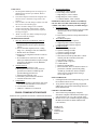
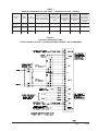
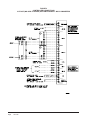
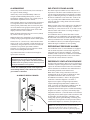
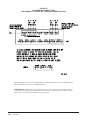
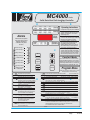
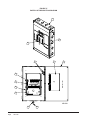
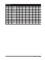
INSTALLATION INSTRUCTIONS
& REPLACEMENT PARTS LIST
MC4000 SERIES SOLID STATE
DUAL UNIT LEAD/LAG CONTROLLER
Bard Manufacturing Company, Inc.
Bryan, Ohio 43506
Since 1914...Moving ahead, just as planned.
Manual No.:
Supersedes:
File:
Date:
2100-563C
2100-563B
Vol. III Tab 19
06-25-12
Manual
Page
2100-563C
1 of 40
CONTENTS
Getting Other Information and Publications
3
MC4000 General Information
Shipping Damage .................................................. 4
General .................................................................. 4
Theory of Operation ............................................... 4
Controller Certifications ......................................... 4
Specifications/Features for Basic Controller
MC4000 Basic Controller ....................................... 5
Mounting the Controller
Installation Instructions .......................................... 5
Temperature Sensors
Two Optional Sensor Inputs ................................... 5
Temperature Sensor Logic
Using Multiple Sensors .......................................... 5
Controller Input/Output Specifications
MC4000 Controller Connections ............................ 6
Specifications/Features for Alarm Boards
MC4000-A with Optional Base Alarm ..................... 6
MC4000-B with Enhanced Version Alarm .............. 6
Low Voltage Field Wiring
Circuitry in the MC4000 ......................................... 7
Controller Grounding
Earth ground .......................................................... 7
Controller Power-Up
Time Delay on Power-Up ....................................... 7
Fire Suppression Circuit
Disabling the MC4000 ........................................... 7
Staging Delay Periods
Stages 1 - 4 ............................................................ 7
Blower Operation
Various Blower Options ......................................... 7
Advance (Swap) Lead/Lag Unit Feature
Manual Switching of Units ..................................... 7
Accelerate Timer Feature
Testing the Timer Function ..................................... 7
General Programming Overview
Buttons & Function ................................................ 8
Humidity Control Option
Adding Optional Humidity Control .......................... 9
Cooling Operating Sequences
for Alternating Lead/Lag/Lead/Lag Config ........ 9-11
Cooling Operating Sequences
for Non-Alt Lead/Lead/Lag/Lag Config ........... 11-13
Heating Sequence of Operation ........................... 13
Specifications Opt. Remote Comm. Board .... 14-15
CB4000 Communications Board ......................... 15
Controller Wiring
Refer to Connection Diagram .............................. 16
Security (Locking) Feature
Locking and Unlocking the MC4000 .................... 16
Generator Run Feature
Standby Generator Disable Operation ................. 16
Backup DC Power Connection
Input Connections Available ................................ 16
Alarm Wiring .......................................................... 31
2nd Stage Cooling Alarm ...................................... 31
Refrigerant Pressure Alarms ................................ 31
Emergency Ventilation Sequence ........................ 31
Programming Instructions ................................... 34
Manual 2100-563C
Page
2 of 40
Figures
Figure 1
Controller Connections 1-Stage (WA/WL, W**A/
W**L Series) A/C w/No Economizers ..... 17
Figure 2
Controller Connections 2-Stage (WA*S/WL*S
Series) A/C - No Economizers ................ 18
Figure 3
Controller Connections 1-Stage (WA/WL, W**A/
W**L Series) A/C - No Econo with Alarm Board &
CB4000 Comm. Board ........................... 19
Figure 4
Controller Connections 2-Stage (WA*S/WL*S
Series) A/C - No Econo with Alarm Board &
CB4000 Comm. Board ........................... 20
Figure 5
Controller Connections 1-Stage (WA/WL, W**A/
W**L Series) A/C-Older EIFM Econo ..... 21
Figure 6
Controller Connections 2-Stage (WA*S/WL*S
Series) A/C-Older Style EIFM Econo ...... 22
Figure 7
Controller Connections 1-Stage (WA/WL, W**A/
W**L Series) A/C w/Older Style EIFM Econo &
w/Alarm Board/CB4000 Comm. Board ... 23
Figure 8
Controller Connections 2-Stage (WA*S/WL*S
Series) A/C w/Older Style EIFM Econo & w/Alarm
Board/CB4000 Comm. Board ................. 24
Figure 9
Controller Connections 1-Stage (WA/WL, W**A/
W**L Series) A/C w/ECONWMT Econo .. 25
Figure 10 Controller Connections 2-Stage (WA*S/WL*S
Series) A/C w/ECONWMT Econo .......... 26
Figure 11 Controller Connections 1-Stage (WA/WL, W**A/
W**L Series) A/C w/ECONWMT Econo & w/Alarm
Board/CB4000 Comm. Board ................. 27
Figure 12 Controller Connections 2-Stage (WA*S/WL*S
Series) A/C w/ECONWMT Econo & w/Alarm
Board/CB4000 Comm. Board ................. 28
Figure 13 Controller Connections Heat Pumps No Economizers ..................................... 29
Figure 14 Controller Connections Heat Pumps No Economizers w/Opt. Alarm Board &
CB4000 Communication Board .............. 30
———
Alarm LED Display Board ...................... 31
Figure 15 Alarm Board Connections for Normally Closed
"NC" Open-On-Alarm Strategy ............... 32
Figure 16 Alarm Board Connections for Normally Open
"NO" Close-On-Alarm Strategy .............. 33
———
MC4000 Label ........................................ 35
Figure 17 Parts List Description Diagram ............... 36
Tables
Table 1
Hook-Up Diagram Selection ................... 17
Table
Parts List ................................................ 37
Getting Other Information and Publications
These publications can help you install the air
conditioner or heat pump. You can usually find these at
your local library or purchase them directly from the
publisher. Be sure to consult current edition of each
standard.
FOR MORE INFORMATION, CONTACT
THESE PUBLISHERS:
ACCA
Air Conditioning Contractors of America
1712 New Hampshire Avenue, NW
Washington, DC 20009
Telephone: (202) 483-9370
Fax: (202) 234-4721
ANSI
American National Standards Institute
11 West Street, 13th Floor
New York, NY 10036
Telephone: (212) 642-4900
Fax: (212) 302-1286
Standard for the Installation .............. ANSI/NFPA 90A
of Air Conditioning and
Ventilating Systems
Standard for Warm Air Heating ........ ANSI/NFPA 90B
and Air Conditioning Systems
ASHRAE American Society of Heating, Refrigerating,
and Air Conditioning Engineers, Inc.
1791 Tullie Circle, N.E.
Atlanta, GA 30329-2305
Telephone: (404) 636-8400
Fax: (404) 321-5478
BARD
Bard Manufacturing Company, Inc.
1914 Randolph Drive
Bryan, OH 43506
Telephone: (419) 636-1194
Fax: (419) 636-2640
Manual
Page
2100-563C
3 of 40
** IMPORTANT **
The equipment covered in this manual is to be installed by
trained, experienced service and installation technicians.
Please read entire manual before proceeding.
SHIPPING DAMAGE
Upon receipt of equipment, the carton should be checked
for external signs of shipping damage. If damage is
found, the receiving party must contact the last carrier
immediately, preferably in writing, requesting inspection
by the carrier’s agent.
GENERAL
These instructions explain the operation, installation and
troubleshooting of the MC4000 controller.
All internal wiring is complete. Only attach low voltage
field wiring to designated terminal strips.
The MC4000 is for use with units with or without
economizers, can be configured for use with heat pumps,
and has a dehumidification control feature if an optional
humidity controller is connected.
Each unit should be sized to handle the total load of the
structure if 100% redundancy is required.
It is recommended that a five (5) minute compressor
time delay relay be installed in each unit if not so
equipped.
The MC4000 controller is suitable for both 50 and 60
HZ operation, and is fully configurable such that it can
be used in virtually any installation. See Controller
Programmable Features and Default Settings.
THEORY OF OPERATION
The controller is used to control two wall mount air
conditioners from one control system. It provides total
redundancy for the structure and equal wear on both
units. It can be used with units with or without
economizers and it is recommended that both units be
equipped alike.
Manual 2100-563C
Page
4 of 40
The MC4000 controller can be configured for alternative
(lead/lag/lead/lag) sequence, which is default setting. It
can be changed to non-alternating (lead/lead/lag/lag)
sequence as required for special applications or user
preference.
The MC4000 can be equipped with one of two alarm
boards, and these can be factory-installed or installed at
any time in the field if so desired.
Should the base controller alone be initially installed, it
is easily upgradeable by simple snap-in, plug-in field
installation of either one of the alarm boards, requiring
only the connection of the building alarm circuitry to the
alarm boards. Form C dry contact alarm relays are used,
offering both NO and NC switching to meet the user’s
specific alarm protocol, providing complete flexibility to
meet any user's requirements. All alarm actuations are
individually indicated on the controller front panel.
There is an Ethernet based remote communication
option that can be either factory or field installed. See
section on Communication Module.
CONTROLLER CERTIFICATIONS
The MC4000 main controller board, optional alarm
boards, optional communication module, and remote
sensors have undergone extensive testing for immunity
and emissions. This system is FCC-compliant, in
accordance with CE requirements, and meets the
following standards:
MC4000 Series
Master Controller
This device complies with FCC Rule Part 15, Subpart B,
Class A. Operation is subject to the following two
conditions:
1. This device may not cause harmful interference
2. This device must accept any interference
received, including that which may cause
undesired operation.
This device complies with CE Standards EN55011/
EN50081 and EN55024 for ISM Equipment, Class A.
This ISM device also complies with Canadian ICES – 001.
Bard Manufacturing Company, Inc.
Bryan, OH 43506
SPECIFICATIONS/FEATURES FOR BASIC
CONTROLLER
MC4000 Basic Controller
•Input power: 18-32 VAC, 60/50Hz, power is supplied from
A/C #1 and/or A/C #2
•Isolation circuitry: no line or low voltage phasing required
•Backup power: connection for -24 VDC or -48 VDC (-20 to 56V) maintains microprocessor operation, front panel indication
& alarm relay operation during commercial power outages.
•Digital display: 4-character LCD
•Temperature display: F or C
•HVAC outputs: Form A (NO) relays (1A @ 24 VAC)
•Cooling control stages:
2 for each A/C unit (4 total) when configured for economizers
1 for each A/C unit (2 total) when configured for no economizers
•Heating Control stages:
1 for each A/C unit, 2 for each heat pump if so configured
•Dehumidification circuit: requires optional humidity
controller as input signal
•Operating temperature range: 0 to 120F (-18 to 49C)
•Storage temperature range: -20 to 140F (-29 to 60C)
•Temperature accuracy: +/- 1F from 60-85F (16-30C)
+/- 1% outside 60-85F
•Lead/lag changeover time: 0 to 30 days
•Timing accuracy: +/- 1%
•Inter-stage time delay: 10 seconds between stages
•Inter-stage differential:
Stage 1 to 2 - Range 2-6F, default is 4
Stage 2 to 3 - Range 2-3F, default is 2
Stage 3 to 4 - Range 2-3F, default is 2
•On-Off differential: 2F (1C) is standard, 4F (3C) when
“excessive cycling” mode is enabled
•Cooling set point range: 65 to 90F (18.3 to 32.2C)
•Comfort setting-Cooling 72F (22C), Heating 68F(20C), for 1 hour
•Dead band (difference between cooling and heating set
points): 2F to 40F (1.1C to 22.2C)
•Fire/smoke interface: standard NC circuit jumper, remove
for connection to building system control, shuts down both
A/C units immediately
•Memory: EEPROM for set point and changeable
parameters (maintains settings on power loss)
•Space temperature sensors: 1 local is standard, will accept up
to 2 optional 25' remote sensors, Bard part number 8612-023.
When multiple sensors are used, temperatures are averaged
•Controller Enclosure: 20-gauge pre-painted steel, 9.25"W x
13.50"H x 3.00"D, hinged cover, thirteen (13) .875" diameter
electrical knockouts
•LEDs for basic controller: Lead unit, Cooling stages 1
through 4, Heating Stages 1 – 4, Dehumidification operation
•Six (6) Push-button controls: On/Off switch-Change lead
unit-Increase & Decrease set points-Program/Save-Comfort.
MOUNTING THE CONTROLLER
Included in the controller carton is the controller and
installation instructions.
The controller should be installed on a vertical wall
approximately four (4) feet above the floor-away from drafts &
outside doors or windows. Four (4) mounting holes are provided
for mounting to the wall and 7/8" holes for conduit connections
are provided in both the base, sides & top of the controller.
TEMPERATURE SENSORS
The standard (local) temperature sensor has 12" leads and
comes installed from the factory.
A secondary sensor is located internally on the main
controller board and serves as a reference and back-up
sensor to the local sensor. Any differential of +/- 12F
between the on-board and local sensor will cause the
controller to use the local sensor as its point of reference.
If the differential is greater than 12F then the controller
will check to determine the on-board sensor is reading a
temperature that is between the SP (set-point) plus 12F
and the SP minus the DB (dead-band) minus 12F. If it is
the on-board sensor will become the valid sensor reading
and the controller will ignore the local sensor reading. If
it is not then the controller will still use the local sensor
reading. This is to add additional level of operational
capability in the rare event the local sensor fails. If the
controller is operating in this mode it is indicated by the
lower left decimal point flashing in the display. Note: for
purposes of testing when the local sensor is manually
driven higher or lower by applying warm or cool water to
the probe the on-board sensor is inhibited for the first
30-minutes following power up, or when power is cycled
off and back on.
The controller is designed to accept 1 or 2 additional
sensors and those have 25-foot leads. The Bard part
number for the optional sensor with 25-foot leads is
8612-023. These can be installed as required in the
structure to address hot spots, barriers to airflow, etc.
It is recommended that the sensor lead wires be installed
in conduit for protective purposes.
If alarm boards are utilized, the highest reading of any
connected sensor will be used for high temperature alarm
and the lowest reading sensor will be used for low
temperature alarm.
NOTE: All sensors are polarity sensitive. The copper
lead must connect to terminal CU, and the silver lead
to AG. Sensors are solid state, not RTD. Use only
sensors supplied by Bard. Sensor leads can be
extended up to 200 feet. Use 18-gauge twisted pair
with soldered connections.
TEMPERATURE SENSOR LOGIC
The standard local (LSEn) sensor monitors the
temperature at the controller location. If this is the only
sensor connected, it will control the temperature read-out,
the space (building) temperature, and also be used for Low
and High Temperature alarm functions.
If one or more REMOTE sensors are installed and
connected (Rem 1 or Rem 2), the temperature read-out
will display and the building will be controlled to an
average of all connected sensors. If there is more than
10F difference from the highest to the lowest connected
sensor, the actual control will be governed by the hottest
sensor for cooling and the coldest sensor for heating.
If multiple temperature sensors are used, the High and
Low temperature alarms will be governed by the average
of the connected sensors.
Manual
Page
2100-563C
5 of 40
BASIC MC4000 CONTROLLER
INPUT/OUTPUT SPECIFICATIONS
SPECIFICATIONS/FEATURES FOR
ALARM BOARDS
MC4000 CONTROLLER CONNECTIONS
MC4000-A w/Optional Base Alarm Board
(Inputs/Outputs)
Located on Main Controller Board
C – 24VAC common
R – 24VAC hot
G – fan (Form A, NO)
Y1 – 1st-stage cool (Form A, NO)
Y2 – 2nd-stage cool (Form A, NO)
W – heat (Form A, NO)
Unit #2
C – 24VAC common
R – 24VAC hot
G – fan (Form A, NO)
Y1 – 1st-stage cool (Form A, NO)
Y2 – 2nd-stage cool (Form A, NO)
W – heat (Form A, NO)
F1-F2 Fire/smoke interface
Shipped with jumper installed (a)
48Vdc Back-up power input
-24Vdc or –48Vdc
-20V to –56V range
NOTE:
Local
Main sensor, 12-inch leads
CU – copper, AG – silver
Sensors are
Polarity sensitive
solid state,
Rem 1 Optional remote indoor sensor
not RTD.
CU – copper, AG – silver
Use Bard
Polarity sensitive
sensors only.
Rem 2 Optional remote indoor sensor
CU – copper, AG – silver
Polarity sensitive
Gen
Generator interface G1-G2
Shipped with jumper installed (a)
H1-H2 Humidity controller input
Requires optional controller
Field installed
(a) These connections require either jumper or Normally
Closed (NC) relay contact at the Fire/Smoke and Generator
interface for Controller to function.
Unit #1
Note: All alarm and output relays are dry contacts rated
1A @ 24 VAC.
Note: All alarm relay outputs have 10-second delay
before issuing to protect against nuisance alarm signals.
NOTE: If this alarm board was not originally factory
installed, it can be field-installed at anytime. Bard
part number is AB3000-A.
Inputs
Lockout 1
Lockout 2
Outputs
Smoke/Fire
Lockout 1
Lockout 2
Power Loss 1
Power Loss 2
Low Temp
High Temp 1
2,3 – input from HVAC #1
2, 3 – input from HVAC #2
Form C (SPDT)
Form C (SPDT)
Refrigerant alarm HVAC #1
Form C (SPDT)
Refrigerant alarm HVAC #2
Form C (SPDT)
Power loss HVAC #1
Form C (SPDT)
Power loss HVAC #2
Form C (SPDT)
Low temperature alarm
Form C (SPDT)
High temperature alarm #1
MC4000-B w/Enhanced Version Alarm Board
(Additional Outputs) plus MC4000-A Inputs/Outputs
NOTE: If this alarm board was not originally factory
installed, it can be field-installed at anytime. Bard
part number is AB3000-B.
High Temp 2
Form C (SPDT)
High temperature alarm #2
Controller
Form C (SPDT)
Controller failure alarm
Econ 1
E, F - Form A (NO)
See note (b)
Econ 2
E, F - Form A (NO)
See note (b)
2nd Stage (c)
Form C (SPDT)
2nd-stage cooling alarm
(b) Make these connections to terminals E & F in HVAC 1
and 2 respectively if desired to have economizers open for
emergency ventilation at High Temp Alarm #2 setpoint
condition.
(c) For units with 2-stage compressors, 2nd stage cooling
alarm activates on cooling Stage 3 initiation.
Alarm relays can be wired for NO (close on alarm) or NC (open on alarm) strategy. Alarm relays can be used individually if
there are enough available building alarm points, or can be arranged into smaller groups or even a single group so that all
alarm capabilities can be utilized. When multiple alarms are grouped together and issued as a single alarm there will be no
off-site indication of which specific problem may have occurred, only that one of the alarms in the group has been triggered.
The individual alarm problem will be displayed on the LED display on face of the controller.
Manual 2100-563C
Page
6 of 40
LOW VOLTAGE FIELD WIRING
The MC4000 is powered from the air conditioners that it
is controlling, 24 VAC (18-32V) low voltage only.
Circuitry in the MC4000 isolates the power supplies of
the two air conditioners so that no back feeds or phasing
problems can occur. Additionally, if one air conditioner
loses power, the MC4000 and the other air conditioner
are unaffected and will continue to operate normally.
Connect the low voltage field wiring from each unit per the
low voltage field wiring diagrams in Section on “Controller
Wiring”. NOTE: Maximum of 18-gauge control wiring
should be used. Using heavier gauge wiring can create
excessive stress on the control board as door is opened and
closed. Create a wiring loop so the door can open and
close without stressing terminal blocks.
CONTROLLER GROUNDING
A reliable earth ground must be connected in addition to
any grounding from conduit. Grounding lugs are
supplied for this purpose.
CONTROLLER POWER-UP
Whenever power is first applied to the controller, there is
a twenty (20) second time-delay prior to any function
(other than display) becoming active. This time-delay is
in effect if the controller On/Off button is used when
24VAC from air conditioners is present, and also if
controller is in “ON” position and 24VAC from air
conditioners is removed and then restored.
FIRE SUPPRESSION CIRCUIT
To disable the MC4000 and shut down both air
conditioners, terminals F1 and F2 may be used. The F1
and F2 terminals must be jumpered together for normal
operation. A normally closed (nc) set of dry contacts
may be connected across the terminals and the factory
jumper removed for use with a field-installed fire
suppression system. The contacts must open if a fire is
detected. See appropriate connection diagram - Figures
1, 2 or 3 for this connection. Contacts should be rated
for pilot duty operation at 2 amp 24VAC minimum.
Shielded wire (22-gauge minimum) must be used, and
the shield must be grounded to the controller enclosure.
IMPORTANT NOTE: Older Bard R-22 models employ
an electronic blower control that has a 60-second
blower off-delay. Current production R-410A models do
not use a blower off-delay device and the remainder of
this (paragraph) does not apply. In order to have
immediate shutdown of the blower motor, in addition to
disabling the run function of the air conditioners will
require a simple wiring modification at the blower
control located in the electrical control panel of the air
conditioners being controlled by the lead/lag controller.
To eliminate the 60-second blower off-delay, disconnect
and isolate the wire that is factory-connected to the “R”
terminal on the electronic blower control, and then
connect a jumper from the “G” terminal on the blower
control to the “R” terminal on the blower control. The
electronic blower control will now function as an on-off
relay with no off-delay, and the blower motor will stop
running immediately when the F1-F2 fire suppression
circuit is activated (opened).
STAGING DELAY PERIODS
The following delays are built in for both cooling & heating:
Stage 1 – 0 seconds for blower (if not already on as
continuous)
10 seconds for cooling or heating output
Stage 2 – 10 seconds after Stage 1 for blower
10 additional seconds for cooling or heating
output
Stage 3 – 10 seconds after Stage 2
Stage 4 – 10 seconds after Stage 3
Note: For cooling Stages 1 and 2, the stage LED will
blink for 10 seconds while the cooling output is delayed
after that stage is called for. There is also a delay after
the stage is satisfied, and after the LED stops blinking,
the stage will turn off. There is a minimum 10-second
delay between stages 2 & 3, and 3 & 4, but no delayed
output when stage is turned on or off, and LED for those
stages will not blink.
BLOWER OPERATION
The controller can be configured to have main HVAC
blowers cycle on and off on demand; have all blowers
run continuously; or have the lead unit blower run
continuously with the lag unit blower cycling on
demand. Default setting is the blower(s) start and stop
on demand. There is also an option to have all blowers
cycle on if one remote sensor is connected, and a
temperature difference of more than 5F between any two
sensors is observed. This helps to redistribute the heat
load within the structure and should reduce compressor
operating time.
When any of the stages are satisfied, the stage LED will
blink for ten (10) seconds before the stage is actually
turned off.
ADVANCE (SWAP) LEAD/LAG UNIT
FEATURE
Pressing the Advance button for one (1) second will cause
the lead and lag units to change positions. This may be
useful during service and maintenance procedures.
ACCELERATE TIMER FEATURE
Pressing the UP arrow button for five (5) seconds will
activate an accelerate (speed-up) mode, causing the
normal changeover time increments of days to be
reduced to seconds. Example: 7 days becomes 7
seconds. When “ACC” displays, release button.
Whichever LED is on, indicating lead unit will blink
over for each second until the controller switches. This
is a check for the timer functionality.
Manual
Page
2100-563C
7 of 40
GENERAL PROGRAMMING OVERVIEW
MC4000 CONTROLLER BUTTONS AND FUNCTION
On/Off Button
1.
2.
Press and release the On/Off button to turn On controller, 4-character display will illuminate and Lead unit LED will light.
Press and release the On/Off button to turn Off controller. Controller will go dark and A/C units will stop.
Comfort Button
1.
2.
3.
4.
Press and release the Comfort button to change the Cooling Set Point to 72F and the Heating Set Point to 68F for a period of 1 hour.
Set Points will return to the programmed settings automatically after 1 hour.
Pressing the Comfort button during the 1 hour period will deactivate the Set Point change.
The temperature display will flash the current temperature while in override mode.
Program Button
1.
2.
Press the Program button and release it when the message “Prog” appears on the display.
Refer to Programming Instructions and follow these commands to change from Default settings.
Advance/Change/Save Button
1.
2.
3.
Press and release the Advance button to swap lead and lag unit positions.
When in Program mode the Down and Up buttons are used to scroll through the programming steps.
A flashing display means that the particular function of that programming step is “set”, and the display will alternate between the step function and
the setting.
To change the setting press the Change button and the display will stop flashing, allowing change to the setting.
Use Down or Up arrows to change setting as desired, and press the Save button and proceed as desired.
When done with programming changes press the Program button until display stops flashing and room temperature is shown.
4.
5.
6.
Up and Down Buttons
These buttons are used to change the settings in conjunction with the Advance/Change/Save button when in programming mode.
CONTROLLER PROGRAMMABLE FEATURES AND DEFAULT SETTINGS
Order /
Display
LS E n
Description
Temperature at local (main) sensor
—
—
77F (25C)
Deadband between cooling SP and heating set point
2 to 40F (1 to 24C)
17F (9.4C)
Temperature at remote sensor 1 location, if connected
—
—
Temperature at remote sensor 2 location, if connected
—
—
None, Lead, Both
None
F or C
F
Yes or No
Yes
Cooling set point temperature
db
r1
r2
Continuous blower operation
deg
Controller system operates in F or C
Alt
Alternating Lead-Lag-Lead-Lag sequence or Non-Alternating Lead-Lead-Lag-Lag sequence —
Yes = Alternating
LLC O
Default
65 to 90F (18 to 32C)
SP
cFAn
Range / Choice
1 - 30 days, or 0 for disabled
7
Heat pump logi c enabled — only for 1-stage heat pumps and forces Lead-Lag sequence
(overrides a Non-Alt setting)
Yes or No
No
C bd5
Unit 1 and 2 blowers automatically both run if delta T >5F between any 2 connected sensors
Yes or No
Yes
OFde
3-minute lead unit & 4-minute lag unit off-delay enabled
Yes or No
No
crun
Minimum 3-minute compressor runtime enabled
Yes or No
No
LoA L
Low temperature alarm setpoint
28 to 65F (-2 to 18C)
45F (7.2C)
HAL1
High temperature alarm level #1 setpoint
70F to 120F (21 to 49C)
90F (32C)
HAL2
High temperature alarm level #2 setpoint
70F to 120F (21 to 49C)
95F (35C)
Controller is locked and no changes can be made. Consult building authority.
If locked, display will show
Locd if changes attempted
Unlocked
HP
L o cd
Lead-Lag changeover time (Days)
I nter-Stage Differential
ISd2
From Stage 1 to Stage 2
2, 3, 4, 5 or 6F
4
ISd3
From Stage 2 to Stage 3
2 or 3F
2
ISd4
From Stage 3 to Stage 4
2 or 3F
2
On/Off Differential (Hysterisis)
C S on
Turn "On" above SP for Stage 1 Cooling
+1 or 2F
2
C S oF
Turn "Off" below SP for Stage 1 Cooling
-1, 2, 3 or 4F
-2
-1/+1 or -2/+2
-2/+2
1 or 2
1
Stage 2, 3 and 4 Cooling automatically set same as Stage 1 decisions
HSoo
All Heating Stages are equal -/+ on & off differential
C oP r
1 or 2-stage compressor, if set to 1 the 2nd stage Cooling Alarm activates on Cooling Call 2,
if set to 2 the 2nd stage Cooling Alarm activates on Cooling Call 3
Manual 2100-563C
Page
8 of 40
HUMIDITY CONTROL OPTION
Note: This function is not available if controller is
configured for heat pump.
The standard air conditioning system can be adapted to
perform dehumidification control by addition of a
simple humidity controller that closes-on-rise, and is
connected to terminals H1 and H2 on the main controller
board. Recommended Bard Part #8403-038 (H600A
1014). Both HVAC units must be equipped with electric
heat for this sequence to work properly. See appropriate
connection diagram - Figures 1 - 12 for this connection:
1. Temperature control always has priority over
dehumidification. If there is any stage of cooling
demand active, the dehumidification sequence is
locked out.
2. If all stages of cooling are satisfied, and relative
humidity is above the set point of humidity
controller:
a. The green “Dehumid. Operation” light will come
on, and the lag unit compressor and blower will
operate until the set point of humidity controller
is satisfied (or cancelled by a call for cooling).
b. If the space temperature drops to 67F, the electric
heater of the lead unit will cycle to help maintain
building temperature. It will cycle off at 69F.
c. If space temperature drops to 64F, the Stage 2
Heating light will come on and the lag unit
compressor operating for dehumidification mode
will cycle off until the building temperature rises
above 65F from 1st stage heat and building load.
The green “Dehumid. Operation” light stays on
during this sequence, and when Stage 2 Heating
light is Off, the compressor is On. The electric
heater in lag unit is locked out in
dehumidification mode.
Lag unit outputs G, Y1 and Y2 are all switched on
during dehumidification sequence. This is true for both
alternating and non-alternating controller configurations.
COOLING OPERATING SEQUENCES FOR
ALTERNATING LEAD/LAG/LEAD/LAG
CONFIGURATION
1.
1-Stage Compressor Units No Economizer
1st stage cooling set point is the setting (SP) input into
the controller. Factory default is 77F (25C). On a call for
cooling the blower of the lead unit will come on
immediately (if not already on – See Blower Operation),
and the Stage 1 LED will blink for 10-seconds before
going solid, at which time the compressor will start.
2nd cooling set point is 4F (default setting, user
selectable 2-6F) warmer than Stage 1. On a call for 2nd
Stage cooling the blower of the lag unit is turned on (if
not already on – See Blower Operation), and the Stage 2
LED will blink for 10-seconds before going solid, at
which time the compressor will start.
3rd and 4th stages are functional outputs but there is
nothing to be controlled.
2.
2-Stage Compressor Units No Economizer
st
1 stage cooling set point is the setting (SP) input into the
controller. Factory default is 77F (25C). On a call for
cooling the blower of the lead unit will come on
immediately (if not already on – See Blower Operation),
and the Stage 1 LED will blink for 10-seconds before
going solid, at which time the lead unit compressor will
start in compressor Stage 1 partial capacity operation.
2nd cooling set point is 4F (default setting, user selectable
2-6F) warmer than Stage 1. On a call for 2nd Stage
cooling the blower of the lag unit is turned on (if not
already on – See Blower Operation), and the Stage 2
LED will blink for 10-seconds before going solid, at
which time the lag unit compressor will start in
compressor Stage 1 partial capacity operation.
3rd cooling set point is 2F (default setting, user selectable
2-3F) warmer than Stage 2. On a call for 3rd Stage
cooling the Stage 3 LED comes on solid (no delay), and
the lead unit compressor will switch to compressor Stage
2 full capacity operation.
CAUTION
Humidity controller set point should be in 50-60%
relative humidity area: Setting controller to lower
settings will result in excessive operating time and
operating costs for the electric reheat, and in
extreme cases could cause evaporator (indoor) coil
freeze-up if there are periods of light internal
equipment (heat) loading.
Manual
Page
2100-563C
9 of 40
4th cooling set point is 2F (default setting, user selectable
2-3F) warmer than Stage 3. On a call for 4th Stage
cooling the Stage 4 LED comes on solid (no delay), and
the lag unit compressor will switch to compressor Stage 2
full capacity operation.
3.
1-Stage Compressor Units with Older EIFM
Economizers (Enthalpy OD Sensor)
1st stage cooling set point is the setting (SP) input into
the controller. Factory default is 77F (25C). On a call for
cooling the blower of the lead unit will come on
immediately (if not already on – See Blower Operation),
and the Stage 1 LED will blink for 10-seconds before
going solid, at which time the lead unit Y1 cooling
output turns on. If the outdoor temperature and humidity
conditions are below the set point of the economizer
control the lead unit economizer will operate instead of
the compressor. If outdoor conditions are not acceptable
for free cooling the compressor will automatically
operate instead of the economizer.
2nd cooling set point is 4F (default setting, user selectable
2-6F) warmer than Stage 1. On a call for 2nd Stage
cooling the blower of the lag unit is turned on (if not
already on – See Blower Operation), and the Stage 2
LED will blink for 10-seconds before going solid, at
which time the lag unit Y1 cooling output turns on. If the
outdoor temperature and humidity conditions are below
the set point of the economizer control the lag unit
economizer will operate instead of the compressor. If
outdoor conditions are not acceptable for free cooling
the compressor will automatically operate instead of the
economizer.
3rd cooling set point is 2F (default setting, user selectable
2-3F) warmer than Stage 2. On a call for 3rd Stage
cooling the lead unit economizer will close and the
compressor will operate.
4th cooling set point is 2F (default setting, user selectable
2-3F) warmer than Stage 3. On a call for 4th Stage
cooling the lag unit economizer will close and the
compressor will operate.
4.
1-Stage Compressor Units with Newer
ECONWMT Economizers (See Note A)
1st stage cooling set point is the setting (SP) input into
the controller. Factory default is 77F (25C). On a call for
cooling the blower of the lead unit will come on
immediately (if not already on – See Blower Operation),
and the Stage 1 LED will blink for 10-seconds before
going solid, at which time the lead unit Y1 cooling
output turns on. If the outdoor temperature and humidity
conditions are below the set point of the economizer
control the lead unit economizer will operate instead of
the compressor. If outdoor conditions are not acceptable
for free cooling the compressor will automatically
operate instead of the economizer.
Manual 2100-563C
Page
10 of 40
2nd cooling set point is 4F (default setting, user selectable 26F) warmer than Stage 1. On a call for 2nd Stage cooling the
blower of the lag unit is turned on (if not already on – See
Blower Operation), and the Stage 2 LED will blink for 10seconds before going solid, at which time the lag unit Y1
cooling output turns on. If the outdoor temperature and
humidity conditions are below the set point of the
economizer control the lag unit economizer will operate
instead of the compressor. If outdoor conditions are not
acceptable for free cooling the compressor will
automatically operate instead of the economizer.
3rd cooling set point is 2F (default setting, user selectable
2-3F) warmer than Stage 2. On a call for 3rd Stage
cooling the lead unit economizer will continue to
operate as long as outdoor conditions are acceptable, and
the compressor will operate.
4th cooling set point is 2F (default setting, user selectable
2-3F) warmer than Stage 3. On a call for 4th Stage
cooling the lag unit economizer will continue to operate
as long as outdoor conditions are acceptable, and the
compressor will operate.
5.
2-Stage Compressor Units with Older EIFM
Economizers
1st stage cooling set point is the setting (SP) input into the
controller. Factory default is 77F (25C). On a call for
cooling the blower of the lead unit will come on
immediately (if not already on – See Blower Operation),
and the Stage 1 LED will blink for 10-seconds before going
solid, at which time the lead unit Y1 cooling output turns
on. If the outdoor temperature and humidity conditions are
below the set point of the economizer control the lead unit
economizer will operate instead of the compressor. If
outdoor conditions are not acceptable for free cooling the
compressor will automatically operate on compressor Stage
1 partial capacity instead of the economizer.
2nd cooling set point is 4F (default setting, user selectable
2-6F) warmer than Stage 1. On a call for 2nd Stage cooling
the blower of the lag unit is turned on (if not already on –
See Blower Operation), and the Stage 2 LED will blink
for 10-seconds before going solid, at which time the lag
unit Y1 cooling output turns on. If the outdoor
temperature and humidity conditions are below the set
point of the economizer control the lag unit economizer
will operate instead of the compressor. If outdoor
conditions are not acceptable for free cooling the
compressor will automatically operate on compressor
Stage 1 partial capacity instead of the economizer.
3rd cooling set point is 2F (default setting, user selectable
2-3F) warmer than Stage 2. On a call for 3rd Stage cooling
the lead unit economizer will close and the compressor
will operate on full capacity compressor Stage 2.
4th cooling set point is 2F (default setting, user selectable 23F) warmer than Stage 3. On a call for 4th Stage cooling
the lag unit economizer will close and the compressor will
operate on full capacity compressor Stage 2.
6.
2-Stage Compressor Units with Newer
ECONWMT Economizers (See Note A)
1st stage cooling set point is the setting (SP) input into
the controller. Factory default is 77F (25C). On a call
for cooling the blower of the lead unit will come on
immediately (if not already on – See Blower
Operation), and the Stage 1 LED will blink for 10seconds before going solid, at which time the lead unit
Y1 cooling output turns on. If the outdoor temperature
and humidity conditions are below the set point of the
economizer control the lead unit economizer will
operate instead of the compressor. If outdoor conditions
are not acceptable for free cooling the compressor will
automatically operate on compressor Stage 1 partial
capacity instead of the economizer.
2nd cooling set point is 4F (default setting, user
selectable 2-6F) warmer than Stage 1. On a call for 2nd
Stage cooling the blower of the lag unit is turned on (if
not already on – See Blower Operation), and the Stage 2
LED will blink for 10-seconds before going solid, at
which time the lag unit Y1 cooling output turns on. If
the outdoor temperature and humidity conditions are
below the set point of the economizer control the lag
unit economizer will operate instead of the compressor.
If outdoor conditions are not acceptable for free cooling
the compressor will automatically operate on
compressor Stage 1 partial capacity instead of the
economizer.
3rd cooling set point is 2F (default setting, user
selectable 2-3F) warmer than Stage 2. On a call for 3rd
Stage cooling the lead unit economizer will continue to
operate as long as outdoor conditions are acceptable,
and the compressor will operate on compressor Stage 1
partial capacity. If outdoor conditions are not acceptable
for free cooling the lead unit compressor will
automatically be operating on compressor Stage 1
partial capacity and will go to Stage 2 full capacity
operation.
4th cooling set point is 2F (default setting, user
selectable 2-3F) warmer than Stage 3. On a call for 4th
Stage cooling the lag unit economizer will continue to
operate as long as outdoor conditions are acceptable,
and the compressor will operate on compressor Stage 1
partial capacity. If outdoor conditions are not
acceptable for free cooling the lag unit compressor will
automatically be operating on compressor Stage 1
partial capacity and will go to Stage 2 full capacity
operation.
COOLING OPERATING SEQUENCES FOR
NON-ALTERNATING LEAD/LEAD/LAG/
LAG CONFIGURATION
Note: Heat pumps cannot be operated in Non-Alternating
Lead/Lead/Lag/Lag sequence. Selecting Heat Pump =
Yes will override a Non-Alternating selection and force
system to Alternating Lead/Lag/Lead/Lag sequence.
1.
2-Stage Compressor Units No Economizer
1st stage1st stage cooling set point is the setting (SP)
input into the controller. Factory default is 77F (25C).
On a call for cooling the blower of the lead unit will
come on immediately (if not already on – See Blower
Operation), and the Stage 1 LED will blink for 10seconds before going solid, at which time the lead unit
compressor will start in compressor Stage 1 partial
capacity operation.
2nd cooling set point is 4F (default setting, user
selectable 2-6F) warmer than Stage 1, at which time the
lead unit compressor will switch to compressor Stage 2
full capacity.
3rd cooling set point is 2F (default setting, user selectable
2-3F) warmer than Stage 2. On a call for 3rd Stage
cooling the blower of the lag unit will come on
immediately (if not already on – See Blower Operation),
and Stage 3 LED will blink for 10-seconds before going
solid, and then the lag unit compressor will start in
compressor Stage 1 partial capacity.
4th cooling set point is 2F (default setting, user selectable
2-3F) warmer than Stage 3. On a call for 4th Stage
cooling the Stage 4 LED comes on solid (no delay), and
the lag unit compressor will switch to compressor Stage
2 full capacity operation.
2.
1-Stage Compressor Units with Older EIFM
Economizers
1st stage cooling set point is the setting (SP) input into
the controller. Factory default is 77F (25C). On a call for
cooling the blower of the lead unit will come on
immediately (if not already on – See Blower Operation),
and the Stage 1 LED will blink for 10-seconds before
going solid, at which time the lead unit Y1 cooling
output turns on. If the outdoor temperature and humidity
conditions are below the set point of the economizer
control the lead unit economizer will operate instead of
the compressor. If outdoor conditions are not acceptable
for free cooling the compressor will automatically
operate instead of the economizer.
2nd cooling set point is 4F (default setting, user
selectable 2-6F) warmer than Stage 1. On a call for 2nd
Stage cooling the lead unit Y2 cooling output turns on.
The lead unit economizer will close and the compressor
will operate. If the compressor is already running from
1st stage cooling call due to outdoor conditions being
outside of free cooling range no action occurs at 2nd
stage set point.
Manual
Page
2100-563C
11 of 40
3rd cooling set point is 2F (default setting, user selectable
2-3F) warmer than Stage 2. On a call for 3rd Stage
cooling the blower of the lag unit is turned on (if not
already on – See Blower Operation), and the Stage 3
LED will blink for 10-seconds before going solid, and
the lag unit economizer will operate if the outdoor
temperature and humidity conditions are below the set
point of the economizer control. If outdoor conditions
are not acceptable for free cooling the compressor will
automatically operate instead of the economizer.
4th cooling set point is 2F (default setting, user selectable
2-3F) warmer than Stage 3. On a call for 4th Stage
cooling the lag unit economizer will close and the
compressor will operate. If the compressor is already
running from 3rd stage cooling call due to outdoor
conditions being outside of free cooling range no action
occurs at 2nd stage set point.
3.
1-Stage Compressor Units with Newer
ECONWMT Economizers (See Note A)
1st stage cooling set point is the setting (SP) input into
the controller. Factory default is 77F (25C). On a call for
cooling the blower of the lead unit will come on
immediately (if not already on – See Blower Operation),
and the Stage 1 LED will blink for 10-seconds before
going solid, at which time the lead unit Y1 cooling
output turns on. If the outdoor temperature and humidity
conditions are below the set point of the economizer
control the lead unit economizer will operate instead of
the compressor. If outdoor conditions are not acceptable
for free cooling the compressor will automatically
operate instead of the economizer.
2nd cooling set point is 4F (default setting, user
selectable 2-6F) warmer than Stage 1. On a call for 2nd
stage cooling the lead unit Y2 cooling output turns on. If
the outdoor temperature and humidity conditions are
below the set point of the economizer control the lead
unit economizer will continue to operate, and the
compressor will operate. If the compressor is already
operating on 1st stage cooling because outside free
cooling range no action occurs at 2nd cooling set point.
3rd cooling set point is 2F (default setting, user selectable
2-3F) warmer than Stage 2. On a call for 3rd Stage
cooling the blower of the lag unit will come on
immediately (if not already on – See Blower Operation),
and the Stage 3 LED will blink for 10-seconds before
going solid, at which time the lag unit Y1 cooling output
turns on. The lag unit economizer will operate if the
outdoor temperature and humidity conditions are below
the set point of the economizer control. If outdoor
conditions are not acceptable for free cooling the
compressor will automatically operate instead of the
economizer.
Manual 2100-563C
Page
12 of 40
4th cooling set point is 2F (default setting, user selectable
2-3F) warmer than Stage 3. On a call for 4th Stage
cooling the lag unit Y2 cooling output turns on
activating the lag unit compressor. If the outdoor
temperature and humidity conditions are below the set
point of the economizer control the lag unit economizer
will continue to operate. If the compressor is already
operating on 3rd stage cooling because outside free
cooling range no action occurs at 4th cooling set point.
4.
2-Stage Compressor Units with Older EIFM
Economizers
1st stage cooling set point is the setting (SP) input into
the controller. Factory default is 77F (25C). On a call for
cooling the blower of the lead unit will come on
immediately (if not already on – See Blower Operation),
and the Stage 1 LED will blink for 10-seconds before
going solid, at which time the lead unit Y1 cooling
output turns on. If the outdoor temperature and humidity
conditions are below the set point of the economizer
control the lead unit economizer will operate instead of
the compressor. If outdoor conditions are not acceptable
for free cooling the compressor will automatically
operate on compressor Stage 1 partial capacity instead of
the economizer.
2nd cooling set point is 4F (default setting, user
selectable 2-6F) warmer than Stage 1. On a call for 2nd
stage cooling the lead unit Y2 cooling output turns on, at
which time the lead unit compressor will operate on
compressor Stage 2 full capacity. If the compressor is
already operating on Stage 1 partial capacity because
outside free cooling range the compressor will switch to
compressor Stage 2 full capacity.
3rd cooling set point is 2F (default setting, user selectable
2-3F) warmer than Stage 2. On a call for 3rd Stage
cooling the blower of the lag unit will come on
immediately (if not already on – See Blower Operation),
and the Stage 3 LED will blink for 10-seconds before
going solid. The lag unit economizer will operate if the
outdoor temperature and humidity conditions are below
the set point of the economizer control. If outdoor
conditions are not acceptable for free cooling the
compressor will automatically operate on compressor
Stage 1 partial capacity instead of the economizer.
4th cooling set point is 2F (default setting, user selectable
2-3F) warmer than Stage 3. On a call for 4th Stage
cooling the lag unit Y2 cooling output turns on, at which
time the lag unit compressor will operate on compressor
Stage 2 full capacity. If the compressor is already
operating on Stage 1 partial capacity because outside
free cooling range the compressor will switch to
compressor Stage 2 full capacity.
5.
2-Stage Compressor Units with Newer
ECONWMT Economizers (See Note A)
1st stage cooling set point is the setting (SP) input into
the controller. Factory default is 77F (25C). On a call for
cooling the blower of the lead unit will come on
immediately (if not already on – See Blower Operation),
and the Stage 1 LED will blink for 10-seconds before
going solid, at which time the lead unit Y1 cooling
output turns on. If the outdoor temperature and humidity
conditions are below the set point of the economizer
control the lead unit economizer will operate instead of
the compressor. If outdoor conditions are not acceptable
for free cooling the compressor will automatically
operate on compressor Stage 1 partial capacity instead of
the economizer.
2nd cooling set point is 4F (default setting, user
selectable 2-6F) warmer than Stage 1. On a call for 2nd
stage cooling the lead unit Y2 cooling output turns on. If
the outdoor temperature and humidity conditions are
below the set point of the economizer control the lead
unit economizer will continue to operate, and the
compressor will operate on compressor Stage 1 partial
capacity. If the compressor is already operating on
Stage 1 partial capacity because outside free cooling
range the compressor will switch to compressor Stage 2
full capacity.
3rd cooling set point is 2F (default setting, user selectable
2-3F) warmer than Stage 2. On a call for 3rd Stage
cooling the blower of the lag unit will come on
immediately (if not already on – See Blower Operation),
and the Stage 3 LED will blink for 10-seconds before
going solid, at which time the lag unit Y1 cooling output
turns on. The lag unit economizer will operate if the
outdoor temperature and humidity conditions are below
the set point of the economizer control. If outdoor
conditions are not acceptable for free cooling the
compressor will automatically operate on compressor
Stage 1 partial capacity instead of the economizer.
4th cooling set point is 2F (default setting, user selectable
2-3F) warmer than Stage 3. On a call for 4th Stage
cooling the lag unit Y2 cooling output turns on
activating the compressor. If the outdoor temperature
and humidity conditions are below the set point of the
economizer control the lag unit economizer will
continue to operate, and the compressor will operate on
compressor Stage 2 full capacity. If the compressor is
already operating on Stage 1 partial capacity because
outside free cooling range the compressor will switch to
compressor Stage 2 full capacity.
HEATING SEQUENCE OF OPERATION
Note: All heating sequences for air conditioners with
electric heat or heat pumps will automatically operate in
Alternating Lead/Lag/Lead/Lag sequence even if
controller is set to Non-Alternating for cooling with or
without economizers.
1.
Air Conditioners with Electric Heat
st
1 stage heating set point is the dead-band (db) below
the 1st stage cooling set point (the SP entered into the
program). The dead-band is adjustable from 2-40F, and
factory default is 17F.
2nd stage heating set point will operate at same interstage differential as set for cooling mode.
2.
Heat Pumps with Electric Heat
When the MC4000 controller is configured for heat
pump installations the 2nd-stage (Y2) outputs for both
units 1 and 2 are redefined and used to control the
reversing valves, and which are energized in heating
mode.
1st stage heating set point is the dead-band (db) below
the 1st stage cooling set point (the SP entered into the
program). The dead-band is adjustable from 2-40F, and
factory default is 17F.
1st-stage heating consists of lead unit blower coming on
(if not already on – See Blower Operation), and
reversing valve being energized. The Stage 1 heating
LED will blink for 10-seconds, at which time the
compressor turns on.
2nd heating set point is 4F (default setting, user selectable
2-6F) cooler than Stage 1. On a call for 2nd Stage heating
the blower of the lag unit is turned on (if not already on
– See Blower Operation), the reversing valve is
energized, and the Stage 2 LED will blink for 10seconds before going solid, at which time the
compressor will start.
3rd-stage heating will be the electric heater, if so
equipped, in the lead unit. Stage 3 heating LED comes
on solid with no blinking.
4th-stage heating will be the electric heater, if so
equipped, in the lag unit. Stage 4 heating LED comes on
solid with no blinking.
Note A: Economizers in ECONWMT-Series are available
with either “T” temperature only outdoor sensor or “E”
enthalpy (temperature and humidity) outdoor sensor. The
“T” versions will have a fixed (but selectable) outdoor
temperature decision whereas on the “E” versions the
outdoor temperature decision will float based on outdoor
humidity and the selected Enthalpy curve in the
economizer control module.
Manual
Page
2100-563C
13 of 40
SPECIFICATIONS FOR OPTIONAL
REMOTE COMMUNICATION BOARD
CB4000 COMMUNICATION BOARD
Note: If this communication board was not originally
factory installed it can be field-installed at anytime. Bard
part number is CB4000. Either the –A or –B alarm board
is required for CB4000 to operate properly. It allows
remote access via Ethernet, depending upon level of
authority assigned, to all functions of the controller
system the same as it one was in the building where the
controller system is physically installed.
Required Input Connections to the CB4000 (these are
all internal connections from either the alarm board or
main controller board):
1.
2.
3.
4.
Fire/smoke connection from MC4000 main
controller board.
Refrigerant lockout inputs.
If economizers are used an additional 24V signal
wire is required from each air conditioner to the
controller system.
Communication cable from CB4000 plugs into phone
jack connection on main MC4000 controller board.
OPERATING SYSTEM
No special software is required to access the system. The
CB4000 has a default address, simply follow these
instructions:
TO ACCESS THE SYSTEM
1.
2.
Connect CAT 5 or CAT 6 Ethernet cable from
computer to Ethernet port on the CB4000.
Change your computer’s IP address as shown
below to gain initial access to the CB4000.
NOTE 1: Record your computer’s current IP settings
BEFORE making any changes. You will need to reset
back to these original settings once you’ve assigned an
IP address to the CB4000.
For XP or Windows 2000:
1.
2.
3.
4.
5.
6.
7.
8.
Open Control Panel, double click Network
Connections.
Double click Local Area Connection on the
General tab and select Properties.
Using the General tab, scroll to Internet
Protocol (TCP/IP).
Highlight Internet Protocol (TCP/IP) and select
Properties.
Change the addresses as follows:
IP address:
192.168.1.50
Subnet mask:
255.255.255.0
Default gateway:
192.168.1.1
Preferred DNS server:
192.168.1.10
Alternate DNS server:
192.168.1.11
Click OK and close all windows.
Start your browser, enter the CB4000’s default IP
address 192.168.1.67 and hit Enter.
The MC4000 log-in page should appear.
Manual 2100-563C
Page
14 of 40
For Vista or Windows 7:
1.
2.
3.
4.
5.
6.
7.
8.
9.
Open Control Panel, click Network & Internet.
Click Network & Sharing Center.
Click Local Area Network link.
Click Properties.
Highlight Internet Protocol Version 4 (TCP/
IPV4) and select Properties.
Change the addresses as follows:
IP address:
192.168.1.50
Subnet mask:
255.255.255.0
Default gateway:
192.168.1.1
Preferred DNS server:
192.168.1.10
Alternate DNS server:
192.168.1.11
Click OK and close all windows.
Start your browser, enter the CB4000’s default IP
address 192.168.1.67 and hit Enter.
The MC4000 log-in page should appear.
LOG IN PAGE
1.
2.
Type in “Admin” for the user name and “Bard” for the
password. These are case sensitive. Hit “Log In”.
Click the “System Setup” button.
SYSTEM SETUP PAGE
Note: If the remote user is on a different subnet than the
CB4000 it is recommended that Static IP Addressing be
used rather than DHCP.
IF YOUR NETWORK USES STATIC IP ADDRESSING
1. Enter the correct address information provided by
your IT department and click the “Save Config”
button.
2. The assumption is that the new IP address has
already been configured into the network to get
through any firewall(s).
3. Disconnect the Ethernet cable from the computer
and plug into your router.
4. Change your computer system’s IP address back to
their previous settings from Note 1.
5. Type the new IP address into the browser and make
any changes to the MC4000 system before logging
out.
IF YOUR NETWORK USES DHCP
1. Check the “Enable DHCP” box.
2. Click “Save Config” box (it will take several
seconds before you receive a message that you are
now offline. At this point the unit is now running in
DHCP mode).
3. Change your computer system’s IP address back to
their previous settings from Note 1.
4. Type CB4000 in the browser’s URL address bar to
access the CB4000.
NOTE 2: If you need to get back to the CB4000 default
IP setting simply hold the reset button next to the phone
jack for 5+ seconds, then release.
USER PAGE
1. The designated Admin person can assign up to 9
additional users and set-up as Admin, Write or
Read authority.
2. User Name and password must be assigned, each
must be at least 3 characters long, and are case
sensitive.
3. Only “Admin” can add, change or delete users and
has access to all controller pages.
4. “Write” can make changes to the controller
settings and operating characteristics, and has
access to only Log In, System Status, Setpoints,
and Log Out pages.
5. “Read” can only view Status and Setpoints pages
and cannot make any changes.
SYSTEM STATUS PAGE
1. This page shows the overall HVAC status of:
a. Active cooling or heating stages or
dehumidification mode (requires humidity
sensor)
b. Active controller outputs (blower, cooling
Stage 1 or 2, heating) to each air conditioner
c. Which unit is the Lead unit
d. Power loss or refrigerant lock-out for each air
conditioner
e. If economizers are used if on or off (Note:
older style EIFM economizers require a simple
relay kit for this feature to work, Bard Part
Number 8620-221)
2. General status of:
a. Dehumidification Active or not
b. Backup Generator Active or not (if tied to
generator run controls to inhibit lag unit
operation during generator run)
c. Alarm board connected or not
d. Controller system Locked or Unlocked
e. Comfort mode Active or not
3. Temperatures:
a. Average temperature (if more than ones sensor
used, if not will read same as Local sensor)
b. Local sensor at controller
c. Remote 1 or Remote 2 if connected
4.
General Alarm Status:
a. Fire/Smoke, Clear or Alarm
b. Low Temp, Clear or Alarm
c. High Temp #1, Clear or Alarm
d. High Temp #2, Clear or Alarm
e. Controller Failure, Clear or Alarm
SETPOINTS PAGE (Note: “Read” level authority
can view this screen but cannot make any changes.
“Admin” and “Write” authority can make changes)
1. General Setpoints
a. On initial installation and start-up all selectable
characteristics are set to factory default
settings.
b. Each of these points has a drop-down menu for
ease of use.
2. Alarm Board Setpoints
a. Low temperature alarm setpoint
b. High temperature alarm #1 setpoint
c. High temperature alarm #2 setpoint
3. System Overrides
a. System 1 Cooling Override
b. System 1 Heating Override
c. System 2 Cooling Override
d. System 2 Heating Override
e. Turn Power On to the System (Note: Cannot
remotely turn the controller system Off)
f. Lock/Unlock Controller
g. Advance Lead to Lag Unit
h. Comfort Mode
i. Restore System Defaults
j. Reset Controller. There are built-in routines to
prevent the controller system from getting
“locked up”, but this also allows a manual
remote reset as a backup before having a
service call to the site.
LOG OUT BUTTON
1. Clicking this button will automatically log you off
the controller remote access.
2. To log back in will require entering assigned IP
address into your browser and entering valid User
Name and Password.
CONNECT TO NETWORK
1. After initial set-up using laptop computer,
CB4000 COMMUNICATION BOARD
disconnect computer cable from the Ethernet port
RESET BUTTON TO RETURN TO DEFAULT CONTROLLER SETTINGS
and connect the CAT 5 or CAT 6 network cable.
2. Remote access is now available using the assigned
IP address and valid User Name and Password
(case sensitive).
PHONE JACK
CONNECTION
TO MAIN
CONTROLLER
BOARD
ETHERNET PORT
IP DEFAULT ADDRESS RESET
Manual
Page
2100-563C
15 of 40
CONTROLLER WIRING
GENERATOR RUN FEATURE
The MC4000 can be used for controlling two (2) air
conditioners with or without economizers. It can also be
configured for two (2) heat pumps without economizers.
Units with economizers will connect differently than
units without economizers; therefore, it is important to
use the correct connection diagram.
If desired, the MC4000 controller can be signaled from a
standby generator system to lockout (disable operation)
of the lag air conditioning system. This is sometimes
mandated if the generator size is not sufficient to handle
the building load (amperage) and that of both air
conditioning systems.
There are older style EIFM economizers and newer style
ECONWMT economizers that the MC4000 controller
system can work with, and also an option for a remote
Ethernet communication board. Therefore, it is
important to select the correct low voltage hook-up
diagram. See Table 1 — Hook-Up Diagram Selection
on Page 17.
A normally closed (NC) dry contact as part of generator
controls is required. These contacts must open when the
generator is started, and such action will signal the
MC4000 controller to this condition and disable lag air
conditioner run function.
SECURITY (LOCKING) FEATURE
The MC4000 controller can be locked such that
unauthorized persons cannot make any changes to
temperature set points or any other selectable parameters
of the controller system.
The ON/OFF and Comfort buttons remain fully active
for their normal intent. The Advance/Change/Save
button remains active for the Advance feature only,
which allows the position of the lead and lag air
conditioners to be swapped (reversed). The Program
button remains partially active - allowing the review of
temperature sensor(s) actual reading of temperature, and
the current settings/choices that have been chosen.
However, no changes can be made when the controller is
locked, and if the change button is pressed when in the
Program mode, the display will come up showing
“Locd” instead of flashing the selectable choices for that
parameter. The default (DEF) reset capability is also
disabled when the controller is in locked mode.
Locking and Unlocking the MC4000 Controller:
1. Locking the controller requires using 3 buttons
while the controller is in the normal operating (run)
mode.
2. Press and hold the Advance/Change/Save button
and the Up and Down arrow buttons simultaneously
for 20 seconds until the display shows “Locd”.
3. To unlock the controller, press the Change, Up and
Down arrow buttons simultaneously for 20 seconds
until the display reads “uLoc”.
Manual 2100-563C
Page
16 of 40
A wire jumper is factory-installed across the G1 and G2
terminals or main controller board. To utilize the
generator run feature, remove the jumper from G1 and
G2, and connect the generator normally closed (NC)
contacts that will open-on-run generator condition to the
G1 and G2 terminals.
BACKUP DC POWER CONNECTION
There are input connections available for -24VDC or
-48VDC (-20 to -56V) backup power connection.
Making this connection will maintain microprocessor
operation, front panel display, LED signaling, and alarm
relay operation during periods of commercial power
outages and when no standby generator is available.
This circuit is protected by a replaceable .5A (500mA)
250V fuse.
IMPORTANT: The shelter DC battery power must
be connected to the controller and wired as shown
in controller wiring diagrams.
The backup DC power connection is polarity
sensitive. If polarity is reversed, the controller will
not function on backup power, no display and no
alarm functions will be evident.
TABLE 1
HOOK-UP DIAGRAM SELECTION TABLE — REFERENCE FIGURE 1 SHOWN
System
Type
Model
Series
A/C with 1-Stage
Compressor
WA / WL
W**A / W**L
A/C with 2-Stage
WA*S / WL*S
Compressor
Heat Pump
WH / W**H
SH / S**H
Newer
Older EIFM
Newer
ECONWMT
Older EIFM
Economizer
ECONWMT
MC4000-A or MC4000-B
Economizer
No
Economizer — No
with CB4000 Economizer — No
with Communication
with CB4000
Economizer
Communication
Communication Communication
Board – No Economizer
Communication
Board
Board
Board
Board
1
3
5
7
9
11
2
4
6
8
10
12
13
14
N/A
N/A
N/A
N/A
FIGURE 1
CONTROLLER CONNECTIONS
1-STAGE (WA/WL, W**A/W**L SERIES) AIR CONDITIONERS – NO ECONOMIZER
Manual
Page
2100-563C
17 of 40
FIGURE 2
CONTROLLER CONNECTIONS
2-STAGE (WA*S/WL*S SERIES) AIR CONDITIONERS – NO ECONOMIZERS
Manual 2100-563C
Page
18 of 40
FIGURE 3
CONTROLLER CONNECTIONS
1-STAGE (WA/WL, W**A/W**L SERIES) AIR CONDITIONERS – NO ECONOMIZER
WITH ALARM BOARD & CB4000 COMMUNICATION BOARD
Manual
Page
2100-563C
19 of 40
FIGURE 4
CONTROLLER CONNECTIONS
2-STAGE (WA*S/WL*S SERIES) AIR CONDITIONERS – NO ECONOMIZERS
WITH ALARM BOARD & CB4000 COMMUNICATION BOARD
Manual 2100-563C
Page
20 of 40
FIGURE 5
CONTROLLER CONNECTIONS
1-STAGE (WA/WL, W**A/W**L SERIES) AIR CONDITIONERS
WITH OLDER STYLE EIFM ECONOMIZERS
Manual
Page
2100-563C
21 of 40
FIGURE 6
CONTROLLER CONNECTIONS
2-STAGE (WA*S/WL*S SERIES) AIR CONDITIONERS
WITH OLDER STYLE EIFM ECONOMIZERS
Manual 2100-563C
Page
22 of 40
FIGURE 7
CONTROLLER CONNECTIONS
1-STAGE (WA/WL, W**A/W**L SERIES) AIR CONDITIONERS
WITH OLDER STYLE EIFM ECONOMIZERS
AND WITH ALARM BOARD & CB4000 COMMUNICATION BOARD
Manual
Page
2100-563C
23 of 40
FIGURE 8
CONTROLLER CONNECTIONS
2-STAGE (WA*S/WL*S SERIES) AIR CONDITIONERS
WITH OLDER STYLE EIFM ECONOMIZERS
AND WITH ALARM BOARD & CB4000 COMMUNICATION BOARD
Manual 2100-563C
Page
24 of 40
FIGURE 9
CONTROLLER CONNECTIONS
1-STAGE (WA/WL, W**A/W**L SERIES) AIR CONDITIONERS
WITH (ECONWMT) ECONOMIZERS
Manual
Page
2100-563C
25 of 40
FIGURE 10
CONTROLLER CONNECTIONS
2-STAGE (WA*S/WL*S SERIES) AIR CONDITIONERS
WITH (ECONWMT) ECONOMIZERS
Manual 2100-563C
Page
26 of 40
FIGURE 11
CONTROLLER CONNECTIONS
1-STAGE (WA/WL, W**A/W**L SERIES) AIR CONDITIONERS
WITH (ECONWMT) ECONOMIZERS
AND WITH ALARM BOARD & CB4000 COMMUNICATION BOARD
Manual
Page
2100-563C
27 of 40
FIGURE 12
CONTROLLER CONNECTIONS
2-STAGE (WA*S/WL*S SERIES) AIR CONDITIONERS
WITH (ECONWMT) ECONOMIZERS
AND WITH ALARM BOARD & CB4000 COMMUNICATION BOARD
Manual 2100-563C
Page
28 of 40
FIGURE 13
CONTROLLER CONNECTIONS
HEAT PUMPS – NO ECONOMIZER
Manual
Page
2100-563C
29 of 40
FIGURE 14
CONTROLLER CONNECTIONS
HEAT PUMPS – NO ECONOMIZER
WITH OPTIONAL ALARM BOARD & CB4000 COMMUNICATION BOARD
Manual 2100-563C
Page
30 of 40
ALARM WIRING
2ND STAGE COOLING ALARM
Alarm relays can be wired for NO (close on alarm) or
NC (open on alarm) strategy.
This alarm output is available for use if desired. It is
important to note that in some installations, due to A/C
system sizing and internal heat load, that the secondary
(lag) air conditioning unit may be called upon to assist
the lead air conditioner some of the time. If this is the
case, or possibly when additional heat load is added,
using the 2nd stage cooling alarm will cause nuisance
alarm conditions.
Alarm relays can be used individually if there are
enough available building alarm points, or can be
arranged into smaller groups or even a single group so
that all alarm capabilities can be utilized.
When multiple alarms are grouped together and issued
as a single alarm, there will no off-site indication of
which specific problem may have occurred, only that
one of the alarms in the group has been triggered. The
individual alarm problem will be shown on the LED
display on the face of the controller.
Note: All alarm and output relays are Form C (SPDT)
dry contacts rated 1A @ 24 VAC.
Note: All alarm relay outputs have 10-second delay in
acutally issuing to protect against nuisance alarm signals.
The Power Loss 1, Power Loss 2 and controller alarm
relays are all “reverse actuated”, which means they are
continuously energized (the NO contact is closed) and
switched to NC position upon alarm condition.
Therefore, it is important to closely follow the alarm
board connection diagrams that follow.
Any alarm feature that is not desired can simply be
ignored (not connected).
NOTE: The alarm LED display board is shipped
uninstalled to protect it from possible damage during
installation of the wiring to main controller board and/or
the alarm board. It is polarity sensitive and is keyed so it
can only be installed in correct position.
NOTE: The LED display board can be replaced if
needed independently of the alarm board. Bard
part number is 8612-022.
ALARM LED DISPLAY BOARD
Note: For units with 2-stage compressors, the dual stage
cooling alarm activates on cooling Stage 3 initiation.
Menu Step 23, CoPr, must be set to “2” for this to occur,
otherwise alarm will activate on cooling call Stage 2
causing nuisance alarm.
For installations where it is known that there is 100%
redundancy (one air conditioning unit can handle 100% of
the load 100% of the time) use of the 2nd Stage Cooling
Alarm is a method to issue an alarm signal that the lead
air conditioner is down (or not delivering full capacity)
and that the lag air conditioner is now operating.
REFRIGERANT PRESSURE ALARMS
Air conditioners with “J” control module are equipped
with an alarm relay that is activated upon high or low
refrigerant pressure lockout conditions. Connecting
terminals 2 and 3 from the air conditioner 24V terminal
block to the matching terminals 2 and 3 on the alarm
board will allow these alarms to function.
EMERGENCY VENTILATION SEQUENCE
For units with economizers, there are two (2) emergency
ventilation sequences designed into the controller. Both
require the -B alarm board and connection of terminals
E and F from the air conditioner 24V terminal block to
the matching terminals on the alarm board.
Note: The E and F wiring connections at the 24V
terminal block in the A/C units are different for older
style EIFM economizers than for newer style
ECONWMT economizers. Refer to the appropriate
Controller Connection diagrams - See Table 1.
Sequence one requires a refrigerant pressure alarm,
coupled with high temperature alarm condition No. 1
(HAL 1 set point). If both of these conditions occur, the
economizer in the air conditioner that issued the
refrigerant alarm will drive open to ventilate the building.
Sequence two (HAL 2 set point) is activated by high
temperature alarm No. 2, and will initiate even without a
refrigerant pressure alarm signal. Both economizers will
be activated to provide emergency ventilation. This
strategy help protect against building overheating if air
conditioner(s) are inoperative for non-pressure related
reasons (bad compressor, contactor, run capacitor, etc.).
MIS-2042
NOTE: The LED display board is polarized and will
only fit in one direction as shown. It must be fully
inserted in order for the controller to function properly.
Manual
Page
2100-563C
31 of 40
FIGURE 15
ALARM BOARD CONNECTIONS
FOR NORMALLY CLOSED "NC" OPEN-ON-ALARM STRATEGY
Note 1: 2nd Stage, Econ 1, Econ 2, High Temp 2 and Controller alarms are only on -B alarm board.
All other alarms are on both -A and -B alarm boards.
IMPORTANT! LED display board is shipped loose to protect it from possible damage during
installation of the wiring to main controller board and/or the alarm board. It is polarity sensitive
and is keyed so it can only be installed in correct position.
Manual 2100-563C
Page
32 of 40
FIGURE 16
ALARM BOARD CONNECTIONS
FOR NORMALLY OPEN "NO" CLOSE-ON-ALARM STRATEGY
Note 1: 2nd Stage, Econ 1, Econ 2, High Temp 2 and Controller alarms are only on -B alarm board.
All other alarms are on both -A and -B alarm boards.
IMPORTANT! LED display board is shipped loose to protect it from possible damage during
installation of the wiring to main controller board and/or the alarm board. It is polarity sensitive
and is keyed so it can only be installed in correct position.
Manual
Page
2100-563C
33 of 40
PROGRAMMING INSTRUCTIONS
To swap lead and lag unit positions, press the
ADVANCE button.
To enter the Program mode, press the PROGRAM
button and release it when the message PROG appears
on the display. When in Program mode, the DOWN and
UP arrows are used to scroll through the programming
steps.
A FLASHING display means that the function or choice
is “SET”, and the display will alternate between the step
function and setting.
To change the setting of any step, press the CHANGE
button and the display will stop flashing, allowing
change to the setting by using the DOWN or UP arrows.
When desired setting is reached, press the SAVE
button, and proceed as desired. When done with
programming changes, press the PROGRAM button
until display stops flashing and room temperature
display is shown. If no buttons are pushed within thirty
(30) seconds, the controller will automatically revert
back to “RUN” mode.
To reset all controller settings to the factory default
values, press the PROGRAM button for 10 seconds
until display reads dEF.
NOTE: When the controller has the security locking feature enabled, no changes to any selectable features can be
made, and the default reset feature is also locked out. All of the programmable features/settings can be reviewed using
the Program button and Up or Down arrows, but any attempt to change settings using the Change button will result is
display showing “Locd” indicating controller is locked. See section on Security (Locking) Feature.
See next page for Programmable Features, Default Settings and MC4000 front panel label layout.
NOTE: When using the controller buttons to review settings or making changes, push and hold the buttons for
approximately 1 second or until the display changes.
Quickly pushing or jabbing the buttons will not allow the controller to respond.
Manual 2100-563C
Page
34 of 40
MC4000
Solid State Dual Unit Lead Lag Controller
CLIMATE CONTROL SOLUTIONS
1st
Stage
2nd
Stage
1st
Stage
2nd
Stage
3rd
Stage
3rd
Stage
Alarms
Power Loss Sys. 2
Refrig. Alarm Sys. 1
Refrig. Alarm Sys. 2
Fire/Smoke Alarm
Low Temp. Alarm
High Temp. Alarm 1
Lead
Unit
AB3000-A Alarm Board Functions
AB3000-B Alarm Board Functions
Power Loss Sys. 1
4th
Stage
4th
Stage
High Temp. Alarm 2
Lead/Lag Controller
Failure Alarm
Unit
#1
Unit
#2
Operating Instructions
Cooling
Heating
Digital
Display
Alarm boards are optional
and can be factory or field
installed. See inside of
controller for any alarm
functions.
Series
Dehumid.
Operation
On
1. To swap lead and lag units press “ADVANCE”.
2. To enter the Program mode press the
“Program” button and release it when “Pro9”
appears. Use “DOWN” or “UP” arrows to
scroll through menu.
3. A “Flashing” display means that the function
or choice is “Set”, and the display will alternate
between the step function and setting.
4. To change the setting of any step press
the “Change” button and the display will
stop flashing, allowing change to the
setting by using the “Down” or “Up” arrows.
When desired setting is reached press the
“Save” button, and proceed as desired.
5. When done programming press the
“Program” button until display stops flashing
and room temperature is shown. If no buttons
are pushed within 30-seconds the controller
will automatically revert back to “Run” mode.
Off
Comfort Mode
Press “Comfort” button once to reset to 72F/22C
Cooling and 68F/20C Heating for 1-hour. Display
will flash during override period. Press 2nd-time to
cancel during override if desired, or controller will
automatically revert to selected SP after 1-hour.
Program
Advance
Change
Save
Program Menu
Comfort
NOTE: Push and hold Up or Down arrows for 1-second
until display blanks to move between steps.
1
Temperature at local (main) Sensor
12
3-minute lead unit & 4-minute lag unit off-delay enabled
(Yes or No - Default is No)
2
Temperature at Remote 1 sensor location*
13
Minimum of 3-minute compressor runtime enabled
(Yes or No - Default is No)
3
Temperature at Remote 2 sensor location*
14
Low temperature alarm setpoint
4
Cooling setpoint temperature
(65 to 90F or 18.3 to 32.2C - Default is 77F/25C)
15
High temperature alarm Level 1 setpoint
(70F to 120F or 21.1 to 48.8C - Default is 90F/32.2C)
5
Deadband between cooling and heating setpoint
(2 to 40F or 1.1 to 22.2C - Default is 17F/9.4C)
16
High temperature alarm Level 2 setpoint (70F to 120F or 21.1 to 49C - Default is 95F/35C)
17
Inter-stage differential from Stage 1 to 2
(2, 3, 4, 5 or 6F - Default is 4)
18
Inter-stage differential from Stage 2 to 3
(2 or 3F - Default is 2)
19
Inter-stage differential from Stage 3 to Stage 4
20
Turn “On” above SP for Stage 1 Cooling
(+1 or +2 - Default is +2)
Turn “Off” below SP for Stage 1 Cooling
(-1, -2, -3, or -4F - Default is -2)
6
7
8
9
10
11
Continuous blower operation
(None, Lead, Both - Default is None)
Degree display (F or C - Default is F)
Alternating Lead-Lag-Lead-Lag Sequence or
Non-Alternating Lead-Lead-Lag-Lag Sequence
(Yes or No - Default is Yes for Alternating)
Lead-Lag changeover time (Days)
(1 to 30 days, or 0 for disabled - Default is 7)
Heat pump logic enabled - only for 1-stage
heat pumps and forces Lead-Lag sequence
and overrides a Non-Alt setting
(Yes or No - Default is No)
Unit 1 and 2 blowers automatically both run if
delta T>5F between any 2 connected sensors
(Yes or No - Default is Yes)
21
(28 to 65F or 21.1 to 48.8C - Default is 45F/7.2C)
(2 or 3F - Default is 2)
Note: For CSon and CSoF Stage 2, 3 and 4 Cooling are automatically same as Stage 1
22
All Heating stages are equal -/+ On & Off differential
23
1 or 2-stage compressor, if set to 1 the 2nd-Stage Cooling Alarm activates on Cooling Call 2
If set to 2 the 2nd-Stage Cooling Alarm activates on Cooling Call 3. (1 or 2 - Default is 1)
24
Controller is Locked. Consult building authority for further instructions.
*
(-1/+1 or -2/+2 - Default is -2/+2)
r1 and r2 will display temperature only if optional remote sensors are installed.
If sensors are not installed these are omitted in the display sequence. If r1 and/or r2 sensor
installed the MC4000 will control to the “average” of the connected sensors.
Consult installation instructions for additional details.
7961-731
Manual
Page
2100-563C
35 of 40
FIGURE 17
PARTS LIST DESCRIPTION DIAGRAM
1
8
10
11
2
6
3
4
5
12
MIS-2954
7
Manual 2100-563C
Page
36 of 40
9
Parts List
D w g.
N o.
MC4000 MC4000-A MC4000-AC MC4000-B MC4000-BC AB3000-A AB3000-B CB4000
Part No.
Description
1
127-343-4
Control Box
X
X
X
X
X
2
8612-040
Controller Board
X
X
X
X
X
3
8612-020
Alarm Board A
X
X
3
8612-021
Alarm Board B
4
8612-022
Alarm Display
5
113-430-4
Support Bracket
6
152-385-4
7
X
X
X
X
X
X
X
X
X
X
X
X
Control Box Door
X
X
X
X
X
8611-099
LTF Fitting
X
X
X
X
X
8
5400-002
Hinge
X
X
X
X
X
9
8612-023
Sensor
X
X
X
X
X
10
7961-731
Label/Keypad
X
X
X
X
X
11
8611-006
Ground Lug
2
2
2
2
2
12
8612-035
Communication
Board
X
X
X
X
X
X
Manual
Page
2100-563C
37 of 40
This page intentionally left blank.
Manual 2100-563C
Page
38 of 40
This page intentionally left blank.
Manual
Page
2100-563C
39 of 40
This page intentionally left blank.
Manual 2100-563C
Page
40 of 40