1
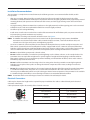
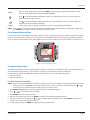
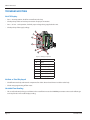
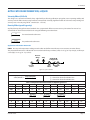
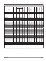
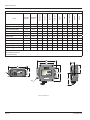
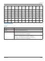
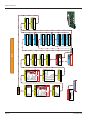
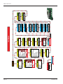
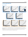
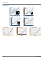
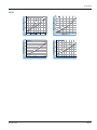
MR Flow Transmitter
RUN
Flow Transmitter
3500 PSI/241 BARS MAX
OIL
XMT-UM-00498-EN-02 (November 2013)
User Manual
MR Flow Transmitter
Page ii
November 2013
User Manual
CONTENTS
Introduction . . . . . . . . . . . . . . . . . . . . . . . . . . . . . . . . . . . . . . . . . . . . . . . . . . . . . . . . . . . . . . . . . . . . . . . . . 5
Safety Information . . . . . . . . . . . . . . . . . . . . . . . . . . . . . . . . . . . . . . . . . . . . . . . . . . . . . . . . . . . . . . . . . . . . . 5
Unpacking and Inspection . . . . . . . . . . . . . . . . . . . . . . . . . . . . . . . . . . . . . . . . . . . . . . . . . . . . . . . . . . . . . . . .5
Installation . . . . . . . . . . . . . . . . . . . . . . . . . . . . . . . . . . . . . . . . . . . . . . . . . . . . . . . . . . . . . . . . . . . . . . . . . . 6
Installation Recommendations . . . . . . . . . . . . . . . . . . . . . . . . . . . . . . . . . . . . . . . . . . . . . . . . . . . . . . . . . . .7
Electrical Connections . . . . . . . . . . . . . . . . . . . . . . . . . . . . . . . . . . . . . . . . . . . . . . . . . . . . . . . . . . . . . . . .7
Schematics . . . . . . . . . . . . . . . . . . . . . . . . . . . . . . . . . . . . . . . . . . . . . . . . . . . . . . . . . . . . . . . . . . . . . . . 8
Installing the Transmitter . . . . . . . . . . . . . . . . . . . . . . . . . . . . . . . . . . . . . . . . . . . . . . . . . . . . . . . . . . . . . 10
Operation . . . . . . . . . . . . . . . . . . . . . . . . . . . . . . . . . . . . . . . . . . . . . . . . . . . . . . . . . . . . . . . . . . . . . . . . . . 12
Operating the Meter . . . . . . . . . . . . . . . . . . . . . . . . . . . . . . . . . . . . . . . . . . . . . . . . . . . . . . . . . . . . . . . . 12
Normal Operation (RUN) Mode . . . . . . . . . . . . . . . . . . . . . . . . . . . . . . . . . . . . . . . . . . . . . . . . . . . . . . . . . 12
Programming Operation (PROGRAM) Mode . . . . . . . . . . . . . . . . . . . . . . . . . . . . . . . . . . . . . . . . . . . . . . . . . 12
Cover Removal/Reinstallation . . . . . . . . . . . . . . . . . . . . . . . . . . . . . . . . . . . . . . . . . . . . . . . . . . . . . . . . . . 13
Programming Procedures . . . . . . . . . . . . . . . . . . . . . . . . . . . . . . . . . . . . . . . . . . . . . . . . . . . . . . . . . . . . . 13
List Item Selection Procedure . . . . . . . . . . . . . . . . . . . . . . . . . . . . . . . . . . . . . . . . . . . . . . . . . . . . . . . . . . 13
Numeric Value Entry Procedure . . . . . . . . . . . . . . . . . . . . . . . . . . . . . . . . . . . . . . . . . . . . . . . . . . . . . . . . . 14
Programming Flow Chart . . . . . . . . . . . . . . . . . . . . . . . . . . . . . . . . . . . . . . . . . . . . . . . . . . . . . . . . . . . . . 14
Maintenance . . . . . . . . . . . . . . . . . . . . . . . . . . . . . . . . . . . . . . . . . . . . . . . . . . . . . . . . . . . . . . . . . . . . . . . . 17
Cartridge Cleaning . . . . . . . . . . . . . . . . . . . . . . . . . . . . . . . . . . . . . . . . . . . . . . . . . . . . . . . . . . . . . . . . . 17
Inspection . . . . . . . . . . . . . . . . . . . . . . . . . . . . . . . . . . . . . . . . . . . . . . . . . . . . . . . . . . . . . . . . . . . . . . . 17
Troubleshooting . . . . . . . . . . . . . . . . . . . . . . . . . . . . . . . . . . . . . . . . . . . . . . . . . . . . . . . . . . . . . . . . . . . . . . 18
No LCD Display . . . . . . . . . . . . . . . . . . . . . . . . . . . . . . . . . . . . . . . . . . . . . . . . . . . . . . . . . . . . . . . . . . . . 18
No Rate or Total Displayed . . . . . . . . . . . . . . . . . . . . . . . . . . . . . . . . . . . . . . . . . . . . . . . . . . . . . . . . . . . . 18
Unstable Flow Reading . . . . . . . . . . . . . . . . . . . . . . . . . . . . . . . . . . . . . . . . . . . . . . . . . . . . . . . . . . . . . . 18
Application Information, Liquid . . . . . . . . . . . . . . . . . . . . . . . . . . . . . . . . . . . . . . . . . . . . . . . . . . . . . . . . . . . . 19
Viscosity Effect (SUS/cSt) . . . . . . . . . . . . . . . . . . . . . . . . . . . . . . . . . . . . . . . . . . . . . . . . . . . . . . . . . . . . . 19
Density Effect (specific gravity) . . . . . . . . . . . . . . . . . . . . . . . . . . . . . . . . . . . . . . . . . . . . . . . . . . . . . . . . . 19
Specifications . . . . . . . . . . . . . . . . . . . . . . . . . . . . . . . . . . . . . . . . . . . . . . . . . . . . . . . . . . . . . . . . . . . . . . . 23
General . . . . . . . . . . . . . . . . . . . . . . . . . . . . . . . . . . . . . . . . . . . . . . . . . . . . . . . . . . . . . . . . . . . . . . . . 23
Materials . . . . . . . . . . . . . . . . . . . . . . . . . . . . . . . . . . . . . . . . . . . . . . . . . . . . . . . . . . . . . . . . . . . . . . . . 24
Flow vs Pressure Drop . . . . . . . . . . . . . . . . . . . . . . . . . . . . . . . . . . . . . . . . . . . . . . . . . . . . . . . . . . . . . . . . . . 29
Petroleum Fluids . . . . . . . . . . . . . . . . . . . . . . . . . . . . . . . . . . . . . . . . . . . . . . . . . . . . . . . . . . . . . . . . . . . 29
Phosphate Ester . . . . . . . . . . . . . . . . . . . . . . . . . . . . . . . . . . . . . . . . . . . . . . . . . . . . . . . . . . . . . . . . . . . 30
November 2013
Page iii
MR Flow Transmitter
API Oil . . . . . . . . . . . . . . . . . . . . . . . . . . . . . . . . . . . . . . . . . . . . . . . . . . . . . . . . . . . . . . . . . . . . . . . . . 31
Water-Based Fluids . . . . . . . . . . . . . . . . . . . . . . . . . . . . . . . . . . . . . . . . . . . . . . . . . . . . . . . . . . . . . . . . . 32
Water . . . . . . . . . . . . . . . . . . . . . . . . . . . . . . . . . . . . . . . . . . . . . . . . . . . . . . . . . . . . . . . . . . . . . . . . . . 33
Caustic and Corrosive Liquids . . . . . . . . . . . . . . . . . . . . . . . . . . . . . . . . . . . . . . . . . . . . . . . . . . . . . . . . . . 33
Air/Compressed Gases . . . . . . . . . . . . . . . . . . . . . . . . . . . . . . . . . . . . . . . . . . . . . . . . . . . . . . . . . . . . . . . 34
Air/Caustic and Corrosive Gases . . . . . . . . . . . . . . . . . . . . . . . . . . . . . . . . . . . . . . . . . . . . . . . . . . . . . . . . . 34
Page iv
November 2013
User Manual
INTRODUCTION
The MR flow transmitter is a state-of-the-art, microprocessor based variable area flow meter. It combines the rugged proven
technology of a piston-type, variable area flow meter with solid state circuitry including:
•
Non-contact sensor electronics
•
Electronic signal conditioning circuit
•
Digital flow rate and total indication
• Proportional analog output
The product is sealed against industrial contamination by a NEMA 12 and 13 (IP 52/54) rated enclosure and is available for
either liquid or gas service.
The MR flow transmitter is capable of calculating and displaying both flow rate and total accumulated flow. The flow rate and
total flow can be displayed in any of the user selectable measurement units. The monitor’s large 8 digit numeric liquid crystal
display makes extended range viewing practical. The second 8 character alphanumeric display provides for selectable units
viewing in RUN mode and prompts for variables in PROGRAM mode.
All MR flow transmitters come pre-calibrated from the factory. However, the unit may be adjusted by the user to meet
specific system requirements. Calibration parameters are included for:
•
Specific gravity compensation (all fluids)
•
Viscosity compensation (petroleum-based fluids)
• Pressure and temperature compensation (pneumatic applications)
All meters include an analog output that can be configured for 0…5V DC, 0…10V DC, or 4…20 mA current loop. Applications
for the MR flow transmitter include:
•
Bearing lubrication
•
Case drain verification
•
Gun drill and machine cooling
•
Pump flow outputs
SAFETY INFORMATION
The installation of this flow meter must comply with all applicable federal, state, and local rules, regulations, and codes.
Failure to read and follow these instructions can lead to misapplication or misuse of this product, resulting in personal injury
and damage to equipment.
UNPACKING AND INSPECTION
Upon opening the shipping container, visually inspect the product and applicable accessories for any physical damage such
as scratches, loose or broken parts, or any other sign of damage that may have occurred during shipment.
NNOTE: If damage is found, request an inspection by the carrier's agent within 48 hours of delivery and file a claim with the
carries. A claim for equipment damage in transit is the sole responsibility of the purchaser.
November 2013
Page 5
MR Flow Transmitter
INSTALLATION
THIS PRODUCT SHOULD BE INSTALLED AND SERVICED BY TECHNICALLY QUALIFIED PERSONNEL TRAINED IN
MAINTAINING INDUSTRIAL CLASS FLOW INSTRUMENTATION AND PROCESSING EQUIPMENT.
READ INSTRUCTIONS THOROUGHLY BEFORE INSTALLING THE UNIT. IF YOU HAVE ANY QUESTIONS REGARDING
PRODUCT INSTALLATION OR MAINTENANCE, CALL YOUR LOCAL SUPPLIER FOR MORE INFORMATION.
DISCONNECT ELECTRICAL POWER BEFORE OPENING WIRING ENCLOSURE. FAILURE TO FOLLOW THESE INSTRUCTIONS
COULD RESULT IN SERIOUS PERSONAL INJURY OR DEATH AND/OR DAMAGE TO THE EQUIPMENT.
ALL WIRING SHOULD BE INSTALLED IN ACCORDANCE WITH THE NATIONAL ELECTRICAL CODE® AND MUST CONFORM
TO ANY APPLICABLE STATE AND LOCAL CODES. FAILURE TO FOLLOW THESE INSTRUCTIONS COULD RESULT IN SERIOUS
PERSONAL INJURY OR DEATH AND/OR DAMAGE TO THE EQUIPMENT.
AIR/GAS METERS ARE NOT OXYGEN CLEANED. USE WITH OXYGEN MAY CAUSE HAZARDOUS OR EXPLOSIVE
CONDITIONS THAT MAY CAUSE SERIOUS PERSONAL INJURY AND/OR DAMAGE TO THE EQUIPMENT.
THIS METER MAY CONTAIN RESIDUAL AMOUNTS OF TEST FLUID AT THE TIME OF SHIPMENT. THIS FLUID SHOULD BE
REMOVED PRIOR TO INSTALLATION AS THE FLUID MAY BE INCOMPATIBLE OR HAZARDOUS WITH SOME LIQUIDS OR
GASES. FAILURE TO FOLLOW THESE INSTRUCTIONS COULD RESULT IN DAMAGE TO THE EQUIPMENT.
THIS STANDARD METER IS UNIDIRECTIONAL. ATTEMPTS TO FLOW FLUIDS IN THE OPPOSITE DIRECTION OF THE FLOW
ARROW WILL RESULT IN THE METER ACTING AS A CHECK VALVE, CREATING A DEADHEADING SITUATION. IF THE
DIFFERENTIAL PRESSURE MAGNITUDE IS GREAT ENOUGH, DAMAGE TO THE INTERNAL PARTS OF THE METER WILL
RESULT.
Page 6
November 2013
User Manual
Installation Recommendations
The transmitter is a simple device to install. However, the following measures are recommended for reliable, troublefree operation:
•
Align pipe accurately. Piping should be accurately aligned and of correct length. The high pressure body of the
transmitter can withstand shock and flow/pressure pulsation. However, the piping should be firmly supported by external
mounting brackets, both upstream and downstream of the meter, to avoid any pipe flexing actions that could reduce
meter life.
•
Use rigid mounting. If the transmitter inlet or outlet are to be rigidly mounted, and the opposing port is to be connected
to flexible hose, the end connected with the flexible hose must be rigidly mounted.
•
Use Teflon® tape for sealing NPT fitting.
•
Install unions. Install a union near the inlet or outlet of the transmitter. This will facilitate quick, easy meter removal and
inspection during periodic maintenance procedures.
•
Ensure the fluid is traveling in the direction of the flow arrow. See Figure 4.
NNOTE: The MR flow transmitter display board can be rotated 180° for optimal viewing. Simply remove the MR flow
transmitter cover, disconnect the ribbon cable, rotate the display board 180°, reconnect the ribbon cable, and
reinstall cover. See Figure 10 for cover screw tightening sequence.
•
Use at least a 200 mesh (74 micron) filter. The transmitter will allow particulate to pass that would jam most valves and
flow controls. Systems that do not have filtration should be equipped with at least a 200 mesh (74 micron) filter. Most
hydraulic systems already have much finer filtration. Dirt, ferrous metal or sealing agents, such as Teflon® tape may lodge
and cause malfunction. If the meter is jammed at a fixed position, follow cleaning and maintenance instructions.
• Do not use thread locking compounds as thread sealant.
• Do not install the transmitter near turbulence producing fittings such as elbows, reducers, or close coupled valves. The
transmitter does not require flow straighteners or special lengths of straight inlet/outlet piping to stabilize turbulent
flow patterns. However, to assure maximum operational reliability, avoid installation of elbows, valves and/or reducers
immediately adjacent to the meter inlet.
• Do not install the transmitter near fast-acting valves. Fast-acting valves have the potential to create high magnitude
hydraulic pressure spikes. These spikes can damage the internal components of the meter, resulting in inaccuracies
or malfunction.
• Do not allow unidirectional transmitters to be operated against the direction of the flow arrow. The standard transmitter
is a unidirectional flow meter. The piston acts as a check valve to block flow in the reverse direction. This causes an
excessive pressure differential, which can result in damage to internal meter components. The transmitter is also available
in a modified design, which offers a reverse flow bypass feature to accommodate bidirectional flow.
NNOTE: Transmitters with a reverse flow bypass feature are available. Consult factory for details.
Electrical Connections
Cable may be shortened or lengthened as required for proper installation. The cable is soldered directly to the electrical
connector at the factory.
Cable replacement requires disassembly of the electrical connector.
DC Output Connection
Loop Power Connection
No Connection
(-) 4…20 mA Out
2
3
3
4
1
1
0V DC
No Connection
4
(+) DC Power
(+) 4…20 mA In
0…5 or 0…10V DC Output
No Connection
2
Figure 1: 4-pin cable connection
November 2013
Page 7
MR Flow Transmitter
THE FLOW TRANSMITTER IS DESIGNED TO OPERATE ONLY ONE OF ITS THREE OUTPUTS AT A TIME (0…5V DC OR
0…10V DC OR 4…20 MA). CONNECTING MULTIPLE OUTPUTS SIMULTANEOUSLY WILL RESULT IN INACCURATE OUTPUT
SIGNAL LEVELS.
Schematics
The transmitter can be wired in various configurations to allow interface with many different types of data collection and
control instrumentation.
Schematics 1 & 2 (Figure 3) represent typical wiring for a target powered by either AC power or DC supply.
Schematics 3 & 4 (Figure 3) will be used when the flow transmitter is operated with loop-powered process indicators or data
loggers that do not have external sensor excitation available.
ENTER
Outlet Port
RUN
PROGRAM
RELAY 1
RELAY 2
MENU
Display Board
Transmitter
Connector
Sensor Board
Inlet Port
Figure 2: Terminology
Page 8
November 2013
User Manual
External DC
Sensor Excitation
Black
Green
2
3
4
1
4-20 mA Input
Red
White
Example:
Chart Recorder
Schematic 1: 4…20 mA connection using targets
power supply.
Sensor Excitation
2
3
4
1
Black
0-5 VDC Input
Green
0-10 VDC Input
Red
Ground
White
Example:
Chart Recorder
Schematic 2: 0…5 Vdc or 0…10 Vdc connection using
targets power supply.
Black
Green
2
3
4
1
Red
Excitation
Voltage
Fuse: 0.05 A Fast
4-20 mA Input (-)
4-20 mA Input (+)
White
Example:
Chart Recorder
Schematic 3: 4…20 mA connection using targets
external power supply.
Fuse: 0.05 A Fast
2
3
4
1
Black
0-5 VDC Input
Green
0-10 VDC Input
Red
Ground
White
Excitation
Voltage
Example:
Chart Recorder
Schematic 4: 0…5 Vdc or 0…10 Vdc connection using
targets external power supply.
Figure 3: Wiring diagrams
November 2013
Page 9
MR Flow Transmitter
3
er
i t t AX
sm S M
R
an
Tr 1 BA
ow 4
F l SI/2 OIL
0P
50
itte
nsm
Tr a0-MR
w
l o -00 W
F 00A
H6
del 0
Mo 7850
.:
2
S.N : 041
te
Da
r
FLO
Flow
Direction
Arrow
Flow
Inlet Port
Figure 4: Flow direction arrow
Installing the Transmitter
1.
2.
3.
4.
5.
Disconnect the electrical power from the target system before making or changing any transmitter connections.
Use 0.05 A fast-acting fuse if non-current limited power sources are used.
Terminate cable shield connection at either DC ground or earth ground.
Mount the transmitter so fluid is traveling in the direction of the flow arrow. See Figure 4.
Install unit in desired location. Use wrench on transmitter flats to hold the unit in place during installation. DO NOT TURN
the transmitter using the wrench. See Figure 5.
6. After installation, rotate the transmitter by hand to view the display. See Figure 6.
7. Capture the zero flow position on the meter cone using the ZERO CAPTURE procedure.
35
r
it te AX
sm M
RS
an
Tr 1 BA
o w 24 IL
I/
Fl
O
PS
00
Fl ow
sm
R
Tr an
0-M
00
00Ael H6 0
Mod 7850
.:
S.N : 0412
te
Da
it te
r
FLOW
Place wrench on transmitter flats on the same
side plumbing is being tightened
r
35
it te A
sm M
RS
an
Tr 1 BA
o w 24 IL
I/
Fl
O
PS
00
X
Fl ow
sm
R
Tr an
0-M
00
00Ael H6 0
Mod 7850
.:
S.N : 0412
te
Da
it te
r
FLOW
Never place wrench on transmitter flats
opposite plumbing being tightened
Figure 5: Installing the meter
Page 10
November 2013
User Manual
35
r
it te AX
sm M
RS
an
Tr BA
ow 41 IL
I/2 O
Fl
PS
00
Fl ow
sm
R
Tr an
0-M
00
00AH6
del 0
Mo 7850
.:
S.N 0412
te:
Da
it te
r
FLOW
Place wrench on transmitter flats on the
same side plumbing is being tightened
r
35
it te AX
sm M
RS
an
Tr BA
ow 41 IL
I/2 O
Fl
PS
00
Fl ow
sm
R
Tr an
0-M
00
00AH6
del 0
Mo 7850
.:
S.N 0412
te:
Da
it te
r
FLOW
Never place wrench on transmitter flats
opposite plumbing being tightened
Figure 6: Rotating meter
November 2013
Page 11
MR Flow Transmitter
OPERATION
Operating the Meter
The monitor has two modes of operation, referred to as RUN mode and PROGRAM mode as indicated on the display screen
readout. Normal operation will be in the run mode. To access the program mode, press MENU until the first programming
screen DISPLAY appears.
NNOTE: PROGRAM appears on left side of display.
After programming the meter, a password may be entered to prevent unauthorized access to programming.
Normal Operation (RUN) Mode
During normal operation, the transmitter will show RUN on the left side of the display. In RUN mode the flow rate and total
flow will alternate being shown as the default. The meter can also be set to show only flow rate or only flow total.
MENU
ENTER
Programming
Buttons
Figure 7: Programming buttons
The four buttons have the following function in RUN mode:
MENU
Selects programming mode.
No function.
No function.
ENTER
The current total can be manually stored in the monitor's flash memory. Press and hold ENTER for 2
seconds. The display will respond with a flashing TOTALSVD and then will return to RUN mode.
RESET TOTAL
To reset the monitor's total display, press MENU and ENTER simultaneously until TOTALRST starts to
flash. The TOTALRST will stop flashing and the display will return to RUN mode at the conclusion of the
rest procedure.
Programming Operation (PROGRAM) Mode
The programming mode lets you change the configuration and adjust the calibration of the meter. The MR flow transmitter
has two types of configuration changes accessible in program mode:
1. To view or change selections from a pre-defined list.
2. To view or change numeric entries.
During programming operation, the following four button functions are provided:
Page 12
November 2013
User Manual
MENU
Enters and exits programming mode. Press MENU once to change to programming mode. The mode
indicator on the display will change from RUN to PROGRAM.
Press
to scroll through the configuration choices in a bottom-to-top order. For numeric setup, this
button increments numeric values.
Use
to scroll through the configuration choices in a top-to-bottom order. For numeric setup, this
button moves the active digit to the right.
ENTER
Used to enter menus, to change configurations and to save programming information.
NNOTE: If any input value exceeds the meter’s capabilities, the LIMIT indicator will begin to flash indicating an invalid entry.
Press ENTER once to return to the entry screen to reenter the value.
Cover Removal/Reinstallation
It is necessary to remove the MR flow transmitter cover to access the programming keys. Use a Phillips screwdriver to remove
the four screws that hold the cover in place, turning them counterclockwise. When programming is completed, reinstall the
cover. To properly seat the built-in cover gasket, tighten the cover screws clockwise in a crisscross pattern as shown in Figure 8.
4
1
2
Flow Transmitter
3500 PSI/241 BARS MAX
OIL
3
Figure 8: Cover screw tightening sequence
Programming Procedures
The MR flow transmitter has been programmed at the factory according to the specifications that were provided at the time
of order. No further programming is required unless a change has occurred in the original specifications.
If programming is required, the MR flow transmitter allows two basic sets of programming procedures:
1. List Item Selection
2. Numeric Value Entry
List Item Selection Procedure
NNOTE: If you are already in PROGRAM mode and the selection to be viewed or changed is already displayed, proceed to step
3 below. If you are in PROGRAM mode and the selection to be viewed or changed is not displayed, press
or
and repeat pressing until the desired selection appears. Proceed to step 3.
1. Press MENU. PROGRAM appears in the lower left-hand corner and DISPLAY appears.
2. Press
or
to move to the desired selection.
3. Press ENTER to view the current selection.
4. If the current selection is desired, press ENTER to confirm. The unit will automatically advance.
5. If current selection must change, press
or
to scroll through the available choices. Press ENTER to confirm your
selection. The unit will automatically advance.
6. To exit programming, press MENU. The display will change to RUN mode.
November 2013
Page 13
MR Flow Transmitter
Numeric Value Entry Procedure
NNOTE: If you are already in PROGRAM mode and the desired selection is displayed, proceed to step 3 below. If you are in
PROGRAM mode and the desired selection is not displayed, press
or
and repeat pressing until the desired
selection appears. Proceed to step 3.
1. Press MENU. PROGRAM appears in the lower left-hand corner and DISPLAY appears.
2. Press
or
to move to the desired selection. The current numeric value for this selection appears in the upper section
of the display.
3. If the current displayed value is desired, press ENTER. The left most programmable number begins to flash. Press ENTER
again to confirm and keep the current setting. The unit will automatically advance.
4. If the current selection must change, press ENTER. The left most programmable number begins to flash. Use
to scroll
through the digits 0-9 and change the flashing digit to the desired value. Use
to move the active digit to the right.
Continue using the
and
until all desired digits are selected.
5. Press ENTER to confirm your selection. The unit will automatically advance.
6. To exit programming mode, press MENU. The display will change to RUN mode.
Programming Flow Chart
See the programming flow charts in “Application Information, Liquid” on page 19 for the menu structure of the MR flow
transmitter and the available configuration selections.
Basic Programming Descriptions
Display Mode
The meter can display RATE (flow rate) or TOTAL (total accumulated flow) or alternate between BOTH rate and total. Its
displayed name is DISPLAY and is viewed or changed using the List Item Selection Procedure.
Rate Units of Measure
The meter allows the selection of many common rate units. Its displayed name is RATE UNT and is viewed or changed using
the List Item Selection Procedure.
Rate (Time) Interval
The meter allows selection of several intervals based on time. Its displayed name is RATE INT and is viewed or changed using
the List Item Selection Procedure.
Total Units of Measure
If the total flow is being displayed, the units for the total must first be chosen. The monitor allows the choice of many common
totalization units. Its displayed name is TOTL UNT and is viewed or changed using the List Item Selection Procedure.
Total Display Multiplier
The meter has the ability to accumulate the flow total in multiples of ten. For example, if the most desirable totalization unit
is 1000 gallons, the monitor can easily be set up for this requirement. Once back in RUN mode, every time the total display
increments by one digit the actual total would be an additional 1000 gallons. At 1000 total gallons the total display would
read 1, at 3000 gallons the total display would read 3. This feature allows the unit to accumulate totals that would exceed the
8-digit display capacity. Table 2 lists the available selection choices. Its displayed name is TOTL EXP and is viewed or changed
using the List Item Selection Procedure.
Exponent
E-2
E-1
E0
E1
E2
E3
E4
E5
E6
Totalizer Multiplier
x 0.01 (÷100)
x 0.1 (÷100)
x 1 (no multiplier)
x 10
x 100
x 1000
x 10,000
x 100,000
x 1,000,000
Table 1: Total flow units
Page 14
November 2013
User Manual
Full Flow Rate
The full flow rate is used to span the meter. Its displayed name is FULL FLOW and is viewed or changed using the Numeric
Value Entry Procedure.
Zero Capture
The zero position of the meter cone must be set when installing the meter. To capture the zero calibration position, press
ENTER at the ZERO CAP prompt. NO will display. Press either arrow key to change to YES, then press ENTER to capture zero.
Viscosity Units (Displayed for OIL meters only)
The Viscosity Units parameter is used in conjunction with Viscosity to perform viscosity correction for oil applications. The
meter allows the selection of the viscosity units, SUS or cSt. Its displayed name is VIS UNIT and is viewed or changed using the
List Item Selection Procedure.
Viscosity (Displayed for OIL meters only)
Viscosity is used in conjunction with Viscosity Units to perform viscosity correction for oil applications. Enter the viscosity in
either SUS or cSt, depending on the viscosity units selected, of the oil that will be used. Its displayed name is VISCOSTY and is
viewed or changed using the Numeric Value Entry Procedure.
Operating Pressure Unit (Displayed for GAS meters only)
Operating Pressure Units is used in conjunction with Operating Pressure in gas applications to compensate for the actual
pressure being measured at the meter. The meter allows the selection of the operating pressure units, Bar or PSI. Its displayed
name is PRESUNIT and viewed or changed using the List Item Selection Procedure.
Operating Pressure (Displayed for GAS meters only)
Operating Pressure is used in conjunction with Operating Pressure Units in gas applications to compensate for the actual
pressure being measured at the meter. Enter the operating pressure in either Bar or PSI units, depending on the Operating
Pressure Units selected. Its displayed name is OP PRES and is viewed or changed using the Numeric Value Entry Procedure.
Operating Temperature Unit (Displayed for GAS meters only)
Operating Temperature Units is used in conjunction with Operating Temperature in gas applications to compensate for the
actual temperature of the gas being measured at the meter. The meter allows the selection of the operating temperature
units, °F or °C. Its displayed name is TMP UNIT and is viewed or changed using the List Item Selection Procedure.
Operating Temperature (Displayed for GAS meters only)
Operating Temperature is used in conjunction with Operating Temperature Units in gas applications to compensate for the
actual temperature of the gas being measured at the meter. Enter the operating temperature in either °F or °C, depending on
the Operating Temperature Units selected. Its displayed name is OP TEMP and is viewed or changed using the Numeric Value
Entry Procedure.
Specific Gravity Correction Factor
Specific Gravity is used to compensate for the specific gravity of the liquid or gas being measured with the meter. Its displayed
name is SP GRAV and is viewed or changed using the Numeric Value Entry Procedure.
Damping
The Damping factor is increased to enhance the stability of the flow readings. Damping values are decreased to allow the flow
meter to react faster to changing values of flow. This parameter can range from 0 to 99; factory default is 0. Its displayed name
is DAMPING and is viewed or changed using the Numeric Value Entry Procedure.
Output Mode
The MR flow transmitter offers three analog output modes:
•
4…20 mA Output Signal
•
0…5 Volts DC Output Signal
• 0…10 Volts DC Output Signal
The output mode selected is determined by the type of peripheral device being connected to the MR flow transmitter.
The displayed name is OUT MODE and is viewed or changed using the List Item Selection Procedure.
NNOTE: Setup prompts and descriptors for configuring and calibrating the analog output will correspond to the output
mode selected.
November 2013
Page 15
MR Flow Transmitter
Password
Password protection prevents unauthorized users from changing programming information. Initially the password is set to all
zeros. Its displayed name is PASSWORD and is viewed or changed using the Numeric Value Entry Procedure.
Restore Defaults
This feature allows you to restore factory calibration data. Its displayed name is RES DFLT. To restore factory calibration data,
select YES, then press ENTER.
Advanced Programming Descriptions
Advanced programming allows the user access to re-configure the analog output. Calibration of the analog output is preset
at the factory, but can be changed to customize calibration for your installation.
To access the Advanced Programming Options, press and hold MENU for approximately 3 seconds until DISPLAY is viewed on
the display panel. The programming menus will begin with display mode DISPLAY and continue as described above through
output mode OUT MODE.
After output mode has been entered, Advanced Programming starts with the following:
Calibration of Analog Output
This selection allows access to the calibration and testing of the analog output signal.
To test or change the analog output calibration, it is first necessary to change the default setting for CAL OUT? from NO to YES.
NNOTE: Setup prompts and descriptors for configuring and calibrating the analog output will correspond to the output
mode selected. Refer to the Flow Chart.
1. At the CAL OUT? prompt press ENTER. NO will display.
2. To change to YES, press either arrow key.
3. The analog output will go to its minimum output level. A numeric value between 0-4000 will display. This is an internal
number used to drive the analog output.
4. To increase the analog output signal level, press
. To decrease the analog output signal level, press
.
5. Press ENTER to store the setting.
6. The analog output will go to its maximum output level. A numeric value between 0-4000 will display. This is an internal
number used to drive the analog output.
7. To increase the analog output signal level, press
. To decrease the analog output signal level, press
.
8. Press ENTER to store the setting.
9. The unit will advance to the analog output test mode. The analog output will go to its minimum output level. A numeric
value of 0 will display. For test purposes, the analog output signal can be run up or down in increments of 1 milliamp or 1
volt, depending on the OUT MODE selected.
10.To increase the analog output signal level, press
. To decrease the analog output signal level, press
.
11.Press ENTER to exit the analog calibration mode.
12.The unit automatically advances to the PASSWORD feature.
Password
Password protection prevents unauthorized users from changing programming information. Initially the password is set to all
zeros. Its displayed name is PASSWORD and is viewed or changed using the Numeric Value Entry Procedure f.
Restore Defaults
This feature allows you to restore factory calibration data. Its displayed name is RES DFLT. To restore factory calibration data,
select YES, then press ENTER.
Page 16
November 2013
User Manual
MAINTENANCE
BEFORE ATTEMPTING TO REMOVE THE TRANSMITTER FROM THE LINE, CHECK THE SYSTEM TO CONFIRM THAT LINE
PRESSURE HAS BEEN REDUCED TO ZERO PSI. FAILURE TO FOLLOW THESE INSTRUCTIONS COULD RESULT IN SERIOUS
PERSONAL INJURY OR DEATH AND/OR DAMAGE TO THE EQUIPMENT.
DISCONNECT ELECTRICAL POWER BEFORE REMOVING METER COVER. FAILURE TO FOLLOW THESE INSTRUCTIONS
COULD RESULT IN SERIOUS PERSONAL INJURY OR DEATH AND/OR DAMAGE TO THE EQUIPMENT.
Cartridge Cleaning
1. Disconnect the transmitter cable.
2. Remove the meter from the line. Remove excess piping from the transmitter. See Figure 4 and Figure 5.
NNOTE: It is not necessary to remove the aluminum housing from the transmitter to remove it from the line.
3. Thoroughly wipe off the entire transmitter surface using mild detergent or isopropyl alcohol.
DO NOT USE AROMATIC HYDROCARBONS, HALOGENATED HYDROCARBONS, KETONES OR ESTER BASED FLUIDS ON
POLYCARBONATE LENS. FAILURE TO FOLLOW THESE INSTRUCTIONS COULD RESULT IN DAMAGE TO THE TRANSMITTER.
4. Remove the inlet port cap, wave spring, retaining ring, and cone assembly from the transmitter body (Figure 9).
5. Gently push the body towards the outlet port.
6. The piston, inner magnet and transmitter spring are secured within the transmitter body with a retaining ring. Remove the
retaining ring with a small screwdriver, then the internal components can be removed from the body (Figure 9).
NNOTE: If internal parts do not slide freely from cartridge, use a wooden dowel inserted into the outlet port of the meter to
push parts out.
7. Place all parts on a clean work surface. Clean and inspect all parts. Replace any that appear worn or damaged. Check inlet
port O-ring for damage and replace if required.
FIELD REPLACEMENT OF THE SPRING, METERING CONE AND/OR PISTON/MAGNET ASSEMBLY MAY RESULT IN CHANGES
TO THE CALIBRATION OF THE FLOW METER.
8. Reassemble the transmitter by inserting the transmitter spring into the body, followed by the piston/inner magnet
assembly. A slight compression of the piston against the spring is required during installation of the retaining ring.
9. Gently push body assembly into the outlet end of the transmitter enclosure. The flat surface of the body output port
should be flush with the transmitter enclosure opening.
10.With the transmitter positioned vertically on a flat surface, inlet port facing up, install the transmitter cone assembly and
wave spring into the body and secure with the inlet port end cap.
11.Reinstall transmitter to the line. Reconnect electrical power.
Inspection
1. Frequent inspection should be made. The environment and frequency of use should determine a schedule for
maintenance checks. It is recommended that it should be at least once a year.
2. Perform visual, electrical, and mechanical checks on all components on a regular basis.
3. Visually check for undue heating evidence such as discoloration of wires or other components, damaged or worn parts, or
leakage evidence such as water or corrosion in the interior.
4. Make sure all electrical connections are clean and tight and that the device is wired properly.
November 2013
Page 17
MR Flow Transmitter
TROUBLESHOOTING
No LCD Display
•
For 4…20 mA operation, check for current flow in the loop.
•
Check polarity of the current loop connections for proper orientation.
•
For 0…5V or 0…10V operation, check for proper voltage being supplied to the unit.
•
Check polarity of the supply voltage.
1
ENTER
2
RUN
PROGRAM
RELAY 1
RELAY 2
MENU
3
4
5
6
7
Figure 9: Cartridge components
Number Name
1
Body
2
Cone Assembly
3
Meter Spring
4
Piston Assembly
5
Retaining Spring
6
Cap
7
Wave Spring
No Rate or Total Displayed
•
Check flow meter body and internal components for debris. Piston should move inside the tube freely.
•
Check setup programming of flow meter.
Unstable Flow Reading
•
This usually indicated pulsing or oscillation in the actual flow. Increase the DAMPING parameter to increase the filtering in
order to provide a more stable display reading.
Page 18
November 2013
User Manual
APPLICATION INFORMATION, LIQUID
Viscosity Effect (SUS/cSt)
The design uses a precision machined, sharp- edged orifice and biasing calibration spring that assures operating stability and
accuracy over the wide viscosity range common to many fluids. Generally, high flow models of each meter size provide good
accuracy over a viscosity range of 40…500 SUS (4.2…109 cSt).
Density Effect (specific gravity)
Any fluid density change from stated standards has a proportional effect on meter accuracy. Corrections for more or less
dense fluids can be made to standard scales using the following correction factor:
1.0
Specific Gravity
For water/water-based meters
0.876
Specific Gravity
For petroleum-based meters
Application Information Pneumatic
NNOTE: Pressure and temperature readings must be taken at the flow meter inlet to ensure accurate correction factors.
The pneumatic flow meter is calibrated for air in standard cubic feet per minute (scfm) at 1.0 s.g. (70° F @ 100 psi), and liter per
second (lps) at 1.0 s.g. (21° C @ 6.9 bar).
Pressure
Gauge
Temp
Air Bleed Off
To Equipment
Pressure
Source
Flow
Meter
Adjustable
Valve
Figure 10: System schematic
DETERMINE FLOW RATES USING DIFFERENT PRESSURES & TEMPERATURES
Where
scfm ( indicated )
scfm ( actual ) =
f1x f 2 x f3
f1 = Conversion Factor for Inlet Pressure
f2 = Conversion Factor for Inlet Pressure
f3 = Conversion Factor for Inlet Pressure
Table 1–Temperature Correction Factor (f1) Operating Pressure
psig
25
50
75
100
125
150
175
200
225
250
BAR
1.7
3.5
5.2
6.9
8.6
10.4
12.1
13.8
15.5
17.2
kPa
172
345
517
689
862
1034
1207
1379
1551
1724
f1
1.700
1.331
1.131
1.00
0.902
0.835
0.778
0.731
0.692
0.658
f1 =
114.7
14.7 + psig
f1 =
7.914
1.014 + BAR
f1 =
790.857
101.357 + kPa
Table 2–Temperature Correction Factor (f2)
°F
10
30
50
70
90
110
130
150
170
190
°C
–12.2
–1.1
9.9
21.0
32.1
43
54
65
76
88
f2
0.942
0.962
0.981
1.00
1.018
1.037
1.055
1.072
1.090
1.107
November 2013
Page 19
MR Flow Transmitter
f2 =
460 + ° F
530
f2 =
273 + °C
293
Table 3–Specific Gravity Correction Factor (f3)
f3 =
Sp.Gr .
Table 2: Conversion factors
NNOTE: Table 2 is included to show the correction algorithms include in the program to perform pressure, temperature,
and specific gravity corrections. When configuring the MR flow transmitter, enter the actual operating pressure,
temperature, and specific gravity values, not the correction factors.
Page 20
November 2013
User Manual
LIQUIDS
Specific
Gravity
Oil
Water
Aluminum
Brass
T16 SST
T303 SST
Viton®
EPR
Polycarbonate
Nylon
Pyrex®
Correction Factor
Acetic Acid (Air Free)
1.06
0.909
0.971
C
N
R
R
R
R
C
N
R
Acetone
0.79
1.053
1.125
R
R
R
R
N
R
N
R
R
Alcohol Butyl (Butanol)
0.83
1.027
1.098
C
C
R
R
C
R
R
R
R
Alcohol Ethyl (Ethanol)
0.83
1.027
1.098
C
C
R
R
C
R
R
N
R
Ammonia
0.89
0.992
1.060
R
C
R
R
N
R
N
C
R
Benzine
0.69
1.127
1.204
C
R
R
C
R
N
N
R
R
Carbon Disulphide
1.26
0.834
0.891
R
N
R
R
R
N
N
R
R
Castor Oil
0.97
0.950
1.015
C
R
R
C
R
N
C
C
R
Cotton Seed Oil
0.93
0.970
1.037
C
R
R
R
R
N
R
R
R
Ethylene Glycol 50/50
1.12
0.884
0.945
R
R
R
R
R
R
R
C
R
Freon II
1.46
0.774
0.828
R
R
R
R
R
N
R
R
R
Gasoline
0.70
1.119
1.195
R
R
R
R
R
N
C
R
R
Glycerin
1.26
0.834
0.891
R
R
R
R
R
R
R
C
R
Kerosene
0.82
1.033
1.104
R
R
R
R
R
N
R
R
R
Liquid Propane (LPG)
0.51
1.310
1.400
R
R
R
R
R
N
N
R
R
Mineral Oil
0.92
0.976
1.042
R
N
R
R
R
N
R
R
R
Naphtha
0.76
1.074
1.147
R
N
R
R
R
N
C
R
R
Perchloroethylene
1.62
0.735
0.786
C
N
R
R
R
N
N
N
R
Petroleum Oil
0.876
1.000
1.068
R
R
R
R
R
N
R
R
R
Phosphate Ester
1.18
0.862
0.921
R
R
R
R
N
R
N
R
R
Phosphate Ester Base
1.26
0.833
0.891
R
R
R
R
N
R
N
R
R
Phosphoric Acid (Air Free)
1.78
0.701
0.749
N
N
R
N
R
N
R
N
R
Sea Water
1.03
0.922
0.985
N
N
C
C
N
R
R
R
R
Synthetic Petroleum Base
1.00
0.936
1.000
R
C
R
R
R
N
R
R
R
Water
1.00
0.936
1.000
N
R
R
R
N
R
R
R
R
Water Glycol 50/50
1.07
0.905
0.967
R
R
R
R
R
N
R
R
R
Water-in-oil
0.93
0.970
1.037
R
R
R
R
N
R
R
R
R
Fluid
R–Recommended
N–Not Recommended
C–Consult Factory
Table 3: Liquids Fluid selection chart
November 2013
Page 21
MR Flow Transmitter
Aluminum
Brass
T16 SST
T303 SST
Viton®
EPR
Polycarbonate
Nylon
Pyrex®
LIQUIDS
Air
1.0
1.000
R
R
R
R
R
R
R
R
R
Argon (A)
1.38
1.175
R
R
R
R
R
R
R
R
R
Carbon Dioxide (CO2)
1.53
1.237
R
R
R
R
R
R
R
R
R
Freon 11 (CCI3F)
4.92
2.218
R
R
R
R
R
R
R
R
R
Freon 12 (CCI2F)
4.26
2.060
R
R
R
R
R
R
R
R
R
Helium (HE)
0.14
0.374
R
R
R
R
R
R
R
R
R
Hydrogen (H2)
0.07
0.265
R
R
R
R
R
R
R
R
R
Natural Gas
0.60
0.775
C
C
R
C
R
N
C
R
R
Nitrogen (N2)
0.97
0.985
C
C
R
R
R
R
C
R
R
Oxygen (O2)
1.10
1.049
R
R
R
R
R
R
R
R
R
Propane C3H8)
1.57
1.253
R
R
R
R
R
N
N
R
R
Specific Correction
Gravity
Factor
Fluid
R–Recommended
N–Not Recommended
C–Consult Factory
Table 4: Gaseous fluid selection chart
D
C
J
B
G
Flow Transmitter
Model H600A-000-MR
S.N.: 78500
FLOW
Date: 0412
I
F E
3
RUN
1
2
A
4
Flow Transmitter
3500 PSI/241 BARS MAX
OIL
H
K
Figure 11: Dimensions
Page 22
November 2013
User Manual
A
Nominal
Port Size
B
Length
in.
(mm)
C
Length
in.
(mm)
D
Length
in.
(mm)
E
Width
in.
(mm)
F
Width
in.
(mm)
G
Width
in.
(mm)
H
Width
in.
(mm)
I
Depth
in.
(mm)
J
Offset
in.
(mm)
K
Hole
Dia. in.
(mm)
1/4
(SAE 6)
6.60
(168)
5.27
(134)
6.41
(163)
6.00
(152)
3.23
(82)
3.00
(76)
4.20
(107)
2.94
(75)
1.51
(38)
0.31
(8)
1/2
(SAE 10)
6.60
(168)
5.27
(134)
6.41
(163)
6.00
(152)
3.23
(82)
3.00
(76)
4.20
(107)
2.94
(75)
1.51
(38)
0.31
(8)
3/4
(SAE 12)
7.20
(183)
5.27
(134)
7.04
(179)
6.00
(152)
3.60
(91)
3.00
(76)
4.20
(107)
2.94
(75)
1.27
(32)
0.31
(8)
1
(SAE 16)
7.20
(183)
5.27
(134)
7.04
(179)
6.00
(152)
3.60
(91)
3.00
(76)
4.20
(107)
2.94
(75)
1.27
(32)
0.31
(8)
1-1/4
(SAE 20)
12.20
(310)
10.68
(271)
11.65
(296)
7.63
(194)
4.84
(123)
3.82
(97)
5.02
(128)
4.50
(114)
2.20
(56)
0.31
(8)
1-1/2
(SAE 24)
12.20
(310)
10.68
(271)
11.65
(296)
7.63
(194)
4.84
(123)
3.82
(97)
5.02
(128)
4.50
(114)
2.20
(56)
0.31
(8)
SPECIFICATIONS
General
Accuracy
± 2% of full scale
Repeatability
± 1%
Threads
SAE J1926/1, NPTF ANSI B2.2, BSPP IS01179
Temperature Range
–20…240° F (–29…116° C)
Pressure Rating
Aluminum/Brass Operating
Liquids: 3500 psi/241 bar maximum (3:1 safety factor)
Gases: 1000 psi/69 bar maximum (10:1 safety factor)
Stainless Steel Operating
Liquids (1/4…1/2"): 6000 psi/414 bar maximum (3:1 safety factor)
Liquids (3/4…1-1/2"): 5000 psi/345 bar maximum (3:1 safety factor)
Gases: 1500 psi/103 bar maximum (10:1 safety factor)
November 2013
Page 23
MR Flow Transmitter
Materials
All Meters Common
Parts
2024 – T351 Anodized aluminum body, piston and cone
C360 Brass body, piston and cone
T303 Stainless body, 2024 – T351 Anodized aluminum piston and con (Oil, PE WBF, & Air meters)
T303 Stainless body, C360 Brass piston and con (Water meters)
T316 Stainless body, piston and cone
Petroleum (Oil)
Common Parts
Spider Plate
Retaining Ring
Spring
Retaining Spring
Fasteners
Internal Magnet
Pressure Seals
Enclosure Seal
Lens
T316 SS
SAE 1070/1090 Carbon Steel
302 SS
SAE 1070/1090 Carbon Steel
T303 SS
Teflon® Coated Alnico 8
Viton®
Silicon gasket
Polycarbonate
Phosphate Ester (PE)
Common Parts
Spider Plate
Retaining Ring
Spring
Retaining Spring
Fasteners
Internal Magnet
Pressure Seals
Enclosure Seal
Lens
T316 SS
SAE 1070/1090 Carbon Steel
302 SS
SAE 1070/1090 Carbon Steel
T303 SS
Teflon Coated Alnico 8
EPR
Silicon gasket
Polycarbonate
Water-Based (WBF),
Water, Air Common
Parts
Spider Plate
Retaining Ring
Spring
Retaining Spring
Fasteners
Internal Magnet
Pressure Seals
Enclosure Seal
Lens
T316 SS
T316 SS
T302 SS
T316 SS
T303 SS
Teflon Coated Alnico 8
Viton
Silicone gasket
Polycarbonate
API Oil/Air/Caustic/
Corrosive Liquids and
Gases Common Parts
Spider Plate
Retaining Ring
Spring
Retaining Spring
Fasteners
Internal Magnet
Pressure Seals
Enclosure Seal
Lens
T316 SS
T316 SS
T316 SS
T316 SS
T316 SS
Teflon Coated Alnico 8
Viton
Silicone gasket
Polycarbonate
Page 24
November 2013
User Manual
High Cycle
Applications:
Pressure Fatigue
Rating
Per NFPA/T2.6.1 R1 - 1991, C/90, the method of verifying rated fatigue pressure (or establishing
the rated burst pressure, or both) of the pressure containing envelope conforms to NFPA/T2.6.1
R1, Fluid power systems and products – Method for verifying the fatigue and establishing the
burst pressure ratings of the pressure containing envelope of a metal fluid power component.
Meter Size
Aluminum
Brass
RFP*
Cycles
RFP*
1/4
2000
6
1×10
1/2
2000
3/4
1
1-1/4
1-1/2
Stainless Steel
RFP*
Cycles
**
3000
1×10⁶
1×10⁶
**
3000
1×10⁶
1500
1×10⁶
**
3000
1×10⁶
1500
1×10⁶
**
3000
1×10⁶
1000
1×10⁶
**
3000
1×10⁶
1500
70×103
**
3000
1×10⁶
1000
1×10
**
3000
1×10⁶
1500
70×103
**
3000
1×10⁶
6
Cycles
*RFP = Rated Fatigue Pressure
**Consult Factory
November 2013
Page 25
Page 26
Press and HOLD MENU
button until “PROGRAM”
appears.
ADVANCED FUNCTION
Seconds
Minutes
Hours
Days
Rate Time Unit
RATE INT
Gallons
Liters
Million Gallons
Ft³
Meters³
Million Liters
Acre Feet
Oil Barrel
Liquor Barrel
Mass
Pounds
Kilograms
Rate Unit / Time
RATE UNT
Rate
Total
Both
Test
Display Options
DISPLAY
Setting
SETTING NAME
START
Numeric Entry
Full Flow Rate
FULLFLOW
E-2 = × 0.01 (÷100)
E-1 = × 0.1 (÷10)
E0 = × 1 (no multiplier)
E1 = × 10
E2 = × 100
E3 = × 1,000
E4 = × 10,000
E5 = × 100,000
E6 = × 1,000,000
Totalizer Exponent
TOTL EXP
Gallons
Liters
Million Gallons
Ft³
Meters³
Million Liters
Acre Feet
Oil Barrel
Liquor Barrel
Mass
Pounds
Kilograms
Totalizer Unit
TOTL UNT
Output Mode
Calibrate Output?
Yes
No
CAL OUT?
4 - 20 mA
0 - 5 VDC
0 - 10 VDC
OUT MODE
Numeric Entry
SP GRAV
Specific Gravity
Numeric Entry
VISCOSITY
Viscosity Value
Visc SUS
Visc CST
Viscosity Unit
VIS UNIT
No
Yes
Zero Capture
ZERO CAP
Oil
4-20TEST
FLOW 0V
Single Digit Increments
Flow at 10 Volts
0-10TEST
Numeric Entry
Flow at 10 Volts
FLOW 10V
Numeric Entry
Flow at 0 Volts
Single Digit Increments
Flow at 5 Volts
0-5 TEST
Numeric Entry
FLOW 5V
Flow at 5 Volts
Numeric Entry
FLOW 0V
Flow at 0 Volts
Single Digit Increments
Test Output
Numeric Entry
Flow at 20 mA
FLOW20MA
Numeric Entry
FLOW 4MA
Flow at 4 mA
Reset to Default
No
Yes
RES DFLT
MENU
Numeric Entry
PASSWORD
Password
ENTER
MR Flow Transmitter
November 2013
November 2013
Press and HOLD MENU
button until “PROGRAM”
appears.
ADVANCED FUNCTION
Seconds
Minutes
Hours
Days
Rate Time Unit
RATE INT
Gallons
Liters
Million Gallons
Ft³
Meters³
Million Liters
Acre Feet
Oil Barrel
Liquor Barrel
Mass
Pounds
Kilograms
Rate Unit / Time
RATE UNT
Rate
Total
Both
Test
Display Options
DISPLAY
Setting
SETTING NAME
START
Totalizer Unit
TOTL UNT
Numeric Entry
FULLFLOW
Full Flow Rate
E-2 = × 0.01 (÷100)
E-1 = × 0.1 (÷10)
E0 = × 1 (no multiplier)
E1 = × 10
E2 = × 100
E3 = × 1,000
E4 = × 10,000
E5 = × 100,000
E6 = × 1,000,000
Totalizer Exponent
TOTL EXP
Gallons
Liters
Million Gallons
Ft³
Meters³
Million Liters
Acre Feet
Oil Barrel
Liquor Barrel
Mass
Pounds
Kilograms
Zero Capture
ZERO CAP
DAMPING
Output Mode
Yes
No
Calibrate Output?
CAL OUT?
4 - 20 mA
0 - 5 VDC
0 - 10 VDC
OUT MODE
Numeric Entry
Display Damping
Numeric Entry
Specific Gravity
SP GRAV
No
Yes
Water
FLOW 4MA
Flow at 4 mA
FLOW 5V
Single Digit Increments
Flow at 10 Volts
0-10TEST
Numeric Entry
Flow at 10 Volts
FLOW 10V
Numeric Entry
FLOW 0V
Flow at 0 Volts
Single Digit Increments
Flow at 5 Volts
0-5 TEST
Numeric Entry
Flow at 5 Volts
Numeric Entry
FLOW 0V
Flow at 0 Volts
Single Digit Increments
4-20TEST
Test Output
Numeric Entry
Flow at 20 mA
FLOW20MA
Numeric Entry
PASSWORD
Password
Reset to Default
No
Yes
RES DFLT
MENU
Numeric Entry
ENTER
User Manual
Page 27
Page 28
Press and HOLD MENU
button until “PROGRAM”
appears.
ADVANCED FUNCTION
Seconds
Minutes
Hours
Days
Rate Time Unit
RATE INT
Gallons
Liters
Million Gallons
Ft³
Meters³
Million Liters
Acre Feet
Oil Barrel
Liquor Barrel
Mass
Pounds
Kilograms
Rate Unit / Time
RATE UNT
Rate
Total
Both
Test
Display Options
DISPLAY
Setting
SETTING NAME
START
No
Yes
Zero Capture
ZERO CAP
Numeric Entry
FULLFLOW
Full Flow Rate
E-2 = × 0.01 (÷100)
E-1 = × 0.1 (÷10)
E0 = × 1 (no multiplier)
E1 = × 10
E2 = × 100
E3 = × 1,000
E4 = × 10,000
E5 = × 100,000
E6 = × 1,000,000
Totalizer Exponent
TOTL EXP
Gallons
Liters
Million Gallons
Ft³
Meters³
Million Liters
Acre Feet
Oil Barrel
Liquor Barrel
Mass
Pounds
Kilograms
Totalizer Unit
TOTL UNT
Temperature Units
SP GRAV
Output Mode
Calibrate Output?
Yes
No
CAL OUT?
4 - 20 mA
0 - 5 VDC
0 - 10 VDC
OUT MODE
Numeric Entry
Specific Gravity
Numeric Entry
OP TEMP
Operating Temperature
DEGREE F
DEGREE C
TMP UNIT
Numeric Entry
Operating Pressure
OP PRES
PSI
BAR
Pressure Units
PRESUNIT
Air/Gases
4-20TEST
FLOW 0V
Single Digit Increments
0-10TEST
Flow at 10 Volts
Numeric Entry
FLOW 10V
Flow at 10 Volts
Numeric Entry
Flow at 0 Volts
Single Digit Increments
Flow at 5 Volts
0-5 TEST
Numeric Entry
FLOW 5V
Flow at 5 Volts
Numeric Entry
FLOW 0V
Flow at 0 Volts
Single Digit Increments
Test Output
Numeric Entry
Flow at 20 mA
FLOW20MA
Numeric Entry
FLOW 4MA
Flow at 4 mA
Reset to Default
No
Yes
RES DFLT
MENU
Numeric Entry
PASSWORD
Password
ENTER
MR Flow Transmitter
November 2013
User Manual
FLOW VS PRESSURE DROP
Petroleum Fluids
.10-1.0
.02-.20 .05-.50
1-10
0.5-5.0
0.1-1.0
0.2-2.0
FLOW, GPM
3-30
0
10-200
3/4"/1" Reverse Flow
1-15
1-10
0.5-5.0
0.2-2.0
0
10
20-300
1-1/4"/1-1/2" Reverse Flow
3-30
2-20
0.5-5.0
1-10
FLOW, GPM
PRESSURE DROP, PSI
4-40
PRESSURE DROP, PSI
PRESSURE DROP, PSI
5
FLOW, GPM
0.2-2.0
FLOW, GPM
10
PRESSURE DROP, PSI
PRESSURE DROP, PSI
10-75
5-50
1-10
0.1-1.0
2-20
3.0"
FLOW, GPM
0.5-5.0
3-30
FLOW, GPM
10-150
10-100
1/2" Reverse Flow
5-50
4-40
FLOW, GPM
1-1/4"/1-1/2"
0.2-2.0
3/4"/ 1"
1-15
PRESSURE DROP, PSI
PRESSURE DROP, PSI
PRESSURE DROP, PSI
1/2"
.20-2.0
1/4"
10-150
10-100
10-75
5-50
3-30
FLOW, GPM
The pressure drop curves are valid for fluids with density and viscosity similar to factory test fluids. Fluids, especially with
higher viscosity than theses test fluids, will yield a higher pressure drop through the flow meter and piping system per a given
flow volume.
A system must have adequate fluidic horsepower available to move the system fluid at a prescribed rate at a pressure
adequate to overcome all pressure reducing devices, including the flow meter.
November 2013
Page 29
MR Flow Transmitter
Phosphate Ester
0.20-2.0
1/4"
1/2"
1-15
.02-.20
.05-.50
4
2
0
0.0
1-10
0.5-5.0
2
0
0.5
FLOW, GPM
5-50
PRESSURE DROP, PSI
PRESSURE DROP, PSI
3-30
0.5-5.0
6
2-20
4
1-10
0.2-2.0
2
1-15
10-75
5-50
3-30
0 1 2 3 4 5
PRESSURE DROP, PSI
PRESSURE DROP, PSI
3/4"/1" Reverse Flow
2-20
0.5-5.0
1-10
1-1/4"/1-1/2" Reverse Flow
4-40
3-30
0.2-2.0
FLOW, GPM
Page 30
FLOW, GPM
0.5-5.0
0.1-1.0
2 2.5
10-100
FLOW, GPM
0.2-2.0
1
10-150
1-1/4" / 1-1/2"
4-40
0
1-10
0
FLOW, GPM
3/4"/ 1"
1/2" Reverse Flow
0.2-2.0
0.1-1.0
4
PRESSURE DROP, PSI
6
PRESSURE DROP, PSI
PRESSURE DROP, PSI
0.10-1.0
10-100
10-75
3-30
FLOW, GPM
10-150
5-50
FLOW, GPM
November 2013
User Manual
API Oil
1/2"
.20-2.0
PRESSURE DROP, PSI
PRESSURE DROP, PSI
1/4"
.10-1.0
0.5-5.0
0.2-2.0
4-40
3-30
2-20
FLOW, GPM
PRESSURE DROP, PSI
1-1/4"/ 1-1/2"
3/4" / 1"
PRESSURE DROP, PSI
1-10
FLOW, GPM
FLOW, GPM
November 2013
1-15
10-100
10-75
5-50
3-30
FLOW, GPM
Page 31
MR Flow Transmitter
Water-Based Fluids
1/2"
PRESSURE DROP, PSI
PRESSURE DROP, PSI
0.2-2.0
.05-.50
1-10
0.5-5.0
0.1-1.0
0.2-2.0
10-100
10-75
5-50
3-30
1-1/4"/1-1/2" Reverse Flow
4-40
PRESSURE DROP, PSI
PRESSURE DROP, PSI
Page 32
0.2-2.0
FLOW, GPM
3-30
2-20
0.5-5.0
0.2-2.0
FLOW, GPM
1-10
20-275
3/4"/1" Reverse Flow
1-15
0.5-5.0
2-20
PRESSURE DROP, PSI
PRESSURE DROP, PSI
10-150
0.1-1.0
3-30
20-180
FLOW, GPM
0.2-2.0
4-40
FLOW, GPM
3"
1-1/4"/ 1-1/2"
1-10
5-50
FLOW, GPM
FLOW, GPM
1/2" Reverse Flow
3/4" / 1"
1-15
PRESSURE DROP, PSI
.20-2.0
.10 -1.0
0.5-5.0
PRESSURE DROP, PSI
1/4"
10-150
10-100
10-75
5-50
1-10
3-30
FLOW, GPM
FLOW, GPM
November 2013
User Manual
Water
1/2"
0.2-2.0
.05-.50
3/4" / 1"
1-15
PRESSURE DROP, PSI
.20-2.0
.10 -1.0
PRESSURE DROP, PSI
PRESSURE DROP, PSI
1/4"
1-10
0.5-5.0
0.1-1.0
0.2-2.0
4-40
3-30
2-20
10-75
5-50
3-30
15-150
3"
PRESSURE DROP, PSI
PRESSURE DROP, PSI
10-100
1-10
FLOW, GPM
1-1/4"/ 1-1/2"
10-150
0.5-5.0
0.2-2.0
FLOW, GPM
FLOW, GPM
5-50
10-100
5-50
FLOW, GPM
FLOW, GPM
Caustic and Corrosive Liquids
1/2"
.20-2.0
.10 -1.0
PRESSURE DROP, PSI
PRESSURE DROP, PSI
1/4"
1-15
1-10
0.5-5.0
0.2-2.0
FLOW, GPM
FLOW, GPM
PRESSURE DROP, PSI
4-40
3-30
2-20
0.1-2.0
FLOW, GPM
November 2013
0.5-5.0
1-10
PRESSURE DROP, PSI
1-1/4"/ 1-1/2"
3/4" / 1"
10-100
10-75
5-50
3-30
FLOW, GPM
Page 33
MR Flow Transmitter
Air/Compressed Gases
20
20
PRESSURE DROP, PSI
1-10
10
5
0.5-5
0
20
5
10
15
20
FLOW, SCFM
25
15-150
25-250
15-150
10
3-25
5-50
0
50
100
150
FLOW, SCFM
200
5-50
3-25
5
0
25
50
75
100
FLOW, SCFM
125
150
100-1000
1-1/4"/ 1-1/2"
25
20
80-800
15
10
60-600
5
0
250
10-100
10
30
10-100
5
15
0
30
3/4" / 1"
15
0
1/2"
2-20
15
0
PRESSURE DROP, PSI
3-30
1/4"
PRESSURE DROP, PSI
PRESSURE DROP, PSI
25
40-400
20-200
0
200
400
600
FLOW, SCFM
800
1000
Air/Caustic and Corrosive Gases
20
PRESSURE DROP, PSI
5
0
5
10
15
20
FLOW, SCFM
25
25-250
15-150
3-25
5-50
0
50
100
150
FLOW, SCFM
200
250
10-100
5-50
10
3-25
5
0
30
10-100
10
0
15-150
15
0
30
3/4" / 1"
15
5
1/2"
2-20
10
20
PRESSURE DROP, PSI
20
15
0
Page 34
3-30
1/4"
PRESSURE DROP, PSI
PRESSURE DROP, PSI
25
25
50
75
100
FLOW, SCFM
125
150
100-1000
1-1/4"/ 1-1/2"
25
20
80-800
15
10
60-600
5
0
40-400
20-200
0
200
400
600
FLOW, SCFM
800
1000
November 2013
User Manual
INTENTIONAL BLANK PAGE
November 2013
Page 35
HEDLAND is a registered trademark of Badger Meter, Inc. Other trademarks appearing in this document are the property of their respective entities. Due to continuous research,
product improvements and enhancements, Badger Meter reserves the right to change product or system specifications without notice, except to the extent an outstanding contractual obligation exists. © 2013 Badger Meter, Inc. All rights reserved.
www.badgermeter.com
The Americas | Badger Meter | 4545 West Brown Deer Rd | PO Box 245036 | Milwaukee, WI 53224-9536 | 800-876-3837 | 414-355-0400
México | Badger Meter de las Americas, S.A. de C.V. | Pedro Luis Ogazón N°32 | Esq. Angelina N°24 | Colonia Guadalupe Inn | CP 01050 | México, DF | México | +52-55-5662-0882
Europe, Middle East and Africa | Badger Meter Europa GmbH | Nurtinger Str 76 | 72639 Neuffen | Germany | +49-7025-9208-0
Czech Republic | Badger Meter Czech Republic s.r.o. | Maříkova 2082/26 | 621 00 Brno, Czech Republic | +420-5-41420411
Slovakia | Badger Meter Slovakia s.r.o. | Racianska 109/B | 831 02 Bratislava, Slovakia | +421-2-44 63 83 01
Asia Pacific | Badger Meter | 80 Marine Parade Rd | 21-04 Parkway Parade | Singapore 449269 | +65-63464836
China | Badger Meter | 7-1202 | 99 Hangzhong Road | Minhang District | Shanghai | China 201101 | +86-21-5763 5412
Legacy Document Number: 04-VAM-UM-00235