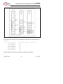
1
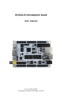
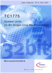
Application Note, V 2.1, Sept. 2002
AP32029
TC1775
Pe ak & H old Curr en t Shape
g ene ra te d by TriC ore der iva tive
TC17 75
Micr ocon tr ollers
N e v e r
s t o p
t h i n k i n g .
TC1775
Revision History:
2002-09
Previous Version:
V2.0, 2001-09
Page
Subjects (major changes since last revision)
All
Adjusted to conform with Infineon template
several PCP functionality included
2.1
Controller Area Network (CAN): Licence of Robert Bosch GmbH
We Listen to Your Comments
Any information within this document that you feel is wrong, unclear or missing at all?
Your feedback will help us to continuously improve the quality of this document.
Please send your proposal (including a reference to this document) to:
[email protected]
AP32029
Peak & Hold Current Shape generated by TriCore
Introduction
Table of Contents
Page
1
Introduction.................................................................................................... 4
2
2.1
2.2
2.2.1
2.2.2.1
2.2.2.2
2.2.2.3
System Requirements for Direct Injection Applications ................................. 5
System Overview........................................................................................... 5
Possible System Solutions ............................................................................ 7
Generation of Peak&Hold Current Shape with Application Specific IC
(ASIC).................................................................................................... 8
Generation of Peak&Hold Current Shape with GPTA Peripheral
Module................................................................................................. 10
Parallel High Side Switch Configuration ........................................... 10
Serial High Side Switch Configuration .............................................. 11
Low Side Switch Current PWM ........................................................ 12
3
3.1
3.2
3.3
Closed Loop Current Control together with GPTA....................................... 13
Usage of Global Timer Cell Array ................................................................ 15
Usage of Local Timer Cell Array.................................................................. 17
Overview about the complete generated Waveforms .................................. 19
4
4.1
4.1.1
4.1.2
4.1.2.1
4.1.2.2
4.1.2.3
4.1.2.4
4.1.3
System Partitioning...................................................................................... 22
The Peripheral Control Processor (PCP)..................................................... 22
PCP Initialization ................................................................................. 23
The PCP Program File......................................................................... 23
PCP Sections ................................................................................... 24
Start Address of a Channel Program................................................ 24
PCP Context..................................................................................... 25
Variables and Constants in PCP Parameter RAM............................ 27
PCP Debugging and Test .................................................................... 28
5
5.1
5.2
5.3
Software Application Example ..................................................................... 29
Overview of configurable Parameters.......................................................... 30
Used GPTA Resources for the Peak&Hold Generation............................... 32
Connection to PC Terminal Program........................................................... 33
6
Conclusion................................................................................................... 34
7
7.1
7.2
7.3
7.4
Appendix...................................................................................................... 35
Related Documentation and SW Package .................................................. 35
List of Figures .............................................................................................. 35
List of Tables ............................................................................................... 35
Abbreviations............................................................................................... 36
2.2.2
Application Note
3
2.1, 2002-09
AP32029
Peak & Hold Current Shape generated by TriCore
Introduction
1
Introduction
The following application note deals with the generation of a Peak&Hold Current
Shape which becomes more and more popular in automotive application areas.
Especially in Powertrain applications like Direct Gasoline or Diesel Common Rail
Direct Injection Combustion Engines, the Peak&Hold Current Shape is widely spread
to drive the coils of conventional high pressure injectors.
In future Application Segments like Electronic Valve Control (EVT) systems, the
generation of a flexible Peak&Hold current waveforms together with high voltage
usage will be also a key success factor for precise electronic controlling of the valves.
Figure 1 outlines a typical Peak&Hold Current Waveform for an high pressure injector:
I
Peak_Threshold
Injector Current
Hold_Threshold
T1 ... Peak
T2 ... Hold
t
Figure 1
Peak&Hold Current Shape
During ´Peak_Time´ T1, a high voltage (approx. 80V) is applied to the injector coil and
the current level is controlled at current level ´Peak_Threshold´.
During ´Hold_Time´ T2, the normal automotive board voltage (12V) is applied to the
injector coil and the current level is controlled at current level ´Hold_Threshold´.
Main part of this application note will be the detailed description of the generation of a
Peak&Hold Current Shape together with a closed loop current control algorithm by
using the TriCore derivative TC1775. This algorithm and the corresponding control
signals are generated by using the embedded General Purpose Timer Array (GPTA)
peripheral within the TC1775 controlled either by the CPU or Peripheral Control
Processor (PCP).
Application Note
4
2.1, 2002-09
AP32029
Peak & Hold Current Shape generated by TriCore
System Requirements for Direct Injection Applications
2
System Requirements for Direct Injection Applications
The following chapter gives a basic introduction into a state of the art high pressure
diesel direct injection system with coil driven injectors. Further different approaches to
fulfill the direct injection requirements will be discussed.
2.1
System Overview
The electronic circuit of a state of the art implementation consists of the following parts:
•
•
•
•
•
High voltage (80V) for a fast injector response time
Battery voltage used for the hold current of the valve
Current measurement achieved by using a shunt resistor
Current control with two high side switches; peak current controlled by HSS2, hold
current controlled by HSS1
Cylinder selection achieved with low side switches
VBB
Shunt for Diagnosis
Ubatt HSS1
55 V
Injector
Vz ≈
10-60 V
Freewheeling
Path
V80
Booster
HSS2 100 V
Injector
BoosterCapacitor
LS 2
100 V
LS 1
100V
Shunt for Current Control
Figure 2
Peak&Hold Electronic Circuit - Block Diagram
In this parallel highside switch configuration, the Peak&Hold current regulation has to
be performed by controlling HSS2 switch with a PWM for the ´Peak_Time´ and HSS1
by a PWM for the Hold_Time.
As a representative for a state of the art common rail diesel direct injection system, a
coil driven current controlled injector can be found in Figure 3 below:
Application Note
5
2.1, 2002-09
AP32029
Peak & Hold Current Shape generated by TriCore
System Requirements for Direct Injection Applications
Technical Parameters:
Figure 3
•
Pressure up to 1350 bar
•
Five nozzles of 0.12mm each
•
quantities down to 1mm as minimum dosage
•
coil impedance < 0.4 Ω
3
Coil driven current controlled high pressure Injector
Application Note
6
2.1, 2002-09
AP32029
Peak & Hold Current Shape generated by TriCore
System Requirements for Direct Injection Applications
2.2
Possible System Solutions
The implementation for generating a Peak&Hold current shape can be solved by using
different system solution configurations.
In principle the following descriptions presents two different system solutions:
1.
All necessary current control algorithms are implemented in a Peak&Hold
Application Specific Integrated Circuit (ASIC)
2.
An intelligent peripheral module, the General Purpose Timer Array (GPTA) of the
TriCore Microcontroller TC1775 is used for the control algorithm and the diagnosis
of a Peak&Hold coil driven current controlled injector.
This application note mainly focuses to the second approach:
The generation of the Peak&Hold current waveform together with the TC1775.
Application Note
7
2.1, 2002-09
AP32029
Peak & Hold Current Shape generated by TriCore
System Requirements for Direct Injection Applications
2.2.1
Generation of Peak&Hold Current Shape with Application
Specific IC (ASIC)
One of the possible system solutions is to use an external ASIC to control the
Peak&Hold current shape. A Quad Direct Injection Switch is intended to be used for
the generation of Peak&Hold current shapes for direct injection applications.
Figure 4 shows a possible partitioning for a Peak&Hold direct injection system solution
together with an ASIC:
SPB47N10L
VBB
60..80 V
DC/DC
Converter
VBB
HS 2 / EN_80
HS 1 / EN_12
HS 1 HS 2
TLE4470
KP
120
LS 1
LS 2
Current
Control
14A
Logic
Protection
SPI
Interface
TLE4250
C505CA
High Side
Control
TLE6240
BUZ 111S
BUZ 110 SL
HS1: 60-100 mΩ
Ω / 50 V
HS2: 40-100 mΩ
Ω / 100 V
LS1: 100-150 mΩ
Ω / 90 V
LS2: 100-150mΩ
Ω / 90 V
Engine
control
unit
BAS 70
TLE6250
4A
Bank 1
C167CS/
TRICORE
Bank 2
Figure 4
Direct Injector Drive for Peak&Hold together with ASIC
The usage of an ASIC summarizes the following benefits and features:
- Reduction of external components (Diodes/Shunt)
- Fully protection against overvoltage, overload, short circuit, overtemperature, ESD
- Automatical Current Shaping
- Full Diagnosis and Configuration via SPI interface
- Current matching between the channels
- Peak&Hold current adjustable (for different engines)
- Increase of system reliability
- Decrease of system costs
Application Note
8
2.1, 2002-09
AP32029
Peak & Hold Current Shape generated by TriCore
System Requirements for Direct Injection Applications
Figure 5 shows a possible waveform for the Peak&Hold current shape generation by
using an ASIC. The length of the peak time (t1) and the off-time (t2) can be configured
externally by using the SPI interface:
t1
t2
Injector
Current
EN_80
Note:
t1/t2 are
programmable
via SPI/SSC
EN_12
Injector
Pulse
Figure 5
Possible generated Waveform for the usage of an ASIC
Application Note
9
2.1, 2002-09
AP32029
Peak & Hold Current Shape generated by TriCore
System Requirements for Direct Injection Applications
2.2.2
Generation of Peak&Hold Current Shape with GPTA Peripheral
Module
A complete different way for the generation of the Peak&Hold current shape is the
usage of the 32-bit TriCore derivative TC1775. All used control signals can be easily
generated by using the embedded peripheral module GPTA.
In the following chapter, there will be given an overview of three different circuit
configurations, which could be used in principle to realize a direct injection Peak&Hold
application.
2.2.2.1
Parallel High Side Switch Configuration
Vboost = 80V
Vb = 12V
HS_Switch_1 / EN_12
HS_Switch_2 / EN_80
AUDO / TC1775
(TriCore)
HS_Switch_5 /AFWH
HS_Switch_1 / EN_12
HS_Switch_2 / EN_80
Injector
CYL_1
Injector
CYL_2
Injector
CYL_3
Injector
CYL_4
LS_Switch_1
(CYL_SEL_1)
LS_Switch_2
(CYL_SEL_2)
LS_Switch_3
(CYL_SEL_3)
LS_Switch_4
(CYL_SEL_4)
CYL_SEL_1
CYL_SEL_2
GPTA
CYL_SEL_3
CYL_SEL_4
+
-
SCOUT
-
+
SWTL
CYL_SEL_x
Shunt
Note: Free Wheeling can be
achieved by optional
Diodes
0/5V
Threshold
Value
Figure 6
Block Diagram 1 for Parallel High Side Switch Configuration
Both high side switches are used to drive the PWM current through the coil of a
selected injector.
Optional free wheeling diodes can be used dependant on the decay time of the
inductance.
Application Note
10
2.1, 2002-09
AP32029
Peak & Hold Current Shape generated by TriCore
System Requirements for Direct Injection Applications
The current is monitored with a shunt resistor. An external comperator evaluates the
occuring voltage on the resistor. The measured value is compared to a given
programmable threshold (either peak value or hold value). The GPTA module is used
to capture the signal SCOUT at the output of the comperator.
2.2.2.2
Serial High Side Switch Configuration
Vboost = 80V
HS_Switch_2 / EN_80
Vb = 12V
HS_Switch_1 / EN_12
AUDO / TC1775
(TriCore)
HS_Switch_5 /AFWH
HS_Switch_1 / EN_12
HS_Switch_2 / EN_80
Injector
CYL_1
Injector
CYL_2
Injector
CYL_3
Injector
CYL_4
LS_Switch_1
(CYL_SEL_1)
LS_Switch_2
(CYL_SEL_2)
LS_Switch_3
(CYL_SEL_3)
LS_Switch_4
(CYL_SEL_4)
CYL_SEL_1
CYL_SEL_2
GPTA
CYL_SEL_3
CYL_SEL_4
+
-
SCOUT
-
+
SWTL
Shunt
CYL_SEL_x
Note: Free Wheeling can be
achieved by optional
Diodes
0/5V
Threshold
Value
Block Diagram for Peak- and Hold Injection
Demonstrator for Diesel Common Rail
Topologie 1
Figure 7
Block Diagram 2 for Serial High Side Switch Configuration
In the configuration shown in Figure 7, two serial high side switches are used to
generate the Peak&Hold current waveform applied to the coil of a selected injector.
The difference to the previous parallel high side switch configuration is, that the current
control loop can be achieved by using only one high side switch EN_12 for the PWM.
The high side switch EN_80 is only switched on at the beginning of the ´Peak_Time´
and switched off at the end of the Peak_Time.
Optional free wheeling diodes can be used dependant on the decay time of the
inductance.
The current feedback is done like in the previous configuration in block diagram 1.
Application Note
11
2.1, 2002-09
AP32029
Peak & Hold Current Shape generated by TriCore
System Requirements for Direct Injection Applications
2.2.2.3
Low Side Switch Current PWM
Vboost = 80V
HS_Switch / EN_80
AUDO1 / TC1775
(TriCore)
Vb = 12V
HS_Switch / EN_80
EN_LOW
CYL_SEL_1
&
CYL_SEL_2
&
CYL_SEL_3
&
CYL_SEL_4
&
GPTA
LS_Switch_1
LS_Switch_2
LS_Switch_3
Injector
CYL_4
LS_Switch_1
(CYL_SEL_1
& EN_LOW)
LS_Switch_2
(CYL_SEL_2
& EN_LOW)
LS_Switch_3
(CYL_SEL_3
& EN_LOW)
LS_Switch_4
(CYL_SEL_4
& EN_LOW)
-
Shunt
CYL_SEL_x
0/5V
Threshold
Value
Figure 8
Injector
CYL_3
+
+
SWTL
Injector
CYL_2
LS_Switch_4
-
SCOUT
Injector
CYL_1
Note: Free Wheeling is
achieved by Zener
Clamping applied to the
Low Side Switches
Block Diagram 3 for Low Side Switch Current PWM
Only one high side switch (see Figure 8) is used to select the high voltage for the
´Peak_Time´ of the Peak&Hold current shape. The low side switch is used both for the
selection of the cylinder and for switching the current PWM. This configuration affords
some small additional glue logic (logical AND) for the signals CYL_SEL_x and the
current control signal EN_LOW.
Free wheeling is achieved by zener clamping applied to the low side switches. This
results in a fast decay of the free wheeling current.
This method cannot be applied directly to the configurations of block diagrams 1 and 2,
because the high side switches needs a more complex controlling of their gates. When
the high side switches in block diagrams 1 and 2 are switched off without using a free
wheeling circuit, the source of the high side switches gets negative because of the
inductivity from the coil and the switches itself into avalanche condition.
This affords some additional HW effort. Therefore, the given application SW and the
build up demonstrator bases on the third system solution:
The PWM based low side switch current generation as shown in Figure 8.
Application Note
12
2.1, 2002-09
AP32029
Peak & Hold Current Shape generated by TriCore
Closed Loop Current Control together with GPTA
3
Closed Loop Current Control together with GPTA
In the following chapter the General Purpose Timer Array (GPTA) within the TC1775
device is introduced. Further a detailed explanation how to generate the corresponding
control signals by using the Global Timer Cell Array (GTCA) and the Local Timer Cell
Array (LTCA) is given.
General Overview:
FPC 00
DCM 00
FPC 01
PDL 00
DCM 01
FPC 02
FPC 03
DIGITAL
PLL
DCM 02
FPC 04
PDL 01
DCM 03
FPC 05
fGPTA
Clock Distribution
Unit
Clock Generation Unit
Signal Generation Unit
GT 0
GT 1
LTC 00
GTC 01
LTC 01
GTC 02
LTC 02
GTC 03
GTC 04
Figure 9
Clock Bus
GTC 00
LTC 03
LTC 04
Global Timer
Cell Array
Local Timer
Cell Array
GTC 30
LTC 62
GTC 31
LTC 63
Block Diagram of GPTA peripheral
The GPTA unit consists of the following Sub-Modules:
Clock Generation Unit:
FPC Filter and Prescaler Cell
PDL Phase Discrimination Logic
DCM Duty cycle Measurement Cell
PLL Phase Locked Loop
Signal Generation Unit:
GTx Global Timer 0 and 1
GTC Global Timer Cell
LTC Local timer Cell
Application Note
13
2.1, 2002-09
AP32029
Peak & Hold Current Shape generated by TriCore
Closed Loop Current Control together with GPTA
The GPTA Module is intended to be used for the following signal preconditioning,
counting, capture, compare and PWM functionalities:
-
Flexible Clock Generation, filtering and high resolution signal acquisition
Digital PLL
Universal Building Blocks can be combined to form the required timer structure
("LEGO" approach)
Global Timer Cell Array (32 cells, 24-bit wide GTC) operates relative to global
timers array - mainly used for input signal capturing and output signal generation
Local Timer Cell Array (64 cells, 16-bit wide LTC) will operate relative to local
timers - mainly used for PWM signal generation and input signal measurement
32 + 8 KB DSRAM
INT
FPI Bus
Peripheral
Control
Processor
Figure 10
SSC1
PORTS
SSC0
ASC1
ASC0
J1850
TwinCAN
GPTA
GPTU
ADC 1
ADC 0
Real Time
Clock (RTC)
PLL
System
Control Unit
(SCU)
System Timer
Debug
Module
Ext.. Bus
Interf.(EBUA)
INT
Lay er
4 KB Parameter DSRAM
P hys ic al
16KB Code CSRAM
L aye r
32KB
Scratch Pad CSRAM
A pp lication
The GPTA needs to be reconfigured for some application tasks. To avoid bottlenecks
in real time behaviour, there has been implemented an interrupt driven Peripheral
Control Processor (PCP) to the TC1775. The PCP is intended to be used for driving
the peripheral set of the TC1775. The PCP could be used for instance for signal
preconditioning and provide the filtered sensor input data to the application SW via a
standardized API (Application Programmers Interface). Therefore a clear separation
between the application layer and the physical layer within the embedded application
can be achieved.
TC1775 – System Partitioning
The PCP executes its assembly instructions out of its own memory resources (16 KB
Code SRAM and 4 KB Data SRAM), and shares the 32-bit wide Flexible Peripheral
Interconnection (FPI) bus together with the TriCore CPU. This high speed 32-bit FPI
bus connects all internal peripheral and system modules and all internal/external
memory portions within this multiprocessor architecture.
Application Note
14
2.1, 2002-09
AP32029
Peak & Hold Current Shape generated by TriCore
Closed Loop Current Control together with GPTA
3.1
Usage of Global Timer Cell Array
The Global Timer Cell Array basically is used to generate all signal outputs needed for
the Peak&Hold frame signals. The current control algorithm itself is performed by the
Local Timer Cell Array. The generated frame signals for the Peak&Hold current
waveform are for instance the selection of the injector or the length of the injector
pulse itself.
Two informations are mandatory for a typical engine management system controlling a
combustion motor:
1.
An angle based timer information (angle domain), which represents the exact
position of the crankshaft and the camshaft of the engine.
2.
A time based timer information (time domain), where all relevant signal lengthes
can be derived from.
These two basic timer informations are mapped within the GPTA module in HW to the
24-bit wide global timers GT0 and GT1.
The customers application SW calculates an engine position based start angle for the
determination of the start of the injection pulse of a single injector for one cylinder. The
begin of injection pulse has to be mapped into the time domain and the corresponding
injection pulse length has to be calculated.Fehler! Verweisquelle konnte nicht
gefunden werden.Figure 11 shows the dependency between the angle domain and
the time domain:
Global Timers
Angle
Time
Global Timer Cells
Injector pulse for Cylinder 1
Compare, Capture
Compare, Capture
Injector pulse for Cylinder 2
Compare, Capture
Injector pulse for Cylinder 3
Compare, Capture
Injector pulse for Cylinder 4
Figure 11
Realization of Injector Pulse together with GT0/1 and GTCs
Application Note
15
2.1, 2002-09
AP32029
Peak & Hold Current Shape generated by TriCore
Closed Loop Current Control together with GPTA
This application note mainly focuses on the generation of the Peak&Hold control
signals within the time domain. Therefore the delivered SW demonstrator example only
uses GT0 (mapped to the time domain) as a free running timer.
Taking advantage of the flexible timer structure of GPTA module, it is sufficient to
allocate one separate GTC for each Injector (each cylinder of the engine).
Additionally two further control signals EN_80 (Enable 80V) and SWTL (Switch
Threshold) has to be generated. EN_80 determines the length of the high voltage
switch on time (Peak_Time) and SWTL is used to switch between the externally used
comparison current level thresholds (for instance 12A for the ´Peak_Time´ and 5A for
the Hold_Time). Each of these signals need only one GT cell and can be used for all
four cylinders of the combustion engine, when no overlapping phases between the
injection pulses are required. Otherwise two more GT cells for the generation of the
signals EN_80 and SWTL has to be allocated.
Peak_Threshold
Injector Current
Hold_Threshold
T1 ... Peak
T2 ... Hold
Global Timer
Time Domain
Global Timer Cells
Capture/Compare
(CYL_SEL_x)
CYL_SEL_x
SWTL
EN_80
Compare (SWTL)
Compare (EN_80)
Global Timer
(free running)
Figure 12
Injection Pulse Generation with GT/GTC
Application Note
16
2.1, 2002-09
AP32029
Peak & Hold Current Shape generated by TriCore
Closed Loop Current Control together with GPTA
The generation of the basic control signals CYL_SEL_x / SWTL and EN_80 can be
achieved by the following configuration scheme:
The customers application SW generates a rising edge (begin of injection pulse) of the
CYL_SEL_x output signal and simultaneously an interrupt is generated, which is
executed by using the PCP or CPU. This interrupt routine reconfigures the GT cells for
the signals CYL_SEL_x, SWTL and EN_80 as follows:
-
CYL_SEL_x GT cell is reconfigured to the new compare value ´end of injection
pulse´.
-
SWTL is reconfigured to switch the threshold level from peak current to hold
current after the ´Peak_Time´ has expired and simultaneously an interrupt will be
generated when the rising edge of SWTL occurs. This second interrupt
reconfigures the SWTL GT cell to the ´end of injection pulse´.
-
EN_80 GT cell is reconfigured to the length of ´Peak_Time´ .
3.2
Usage of Local Timer Cell Array
The closed loop algorithm for controlling the peak and hold currents for the Peak&Hold
current shape is managed by using a four cell Local Timer Cell Array (LTC) model.
Captured Value
(can be used for
Diagnosis)
Reset_Timer_1
Local Timer Cells
Reset_Timer_1
Capture_1 (EN_LOW_OFF)
Reset
timer
SCOUT_INPUT
Compare_1
(EN_LOW_OFF_TIME)
Compare_2
(EN_LOW_MAX_ON_TIME)
Figure 13
(EN_LOW_MAX_OFF_TIME)
(EN_LOW_
OFF_TIME)
Threshold
Injector Current
SCOUT
EN_LOW_Output
EN_LOW
Current Control by using a 4-Cell LTC Model
This 4-cell LTC model consists of one injector current feedback input signal SCOUT
(external current sense compare input), which generates a falling edge each time, the
current rises above a predefined threshold value. It also supports one output signal
EN_LOW, which generates the control PWM for the current through the injector. The
model is driven by a ´Reset_Timer_1´ LT cell and controls the injectors current
autonomously without consuming any CPU/PCP load.
Application Note
17
2.1, 2002-09
AP32029
Peak & Hold Current Shape generated by TriCore
Closed Loop Current Control together with GPTA
The completely HW based control mechanism works as follows:
A falling edge on input signal SCOUT generates simultaneously the below described
HW driven actions:
-
The actual 16-bit timer value of ´Reset_Timer_1´ is stored to SFR LTCxR and can
be used for diagnosis purposes.
-
The ´Reset_Timer_1´ will be cleared to zero and restarted.
-
The EN_LOW output gets a falling edge and therefore switches off the current
Due to the reseted and restarted timer, the current through the injector will remain
switched off until the ´Reset_Timer_1´ matches with LT cell ´Compare1´ with the
preprogrammed value EN_LOW_OFF_TIME.
This event generates a rising edge on output signal EN_LOW and therefore again
enables the current through the coil.
The signal EN_LOW remains switched on until the coils current again rises above the
predefined threshold and therefore generates a new capture event in LTC cell
´Capture_1´.
This mechanism is operable only, if the measured current sense feedback input signal
SCOUT reacts fast enough without having a to big hysteresis.
An additional LT cell ´Compare_2´ is used to limit the maximum switch on time for the
current through the coil to EN_LOW_MAX_ON_TIME. The LTC ´Compare_2´ cell is
needed for safety reasons to avoid any damage to the injectors coil if for instance the
current sense feedback signal SCOUT is broken.
Application Note
18
2.1, 2002-09
AP32029
Peak & Hold Current Shape generated by TriCore
Closed Loop Current Control together with GPTA
3.3
Overview about the complete generated Waveforms
(Stop_Timer_1)
(INT-Delay)
4
(INT-Delay)
3
Reset_Timer_1
SCOUT
EN_LOW
EN_80
CYL_SEL_x
SWTL
1
(INT-Delay)
2
(EN_LOW_
OFF_TIME)
Injector Current
Peak_Threshold
I
Figure 14
(INT-Delay)
(INT-Delay)
5
Hold_Threshold
IP / CYL_SELx
SWTL
EN_80
EN_LOW
SCOUT
... Injector Pulse / Cylinder Select (x = 1-4)
... Switch Threshold Level
... Output of High-Side-Switch for 80V
... Output of Low-Side-Switch for PWM
... external Sense Comperator Input
... Event generates Interrupt
t
This chapter deals with a short summary of all the control signals generated by the
GPTA module and it also shows a measured Peak&Hold current waveform coming out
of the build up demonstrator:
Complete Control Signals generated by the GPTA peripheral
Application Note
19
2.1, 2002-09
AP32029
Peak & Hold Current Shape generated by TriCore
Closed Loop Current Control together with GPTA
Figure 14 summarizes all relevant interrupt based reconfigure interactions, which have
to be executed by using the TriCore CPU or the Peripheral Control Processor (PCP).
1st Interrupt generated at the beginning of the Injection Pulse (rising edge of
CYL_SEL_x):
-
CYL_SEL_x pulse length is configured
SWTL signal is configured to ´Peak_Time´ and interrupt action is prepared when
rising edge occurs
EN_80 signal is configured to ´Peak_Time´ length
EN_LOW signal is switched on
Interrupt action prepared if first falling edge is detected at input SCOUT
2nd Interrupt generated at the first falling edge of input signal SCOUT:
-
EN_LOW switched off simultaneously switched off with falling edge of SCOUT
(HW)
4-cell LTC current control model configured for autonomous work
Reset and Start ´Reset_Timer_1´
3rd Interrupt generated with rising edge of signal SWTL:
-
SWTL ´Hold_Time´ length configured
EN_LOW signal switched off
Interrupt action prepared if rising edge occurs at signal SCOUT
4th Interrupt generated with rising edge of signal SCOUT:
-
EN_LOW switched on
4-cell LTC current control model configured for autonomous work
´Reset_Timer_1´ reseted and restarted
5th Interrupt generated at the end of the injection pulse (falling edge of CYC_SEL_x):
-
EN_LOW switched off
´Reset_Timer_1´ switched off
Application Note
20
2.1, 2002-09
AP32029
Peak & Hold Current Shape generated by TriCore
Closed Loop Current Control together with GPTA
In the following Figure 15 the measured Peak&Hold current shape by using the
delivered application SW for this application note can be found:
EN_80
SCOUT
2b
1 2
Interrupt
Activity
4b/c
34
5
Injector
Current
Figure 15
Measured Waveform for Generation of Peak&Hold Current Shape
In contrary to the description of Figure 14 three more interrupts than described (2b and
4b/c) are generated. These interrupts have been added to the Peak&Hold application
SW example for diagnosis purposes.
The peak current in this example is about 13A and the hold current about 5A.
The approximate CPU/PCP load in this example is about 2% for a injector pulse length
of 900 µs.
Application Note
21
2.1, 2002-09
AP32029
Peak & Hold Current Shape generated by TriCore
System Partitioning
4
System Partitioning
This application offers the possibility to use either the CPU or PCP to control the
current shape generation. When the PCP is used the CPU is not needed at runtime to
control the GPTA. The startup initialization of the GPTA is always done by the CPU
because it makes no sense to do this with the PCP. For that a copy of the PCP
initialization program would have to be held in the CPU memory, copied to PCP Code
RAM and than executed. It's faster to do this by the CPU, even less (PCP) memory
has to be used.
At runtime the current shape generation is completely controlled with three interrupts.
This interrupts has to be mapped either to the CPU or PCP.
4.1
The Peripheral Control Processor (PCP)
As already described in chapter 3 the PCP has its own Code and Data RAM. This
chapter gives some hints how the PCP has to be handled.
Figure 16
PCP Block Diagram
Additional information can be found in the User's Manual and in the application note
AP3225 "The Peripheral Control Processor (PCP) or a smart way to service an
interrupt request".
Application Note
22
2.1, 2002-09
AP32029
Peak & Hold Current Shape generated by TriCore
System Partitioning
4.1.1
PCP Initialization
The PCP has first to be initialized before program code can be executed. This
initialization can also be done using DAvE, the "Digital Application Engineer" available
from Infineon.
Mainly the two registers "PCP Control/ Status Register" (PCP_CS) and "PCP Interrupt
Control Register (PCP_ICR)" has to be initialized what is done in the "main.c".
The PCP can be used in different modes and with different context sizes. In this
application the channel resume mode and full context (8 registers for each channel) is
chosen. In channel resume mode, the user can arbitrarily determine the address at
which the channel program will be started the next time it is invoked. For this purpose,
the PC is saved and restored as part of the context of a PCP channel.
The interrupts call a particular part of the PCP program, a so called PCP channel. The
interrupt priority corresponds to the channel number. So an interrupt with priority 7
would call the PCP channel 7 if it is mapped to the PCP.
In the "Service Control Register" it can be determined by the bitfield "TOS" if the
service is be done either by the CPU or PCP.
mod_SRC
Service Request Control Register
31
30
29
28
27
26
Reset Value: 0000 0000H
25
24
23
22
21
20
19
18
17
16
7
6
5
4
3
2
1
0
0
r
15
14
13
12
SET CLR SRR SRE
R
R
w
4.1.2
w
rh
rw
11
10
9
8
TOS
0
SRPN
rw
r
r
The PCP Program File
The PCP has its own instruction set so a special assembler is necessary. In the
Tasking toolchain the PCP compiler "ASPCP" is integrated which allows to handle the
PCP file with the EDE.
This PCP file has to follow a certain structure so that it can be assembled.
Application Note
23
2.1, 2002-09
AP32029
Peak & Hold Current Shape generated by TriCore
System Partitioning
4.1.2.1
PCP Sections
The PCP file has to contain the sections CODE and DATA which correspond to the
PCP Code memory (program) respectively to the PCP Parameter memory (context
and data). Following an example for the CODE and DATA section definition:
;------------------------------------------------------------------; Sections Definitions
; PRAM Code definition, starting at address 0x02
;------------------------------------------------------------------.SDECL "pcp.code", CODE, INIT AT 0x2 ;PCP Rom memory, PCODE
.SECT "pcp.code"
;Write into PCP Code Section
;------------------------------------------------------------------; PRAM context definition, starting at address 0x00
;------------------------------------------------------------------.SDECL "pcp.context", DATA, INIT AT 0x0 ;PCP Ram memory, PRAM
.SECT "pcp.context"
;Write into PCP RAM Section
When using the PCP without a debugger, please assure that a copy of the Parameter
RAM (PRAM) and the Code RAM (PCODE) of the PCP is done in the ROM area.
During the "cstart.asm" execution, these memory portions will be copied automatically
into the corresponding PCP memory SRAM locations after power on reset.
For the Tasking Tricore Toolchain, this can be achived by the keyword INIT beginning
with V1.1R2.
4.1.2.2
Start Address of a Channel Program
As mentioned above in channel resume mode the start address for a certain PCP
channel is determined by the PC (Program Counter) which is stored in the context.
This PC is updated when the channel is left. But when the channel is called for the first
time the PC is not automatically set. It is possible to initialize the register R7 in the
context with the start address of the corresponding channel, but this has the
disadvantages that it has to be calculated by the user and it has to be updated every
time when a modification in the code is done which leads to another start address of
the channel.
For this reason a channel entry table is used for the first call of the channels. This
channel entry table is located at the beginning of the PCP Code RAM and contains a
jump to the corresponding channel whereby a label can be used. The PC in the
Application Note
24
2.1, 2002-09
AP32029
Peak & Hold Current Shape generated by TriCore
System Partitioning
context of each channel points to the corresponding jump instruction and the target
address will be calculated by the assembler.
;------------------------------------------------------------------; Channel Entry Point Table
;------------------------------------------------------------------;initial start of Channel 1 (SRPN 1)
CH1: JC.A CH1A, cc_UC
;jump to start of channel 1
;initial start of Channel 2 (SRPN 2)
CH2: JC.A CH2A, cc_UC
;jump to start of channel 2
.
.
.
CH1A:
....
.
.
.
CH2A:
....
.
.
.
4.1.2.3
PCP Context
Each channel has its own context which consists of eight 32-bit registers. Depending
on the context model two (minimum context), four (small context) or eight (full context)
of these registers are automatically saved/ restored at channel start/ exit. In this
application the full context model is used.
The contexts of the different channels is stored in the PRAM.
Application Note
25
2.1, 2002-09
AP32029
Peak & Hold Current Shape generated by TriCore
System Partitioning
Figure 17
Context Storage in PRAM
The context of the channels has to be initialized in the section DATA at address 0x00:
.space 32
Ch1:
.word
.word
.word
.word
.word
.word
.word
.word
0x00020340
0x00000000
0x00000000
0x00000000
0x00000000
0x00000000
0x00000000
0x00000000
;R7 channel enable set, DPTR=3, PC = 2
;R6
;R5
;R4
;R3
;R2
;R1
;R0
Channel 0 mustn't be used so no context for this channel is necessary.
Application Note
26
2.1, 2002-09
AP32029
Peak & Hold Current Shape generated by TriCore
System Partitioning
4.1.2.4
Variables and Constants in PCP Parameter RAM
The PCP Parameter RAM (PRAM) at local address zero (0) is always implicitly used
for the context save areas of the channel programs, the remaining area can be used
for channel-specific or general data storage. A programmable 8-bit data pointer
(DPTR), concatenated with a 6-bit offset, is provided for arbitrary access to the PRAM.
Every channel has its own data pointer DPTR, which is very much like a segment
register. It is located in register R7 and has to be initialized accordingly. This DPTR
points to a 64-word base address which has to be higher then the last channel context.
It is recommended to define an extra section for the data.
;------------------------------------------------------------------; PRAM data definition, starting at address 0x80 (PRAM Datapage 2)
;------------------------------------------------------------------.SDECL "pcp.data", DATA, INIT AT 0x080
.SECT "pcp.data"
pEN_LOW_ON_MAX_HOLD:
pEN_LOW_OFF_HOLD:
pSCOUT_PERIOD_2:
;PCP Ram memory, PRAM
;Write into PCP RAM Section
.word EN_LOW_ON_MAX_HOLD
.word EN_LOW_OFF_HOLD
.word SCOUT_PERIOD_2
It is necessary to declare the constants and variables defined in the C-files with the
".extern" directive so the assembler can access them:
;------------------------------------------------------------------; External Symbol Declaration
;------------------------------------------------------------------.extern EN_LOW_ON_MAX_HOLD
.extern EN_LOW_OFF_HOLD
.extern SCOUT_PERIOD_2
;to pass addresses of constants
.extern
.extern
.extern
.extern
;to pass addresses of variables
pulse_level_cyl_1
diagnosis_hold
diagnosis_peak
begin_injection
Note: The prefix _PCP_ for global symbols is not used in this project. The Tasking
EDE uses this prefix on default; it can be modified in EDE\ PCP Assembler
Options\ Project Options\ Misc.
Application Note
27
2.1, 2002-09
AP32029
Peak & Hold Current Shape generated by TriCore
System Partitioning
4.1.3
PCP Debugging and Test
To debug the PCP some requirements have to be observed like full context has to be
used or a PCP error interrupt routine has to be available. Because this requirements
depends mainly on the used tools please refer to the according tools manual.
Application Note
28
2.1, 2002-09
AP32029
Peak & Hold Current Shape generated by TriCore
Software Application Example
5
Software Application Example
The delivered SW package can be used to build up a functional demonstrator driving
real HW by using block diagram 3 from Figure 8.
Additionally the demonstrator SW can be taken to generate the simulated control
waveforms by using a simulated SCOUT signal.
This simulated SCOUT signal is generated by using extra Local Timer (LTC 27-30)
within the GPTA. The output of the simulated SCOUT signal has to be connected
externally to the 4-cell local timer current control model.
In the following Figure 18 the simulated Peak&Hold injector PWM can be found:
EN_80
SCOUT
simulated
Interrupt
Activity
Injector
PWM
Figure 18
Simulated Waveform for Generation of Peak&Hold Current Shape
This SW-demonstrator example was developed by using the TriCore Tasking
Toolchain V1.1R2/ V1.3R1 and the evaluation PCB TriBoard for TC1775.
Application Note
29
2.1, 2002-09
AP32029
Peak & Hold Current Shape generated by TriCore
Software Application Example
5.1
Overview of configurable Parameters
In the following paragraph the constant definitions for the generation of the Peak&Hold
waveform can be found in the SW package located in file GPTA.C:
- The initialization of the injection frame signals CYL_SELx, SWTL and EN_80:
#define
#define
#define
#define
INJ_PULSE_ms
IDLE_LENGTH_ms
SWTL_LENGTH_us
EN_80_LENGTH_us
0.9
400
300
300
//
//
//
//
high level length of CYL_SEL_x
low level length of CYL_SEL_x
low level lenghth of SWTL
low level lenghth of EN_80
- The initialization of the closed loop Peak&Hold current algorithm:
#define EN_LOW_ON_MAX_PEAK_FIRST_us
60
// time, inbetween low side switch EN_LOW is switched on in maximum at
// beginning of the injection
#define EN_LOW_ON_MAX_PEAK_us
20
// time, inbetween Peak phase where low side switch EN_LOW is switched
// on in maximum (should be bigger than period of SCOUT)
#define EN_LOW_ON_MAX_HOLD_us 30
// time, inbetween HOLD phase where low side switch EN_LOW is switched
// on in maximum (should be bigger than period of SCOUT)
#define EN_LOW_OFF_PEAK_us
9
#define EN_LOW_OFF_HOLD_us
4
Application Note
//
//
//
//
time, inbetween low
switched off during
time, inbetween low
switched off during
30
side
PEAK
side
HOLD
switch is
phase
switch is
phase
2.1, 2002-09
AP32029
Peak & Hold Current Shape generated by TriCore
Software Application Example
- the initialization for the simulated SCOUT output generated by LT cells 27-30:
//---------------------------------------------------------------------// This part serves as threshold input stimuli generation
//---------------------------------------------------------------------// valid beginning with injection pulse
#define SCOUT_PERIOD_1_us
12
// period 1 of input stimuli SCOUT
// valid beginning with falling edge of EN_80
#define SCOUT_PERIOD_2_us
50
// period 2 of input stimuli SCOUT
#define SCOUT_LOW_EDGE_1_us
4
#define SCOUT_HIGH_EDGE_1_us
6
//
//
//
//
falling edge of input stimuli SCOUT
within PERIOD1 of SCOUT
rising edge of input stimuli SCOUT
within PERIOD1 of SCOUT
// valid beginning with falling edge of EN_80
#define SCOUT_LOW_EDGE_2_us
0
// falling edge of input stimuli SCOUT
// within PERIOD2 of SCOUT
#define SCOUT_HIGH_EDGE_2_us
25
// rising edge of input stimuli
// SCOUT within PERIOD2 of SCOUT
// valid beginning with the first falling edge of SCOUT after switch off EN80
#define SCOUT_LOW_EDGE_3_us
9
// falling edge of input stimuli
// SCOUT within PERIOD2 of SCOUT
#define SCOUT_HIGH_EDGE_3_us
11
// rising edge of input stimuli
// SCOUT within PERIOD2 of SCOUT
To select if the Peak&Hold current shape is generated under CPU or PCP control the
switch "PCP_INT" in EDE\ C Compiler Options\ Project Options\ Preprocessing can be
used. The PCP is used to control the signal when "PCP_INT" is defined.
If the software shall be programmed to external flash it is necessary to include the
appropriate initialization which is normally done by the debugger by including the
"cstart.asm". There are two different files available, one for Tasking V1.1R2 and one
for V1.3R1. Further information about flash programming can be found in the
readme.txt included in the zip-file.
To get a modification of a switch active it is necessary to rebuild the project; otherwise
the C-files might not be processed by the preprocessor.
In the Tasking Compiler the option "-zTC112_DEFECTS" in EDE\ C Compiler Options\
Project Options\ Misc must be used to force the compiler to introduce workarounds for
the TC1775B erratas.
Application Note
31
2.1, 2002-09
AP32029
Peak & Hold Current Shape generated by TriCore
Software Application Example
5.2
Used GPTA Resources for the Peak&Hold Generation
In the following Table 1 the used resources for the generation of the Peak&Hold
current waveform and the corresponding mapped I/O ports refering to the naming
convention of the TriBoard for TC1775 can be found:
Used GPTA Cells
and Test-Pins for
4-Cell LTC-Model
GT0
GTC0
GTC3
GTC12
GTC15
LTC6
LTC7
LTC8
LTC9
LTC27
LTC28
LTC29
LTC30
IO/Test_Pin_1
IO/Test_Pin_2
IO/Test_Pin_3
Description of the Function
Signal Name / I/O
TC1775/AUDO1
Expansion Board
at connect X804
Free running Timer
Capture after Compare
Compare Mode
Compare Mode
Capture after Compare (Test
Cell, inverted GTC0 output)
Reset Timer_1
Capture SCOUT / Reset
Timer_1 /Reset EN_12
Compare with Timer_1 / Set
EN_LOW, if specified Off-Time
occured (OFF-Time –
EN_LOW_OFF_TIME)
Compare with Timer_1 / Reset
EN_LOW if max value occured
(Maximum ON-TimeEN_LOW_MAX_ON_TIME)
Reset Timer_2
Period Time of SIM_SCOUT
Compare with Timer_2 / Reset
SIM_SCOUT
Compare with Timer_2 / Set
SIM_SCOUT
Reset at Interrupt-Entry / Set at
Interrupt-End of GPTA
Reset at Interrupt-Entry / Set at
Interrupt-End of ASC0
Reset at Interrupt-Entry / Set at
Interrupt-End of GT0 overflow
CYL_SEL_1 / O
EN_80 / O
SWTL
CYL_SEL_1 / O#
GPTA0/P8.0
GPTA3/P8.3
GPTA12/P8.12
GPTA15/P8.15
SCOUT / I
GPTA7/P8.7
EN_LOW / O
GPTA9/P8.9
SIM_SCOUT / O
GPTA30/P9.14
INT_BENCH_1 / O
GPTA47/
P10.15
GPTA46/
P10.14
GPTA45/
P10.13
INT_BENCH_2 / O
INT_BENCH_3 / O
Table 1: Used GPTA Resources
Application Note
32
2.1, 2002-09
AP32029
Peak & Hold Current Shape generated by TriCore
Software Application Example
Note:
-
LTC30 output has to be connected to LTC7 input in simulated mode to get an
output signal at GPTA9/P8.9
GTC15 output is the inverted GTC0 output (used for test purposes only)
IO/Test_Pin2/3 are not used and not activated in the SW-Example
5.3
Connection to PC Terminal Program
The TriBoard for TC1775 can be connected via a standard RS232 serial cable to the
PC.
The Peak&Hold SW application example visualizes the diagnostic capability for the
Peak&Hold current shape. The period time for the peak current control loop and the
period for the hold current control loop are displayed by receiving and displaying serial
data with help of the program Multi-threaded TTY sample MTTTY.exe (which is a part
of the delivery package of the SW example for Peak&Hold).
The following message will be shown by the PC Terminal-Output:
_____________________________________________________________________________
Hello World!
I'am the TriBoard for TC1775 (AUDO1)
developed at
INFINEON Technologies AG in Munich
Have fun working with me!
The TC1775 is clocked with 40000000 Hz
time: 00h:03min:45sec; captured diag_peak: 13525 ns; diag_hold: 10425 ns
_____________________________________________________________________________
Explanations:
time:
captured diag peak:
diag hold:
Application Note
displays the time in hours:minutes:seconds which has been
occurred since the start of the program
period in ns for the current control loop while Peak is active
period in ns for the current control loop while Hold is active
33
2.1, 2002-09
AP32029
Peak & Hold Current Shape generated by TriCore
Conclusion
6
Conclusion
This application note outlined the flexibility and the powerful capabilities of the TC1775
and its peripheral module GPTA in conjunction with the PCP. With the help of this new
architecture approach, where the application SW layer can be clearly separated from
the HW dependent low level SW layer, the demands for state of the art SW
development can be fulfilled.
The full HW driven closed loop current control algorithm is able to achieve theoretically
switching frequencies up to half the CPU clock speed (fCPU max for TC1775 is 40 MHz).
Therefore this fast current control algorithm also can easily be adapted for piezohydraulic high-pressure injectors, which needs current control frequencies above
100 kHz.
For the generation of a Peak&Hold current shape, the usage of the TC1775 and its
peripheral module GPTA shows a cost efficient way to solve the application
requirements and therefore to save system cost on customer´s side.
Application Note
34
2.1, 2002-09
AP32029
Peak & Hold Current Shape generated by TriCore
Appendix
7
Appendix
7.1
Related Documentation and SW Package
-
TC1775 User's Manual V2.0
TriBoard TC1775B Hardware Manual V1.0
SW package peak&hold.exe (self extracting) generated with Tasking TriCore
toolchain V1.1R2
Terminal Program Multi-threaded TTY sample - MTTTY.exe (included within
peak&hold.exe)
7.2
Figure 1
Figure 2
Figure 3
Figure 4
Figure 5
Figure 6
Figure 7
Figure 8
Figure 9
Figure 10
Figure 11
Figure 12
Figure 13
Figure 14
Figure 15
Figure 16
Figure 17
Figure 18
7.3
Table 1
List of Figures
Peak&Hold Current Shape ........................................................................ 4
Peak&Hold Electronic Circuit - Block Diagram .......................................... 5
Coil driven current controlled high pressure Injector.................................. 6
Direct Injector Drive for Peak&Hold together with ASIC ............................ 8
Possible generated Waveform for the usage of an ASIC .......................... 9
Block Diagram 1 for Parallel High Side Switch Configuration .................. 10
Block Diagram 2 for Serial High Side Switch Configuration..................... 11
Block Diagram 3 for Low Side Switch Current PWM ............................... 12
Block Diagram of GPTA peripheral.......................................................... 13
TC1775 – System Partitioning ................................................................. 14
Realization of Injector Pulse together with GT0/1 and GTCs................... 15
Injection Pulse Generation with GT/GTC................................................. 16
Current Control by using a 4-Cell LTC Model .......................................... 17
Complete Control Signals generated by the GPTA peripheral ................ 19
Measured Waveform for Generation of Peak&Hold Current Shape ........ 21
PCP Block Diagram................................................................................. 22
Context Storage in PRAM........................................................................ 26
Simulated Waveform for Generation of Peak&Hold Current Shape ........ 29
List of Tables
Used GPTA Resources ........................................................................... 32
Application Note
35
2.1, 2002-09
AP32029
Peak & Hold Current Shape generated by TriCore
Appendix
7.4
TriCore...
AUDO...
PCP...
GPTA...
GTCA...
LTCA...
ASIC...
SW...
HW...
PWM...
HSS...
Abbreviations
TriCore is the first single-core 32-bit microcontroller-DSP architecture
optimized for real-time embedded systems. TriCore unifies the best of 3
worlds – real-time capabilities of microcontrollers, computational
prowess of DSPs, and highest performance/price implementations of
RISC load store architectures.
Automotive UnifieD prOcessor
Peripheral Control Processor
General Purpose Timer Array peripheral module within TC1775 TriCore
derivative
Global Timer Cell Array within GPTA
Local Timer Cell Array within GPTA
Application Specific Integrated Circuit
Software
Hardware
Pulse Width Modulation
High Side Switch
Application Note
36
2.1, 2002-09
Infineon goes for Business Excellence
“Business excellence means intelligent approaches and clearly
defined processes, which are both constantly under review and
ultimately lead to good operating results.
Better operating results and business excellence mean less
idleness and wastefulness for all of us, more professional
success, more accurate information, a better overview and,
thereby, less frustration and more satisfaction.”
Dr. Ulrich Schumacher
http://www.infineon.com
Published by Infineon Technologies AG
http://www.infineon.com
Published by Infineon Technologies AG