1
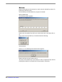
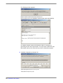
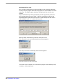
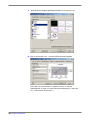
Operation Manual EMH-COM
Communication program for EMH-Electricity Meters
Edition: 03.03.2005
EMH-COM-PHB-E-2.00
All of the contents published in this operation manual are copyright.
Translating, reprinting, duplicating and also saving of this manual in data
processors requires the exclusive permission from EMH.
All of the trademarks named in this manual are the property of EMH or the
respective title holder.
EMH is certified accord. to DIN ISO 9001:2000 and continually endeavours to
improve the products.
The contents of this operation manual and the technical specifications can be
extended, altered or deleted without prior notice.
The description of the product specifications in this manual do not represent
part of a contract.
© 2004-2005 EMH Elektrizitätszähler GmbH & Co KG. All Rights reserved.
If you have any questions or inspirations you can contact us at:
EMH Elektrizitätszähler
GmbH & Co KG
Südring 5
D - 19243 Wittenburg
Tel.: +49(0)3 88 52 – 645-0
Fax.: +49(0)3 88 52 – 645-29
E-mail: [email protected]
Internet: www.emh-meter.de
2
Table of Contents
Chapter 1: Prologue ........................................................... 5
Overview of the program modules ..........................................................5
Explanation of how to use this manual ....................................................6
Chapter 2: Installation and release ................................... 7
Hardware-Requirements ........................................................................7
Program installation...............................................................................7
Release ..............................................................................................12
Request Key Code .........................................................................13
Receiving the key code ..................................................................16
Communication requirements ...............................................................17
Installation and settings of the optical communication adapter (OKK).17
Setting up of the local modem ........................................................17
Chapter 3: Program description....................................... 18
Menu- and symbol bar .........................................................................18
Program Description ............................................................................19
Menu File......................................................................................19
Menu option Transfer................................................................19
Menu option Exit ......................................................................19
Menu Direct ..................................................................................20
Menu option Set clock...............................................................20
Menu option Cumulate ..............................................................20
Menu option Identity numbers... ................................................21
Menu option Baud rate..............................................................21
Menu option RCR Relay cumulation position................................22
Menu option Test mode... .........................................................22
Menu option Manipulation... DMZ reset, ITZ reset V2.00 / V3.00,
ITZ reset V9.00 ........................................................................22
Menu option Single commands... Read command / Write
command ................................................................................23
Menu Read out..............................................................................24
Menu option Table 1 / Table 2 / Table 3 / Service table ...............24
Menu option Load profile ..........................................................25
Menu option Log book... ...........................................................26
Menu option Verification log book ..............................................27
Menu option User log book........................................................27
Menu option Installation check ..................................................27
Menu option eHZ automatic readout...........................................28
Menu option Comment..............................................................28
Menu option Convert ................................................................28
Menu option Graphic display......................................................29
Menu option Open... .................................................................32
Menu option Save.....................................................................32
Menu option Print... ..................................................................32
Menu option Control centre .......................................................32
Menu Setting.................................................................................33
Table of contents
3
Menu option Program settings... ................................................33
Register General..................................................................33
Register Modem ..................................................................35
Register Representation .......................................................37
Field Installation check...................................................................38
Register Export format .........................................................39
Menu Modem ................................................................................40
Menu Configuration .......................................................................40
Menu option Tariff settings ITZ... ...............................................40
Menu option Tariff settings DMZ... .............................................40
Menu option Tariff settings DHZ.................................................40
Menu option Transformer settings DHZ... ...................................40
Menu Info .....................................................................................41
Menu option Program info .........................................................41
Menu option Enter new product key... ........................................42
Menu option Release product key...............................................42
Questions and answers ........................................................................43
Load profile data .................................................................................44
Load profile import in Excel ..................................................................46
Index ............................................................................... 50
4
Table of contents
Chapter 1: Prologue
The EMH-COM software is a modular software, mit folgenden Kommunikationsund Konfigurationsmöglichkeiten:
Kommunikation
LZ..
PZ../PE..
DMTZ
ITZ
DMZ
DHZ
eHZ
D
D
D
D
D
D
D
D
D
D
Tarifkonfiguration
D
Transformer settings
In the following, all available program modules are described. It is possible that
your program version does not include some of the described program modules
which are included here.
Overview of the program modules
Basic program EMH-COM (Page 17 onwards)
Modem (Page 40 onwards)
EMH-COM
Write commands (page 20 onwards)
- cumulate
- transfer files
- set baud rate
- set identity number
- delete manipulation
Single commands (page 7)
- write command
- read command
Set clock (page 20)
Table 3 read (page 24)
LP/Graphic (page 29 onwards)
- load profile/read log book
- graphic LP-display
Installation check (page 27)
Tariff ITZ (page 40 onwards)
Tariff DHZ (page 40 onwards)
Tariff DMZ (page 40 onwards)
Transformer settings DHZ (page 40)
Communication
Communication
Communication
Communication
Communication
Communication
all types
VDEW 2.1
VDEW 2.0
DHZ
DMZ
ITZ
Control centre (Page 32 onwards)
MSCONS and mail for control centre
User – read out LP (page 25)
eHZ automatic readout (page 28)
Bluetooth OKK (page 33)
90 day-test version
Prolouge
5
Explanation of how to use this manual
The simple structure of the manual will help you to find the relevant topics
quickly. The manual is generally structured as follows:
complete path information
Explanation of a menu option, e.g of the menu File
File
M
Menu File
Transfers files and ends of the program
Short description
Explanation of a menu option, e.g menu option Transfer...
File > Transfer...
MO
Menu option Transfer...
Transfers saved set-, parameter-, tariff-, and ripple control files
Short description
Explanation of a register, e.g. register General
Setting >Program settings ... > General
R
Short description
6
Prolouge
Register General
Setting of the COM-interface, passwords and meter address
Chapter 2: Installation and release
Hardware-Requirements
The PC should fulfill at least the following requirements:
Processor:
Intel Pentium, 100 MHz or higher
RAM:
at least 32 MB RAM
Available hard disc memory: at least 50 MB
Operating system
Microsoft Windows 98/ME/2000/NT4.0 or XP
Accessories:
Optical Communication Adapter OKK (with
communication via the D0-interface),
Local modem for remote configuration with the
meter
Program installation
Procedure:
Start the file setup_emhcommas2000kyXXX.exe.
The following window appears:
Here you select the language version of EMH-COM.
Attention: After installation, the language of the basic program cannot be
changed.
Once the language has been set, click on
The following window appears:
Click on
OK
to continue.
Next >.
Installation and Release
7
The following window appears:
We recommend that you accept the proposed program folder. You may
however also select a different path.
To continue with the installation click on Next >.
If the selected program folder does not yet exist, e.g with a new installation,
then you will be asked if this folder should be created. To continue click on Yes,
in order to go back to the previous window and to set a new path or program
folder click on No.
8
Installation and Release
In the following window the program description is set which is used in the
start menu (Start > Programs...). You can set a new program description or
accept the proposal.
In order to continue with the installation click on
Next >.
Note : If the program creates no folder then, in the „start menu“ activate the
checkbox!
Please consider, that with a deactivation, the program can only start via the
Desktop Icon (if present) or directly from the index.
Installation and Release
9
In the following window you have the possibility to set if an icon should be
inserted on the desktop. With the help of the icon you can start the program
directly without having to go via the start menu.
In order to insert an icon, activate the checkbox. Click on
the installation.
Next >
to proceed with
The Setup now shows you once again all settings which you have made
concerning the installation. If you would like to make more changes then you
can go back to the previous installation steps by clicking on < Back.
Now click on
10 Installation and Release
Install.
At the end of the installation the following window appears:
Click on
Finish
to end the installation.
Note: If, after the installation, you want to start the program activate the
checkbox Start EMH—Program.
Otherwise the window is closed and the installation is ended.
Installation and Release 11
Release
Before the program can be executed or used it must be released by means of a
product key and a key code.
In the following it is described how a program is released.
Start the EMH-COM.
The following window appears:
Please enter the product-key which you received with the CD and then click on
OK.
Entry of the correct product-key is confirmed with the following
announcement.
Click on
OK.
The following announcement then appears.
Please read the note and confirm with OK.
The entry of the product-key is now ended. In order to request the key code for
releasing the program a renewed start of the program is necessary.
12 Installation and Release
Start the EMH-COM.
The following window appears:
The program offers you 2 possibilities to request the key code. You can select if
you want to receive the key code by E-mail or Fax. The option Request key code
per Mail is a more simple and quicker method to receive the key code. The option
Request key code per FAX is usually selected when your computer does not have an
internet connection.
Request Key Code
1. Possibility: Request key code per E-mail
Note: For this option internet connection is necessary.
Select the option
Now click on
Request key code per Mail.
Request key code.
Installation and Release 13
The following window appears:
Please read the announcement and click on
OK.
A new window from your Standard-E-mail-Program opens automatically.
The window already contains all information which is necessary for
processing the key code requirements. You only need to send the E-mail.
Shortly after this you will receive the key code to release the program.
2. Possibility: Request key code per Fax
Select the option
Then click on
14 Installation and Release
Request key code per FAX.
Request key code.
The printer menu from your standard printer then opens, e.g.:
You can now print out the key code request form on your printer.
The fax pre-printed form is as follows:
Please enter in the form the fax number where the key code should be
faxed to. You also have the possibility to receive the key code per E-mail.
For this, enter the E-mail address in the form to where the key code should
be sent. Then send the fax to:
EMH Elektrizitätszähler GmbH & Co KG
Fax-Number: +49-(0)3 88 52-645-29
You will receive the key code shortly.
Installation and Release 15
Receiving the key code
Once you have received the key code from EMH you can release the program.
For this, start the program either via the program icon on the desktop or via the
start menu. The window opens which you already know from the key code
request.
If you received the key code by E-mail then you can copy the key code from
the E-mail and insert it into the field. To do this, copy the key code into the
clipboard and then place the mouse cursor in the first empty box and use the
key combination „Ctrl + V“ to insert the key code.
When you have entered the key code (as above) click on OK.
If the key code is correct the following announcement appears:
If the key is incorrect the following announcement appears:
Enter the correct key code once again.
The release is now complete. You can start the program via the desktop icon (if
it exists) or via the start menu.
16 Installation and Release
Communication requirements
There are several possibilities to communicate with the meter. In the following,
communication via both the optical communication adapter OKK and the
electrical interface with a modem is described.
Installation and settings of the optical communication adapter (OKK)
The optical communication adapter OKK enables communication between a PC
and a meter. At the meter, communication to the optical data interface D0
takes place. Connection to the PC takes place, depending on the version and
design, via a COM-Port or a USB interface.
Procedure: Connect the optical communication adapter OKK to a free COM-Port
or a free USB interface on your PC (depending on the design of the OKK). If
you have an OKK with USB connection then a special USB driver must be
installed. The driver can be found on the CD-ROM which is contained in the
scope of delivery with the OKK. Tips for the installation of the driver can also be
found on the CD-ROM.
Note : Before communication can take place with the meter the interface must
be configured under Setting > Program settings ...> Register General(see page 33).
Setting up of the local modem
In order to communicate with the meter via the modem function some
parameters need to be defined for the local modem and the meter modem in
advance. For more information about this see page 35.
Note: For remote meter readout a standard commercial PC modem is used. On
the basis of our many years of experience we recommend an external modem
which is addressed with the Standard-Hayes-operations set. The advantage of
this modem is its audible loud speaker function and the LED status display.
With the set up of a communication line you can observe the connection
establishment (visually by means of the LED and acoustically by means of the
loud speaker).
A modern analog modem is able to call both analog meter modems and GSM
meter modems and is also able to read out the meter.
On the basis of our long term experience we would like to inform you of the
following:
Internal modem cards are technically equivalent however, if there are
problems, the error search is more difficult. Admittedly ISDN-cards offer the
possibility of an analog modem emulation via the so-called virtual COM-Ports
however, in practice they often cause many problems. Therefore it is not
recommended to use an ISDN-card.
Installation and Release 17
Chapter 3: Program description
Menu- and symbol bar
Note: The program consists of individual program modules (see page 5). If, in
the following, menu options and functions are described which do not appear in
your program then these program modules have not been released and are
therefore not available.
If you are interested in further modules please contact us.
In the upper part of the program window you can find the menu bar and below
this the symbol bar.
Via the symbol bar you can quickly access frequently used functions. If you go
over the symbol with the mouse a function description appears.
Set clock
Read out table 1
Read out table 2
Read out table 3
Read out service table
Read out load profile
Read out log book
Comment readout
Load profile-conversion
Load profile graphic display
Save protocol
Print protocol
Create modem connection
Separate modem connection
Cancel communication
18 Program description
Program Description
File
M
Menu File
Transfers files and ends the program
File > Transfer ...
MO
Menu option Transfer...
Transfers saved set-, parameter-, tariff- and ripple control files.
Procedure: Click on Transfer... Select the file which is to be transferred and click
on Open. The file is now transferred to the meter.
In order to close the window click on Cancel.
Note: Please make sure that in the selection field Files of type the file type is
selected which you want to transfer. Otherwise the file to be transferred will not
be shown in the window.
File > Exit
MO
Menu option Exit
Ends the program
Program description 19
Direct
M
Menu Direct
Menu option used to send commands to the meter
Direct > Set clock
MO
Menu option Set clock
Sends the PC time and the PC date
Here you have the possibility to read out the time and date from the meter or
to send the current PC time or PC date to the meter. For this, click on either
Read or Write.
Note: When you send the PC time and the PC date to the meter the time and
the date already set in the meter is then overwritten. Therefore pay careful
attention to the correct setting of the PC clock. On the right at the bottom of
the computer screen you can find the PC clock.
Direct > Cumulate
MO
Menu option Cumulate
Activates a reset in the meter
For the existing energy and maximum register new pre-values are formed. The
number of pre-values depends on the meter type.
Note: Usually the meters have a reset inhibition which is normally equal to the
length of a measuring period. That means, that after a reset, within this time
no renewed reset can be carried out.
20 Program description
Direct > Identity numbers...
MO
Menu option Identity numbers...
Sets and sends identity numbers to the meter
Here you can read out the identity number from the meter or send the identity
number to the meter. To do this click either on Read or Write. Select the
appropriate meter type via the option buttons.
Note: Please note that identity numbers with more than 8 digits cannot be
represented in the display.
Direct > Baud rate...
MO
Menu option Baud rate...
Sets and sends the start- and data baud rate for the external interface.
Here you can read out the start- and data baud rate of the meter or send them
to the meter. Please make sure that you have selected the appropriate meter in
advance via the option buttons.
Program description 21
Direct > RCR cumulation position...
MO
Menu option RCR Relay cumulation position...
Reads out and sets the relay contact position of the ripple control receiver.
Nach Aktivierung des Menüpunktes öffnet sich folgendes Fenster:
Here you have the possibility to read out the relay cumulation of the ripple
control receiver. For this click on Read. After the readout, the relevant relay
cumulation is marked with an „X“.
With a double click in the appropriate field the relay cumulation can be
changed.
In order to send the changed settings to the meter click on Write.
Direct > Test mode...
MO
Menu option Test mode...
Conversion of the pulse-LED
Here you can convert the function of the LED pulse and if it is supported by the
meter activate a certain tariff.
Note: The function test mode is not supported by all meters.
Direct > Manipulation...
MO
Menu option Manipulation... DMZ reset, ITZ reset V2.00 / V3.00, ITZ reset V9.00
Resets the manipultaion register of the DMZ or ITZ meter
Note: After activation of one of these menu options the relevant command is
sent to the meter immediately.
22 Program description
Direct > Single commands...
MO
Menu option Single commands... Read command
/ Write command
Sends read- or write commands to the meter
1. Example: Read out time from the meter
2. Note: Send identity number to the meter
(see also Menu option Identity numbers... on page 21)
Program description 23
Readout
M
Menu Read out
The menu Readout contains menu options for reading out the meter and also for
processing the data readouts.
Readout > Table 1 etc.
MO
Menu option Table 1 / Table 2 / Table 3 / Service table
Read out of the data lists from the meter
Table 1: Billing data
Table 2: Load profile with pre-adjustment of the load x days
(standard: last 40 days)
Table 3: EMH-internal data
Service table: Service data (momentary values)
Note: At the end of every meter read out, a BCC-Check takes place (with
special applications CRC). By means of a checksum sent by the meter a check is
carried out to see if the meter readout was totally correct (information: BCC =
xx OK).
With a faulty data read out, at the end of the read out the announcement
appears that the sent BCC is not the same as the calculated BCC. The total
readout is represented in red. If, in spite of many attempts, it is still not
possible to read out the meter correctly then refer to chapter „Questions and
answers“ page 43 onwards to find out possible causes.
To save the tables click on Readout > Save... Now select the index where you
want to save the file. In the field File name enter the name of the file and select
the desired file in the field Files of type > Readout files (*.tab). Then click on Save.
24 Program description
Readout > Load profile...
MO
Menu option Load profile ...
Read out of the load profile data from the meter.
Start date
Setting of the start date of the load profile to
be read out, start is 24:00 o’clock
End date
Setting of the end date of the load profile to
be read out, end is 24:00 o’clock
User – read out LP
Read out of the user – read out LP P.02
Note: This function can only be used if the
meter has a user - read out LP.
Read out compressed
Read out of the compressed load profile
Note: This function can only be used if the
meter supports the reading out of compressed
load profiles.
Read out complete
Read out of the complete load profile
Read out identity number additionally
In addition to the load profile the selected
meter address or identity number from the
selection list is read out in order to be able to
allocate the load profile to a meter at a later
date
Note: With the activation of the checkbox Read out complete, the readout of the
load profiles can take a long time depending on the size and number of
channels.
Program description 25
Button
Read out of single load profile channels,
selection leads to extension of the window.
First of all read out all available channels via the button read out available channels.
Then you can select the load profile channels to be read out by clicking on the
checkbox. To read out the marked load profile channels click on OK.
Readout > Log book...
MO
Menu option Log book...
Read out of the operation log book from the meter
26 Program description
Start date
Setting of the start date of the log book which
is to be read out, start is 24:00 o’clock
End date
Setting of the end date of the log book which
is to be read out, end is 24:00 o’clock
Read out complete
Read out of the complete log book
Read out identity number in additionally
In addition to the log book entries, the
selected meter addresses and identity
numbers in the selection list are read out in
order to be able to allcoate the log book
entries to the meter at a later date.
Readout > Verification log book
MO
Menu option Verification log book
Read out of the certification relevant log book P.99 (if configured )
In the verification relevant log book changes of the LED-pulse constants and
also of the pulse values from the P-and Q-output are saved. Altogether a
maximum of 46 entries are contained in the certification relevant log book.
Readout > User log book
MO
Menu option User log book
Read out of the user log book P.200 (if configured)
The user log book can be configured customer specific. As a rule the log book
contains events such as voltage failures and manipulation attempts with a time
stamp. Up to 204 events can be saved.
Readout > Installation check
MO
Menu option Installation check
Optional program module
For a detailed description see operation user manual EMH-COMBI-MASTER
2000.
Program description 27
Readout > eHZ automatic readout
MO
Menu option eHZ automatic readout
Automatic readout of electronic domestic meters eHZ
Note: If EMH-COM does not receive a data telegram within 14 seconds, the
EMH mobile cuts off the data readout (Timeout).
Readout > Comment
MO
Menu option Comment
Comments line by line the read out tables, load profiles and log books.
Example: Table 1
without comments:
with comments:
Note: The table, load profiles and log books are always read out without
comments. A comment is also only possible after the readout.
Readout > Convert
MO
Menu option Convert
Conversion of load profile data as preparation for data export
Example:
Load profile data after conversion
Note: An explanation of the load profile conversion can be found in the chapter
Fehler! Verweisquelle konnte nicht gefunden werden., page Fehler!
Textmarke nicht definiert..
28 Program description
Attention: After a conversion for a data export, a graphic load profile display is
no longer possible!
Export of the load profile data
To export the load profile click on Readout > Save ...
Select the index in which the file should be saved and enter the name of the file
in the field File name. As the file type select load profile export (*.txt) and click
on Save.
Afterwards you can import the file in a table calculation program
e.g. MS Excel, (for more information see page Fehler! Textmarke nicht
definiert.).
Readout > Graphic display
MO
Menu option Graphic display
Graphic display of load profile data
Note: The x-axis (abscisse) describes the time, the y-axis (ordinate) the
performance. For every channel a separate scaling of the y-axis can be
represented. This must be pre-defined Readout > Graphic display > Channel > Selection.
With the horizontal scrolling beam you can move the time axis.
With the sliding controller Zoom which can be found in the lower area of the
window it is possible to make the view field of the load profile curve larger or
smaller.
If several days are shown in the graphic then you can change over to a daily
display via a double click on one of the shown dates.
The cursor always marks a measuring period duration and the measuring period
duration can be moved with the cursor buttons Å Æ Ç È and also Pic Ç, Pic
È, Pos 1 and End.
When you move the cursor in the main area of the window then, in the field
below this, the relevant load profile values appear with information about the
time stamp and the status entries.
Program description 29
Menu bar of the graphic display
Graphic > Print...
Prints the content of the window
Graphic > Exit
Closes the graphic display, return to the main window
Channel
After activation of the menu option
window appears.
channel
the following
Via the buttons you can activate all channels or deactivate all
channels. Via the checkboxes you can however also activate or
deactivate individual channels.
In the load profile graphic individual calculations of each channel
In the graphic load profile display the scaling of the y-axis is
separately shown for every channel.
Set zero point of the Y-axis automatically
In the graphical load profile display the bottom limit of the yaxis is modified to reach a higher resolution.
Scaling only in the visible area
Representation of the load profile is scaled to the window size
depending on the zoom setting.
Transformer factor
Multiplication of the load profile data with a transformer
factor.
Here via the Dropdown-box you can set a transformer factor
for the load profile display. This setting has an effect on the
scaling of the Y-axis in the display. Provided that you use the
control centre of the program you can search for the
transformer factor which belongs to a meter/customer. For
this click on search for the transformer factor in the control centre data.
30 Program description
In the control centre data the identity number is then
searched for in order to determine the transformer factor.
If no identity number is found in the control centre data the
following window appears. The transformer factor then has to
be set manually in the dropdown-box.
Note: The transformer factor only has an effect on the graphic
load profile display and on the print. The load profile
conversion is not affected by this. Here a factor for export can
be specified independent of the graphic display.
Total evaluation
complete LP Here it is possible to display and print the evaluation of the total
load profile channel by channel.
Total evaluation
displayed area Here channel by channel evaluation of the load profile takes
place of the displayed area in the window. Here the functions
Display and Print are also available here.
Program description 31
Readout > Open...
MO
Menu option Open...
Opens files e.g. read out tables, load profiles (also converted), protocol files
etc.
Readout > Save...
MO
Menu option Save...
Saves files e.g. read out tables, load profiles (also converted), protocol files
Readout > Print...
MO
Menu option Print...
Prints the content of the window (data readout)
Readout > Control centre
MO
Menu option Control centre
Optional program module
For a detailed description see operation user manual EMH-COMBI-MASTER
2000.
32 Program description
Setting
M
Menu Setting
Setting possibilities for interfaces, modems, passwords, program representation
etc.
Setting > Program settings...
MO
Menu option Program settings...
Setting possibilities for interfaces, modems, passwords, program representation
etc.
Setting > Program settings... > General
R
Register General
Setting of the COM-interface, passwords and meter-address
Port
Setting of the COM-Port when using an optical communication
adapter OKK
Note: In order to determine the COM-Port when using an OKK
with USB connection look under Start > Settings > System control >
System-[Hardware]-device manager. Further information about this
can be found on the CD-ROM which is included in delivery with
the OKK.
Baud rate
Setting of the interface speed
Note: When using an OKK you should always use
Mode C
.
Program description 33
Bluetooth OKK
Activate this checkbox when a Bluetooth-OKK is used.
Login-password
Input of the login-password
With activation of this menu option, when logging in, a
password is sent to the meter. The password is saved in code
with the program settings.
W5-password
Input of the W5-password
Certain set commands (e.g setting of the clock time, writing of
the identity number) are only sent to the meter with
information about the W5 password. The pre-setting 00000000
must only be changed if a different password was agreed on.
Meter-address
Input of the meter-address
Note: This information is only important if the meter has a
meter-address. The meter-address only applies to the meters
electrical interface and therefore only comes into question with
a remote readout or a special solution. The meter-address can
be discovered by reading out the service table. The OBIS-code
for the meter-address is 0.0.0.
Note: If you have any problems with connection then please read the chapter
„Questions and answers“ page 43 onwards.
34 Program description
Setting > Program settings... > Modem
R
Register Modem
Setting of the local modem and the meter modem.
Telephone number
Entry of the telephone number of the meter modem
to be called
Note: If dialing a number for an outside line is
necessary then (often with telephone sets), this
number must be at the front of the telephone
number. Then enter a „w“. The „w“ causes a short
dialing break after reaching the network before dialing
further. If the „w“ does not operate property then
please contact the telephone administrator and ask
for the interval signal.
Local modem initialization
Selecting the local modem to be used
Note: The modems which are most frequently used
are listed. If your modem is not included in the list
then select the setting allg. Hayes-Modem;AT&FE0X3. This
setting functions with most types of modems.
Program description 35
Field meter modem selection Selection of the meter modem to be dialed.
EMH-COM supports meter modems from the
manufacturer Dr. Neuhaus (ZDUE), Görlitz (ENC
280), Elster (DM 100) and Sparkline Modem.
Note: As a rule, for simple transparent modems it
is sufficient if you activate Auto-Transparent modem. In
the field Modem-Timeout as a standard 90 sec are
entered. This information causes the program to
be automatically interrupted if a „faultless“
connection does not occur. It is not recommended
to select a smaller value.
With meter modems which have a password
protection in the field Modem password the password
can be entered. If there is no password activated
in the meter modem then the field stays empty.
Path to the INI-files
36 Program description
In the path C:\Dokument and settings\All Users\Application
Data\EMH as a standard the files modem.ini and
telefon.ini are found.
The file modem.ini contains the modem types which
are listed in the selection field local modem
initialization. In the modem.ini further modem
types can be extended. This should however only
be performed by experienced users.
The file telefon.ini contains telephone numbers
which are listed in the selection field. In the
telefon.ini new telephone numbers can be entered
which are then available with every start of the
program in the selection box Telephone number.
Setting > Program settings... > Representation
R
Register Representation
Sets the software surface
Large tool buttons
The buttons in the tool bar are shown enlarged.
Flat tool buttons
The buttons in the tool bar are no longer shown as a
relief structure.
Enlarge font for protocol
The font of the data read out is larger.
Note: This function is especially helpful with monitors
with a very high resolution.
Program description 37
Field Installation check
38 Program description
Display clockwise
The voltages are displayed clockwise:
U1=0°, U2=240°, U3=120°
Display anticlockwise
The voltages are displayed anticlockwise:
U1=0°, U2=120°, U3=240° (EMH-Standard)
Setting > Program settings... > Export format
R
Register Export format
Setting the export formats for the export of load profiles.
Here you can define the layout of the text rows for the export of load profiles.
The row is composed from the field Data composition in the above shown
sequence.
With a double click, individual fields are inserted into or removed from the data
composition.
Example: 01.01.2005 TAB 09:15 TAB Value Channel 1 TAB Value Channel 2 TAB Status
Separator is always a TAB-character.
Program description 39
Modem
M
Menu Modem
Optional program module
For a detailed description see user manual EMH-COMBI-MASTER 2000.
Configuration
M
Menu Configuration
Tariff settings for ITZ, DMZ, DHZ and also transformer setting for the DHZ
Configuration > Tariff setting ITZ...
MO
Menu option Tariff settings ITZ...
Optional program module
For a detailed description see user manual EMH-COMBI-MASTER 2000.
Configuration > Tariff setting DMZ...
MO
Menu option Tariff settings DMZ...
Optional program module
For a detailed description see user manual EMH-COMBI-MASTER 2000.
Configuration > Tariff setting DHZ...
MO
Menu option Tariff settings DHZ...
Optional program module
For a detailed description see user manual EMH-COMBI-MASTER 2000.
Configuration > Transformer setting DHZ...
MO
Menu option Transformer settings DHZ...
Optional program module
For a detailed description see user manual EMH-COMBI-MASTER 2000.
40 Program description
Info
M
Menu Info
Program information and release options
Info > Program info
MO
Menu option Program info
Program information
The menu option Program info contains information about the program and also
the areas of application.
Here you also receive the path information for the INI- and control centre files
and also the save files. The meter types which the program can communicate
with are also listed here.
If the installed program is a 90 day test version then it is shown here how
many days the program will still run for.
Program description 41
Info > Enter new product key...
MO
Menu option Enter new product key...
Entering a new product key for releasing further program modules
Procedure: The release of new program modules takes place as described in
chapter Release, page 12.
Info > Release product key...
MO
Menu option Release product key...
Requesting a new key code and releasing further program modules
Procedure: The release of new program modules takes place as described in
chapter Release, page 12.
42 Program description
Questions and answers
1. No communication to the meter takes place. After a few seconds the
announcement Timeout in the communication, Login not possible appears.
Possible causes :
-
The optical communication adapter is not attached properly or not
connected correctly.
-
The interface is not set correctly. When using an optical communication
adapter OKK please check the information for the COM-Port in the menu
Settings. Perhaps you must select another COM-Port.
-
The baud rate is not selected correctly. When using an optical
communication adapter OKK select in the menu Settings-Mode C. With this
setting, the PC and the meter set the optimal baud rate themselves.
2. Communication with the meter takes place however, the read out seems to
be faulty. After ending the communication the error announcement appears
that the BCC check was incorrect.
Possible causes :
-
With laptops the energy saving function can be activated which switches
off the hard disc after a certain period of time. If a hard disc access then
takes place (e.g. for the saving of storage area elsewhere), it is not
possible to access the hard disc immediately. Delays in the program
operation then occur and this can cause reading errors. In this case
deactivate the energy saving function via Start > Settings > Control Panel >
Power Options.
-
Your PC does not have enough RAM (Random Access Memory). If less
than 32 MB are installed then often the RAM has to be put on to a hard
disc. With some computers, due to delays, reading mistakes are caused.
-
The Buffer (FIFO) of the serial interface has not been set correctly. With
transmission problems try out different settings. Unfortunately a general
setting tip cannot be given.
-
When using a laptop and a passive optical communication adapter OKK
then, due to a reduced voltage supply, the voltage at the serial interface
is no longer enough for a faultless data transmission. In this case we
recommend using an optical communication adapter OKK with an USB
connection.
Program description 43
Load profile data
The meter sends for example the following load profile data:
/EMH4\@01LZQJC0014F
_P0_()_`
P.01(10304280000;10304290000)
_P.01(1030428001500)(00000000)(15)(2)(1.5)(kW)(3.5)(kvar)
(1.484)(0.600)
(1.480)(0.600)
...
This format can be converted by EMH-COMBI-MASTER 2000 so that the data
can be saved as a changed text file and then imported into a table calculation
e.g. MS Excel. When table 2 from the meter (pre-configured with load profiles)
or the load profile is read out via the menu option Readout > Load Profile..., the
meter sends all measured load profile channels. Depending on the type or
configuration of the meter the load profile channels can be defined differently.
The load profile contains information about which OBIS value (OBIS=ObjectIdentification-System) stands for the individual channels.
Explanation of the rows:
P.01(1030428001500)(00000000)(15)(2)(1.5)(kW)(3.5)(kvar):
(1.5)
(kW)
(3.5)
(kvar)
OBIS code of the first channel (W+)
Unit of the first channel
OBIS code of the second channel (WQ+)
Unit of the second channel
Explanation of the rows (1.484)(0.600):
(1.484) 1,484 kW
(0.600) 0,600 kvar
After conversion, the load profile file (without separators) is as follows1:
Date
28.04.04
28.04.04
Start
00:00
00:15
End
00:15
00:30
1.5
1,484
1,48
3.5kvar Su/Wi
0,6
S
0,6
S
Status
0000 0000
0000 0000
Every row is equal to a measuring period (usually 15 minutes) and contains
information about the start- and end time. If the meter supports information
about the season identifier then S for summer time or W for winter time is
entered. The status column contains information about certain events which the
meter saves (for the construction see VDEW requirement specifications). These
events are mainly voltage failure/return, setting the clock, season change
(winter/summer time), cumulation etc. If nothing occurs then 0000 0000 is the
output.
1
The layout of the text rows can be changed via
44 Program description
Setting > Program settings... > Export format.
Events can occur within a measuring period individually or with other events
together. The following tables show a few examples:
One event per measuring period
Meaning
Measured value interrupted
Season change
Reset
Clock set
Voltage return
Voltage failure
Entry in the load profile
0000
0000
0000
0000
0000
0000
0004
0008
0010
0020
0040
0080
Two events per measuring period
Meaning
Clock set + Measured value interrupted
Clock set + Season change
Clock set + Reset
Voltage recovery + Reset
Power failure + Voltage recovery
Entry in the load profile
0000 0024
0000 0028
0000 0030
0000 0050
0000 00C0
Three events per measuring period
Meaning
Clock set + Reset + Season change
Entry in the load profile
0000 0038
Program description 45
Load profile import in Excel
The exported load profile file (here named
opened:
Musterlastprofil)
looks as follows when
In order to import the file Musterlastprofil in Excel and to represent the load profile
graphically proceed as follows:
1. Open Excel.
2. Click on
Datei > Öffnen.
3. Select the file type
seen.
4. Open the file
46 Program description
Dateityp (*.prn; *.txt; *.csv).
Musterlastprofil.
The file
Musterlastprofil
can now be
5. In the following window click on
Ende.
6. Mark the desired display area, e.g. 1 day over the columns A to E.
Program description 47
7.
Now call up the Diagram-Assistant and select the
8. Click on the button
Weiter >
Standardtypen Linie.
until the following window appears
In the box Diagrammtitel enter for example Load profile, in the box
Rubrikenachse (X) enter Time and in the box Größenachse (Y) enter W+,
WQ+. Then click on the box Weiter >.
48 Program description
9.
In the following window you must decide if the diagram should be included
on the active page or if a new page should be created for the diagram.
Then click on the button Ende.
10. In this example we have decided to create a new page. Excel has created
a new page for the title Diagramm, on which the load profile is graphically
represented.
Program description 49
Index
B
M
baud rate ......................................................5, 21, 43
Bluetooth OKK .................................................... 5, 34
momentary values................................................... 24
MSCONS................................................................... 5
C
O
comment................................................................ 28
COM-Port ....................................................17, 33, 43
control centre .......................................... 5, 30, 31, 41
control centre file ................................................ 41
conversion............................................. 28, 29, 31, 44
OBIS ...................................................................... 44
optical communication adapter OKK3, 5, 7, 17, 33, 34,
43
D
pre-values .............................................................. 20
product-key ............................................................ 12
D0 ......................................................................... 17
data export........................................................28, 29
load profile export ............................................... 29
data read out............................................... 24, 28, 32
data readout
readout ........................ 5, 17, 18, 22, 24, 25, 28, 34
date
set date .............................................................. 20
E
eHZ readout ....................................................... 5, 28
G
graphic display............................................. 18, 29, 30
graphic load profile display ...........................29, 30, 31
I
interfaces ............................................................... 33
COM-Port.................................................17, 33, 43
optical interface .................................................. 17
serial interface .................................................... 43
USB interface ........................................... 17, 33, 43
K
key code ................................ 3, 12, 13, 14, 15, 16, 42
L
load profile5, 18, 25, 26, 28, 29, 30, 31, 32, 39, 44, 45,
46, 49
compressed load profile ....................................... 25
load profile data ........................... 25, 28, 29, 30, 44
load profile export................................................... 29
log book .......................................5, 18, 25, 26, 27, 28
operation log book ....................5, 18, 25, 26, 27, 28
User log book...................................................... 27
login-password ....................................................... 34
50 Index
P
R
read command.......................................................... 5
readout ............................ 5, 17, 18, 22, 24, 25, 28, 34
readout lists
service table ................................................. 18, 34
table 1................................................................ 18
table 2.......................................................... 18, 44
table 3................................................................ 18
release .......................................... 3, 7, 14, 16, 41, 42
reset .............................................................3, 20, 22
reset inhibition ........................................................ 20
ripple control file ................................................. 6, 19
S
season ................................................................... 44
serial interface ........................................................ 43
service table ..................................................... 18, 34
set date.................................................................. 20
set time.................................................................. 20
T
table 1.................................................................... 18
table 2.............................................................. 18, 44
table 3.................................................................... 18
test mode ............................................................... 22
time
set time .............................................................. 20
transformer setting ................................................. 40
U
USB interface...............................................17, 33, 43
user log book.......................................................... 27
W
W5-password.......................................................... 34
write command ................................................... 5, 23