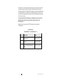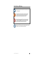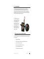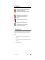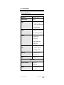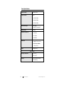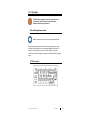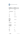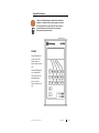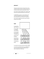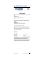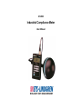
1
HI-3804 Industrial Compliance Meter User Manual ETS-Lindgren Inc. reserves the right to make changes to any products herein to improve functioning or design. Although the information in this document has been carefully reviewed and is believed to be reliable, ETS-Lindgren does not assume any liability arising out of the application or use of any product or circuit described herein; nor does it convey any license under its patent rights nor the rights of others. All trademarks are the property of their respective owners. © Copyright 1999–2014 by ETS-Lindgren Inc. All Rights Reserved. No part of this document may be copied by any means without written permission from ETS-Lindgren Inc. Trademarks used in this document: The ETS-Lindgren logo is a trademark of ETS-Lindgren Inc. Revision Record HI-3804 MANUAL | Part #H-600085, Rev. C ii Revision Description Date A Initial Release February, 1999 B Rebrand November, 2008 C Updated Probe Specifications table September, 2014 www.ets-lindgren.com Table of Contents Notes, Cautions, and Warnings ................................................ v 1.0 Introduction .......................................................................... 7 ETS-Lindgren Product Information Bulletin ................................................. 7 2.0 Maintenance ......................................................................... 9 Battery Replacement .................................................................................. 9 Service Procedures .................................................................................. 10 Contacting ETS-Lindgren .................................................................. 10 Sending a Component for Service..................................................... 10 Calibration Services and Annual Calibration...................................... 10 3.0 Specifications ..................................................................... 11 Readout Specifications ............................................................................. 11 Probe Specifications ................................................................................. 12 4.0 Operation ............................................................................ 13 Before Making Measurements .................................................................. 13 LCD Description........................................................................................ 13 Keypad Description ................................................................................... 15 POWER ............................................................................................ 15 MODE SELECT ................................................................................ 16 RANGE ............................................................................................. 16 MAX.................................................................................................. 17 E/H ................................................................................................... 17 BAT .................................................................................................. 18 UNITS ............................................................................................... 18 CLEAR DATA ................................................................................... 18 LOG .................................................................................................. 18 PREV................................................................................................ 19 NEXT ................................................................................................ 19 FREQ ............................................................................................... 19 ZERO ............................................................................................... 20 TEMP ............................................................................................... 20 Measurement Techniques......................................................................... 20 Taking Measurements ...................................................................... 20 www.ets-lindgren.com iii Zeroing ............................................................................................. 21 Appendix A: Warranty ............................................................. 23 Appendix B: EC Declaration of Conformity .......................... 25 iv www.ets-lindgren.com Notes, Cautions, and Warnings Note: Denotes helpful information intended to provide tips for better use of the product. Caution: Denotes a hazard. Failure to follow instructions could result in minor personal injury and/or property damage. Included text gives proper procedures. Warning: Denotes a hazard. Failure to follow instructions could result in SEVERE personal injury and/or property damage. Included text gives proper procedures. Note: See the ETS-Lindgren Product Information Bulletin for safety, regulatory, and other product marking information. www.ets-lindgren.com v This page intentionally left blank. vi www.ets-lindgren.com 1.0 Introduction The ETS-Lindgren Holaday HI-3804 Industrial Compliance Meter is a portable, battery-operated measurement system designed to assist in the evaluation of electric and magnetic fields (E and H fields). The HI-3804 finds applications in determining the amount of energy radiated by industrial sealers, ovens, heaters, dryers, and similar equipment. The HI-3804 consists of a readout and a probe. The readout includes a custom LCD and a front panel keypad. All selection and control functions are input through the keypad. This keypad is configured in a matrix, allowing access to twelve functions. ETS-Lindgren Product Information Bulletin See the ETS-Lindgren Product Information Bulletin included with your shipment for the following: Warranty information Safety, regulatory, and other product marking information Steps to receive your shipment Steps to return a component for service ETS-Lindgren calibration service ETS-Lindgren contact information www.ets-lindgren.com Introduction 7 This page intentionally left blank. 8 Introduction www.ets-lindgren.com 2.0 Maintenance CAUTION: Before performing any maintenance, follow the safety information in the ETS-Lindgren Product Information Bulletin included with your shipment. WARNING: Maintenance of the HI-3804 is limited to external components such as batteries, cables, or connectors. To prevent electrical shock, do not remove cover. Warranty may be void if the housing is opened. WARRANTY If you have any questions concerning maintenance, contact ETS-Lindgren Customer Service. Battery Replacement Standard 9-volt alkaline batteries may be used to power the HI-3804 Industrial Compliance Meter. When the battery symbol appears on the LCD, change the batteries. 1. Remove the end plate on the bottom of the readout to access the batteries. 2. Follow the instructions on the back of the readout to insert the batteries correctly. 3. Replace the end plate. www.ets-lindgren.com Maintenance 9 Service Procedures CONTACTING ETS-LINDGREN Note: Please see www.ets-lindgren.com for a list of ETS-Lindgren offices, including phone and email contact information. SENDING A COMPONENT FOR SERVICE For the steps to return a system or system component to ETS-Lindgren for service, see the Product Information Bulletin included with your shipment. CALIBRATION SERVICES AND ANNUAL CALIBRATION See the Product Information Bulletin included with your shipment for information on ETS-Lindgren calibration services. 10 Maintenance www.ets-lindgren.com 3.0 Specifications Readout Specifications Operating Life: Approximately 40 hours Probe Connectivity: 5-pin DIN Display: Custom LCD: 3.5 digits, 1.0-in (25.4 mm) character height 21 segment bar graph Logging: Logging up to 112 data points On-board data review capability Functions: Peak (Max) Hold Probe Zeroing Battery Voltage Display Data Logging Battery: 9-volt alkaline batteries (2) NEDA 1604A, or better Dimensions: 15.2 cm x 8.9 cm x 4.4 cm 6.0 in x 3.5 in x 1.8 in Weight: 0.64 kg (1.42 lb) Environmental Operating Temperature: 10°C to 40°C 50°F to 104°F Humidity: www.ets-lindgren.com 0% to 90% relative humidity, non-condensing Specifications 11 Probe Specifications Frequency Range: 10 MHz–42 MHz Frequency Bands: Three: 10 MHz–20 MHz 20 MHz–35 MHz 35 MHz–42 MHz Measurement Range: Three ranges: 2 2 0.5 mW/cm –50.0 mW/cm Probe Overload: 1 mW/cm Calibration Frequencies: 13.56 MHz 2 27.12 MHz 40.68 MHz Dimensions: Length: 35.6 cm (14.0 in) Probe cover diameter: 13.2 cm (5.2 in) Weight: 0.28 kg (0.62 lb) Environmental Operating Temperature: 10°C to 40°C 50°F to 104°F Humidity: 12 Specifications 0% to 90% relative humidity, non-condensing www.ets-lindgren.com 4.0 Operation CAUTION: Before placing into operation, follow the safety information in the ETS-Lindgren Product Information Bulletin included with your shipment. Before Making Measurements Note: The meter must be zeroed prior to making measurements. Before making any measurements, determine the operating frequency of the emitter(s) that will be surveyed for electromagnetic radiation field levels. The frequency of the emitter(s) must not be lower than 10 MHz or higher than 42 MHz, which is the rated frequency range of the HI-3804 Industrial Compliance Meter. LCD Description www.ets-lindgren.com Operation 13 Note: Not all of the symbols are active on the HI-3804. Symbol / Indicator Description Under Range Bar Graph Over Range Alarm Active MAX Maximum Reading Units Of Measure Cursor Block Digital Display XYZ Axis Battery AUTO 14 Auto Range Operation www.ets-lindgren.com Keypad Description WARRANTY Caution: The HI-3804 keypad is comprised of membrane switches. To activate a switch, press gently on the center of the key with the tip of your finger. Do not use hard or pointed objects to press the keys, or any resulting damage may void your warranty. POWER Press POWER to turn on the readout. The readout does not require warm-up prior to use. Press POWER again to turn off the readout. The readout does not automatically shut down, so turn the readout off when not in use. www.ets-lindgren.com Operation 15 MODE SELECT The keypad uses a matrix for the top three rows of keys. The function of each key depends on the location of the cursor in the LCD. When the readout is turned on, the cursor is located in the first of the four function columns. To access a function in this mode, press the corresponding arrow key. For example, to toggle between electric and magnetic field measurements, press the lowest arrow key. Press MODE SELECT to move the cursor to the right, advancing to the next column. Each time MODE SELECT is pressed, the cursor moves another position to the right, and then returns to the first position. This matrix allows a total of 12 functions to be assigned to the top three rows of keys. Following is a description of each of the functions. RANGE This changes the fixed ranges or scales. When turned on, the HI-3804 is in AUTO RANGE mode, and determines the correct range within the current mode (E or H field) according to the detected field level. As the field being measured increases or decreases, the range is automatically selected for best resolution and accuracy. In some situations it may be helpful to fix the scale of the HI-3804. Press RANGE once to select the current scale setting. Each time you press RANGE the scale moves to the next least sensitive range. When the least sensitive scale is reached, it starts again at the most sensitive range. 16 Operation www.ets-lindgren.com To return to AUTO RANGE mode, press and hold RANGE for two seconds until AUTO displays. MAX Note: The maximum value is not affected by the CLEAR DATA key. The maximum value is cleared when: The readout is powered up. The MAX key is released. The unit of measure is changed. MAX displays the maximum reading. During field measurements, the processor continually monitors and stores the highest measured field value. To recall and display this value, press MAX. The value displays as long as MAX is pressed. When MAX is released, the value displays for two seconds, and then the MAX memory location is cleared and a new maximum reading is accumulated. Note: If the maximum reading is over full scale for the range, an over range alarm will sound and the over range indicator ( ► ) will display. E/H Toggles the measurement mode between electric and magnetic field readings. The current measurement units are displayed to the right of the reading. For E field measurements, V/m will illuminate; for H field measurements, A/m will illuminate. Note: The field being measured when the HI-3804 was last turned off becomes the default field when the HI-3804 is turned on again. www.ets-lindgren.com Operation 17 BAT Displays battery status. After BAT is pressed, the battery voltage displays for two seconds and then the readout returns to measurement mode. When the battery voltage drops below a preset limit, the battery symbol will blink, indicating that the batteries need replacing. If the battery voltage is allowed to drop below the limit required for proper device operation, the LCD will turn blank. UNITS Instructs the probe to change the units of measure and displays the new units. 2 When measuring the electric field, UNITS toggles between mW/cm and V/m. In 2 the magnetic field, it toggles between mW/cm and mA/m. CLEAR DATA Clears all readings from datalog memory. To perform this function, press and hold CLEAR DATA. The characters clr will flash on the display for two seconds. Continue pressing CLEAR DATA until 000 appears, indicating that datalog memory is cleared. Release the key to return the readout to measurement mode. Note: If CLEAR DATA is released while the clr characters are flashing, datalog memory is unaffected. This helps prevent accidental erasing of data. LOG Saves the current measurement in datalog memory. As this occurs, the three-digit identification number of the reading momentarily displays. The data stored includes values, units of measure, over/under range indication, and active axes. Up to 150 measurements may be stored. When datalog memory is full, pressing LOG replaces the value stored in location 150 with the new value; all other memory locations are unchanged. Note: If LOG is pressed for longer than two seconds, the data just logged is displayed. 18 Operation www.ets-lindgren.com PREV Accesses the last value stored in datalog memory. When PREV is pressed, the three-digit identification number of the stored value displays for one second and then the stored value displays. This value displays as long as the PREV key remains pressed. Two seconds after releasing the key the readout returns to measurement mode. Pressing the PREV key at that point decrements the displayed value toward the beginning of memory (value 001). If PREV is pressed while viewing value 001, the readout wraps around to the highest stored identification number. NEXT Accesses the next value stored in datalog memory. NEXT is similar to the PREV key, except that when you continue to press NEXT, it increments the displayed value toward the end of datalog memory. Additionally, if NEXT is pressed while viewing the highest stored value, the readout wraps around to identification number 001. Note: If an under range value is logged and displayed, the measured value and the under range indicator will appear. If an over range value is logged and displayed, an over range alarm will sound and the over range indicator ( ► ) will appear. FREQ Allows the frequency to be changed by the user. When pressed, the display reads F-1 (13.56 MHZ), F-2 (27.12 MHZ), or F-3 (40.68 MHZ). These values can also be found in the lower right corner on the front of the readout. www.ets-lindgren.com Operation 19 ZERO Transmits a zero command to the probe. This zeroes all ranges and axes, which includes both sets of sensors, electric, and magnetic fields. It establishes a baseline for measurements by sampling all axes and ranges and subtracting those values from each subsequent measurement. Note: The meter must be zeroed prior to making measurements. TEMP Displays the current temperature of the probe in degrees Celsius. Press and release TEMP and the temperature will display for two seconds, and then the readout will change back to measurement mode. Measurement Techniques Caution: When taking measurements of electromagnetic fields, there is a potential of exposure to high or excessive levels of electromagnetic energy. Approach the energy source slowly and carefully. If extremely high amounts are present, immediately leave the area. TAKING MEASUREMENTS Hold the readout in one hand and the probe in the other. If you know where the energy source is, approach it slowly, and then point the probe towards it. If you are not sure where the source is, hold the probe above your head, pointed up at about 45 degrees. To find where the maximum reading is coming from, rotate the probe in a circle. 20 Operation www.ets-lindgren.com For accurate readings, follow these guidelines: The arm holding the probe should extend away from your body as far as possible without becoming uncomfortable, and the probe should point towards the energy source. Measurements in the electric field from low frequency antenna systems often require special techniques because the human body acts as a scatterer and introduces errors. The best technique to use when making measurements near antenna systems is to place the probe next to the readout on a non-metallic stand such as a wooden ladder or cardboard box. Then stand back and read it without touching it. Note: The human body does not greatly affect magnetic fields. The techniques described previously are more critical for electric fields. Scan the probe through the field to obtain a maximum reading. The protective cover on the probe should not be closer than four inches (10 cm) to the surface of the energy source; otherwise, the readings may be inaccurate. ZEROING When the readout sends a zero command, the probe must be in a zero field environment. This is because the zero command causes the multiplexer (through the processor) to perform a normal read cycle on all axis signals. This is executed for all three ranges, both E and H fields. When the processor receives all the zero-field signal values, it stores them in a special register; the values are subtracted from all subsequent measurements. Therefore, a probe which is zeroed when not in a zero field environment will give erroneous readings. Turn the readout on. A few seconds after you turn the system on it is ready for operation (measurement). The LCD displays the observed value and the units of measure. The bar graph displayed on the LCD represents an analog approximation of the measured field. Each bar graph segment represents 5% of the full scale reading in the current range. The bar graph is updated 7.6 times per second and the digital display is updated 1.9 times per second. www.ets-lindgren.com Operation 21 When the measured field strength is below 5% of full scale for the range being used, the under range indicator ( ◄ ) will appear and the display will flash on and off. When possible, switch the range to permit a field strength reading which does not trigger the under range indicator. If the field strength exceeds full scale, the over range indicator ( ► ) appears and an alarm will sound. Select the next appropriate range. 22 Operation www.ets-lindgren.com Appendix A: Warranty Note: See the Product Information Bulletin included with your shipment for the complete ETS-Lindgren warranty for your HI-3804. DURATION OF WARRANTIES FOR HI-3804 All product warranties, except the warranty of title, and all remedies for warranty failures are limited to one year. Product Warranted Duration of Warranty Period HI-3804 Industrial Compliance Meter 1 Year www.ets-lindgren.com Warranty 23 This page intentionally left blank. 24 Warranty www.ets-lindgren.com Appendix B: EC Declaration of Conformity www.ets-lindgren.com EC Declaration of Conformity 25