1
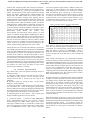
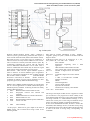
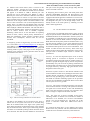
International Journal of Engineering and Technical Research (IJETR) ISSN: 2321-0869, Volume-3, Issue-2, February 2015 Vehicle Tracking System using Universal Data, Voice Acceptor, Converter and Transmitter with access to Web and Smart Phone Vivekanand Krishnaji Joshi, Rahul Mandlik Abstract— The important function of vehicle tracking system is to collect geographical location of the vehicle using GPS receiver and send it over wireless network to the Monitor and Control Station (MCS) where it can be viewed on the Digital Map. It is highly desirable to design vehicle tracking system with portable Vehicle Mounting Unit (VMU) having low weight, low power consumption and high efficiency. It should be able to send geographical data on any available wireless network like Wifi, Bluetooth, GSM/GPRS etc. and must have provision of receiving the same at MCS, Remote Computer accessible using Internet, and on Smart Phone. The location should be viewable in the vehicle itself to guide the Driver. There should also be provision of storing the geographical data in Memory if no wireless network is available. In this paper we discuss one such device named as UDVACT (Universal Data, Voice Acceptor, Converter and Transmitter). The paper presents inter-network connectivity with focus on Vehicle Tracking System. The UDVACT device will be fitted in the vehicle to be traced. The UDVAT have a provision of storing geographical data in the SD card with timestamp, sending data over Wifi or Bluetooth or GSM or GPRS wireless network. The UDVACT can be connected to the laptop (in the vehicle) using its RS232 or USB or Ethernet port and data can be viewed on the Digital map in the laptop. The same data can be accessed on the web site and on the smart phone. Index Terms— AT commands, Interconnection of wireless networks, MySQL and PHP integration, Vehicle tracking system using GPS and GSM. I. INTRODUCTION Wireless networks operate in various frequency bands. The frequency band is main criteria for deciding range of communication. The wireless networks supports various data rates and protocols suited for different applications. Often it is required to interconnect these networks, as range of one particular network may be available at some particular area and may not be available in another area, where there is possibility of having range of some other wireless network. The aim of project is to interconnect GSM/GPRS, Wi-Fi and Bluetooth network. It is also aimed to send data from or to Computer ports namely RS232, USB and Ethernet to any of these networks. Such device is designed and termed as Manuscript received February 22, 2015. Vivekanand Krishnaji Joshi, PG student, Department of Electronics & Telecommunication, GSMCOE, Savitribai Phule Pune University, Pune, India , 9923102358, Rahul Mandlik, Asst. Professor, Department of Electronics & Telecommunication, GSMCOE, Savitribai Phule Pune University, Pune, India , 77677833400. 260 Universal Data, Voice, Acceptor, Converter and Transmitter or UDVACT. In order to demonstrate the application of the UDVACT, Vehicle Tracking Application is selected. Vehicle tracking system application aims in showing location of vehicle on Google maps. UDVACT is installed in the vehicle to be traced. The GPS receiver inside the UDVACT senses the location of vehicle and sends data representing latitude, longitude and altitude of the vehicle at the output. This data can be send over Wifi, GPRS or Bluetooth Network to the Personnel Computer (PC) at the Monitor and Control Station (MCS) which is located far away from the vehicle. The PC has adequate software to display the location of the vehicle on the digital map. The PC at the MCS has a provision of Web server so that the location of vehicle can be seen on any remote PC by accessing the concerned Website named as http://www.GanbaSopan.com. The same vehicle location can be seen on the Smart Phone using Special mobile application named as Location_Finder. The location of the vehicle can be seen in the vehicle itself by diverting GPS receiver output to the either USB, RS232 or Ethernet port of the UDVACT. Any of the UDVACT port can be directly connected to the Laptop and location can be viewed on the Laptop which have adequate software to display location on digital map. If Laptop and any wireless network range is not available then location of vehicle can be stored on the SD card in the UDVACT with time stamp. The SD card can then read out to find out locations travelled. Some important applications are discussed below. A. Providing Emergency legal and Medical help: Vehicle tracking system can be deployed in the police patrolling vehicles as well as on the ambulances. When any accident take place, Police Control Room can divert the police vehicle and ambulance which are near to the accident place to help to the peoples in the accident in the Golden hour. This will save lives of the people. B. Time management of goods transport: It is essential to trace the vehicles transporting important goods, Inflammable fluids , Essential foods, Fuels like petrol, diesel, LPG cylinder for the lives of the people. The vehicle tracking system will help in time management of the goods and knowing their present status at each moment. C. Safety of the vehicle and peoples travelling through it: The vehicle tracking system can be equipped on Public Transport Vehicles like Buses, Taxis for preventing vehicle stealing, misuse of vehicles and prevention of crime. II. RELATED WORK Vehicle Tracking System is active area of research with several surveys [1], [2], [3], [4] on this topic. Although the main topic of this paper is interconnection of various wireless www.erpublication.org Vehicle Tracking System using Universal Data, Voice Acceptor, Converter and Transmitter with access to Web and Smart Phone networks and integrating them with Computer and Internet, the vehicle tracking system is taken as one of its application to describe it. Reference [1] presents the development of the remote vehicle tracking system which integrates the Global System for Mobile Communications (GSM) Modem and Google Map. The GSM modem at the control center will receive the coordinates through Short Message Service (SMS) and updates the main database. Reference [2] show the development of vehicle tracking system using the Global Positioning System (GPS) and Global System for Mobile Communications (GSM) modem is undertaken with the aim of enabling users to locate their vehicles with ease and in a convenient manner. The main hardware components of their system are u-blox NEO-6Q GPS receiver module, u-blox LEON-G100 GSM module and Arduino Uno microcontroller. The main focus of these papers is to send vehicle co-ordinates through GSM or GPRS network. But in some cases use of Wifi, Bluetooth or local available network is also possible and feasible. Also the previous papers do not take into account the situation in which no GSM or GPRS network coverage is available and location monitoring in the vehicle itself is not possible. Location monitoring in the vehicle would certainly guide the Driver of the vehicle. This paper takes into account all such situations. System uses any available network (This paper demonstrates GSM/GPRS along with Wifi and Bluetooth but inclusion of all other local level networks is possible). Even though any network is not available at the vehicle to send the location data, it can be stored in the SD card and at later time location sequence can be traced. This is particularly important for Police and Army officers, who trace the Naxals or Terrorist in the deep forest. The proposed UDVACT is not only designed for mounting in the vehicle but also designed light weight and portable so that our Soldiers can easily carry with them in some critical operations like combing or searching. III. SYSTEM DEVELOPMENT Fig.1 shows Total system. The System essentially consists of following sections: A. UDVACT module for receiving data from one network and sending to other network . In case of absence of any wireless network data is stored in the SD card of the UDVACT. B. Database system for storing the data - In this project MySQL is used as database C. Displaying of data on digital maps for local and remote user For remote user , who is accessing the system through internet , PHP is used for web page designing and Google map are used for displaying location of vehicle. For local or remote user authentication is required for accessing the data. D. Displaying data on Smart phone – This is done using design of Mobile application Location Finder. A. UDVACT module: It consists of GPS, GSM/GPRS, WIFI, BLUETOOTH receivers. The receivers converts concerned signal into UART format. Signals from UART output port of GPS receiver are connected to UART0 input port of microcontroller. Similarly signals from output UART port of GSM/GPRS receiver, Wifi receiver, Bluetooth 261 receiver are applied to input UART1, UART2, UART3 ports respectively of microcontroller. The signals from RS232, USB, Ethernet port of UDVACT are connected to UART4, USB, and Ethernet ports respectively of microcontroller. LPC4357 Arm cortex M4 is used as microcontroller. Program is written in the microcontroller to divert signals from one wireless network or port to another wireless network or port as summarized below network or port to another wireless network or port as summarized in the Table I. Table I: UDVACT INPUT - OUTPUT relationship The choice of selection of input and output port is left to User. The user selects the Input and Output port as per his requirement. For vehicle tracking system, input is selected as GPS and output is selected as GSM/GPRS or Wifi or Bluetooth. If none of these networks are available , user have option of storing data in the SD card for later viewing and analysis. GPS System is developed by U.S. Department of Defense and can be used by Civilians and military personnel. The civil signal SPS (Standard Position Service) can be used by public while military signal PPS (precision Position Service) can be used by authorized government agencies. Currently there are 28 C/A code is identification of satellite. GPS receiver is capable of recognizing all C/A codes. Thus by shifting and comparing each code with incoming satellite signal, complete match will eventually occur. The correction point is used to match and identify actual satellite [5]. Navigation message is a continuous stream of data transmitted at 50bps. It consists of System clock and correction value, Its own highly accurate orbital data (Ephemeris), Approximate orbital data of all satellites (Almanac) and System health. Navigation message consists of 25 frames per page. Each frame consists of 1500 bits. Each frame consists of 5 sub frames and there are 10 words per sub frame . Word number 1 and 2 consists of Telemetry word for synchronizing. Sub frame 1 consists of satellite clock and health status. Sub frame 2 and 3 consists of Ephemeris and sub frame 4 and 5 consists of almanac data [5]. DOP means Dilution of Precision - The accuracy with which position can be determined using GPS depends on accuracy of Pseudo range and geometrical configuration of satellites used. Coordinate Systems- Geoids is a reference surface for measuring height. National and International map references systems based on certain types of ellipsoids are called as datum. www.erpublication.org International Journal of Engineering and Technical Research (IJETR) ISSN: 2321-0869, Volume-3, Issue-2, February 2015 Fig. 1: Total System WGS-84 (World Geodetic System -1984) - WGS-84 is reference system, geocentrically positioned with respect to center of earth called as ECEF (Earth centered Earth Fixed) . Horizontal accuracy of 20 meters may be insufficient. A reference receiver is always used in addition to user receiver. This is located at accurately measured reference point. By continuously comparing user receiver with the reference receiver differential measurements can be made. This is called as Differential GPS. DGPS may be based on signal transit time or phase measurement of carrier signal. Data formats – GPS receivers require different signals in order to function. To ensure different types of appliances there are international standards for data exchange through data formats called as NMEA (National Marine Electronics Association) or RTCM (Radio Technical committee for Marine services special committee) or other proprietary protocols by different manufacturers[5]. NMEA-0183 is NMEA standard used today. It specifies data sets for various applications of GNSS (Global Navigation Satellite Systems ) and GPS . Following are data sets widely used for GPS applications 1. GGA GPS fixed data and fixed data for GPS 2. GLL Geographic location like latitude and longitude 3. GSA GNSS DOP and active satellite information 4. GSV GNSS satellites in view 5. RMC Recommended minimum specific GNSS data 6. VTG Course over data 7. ZDA Time and delay In this project , GPS receiver gives output in the form of NMEA strings. Out of which GGA string is used. It has following format. 262 GGA data set contains information of time , latitude , longitude , quality of system , number of satellites used and height as shown. $ GP GGA ,130305 ,4717.115 , N , 00833.912 , E , 1 , 08 , 0.94 , 00499 , M , * 58 <CR> <LF> indicate $ Start of dataset GP Information originating from a GPS appliances GGA GPS fixed data and fixed data for GPS 130305 UTC position time 13 hour 03 min.05.0 sec. 4717.115 Latitude 47 degree and 17.115 minutes. N North 00833.912 Longitude 8 degree and 33.912 minutes. E East 1 1- GPS , 0- No GPS and 2- DGPS 08 Number of satellites 0.94 HDOP 00499 Antenna height data M Unit for height in meters * Separator for checksum 58 Checksum for verifying entire dataset <CR> <LF> End of dataset The string at the output of GPS receiver is applied to UART port of LPC4357. The program first checks validity of the string and then reads the string in a file. It then checks whether the string collected is a valid $GPGGA message, if so it collects the various parts of the string into different arrays used to store data for latitude, longitude and timestamp. If user selects GSM/GPRS network, the data is send in the form SMS ( Short Message Service) to the other end by using AT commands. If user selects Wifi or Bluetooth then also data is send in the form of strings using corresponding AT commands. www.erpublication.org Vehicle Tracking System using Universal Data, Voice Acceptor, Converter and Transmitter with access to Web and Smart Phone AT commands are strings of data that begin with the prefix AT and can be sent to a communication module for the purpose of programming it. AT commands are related to asynchronous serial interface and can be sent using a program such as Hyper-Terminal in Windows, or directly from the microcontroller, over the RS232 interface. GPRS transmission system is provided by mobile operators and acquired data are sent to a server. Maximum transfer rate can be achieved by GPRS is 171.2 Kbps. Data transfer can be performed using UDP (User Datagram Protocol) or TCP/IP. Each module must have a GPRS SIM card provided by the mobile operator with a subscription or prepaid system for data transfer. The applications When activating the GPRS connection, one must specify the network parameters and the dialed phone number to establish a connection between the modem and a data server. Connection with an application located on a server is done as follows [6]: An AT command sets the properties to enable the GPRS modem to activate the GPRS connection whenever a data transfer is needed. An AT command sets authentication parameters, username and password that will be used to validate the connection. An AT commands defines the port connection to the server and UDP or TCPIP protocol. The connection starts with a dialing command. Some of the commands used to connect are: AT-Empty command empty, will always return the answer "OK", used in the AT format AT # USERID [= <user>] - Send names for network authentication used as AT #USERID = "net.vo" AT # PASSW = <pwd> - Send password to login, use as AT # PASSW AT + CPIN [= <pin> [, <newpin> ]] Send your PIN, use the form AT + CPIN =2649 (PIN) AT + CREG =? - After you insert the SIM card PIN the system is waiting until the connection is made. The command was used in the form: AT + CREG? AT + CGDCONT = 1 The IP connection through GGSN server name "net.vodafone.ro" without data compression or packet header. The command used was: AT +CGDCONT = 1, "ip", "net.vodafone.ro", "0.0.0.0", 0.0 AT # GPRS [= [ <mode> ]] – GPRS activation with 1, deactivation with 0 transmission has been activated with AT # GPRS = 1. AT # GPRS? interrogates the modem status at#sktd=0 Socket type used is the TCP, listening port number is 2222, server's IP address is "86.125.93.184", and the connection closes when the server closes the connection port. The command used was: AT # SKTD =0.2222, "86.125.93.184", 0 Transmitting data follows after this sequence. Practically everything is received by the module over the serial interface will be sent to the server. The Bluetooth module also works on AT commands as follows. ATAn -establishing connection with the devices n = 1-8 ATB? - displays addresses of slave devices connected ATD=xxxxxxxxxxxx - defines a 12-digit address for a device connected ATEX - set echo for the USART transmission, X = 0 without echo, with echo X =1, X =? queries the current state ATF? - 60s looking for devices and displays their names 263 ATHX - Set the permission of discovery, X = 0 can not be found, X = 1 can be found, X =? queries the current state ATI? - query software version ATKX - determine the number of stop bits to the serial transmission ATLX - determines serial transmission transfer speed ATMX - establish parity control ATN=xxx…. - set a device name, maximum 16 characters ATO - automatic connection command ATP=xxxx - send PIN ATQX - Set sending a command execution confirmation ATRX - master or slave mode set ATU= password - password to access the firmware upgrade ATZ - restores the original settings. A simple programming sequence for a module to enter slave mode: ATN=Slave; slave name is established ATP=3527; PIN code is sent ATR1; slave mode is set ATH1; discoverable mode is set A simple programming sequence for a module in master mode is: ATN=Master; master mode is set ATP=3527; PIN code is sent ATR0; master mode is set ATO1; automatic connection is disabled ATF?; devices looking for 60 sec ATA1; device 1 is connected. In the project SIM900 based GSM module is used and AT commands of reference [7] are used. In the present system the GPS receiver used is Atmel chipset ATR 0635. Valid $GPGGA messages are applied at the UART output is fed to ARM Cortex M4 microcontroller. The microcontroller will forward the data to the required output modem selected by the user. If data rate of the input of microcontroller is very high compared to output, then data is temporarily stored and then forwarded. Similarly if data rate at input is lower than output, then output data rate is proportionally negotiated. Thus microcontroller act as Mobile TCP Node. The microcontroller display input and output networks or ports as well as present data rate. User have option to change data rate manually. For this purpose key board is interfaced to the controller. If there is very low data rate or data cannot be send, then microcontroller displays the Error Message. After user acknowledge, it will store the data in SD card. Thus microcontroller regulates, controls data rate and format of the data. It transfers data from one network to another and plays role of middleman. The programming of microcontroller is done using reference [8]. The output of the UDVACT module is either data transmitted through one of the modem or data stored in the SD card. The data send by any of the modems is collected at the Monitor and Control Station through various network elements organized by respective Service Providers. Data may be brought physically to the Monitor and Control station in the form of SD card or UDVACT module, which can be directly connected to its USB port of UDVACT in the Monitor and Control Station. B. Database system for storing the data –The data processing at Monitor and Control Station is as shown in Fig. 2. www.erpublication.org International Journal of Engineering and Technical Research (IJETR) ISSN: 2321-0869, Volume-3, Issue-2, February 2015 At Monitor and Control Station, data is received in the UDVACT module through one of the GSM or Wifi or Bluetooth receiver. The UDVACT module converts the data and applies to its RS232 or USB or Ethernet port. The selected port can be connected to the RS232 or USB or Ethernet port of the Server machine at Monitor and Control Station. Apache server is used as it is open source. The data can be available at the server USB port through the SD card or UDVACT of the Target Vehicle. The data available at the Server is first converted to .CSV (Comma Separated Values) format. Then it is loaded into the MySQL tables. The data integrity and correctness is checked before storing it into the tables. MySQL is Relational Database. The real time data is stored in the database tables. Tables are designed for storing data of vehicle location such as latitude, longitude, timestamp, vehicle ID etc. It also has tables for capturing details of owner, vehicle, vehicle journey information etc. With this information various statistics regarding vehicle location, fuel consumption, shortest route etc. can be calculated. C. Displaying of data on digital maps for local and remote user: The website http://www.GanbaSopan.com is designed using PHP[9]. Various web pages are prepared for entering user data such as owner, vehicle information, user query and returning results of query. Web pages are also designed for returning some statistical reports generated from the data collected from the vehicle then plot on the Google Map using Google Map API and result is returned to the user. D. Displaying data on Smart phone: The smart phone have internally GSM/GPRS, Bluetooth and Wifi Receiver and hence no need to attach UDVACT to it. The Smart Phone is equipped with mobile application named as Location Finder. The application will convert the received signal into latitude and longitude and plots on the Google Maps which are already stored in the smart phone by installing Location Finder mobile application. IV. EVALUATION OF SYSTEM In last section, we explained design of the system. At initial stage, the system consists of GPS receiver, GSM/GPRS, Wifi and Bluetooth Receiver and Transmitter. In future system can be expanded to include Receiver and Transmitter of other networks as well. Private Radio Network or Digital Mobile Radio Network developed by State Government Police or by any other Private Company is one of the important network that can be included in the system. These networks operate in licensed band and operate for more secure information. Care should be taken for their data security. There exists large number of factors which affect the performance of the system. This part tried to introduce major criteria to evaluate the performance. Accuracy: It is the most important aspect as far as vehicle tracking system is concerned. It depends on accuracy provided by Google maps and sensitivity of GPS system. It is possible to prepare the digital maps by the use of toposheets and manually carry out the work of plotting coordinate and prepare the map. The input receiver of the system should have very high sensitivity. Alternately high gain antenna can be designed to achieve this goal. Robustness to failure and Error: The chances of failure of the wireless modems is taken care by shifting the network to other possible network. The failure of controller hardware can be taken care of by providing copy of the controller. To monitor the health of controller watchdog signals can be provided. The web site and database management failure can be taken care of by the its recovery system. Coverage: The system is basically designed to overcome the issue of various network’s coverage. The system will monitor the signal level of each network it have and automatically shifts to the other network if required. It is expected to have better coverage as compared to all other networks. Fig. 2 Data Processing at Monitor and Control Station. The data in the database can be accessed by the local or remote user of the system. The web site is accessed using Static IP or Domain name. User login to the system using Login Name and Password allocated to them. This confirms they are authorized users. Their scope of monitoring the data can further be controlled by asking Vehicle ID of the vehicle to be observed. The data from the database is retrieved and 264 Cost: The total cost of project includes several items, including, number of vehicles to be controlled or number of UDVACTs to be installed, cost of Server and Database system, cost of web designing etc. The main cost of the project is UDVACT which have ARM Cortex M4 as controller. It is expected at design time to have Monitor and Control Station at the user premises and user administration should control the access and interconnectivity of the networks. www.erpublication.org Vehicle Tracking System using Universal Data, Voice Acceptor, Converter and Transmitter with access to Web and Smart Phone V. OPEN ISSUES ACKNOWLEDGEMENT Following are open issues to be discussed and need to be standardized as per user requirement. Security :When Open source and Private radio will be interconnected, the security issues must be considered. Its depth will vary as per user's need. The data security can be handed over to the user. He may implement various encoding techniques to protect the data. It gives me immense pleasure to thank the Head of Department Prof. Archana Singh and our PG coordinator Prof. Beena Chouhan for giving me an opportunity to present this paper. I would extend my sincere gratitude to my guide Prof. Rahul Mandlik, for his regular inputs and for constantly guiding me. I am obliged to all my friends for the valuable information provided by them as and when necessary. Interconnection control.: Network interconnection can be controlled by Actual User or by Network Administrator. The Actual User sill have clear and real view of network coverage at the field location. Naturally he can decision of shifting from one network to another. In this case there must be proper coordination between the Actual user and Network Administrator. If Network Administrator decides the network shifting decision, then it would not be as realistic as the Actual User. VI. APPLICATIONS The main application of the system is to the interconnection of the wireless networks for extending range of it. In some critical case, even Wifi range is not available in a office, in that case UDVACT may be installed at the point where range is available and can provide network anywhere in the building through Ethernet. The device is so compact and light weight battery operated, that it can be hooked at any location. The UDVACT will provide a mean to communicate in weaker areas. The cascading of UDVACT is also possible. UDVACT will also provide geo data in SD card for tracing the path, where no network is available. UDVACT can be carried out by a person like Police or Army Officer who are involved in the critical operation. Their path can be online or offline traced at the Control Room. REFERENCES [1] SeokJu Lee, Tewolde, G. Jaerock Kwon ,” Design and implementation of vehicle tracking system using GPS/GSM/GPRS technology and smartphone application”, IEEE publication, 6-8 March 2014, p. p.353-358. [2] Hoang Dat Pham, Drieberg, M. ; Chi Cuong Nguyen,” Development of vehicle tracking system using GPS and GSM modem” , IEEE publication, 2-4 December 2013, p. p.89-94. [3] Ahmad Fuad, M.R., Drieberg, M., “Remote vehicle tracking system using GSM Modem and Google map”, IEEE publication, 30 May to 1 June 2013, p. p.15-19. [4] Parvez, M.Z. ,Ahmed, K.Z. , Mahfuz, Q.R. , Rahman, M.S., ” A theoretical model of GSM network based vehicle tracking system ”, IEEE publication, 18-20 Dec. 2010, p. p.594-597. [5] Jean-Marie-Zogg,”GPS Basics and Introduction to System Application overview”, doc. ID GPS-X-02007 date 26 March 2007, www.u-blox.com. [6] C Gerigan, P. Ogrutan, “ AT commands in Project based learning”, Bulletin of the Transilvani University of Brasov, Series I- Engineering Science, Vol. 4 (53) No.2 -2011. [7] SIMCOM AT commands set SIM900_ATC_V 1.00. [8] LPC 43xx ARM Cortex – M4/M0 multi core controller – User Manual. [9] Elizabeth Naramore, Jason Gerner, Yann Le Scouarnec,” Beginning PHP5, Apache, MySQL Web Development”,ISBN- 10:81-265-0581-8 and 13: 978-81-265-0581-4, Reprint 2007. VII. FUTURE SCOPE Present system is designed for only voice and data. In future it will include interfaces for almost all types of wireless networks. It will provide support for all formats of video. There will be VoIP (Voice over IP) and RoIP (Radio over IP). The main controller ARM cortex M4 is selected from point of view of future development. VIII. CONCLUSION In this paper we propose a system for interconnection of wireless networks. It is demonstrated with the help of vehicle tracking system. As more and more wireless networks grows, there is a definite need to interconnect them as per user’s need. This project would be first step in that direction. 265 www.erpublication.org