1
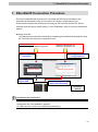
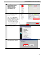
Machine Automation Controller NJ-series
EtherNet/IP
TM
Connection Guide
OMRON Corporation
FZ5-series Vision System
P589-E1-01
About Intellectual Property Rights and Trademarks
Microsoft product screen shots reprinted with permission from Microsoft Corporation.
Windows is a registered trademark of Microsoft Corporation in the USA and other countries.
ODVA and EtherNet/IPTM are trademarks of ODVA.
EtherCATR is registered trademark and patented technology, licensed by Beckhoff Automation
GmbH, Germany.
Sysmac is a trademark or registered trademark of OMRON Corporation in Japan and other
countries for OMRON factory automation products.
Company names and product names in this document are the trademarks or registered
trademarks of their respective companies.
Table of Contents
1.
Related Manuals .......................................................................................... 1
2.
Terms and Definitions................................................................................. 2
3.
Precautions .................................................................................................. 3
4.
Overview ...................................................................................................... 4
5.
Applicable Devices and Device Configuration ........................................ 5
6.
7.
8.
5.1.
Applicable Devices .............................................................................. 5
5.2.
Device Configuration ........................................................................... 6
EtherNet/IP Settings.................................................................................... 8
6.1.
EtherNet/IP Communications Parameters .......................................... 8
6.2.
Data Types for Tag Data Links ............................................................ 8
6.3.
Allocating the Tag Data Links .............................................................. 9
EtherNet/IP Connection Procedure ......................................................... 12
7.1.
Work Flow .......................................................................................... 13
7.2.
Setting Up the FZ5 Sensor Controller ............................................... 14
7.3.
Setting Up the Controller ................................................................... 19
7.4.
Setting Up the Network...................................................................... 25
7.5.
Checking the EtherNet/IP Communications ...................................... 29
Initialization Method.................................................................................. 33
8.1.
Initializing the Controller .................................................................... 33
8.2.
9.
Initializing the FZ5 Sensor Controller ................................................ 35
Appendix 1 Detailed Settings of the Tag Data Links ............................. 36
9.1.
Global Variable Table ......................................................................... 36
9.2.
Relationship between Destination Device and Global Variables ...... 37
9.3.
Associating the Tag Data Links ......................................................... 39
10. Appendix 2 Setting the Tag Data Links Using the Software................. 40
10.1. Overview of Setting Tag Data Links .................................................. 40
10.2.
Work Flow of "Procedure for Setting Parameters from Beginning" .. 41
10.3.
Setting Up the Controller Using the Software ................................... 43
10.4.
Setting Up the Network Using the Software ...................................... 56
11. Revision History ........................................................................................ 66
1.Related Manuals
1. Related Manuals
The table below lists the manuals related to this document.
To ensure system safety, make sure to always read and heed the information provided in all
Safety Precautions, Precautions for Safe Use, and Precaution for Correct Use of manuals for
each device which is used in the system.
Cat. No.
W472
Model
CJ2H-CPU6[]-EIP
Manual name
CJ-series CJ2 CPU Unit Hardware User's Manual
CJ2H-CPU6[]
CJ2M-CPU[][]
W473
CJ2H-CPU6[]-EIP
CJ-series CJ2 CPU Unit Software User's Manual
CJ2H-CPU6[]
CJ2M-CPU[][]
W465
CJ1W-EIP21
EtherNet/IPTMUnit Operation Manual
CJ2H-CPU6[]-EIP
W446
CJ2M-CPU3[]
-
CX-Programmer Operation Manual
Image Processing System Instruction Sheet
9910002-2
FZ5-60[]/60[]-10
FZ5-110[]/110[]-10
FZ5-L35[]/L35[]-10
Z340
FZ5-L35[]
Vision Sensor FH/FZ5 Series Vision System
FZ5-6[][]/11[][]
User's Manual
FZ5-L35[]
Vision Sensor FH/FZ5 Series Vision System
FZ5-6[][]/11[][]
Processing Item Function Reference Manual
FZ5-L35[]
Vision Sensor FH/FZ5 Series Vision System
FZ5-6[][]/11[][]
User's Manual (Communications Settings)
9524422-4
Z341
Z342
Image Processing System Instruction Sheet
1
2.Terms and Definitions
2. Terms and Definitions
Term
Node
Explanation and Definition
Controllers and devices are connected to the EtherNet/IP network via the
EtherNet/IP ports. The EtherNet/IP recognizes each EtherNet/IP port
connected to the network as one node.
When a device with two EtherNet/IP ports is connected to the
EtherNet/IP network, the EtherNet/IP recognizes this device as two
nodes.
The EtherNet/IP achieves the communications between controllers or the
communications between controllers and devices by exchanging data
between these nodes connected to the network.
Tag
A minimum unit of the data that is exchanged on the EtherNet/IP network
is called a tag. The tag is defined as a network variable or as a physical
address, and it is allocated to the memory area of each device.
Tag set
In the EtherNet/IP network, a data unit that consists of two or more tags
can be exchanged. The data unit consisting of two or more tags for the
data exchange is called a tag set. Up to eight tags can be configured per
tag set for OMRON controllers.
Tag data link
In the EtherNet/IP, the tag and tag set can be exchanged cyclically
between nodes without using the user program. This standard feature on
the EtherNet/IP is called a tag data link.
Connection
A connection is used to exchange data as a unit within which data
concurrency is maintained. The connection consists of tags or tag sets.
Creating the concurrent tag data link between the specified nodes is
called a "connection establishment ". When the connection is
established, the tags or tag sets that configure the connection are
exchanged between the specified nodes concurrently.
Originator and
To perform tag data links, one node requests the opening of a
Target
communications line called a "connection".
The node that requests opening the connection is called an "originator",
and the node that receives the request is called a "target".
Tag data link
The tag data link parameter is the setting data to perform the tag data
parameter
link. It includes the data to set tags, tag sets, and connections.
EDS file
A file that describes the number of I/O points for the EtherNet/IP device
and the parameters that can be set via EtherNet/IP.
2
3.Precautions
3. Precautions
(1) Understand the specifications of devices which are used in the system. Allow some
margin for ratings and performance. Provide safety measures, such as installing safety
circuit in order to ensure safety and minimize risks of abnormal occurrence.
(2) To ensure system safety, always read and heed the information provided in all Safety
Precautions, Precautions for Safe Use, and Precaution for Correct Use of manuals for
each device used in the system.
(3) The user is encouraged to confirm the standards and regulations that the system must
conform to.
(4) It is prohibited to copy, to reproduce, and to distribute a part or the whole of this
document without the permission of OMRON Corporation.
(5) The information contained in this document is current as of December 2013. It is subject
to change without notice for improvement.
The following notation is used in this document.
Indicates a potentially hazardous situation which, if not avoided,
will result in minor or moderate injury, or may result in serious
injury or death. Additionally there may be significant property
damage.
Precautions for Correct Use
Precautions on what to do and what not to do to ensure proper operation and performance.
Additional Information
Additional information to read as required.
This information is provided to increase understanding or make operation easier.
Symbol
The filled circle symbol indicates operations that you must do.
The specific operation is shown in the circle and explained in text.
This example shows a general precaution for something that you must do.
3
4.Overview
4. Overview
This document describes the procedure for connecting the Vision System (FZ5 Sensor
Controller + Camera)(FZ5 series) of OMRON Corporation (hereinafter referred to as OMRON)
to NJ-series Machine Automation Controller (hereinafter referred to as the Controller) via
EtherNet/IP and provides the procedure for checking their connection.
It also contains the procedure for performing EtherNet/IP tag data link using the EtherNet/IP
settings of the project file that is prepared beforehand (hereinafter referred to as the
"Procedure for Using the Configuration Files").
Section 9 Appendix 1 and Section 10 Appendix 2 describe the procedures for setting
parameters with software without using files (hereinafter referred to as the "Procedure for
Setting Parameters from Beginning").
To follow the "Procedure for Using the Configuration Files", obtain the latest "Sysmac Studio
project file" and "Network Configurator v3 network configuration file" (they are referred to as
"Configuration Files") from OMRON in advance.
Name
Sysmac Studio project file
(extension: smc2)
Network Configurator v3 network
configuration file (extension: nvf)
File name
Version
OMRON_FZ5_EIP_EV100.smc2
Ver.1.00
OMRON_FZ5_EIP_EV100.nvf
Ver.1.00
4
5.Applicable Devices and Device Configuration
5. Applicable Devices and Device Configuration
5.1. Applicable Devices
The applicable devices are as follows:
Manufacturer
OMRON
NJ-series CPU Unit
Name
OMRON
FZ5 Sensor Controller
Model
NJ501-[][][][]
NJ301-[][][][]
LCD-integrated Controller
FZ5-60[]/60[]-10
FZ5-110[]/110[]-10
Box-type Controller
OMRON
0.3 Megapixel Digital Camera
0.3 Megapixel Small Digital Camera
0.3 Megapixel Small Digital Pen-Shaped Camera
0.3 Megapixel High-Speed Camera
2 Megapixel Digital Camera
5 Megapixel Digital Camera
Intelligent Camera
Intelligent Compact Camera
FZ5-L35[]/L35[]-10
FZ-SC/S
FZ-SFC/SF
FZ-SPC/SP
FZ-SHC/SH
FZ-SC2M/S2M
FZ-SC5M2/S5M2
FZ-SLC100
FZ-SQ010F/SQ050F
FZ-SQ100F/SQ100N
Precautions for Correct Use
As applicable devices above, the devices with the models and versions listed in Section 5.2.
are actually used in this document to describe the procedure for connecting devices and
checking the connection.
You cannot use devices with versions lower than the versions listed in Section 5.2.
To use the above devices with versions not listed in Section 5.2 or versions higher than those
listed in Section 5.2, check the differences in the specifications by referring to the manuals
before operating the devices.
Additional Information
This document describes the procedure to establish the network connection. Except for the
connection procedure, it does not provide information on operation, installation or wiring
method. It also does not describe the functionality or operation of the devices. Refer to the
manuals or contact your OMRON representative.
5
5.Applicable Devices and Device Configuration
5.2. Device Configuration
The hardware components to reproduce the connection procedure of this document are as
follows:
NJ501-1500
(Built-in EtherNet/IP port)
Personal computer
(Sysmac Studio installed,
OS: Windows 7 )
FZ5-L350
LAN
cable
USB cable
Switching hub
W4S1-05C
Manufact
urer
OMRON
USB connected
mouse
Name
FZ-M08
FZ-VS
FZ-SC2M
Model
Version
NJ501-1500
Ver.1.07
NJ-PA3001
W4S1-05C
SYSMAC-SE2[][][]
(Included in Sysmac Studio.)
OMRON_FZ5_EIP_EV100.smc2
OMRON_FZ5_EIP_EV100.nvf
Ver.1.00
Ver.1.08
Ver.3.56
Ver.1.00
Ver.1.00
OMRON
NJ-series CPU Unit
(Built-in EtherNet/IP port)
Power Supply Unit
Switching hub
Sysmac Studio
Network-Configurator
Sysmac Studio project file
Network Configurator v3
network configuration file
Personal computer
(OS: Windows 7)
USB cable
(USB 2.0 type B connector)
LAN cable (STP (shielded,
twisted-pair) cable of Ethernet
category 5 or higher)
FZ5 Sensor Controller
OMRON
Camera
FZ-SC2M
OMRON
Camera cable
FZ-VS
OMRON
-
Monitor (analog RGB monitor)
FZ-M08
USB connected mouse
-
OMRON
OMRON
OMRON
OMRON
OMRON
OMRON
-
-
FZ5-L350
Ver.5.12
Precautions for Correct Use
Prepare the latest "Sysmac Studio project file" and "Network Configurator v3 network
configuration file" from OMRON in advance.
(To obtain the files, contact your OMRON representative.)
6
5.Applicable Devices and Device Configuration
Precautions for Correct Use
Update the Sysmac Studio to the version specified in this section or higher version using the
auto update function.
If a version not specified in this section is used, the procedures described in Section 7 and
subsequent sections may not be applicable. In that case, use the equivalent procedures
described in the Sysmac Studio Version 1 Operation Manual (Cat. No. W504) and Network
Configurator Online Help.
Additional Information
The system configuration in this document uses USB for the connection to the Controller. For
information on how to install a USB driver, refer to A-1 Driver Installation for Direct USB Cable
Connection of the Sysmac Studio Version 1 Operation Manual (Cat. No. W504).
7
6.EtherNet/IP Settings
6. EtherNet/IP Settings
This section describes the specifications such as communication parameters and tag data link
that are set in this document.
Hereinafter, the FZ5 Sensor Controller is referred to as the "Destination Device" in some
descriptions.
6.1. EtherNet/IP Communications Parameters
The communications parameter required connecting the Controller and the Destination
Device via EtherNet/IP is given below.
Controller (node 1)
FZ5 Sensor Controller (node 2)
IP address
192.168.250.1
192.168.250.2
Subnet mask
255.255.255.0
255.255.255.0
6.2. Data Types for Tag Data Links
The following data types are used for the data in the tag data links of the Destination Device.
These data types are set in the "Configuration Files".
■ Definition of the data type to access the signals (Union)
These data types are used to access the control signals and status signals.
Data type name
Data type
U_EIPFlag
UNION
F
BOOL[32]
W
DWORD
■ Definition of the data type to access the command area (Structure)
These data types are used to access the command area.
Data type name
Data type
Destination device data
S_EIPOutput
STRUCT
ControlFlag
U_EIPFlag
Control signal (32 bits)
CommandCode
DWORD
Command code (CMD-CODE)
CommandParam1
DINT
Command parameter
CommandParam2
DINT
(CMD-PARAM)
CommandParam3
DINT
■ Definition of the data type to access the response/output areas (Structure)
These data types are used to access the response/output areas.
Data type name
Data type
Destination device data
S_EIPInput
STRUCT
StatusFlag
U_EIPFlag
Control output (32 bits)
CommandCodeEcho
DWORD
Command code (CMD-CODE)
ResponseCode
DINT
Response code (RES-CODE)
ResponseData
DINT
Response data (RES-DATA)
OutputData
DINT[8]
Output data 0 to 7 (DATA 0 to 7)
8
6.EtherNet/IP Settings
6.3. Allocating the Tag Data Links
The data in the tag data links of the Destination Device is allocated to the global variables of
the Controller. The relationship between the destination device data and the global variables
is shown below.
The following global variables are set in the "Configuration Files".
■ Output area (from Controller to FZ5 Sensor Controller)
Variable
Data type
EIP002_OUT
S_EIPOutput
Offset
+0 to +1
+2 to +3
+4 to +5
+6 to +7
+8 to +9
Data size
20 bytes
Destination device data
Control signal (32 bits)
(Data type: U_EIPFlag)
Command code
(CMD-CODE)
Command parameter
(CMD-PARAM)
Global variable
Data type
EIP002_OUT.ControlFlag.F
*1
BOOL[32]
*1
DWORD
EIP002_OUT.CommandCode
DWORD
EIP002_OUT.CommandParam1
DINT
EIP002_OUT.CommandParam2
DINT
EIP002_OUT.CommandParam3
DINT
EIP002_OUT.ControlFlag.W
*1: Details on allocation of control signal
Allocation of ControlFlag.F
Offset
15
14 13 12 11 10 9
8
7
6
5
4
3
2
1
0
+0 ERCLR **** **** **** **** **** **** XEXE **** **** **** **** **** **** STEP EXE
DSA
+1
EXE: Command Request Bit: Turned ON to execute a command.
STEP: Measure Bit: Turned ON to execute a measurement.
XEXE: Flow Command Request Bit: Turned ON to request execution of a
command during execution of fieldbus flow control.
ERCLR: Error Clear Bit: Turned ON to clear the Error Status bit.
DSA: Data Output Request Bit: Turned ON to request data output.
Allocation of ControlFlag.W.
Offset
+0
15
14
13
・・・
2
1
0
15
14
13
・・・
2
1
0
18 17 16
・・・
+1 31 30 29
Bits 31 to 0: ControlFlag.W uses DWORD data from the offset +0 word.
9
6.EtherNet/IP Settings
■ Input area (from FZ5 Sensor Controller to Controller)
Variable
Data type
EIP002_IN
S_EIPInput
Offset
+0 to +1
+2 to +3
+4 to +5
+6 to +7
+8 to +9
+10 to +11
+12 to +13
+14 to +15
+16 to +17
+18 to +19
+20 to +21
+22 to +23
Data size
48 bytes
Destination device data
Control output (32 bits)
(Data type: U_EIPFlag)
Command code
(CMD-CODE)
Response code
(RES-CODE)
Response data
(RES-DATA)
Output data 0 (DATA0)
Output data 1 (DATA1)
Output data 2 (DATA2)
Output data 3 (DATA3)
Output data 4 (DATA4)
Output data 5 (DATA5)
Output data 6 (DATA6)
Output data 7 (DATA7)
Global variable
EIP002_IN.StatusFlag.F*1
EIP002_IN.StatusFlag.W *1
Data type
BOOL[32]
DWORD
EIP002_IN.CommandCodeEcho
DWORD
EIP002_IN.ResponseCode
DINT
EIP002_IN.ResponseData
DINT
EIP002_IN.OutputData[0] to
EIP002_IN.OutputData[7]
DINT[8]
*1: Details on allocation of control signal
Allocation of StatusFlag.F
Offset
15 14 13 12 11 10
9
8
7 6 5 4 3 2
1
0
+0 ERR **** **** **** **** XWAIT XBUSY XFLG **** **** **** RUN OR **** BUSY FLG
**** ****
GATE
+1 ****
FLG: Command Completion Bit: Turned ON when command execution is completed.
BUSY: Command Busy Bit: Turned ON when command execution is in progress.
OR: Overall Judgement Bit: Turned ON when the overall judgement is NG.
RUN: Run Mode Bit: Turned ON while the Sensor Controller is in Run Mode.
XFLG: Flow Command Completion Bit: Turned ON when execution of a command
that was input during the execution of fieldbus flow control has been
completed (i.e., when XBUSY turns OFF).
XBUSY: Flow Command Busy Bit: Turned ON when execution of a command that
was input during execution of fieldbus flow control is in progress.
XWAIT: Flow Command Wait Bit: Turned ON when a command can be input during
the execution of fieldbus flow control.
ERR: Error Signal: Turned ON when the Sensor Controller detects an error signal.
GATE: Data Output Completion Bit: Turned ON when data output is completed.
Allocation of StatusFlag.W
Offset
+0
15
14
13
・・・
2
1
0
15
14
13
・・・
2
1
0
18 17 16
・・・
+1 31 30 29
Bits 31 to 0: EIPInput.StatusFlag.W uses DWORD data from the offset +0 word.
10
6.EtherNet/IP Settings
Precautions for Correct Use
If the data size in tag data links of the Destination Device is an odd-numbered byte, use
BYTE type to define, but not BOOL type.
Additional Information
For details on the command codes and response codes, refer to Accessing Communications
Areas Using Variables with NJ-series Controllers in Section 2 Methods for Connecting and
Communicating with External Devices - Communicating with EtherNet/IP - Memory Allocation
of the Vision Sensor FH/FZ5 Series Vision System User's Manual (Communications Settings)
(Cat. No. Z342).
Additional Information
With the Sysmac Studio, two methods can be used to specify an array for a data type. After
specifying, (1) is converted to (2) and the data type is always displayed as (2).
(1)WORD[3]/(2)ARRAY[0..2]OF WORD
In this document, the data type is simplified by describing WORD[3].
(The example above means a WORD data type with three array elements.)
11
7.EtherNet/IP Connection Procedure
7. EtherNet/IP Connection Procedure
This section describes the procedure for connecting the FZ5 Sensor Controller to the
Controller via EtherNet/IP using the "Procedure for Using the Configuration Files".
This document explains the procedures for setting up the Controller and the FZ5 Sensor
Controller from the factory default setting. For the initialization, refer to Section 8 Initialization
Method.
■ Setting Overview
The following figure shows the relationship of operating the EtherNet/IP tag data link using
the "Procedure for Using the Configuration Files".
Configuration Files
Sysmac Studio project file
Network Configurator v3
network configuration file
Opening the
project file
Opening the network
configuration file
Personal computer
Sysmac Studio
Transferring the
Project Data
Controller
Network Configurator
Transferring the Tag
Data Link Parameters
Destination
Device
Precautions for Correct Use
Prepare the latest "Sysmac Studio project file" and "Network Configurator v3 network
configuration file" from OMRON in advance.
(To obtain the files, contact your OMRON representative.)
12
7.EtherNet/IP Connection Procedure
7.1. Work Flow
Take the following steps to operate the tag data link for EtherNet/IP.
7.2. Setting Up the FZ5 Sensor
Set up the FZ5 Sensor Controller.
Controller
↓
7.2.1. Parameter Settings
↓
7.3. Setting Up the Controller
↓
7.3.1. Starting the Sysmac Studio and
Importing the Project File
↓
7.3.2. Connecting Online and
Transferring the Project Data
Set the parameters for the FZ5 Sensor Controller.
Set up the Controller.
Start the Sysmac Studio and import the Sysmac
Studio project file.
Connect online with the Sysmac Studio and
transfer the project data to the Controller.
↓
7.4. Setting Up the Network
↓
7.4.1. Starting the Network
Configurator and Opening the
Set the tag data links for the EtherNet/IP.
Start up the Network Configurator and open the
Network Configurator v3 network configuration
file.
Network Configuration File.
↓
7.4.2. Transferring the Tag Data Link
Parameters
Transfer the tag data link parameters to the
Controller.
↓
7.5. Checking the EtherNet/IP
Communications
↓
7.5.1 Checking the Connection Status
↓
7.5.2 Checking the Data that are Sent
and Received
Confirm that the EtherNet/IP tag data links are
operated normally.
Check the connection status of EtherNet/IP.
Confirm that the correct data are sent and
received.
13
7.EtherNet/IP Connection Procedure
7.2. Setting Up the FZ5 Sensor Controller
Set up the FZ5 Sensor Controller.
7.2.1. Parameter Settings
Set the parameters for the FZ5 Sensor Controller.
1
Connect the Camera, Monitor,
USB connected mouse, and the
LAN cable to the FZ5 Sensor
Controller.
Connect the LAN cable at the
other end to the Switching hub.
Connect the power supply cable
to the Power terminal.
2
Turn ON the power supply to the
3
The Language setting Dialog
FZ5 Sensor Controller.
Box is displayed on the Monitor
connected to the FZ5 Sensor
Controller only at the initial start.
Select English and click the OK
Button.
Confirm that your desired
Language is selected and click
the Yes Button.
4
Select System Settings from
the Tool Menu in the FZ-PanDA
Dialog Box on the Monitor.
14
7.EtherNet/IP Connection Procedure
5
Select System
Settings-Startup-Startup
setting from the tree.
The setting dialog box is
displayed. Select the
Communication Tab.
6
The Communication module
select Dialog Box is displayed.
Select EtherNet/IP from the
Fieldbus pull-down list.
Then, click the Apply Button.
Click the Close Button to close
the System Settings Dialog Box.
7
8
* The data set in the System
Settings Dialog Box as shown
on the right becomes enabled
after the settings are saved,
and then the FZ5 Sensor
Controller is restarted.
Select Data save from the
Function Menu.
The Data save Dialog Box is
displayed. Click the OK Button.
15
7.EtherNet/IP Connection Procedure
9
10
Select System restart from the
Function Menu.
The System restart Dialog Box
is displayed. Check the contents
and click the OK Button.
11
After restarting, select System
12
Select System Settings -
Settings from the Tool Menu.
Communication Ethernet:Normal(UDP) from
the tree.
16
7.EtherNet/IP Connection Procedure
13
The dialog box on the right is
displayed. Select the Use the
following IP address Option for
Address setting and set the
following values.
IP address: 192.168.250.2
Subnet Mask: 255.255.255.0
* How to change values.
* To change a value, click the
Button in the item in which a
value is to be set. The numeric
keyboard is displayed. Enter
values using the mouse.
After entering the values, click
the OK Button on the numeric
keyboard.
17
7.EtherNet/IP Connection Procedure
14
When a value is changed, the
Apply Button is displayed. Click
the Apply Button.
While the setting is being
processed, the dialog box on the
right is displayed.
After the dialog box disappears,
click the Close Button to close
the System Settings Dialog Box.
15
In the same way as steps 7 and
8, select Data save from the
Function Menu.
16
In the same way as steps 9 and
10, select System restart from
the Function Menu.
18
7.EtherNet/IP Connection Procedure
7.3. Setting Up the Controller
Set up the Controller.
7.3.1. Starting the Sysmac Studio and Importing the Project File
Start the Sysmac Studio and import the Sysmac Studio project file.
Install the Sysmac Studio and USB driver in the Personal computer beforehand.
1
Connect the LAN cable to the
Built-in EtherNet/IP port
CPU Unit
Controller
End cover
(PORT1) of the Controller and
the USB cable to the peripheral
USB cable
Switching hub
(USB) port. Then connect the
Controller, Personal computer,
and Switching hub by referring
Power Supply Unit
DUT
LAN cable
to 5.2. Device Configuration.
2
Turn ON the power supply to the
3
Start the Sysmac Studio.
Controller and Switching hub.
Click the Import Button.
* If a confirmation dialog for an
access right is displayed at
start, select to start.
4
The Import file Dialog Box is
displayed.
Select
OMRON_FZ5_EIP_EV100.smc
2 (Sysmac Studio project file)
and click the Open Button.
* Obtain the Sysmac Studio
project file from OMRON.
19
7.EtherNet/IP Connection Procedure
5
The OMRON_FZ5_EIP_EV100
project is displayed.
The left pane is called Multiview
Explorer, the right pane is called
Toolbox and the middle pane is
called Edit Pane.
Multiview
Explorer
Edit Pane
Toolbox
* If an error message is
displayed stating "Failed to
Load Descendants", change
the version of the Sysmac
Studio to the version specified
in 5.2. Device Configuration or
higher version.
6
7
Select Check All Programs
from the Project Menu.
The Build Tab Page is displayed
on the Edit Pane.
Confirm that "0 Errors" and "0
Warnings" are displayed.
8
9
Select Rebuild Controller from
the Project Menu.
A confirmation dialog box is
displayed. Confirm that there is
no problem and click the Yes
Button.
10
Confirm that "0 Errors" and "0
Warnings" are displayed in the
Build Tab Page.
20
7.EtherNet/IP Connection Procedure
7.3.2. Connecting Online and Transferring the Project Data
Connect online with the Sysmac Studio and transfer the project data to the Controller.
Always confirm safety at the Destination Device before you transfer a user
program, configuration data, setup data, device variables, or values in memory
used for CJ-series Units from the Sysmac Studio.
The devices or machines may perform unexpected operation regardless of the
operating mode of the CPU Unit.
1
2
Select Change Device from the
Controller Menu.
The Change Device Dialog Box
is displayed.
Confirm that the Device and
Version Fields are set as shown
on the right.
* If the settings are different,
select the setting items from the
pull-down list.
Click the OK Button.
3
If you changed the settings in
step 2, the Build Dialog Box is
displayed. Check the contents
and click the Yes Button.
4
Select Communications Setup
from the Controller Menu.
21
7.EtherNet/IP Connection Procedure
5
The Communications Setup
Dialog Box is displayed.
Confirm that the Direct
connection via USB Option is
selected for Connection type.
Click the OK Button.
6
Select Online from the
Controller Menu.
* If the dialog on the right is
displayed, the model or version
*Example of confirmation dialog box
of the Controller does not match
that of the project file. Match the
Controller model and version by
changing the device settings of
the project file, and then repeat
the procedure from step 1 in
this section. Close the dialog
box by clicking the OK Button.
* The model and version
displayed on the confirmation
dialog box differ depending on
the Controller used and the
device setting of the project file.
Additional Information
For details on online connections to a Controller, refer to Section 5 Online Connections to a
Controller of the Sysmac Studio Version 1 Operation Manual (Cat. No. W504).
22
7.EtherNet/IP Connection Procedure
7
A confirmation dialog box is
displayed as shown on the right.
Confirm that there is no problem
and click the Yes Button.
* The displayed dialog depends
on the status of the Controller
used. Click the Yes Button to
proceed with the processing.
* The displayed serial ID differs
depending on the device.
8
When an online connection is
established, a yellow bar is
displayed on the top of the Edit
Pane.
9
10
Select Synchronization from
the Controller Menu.
The Synchronization Dialog Box
is displayed.
Confirm that the data to transfer
(NJ501 in the right dialog) is
selected. Then, click the
Transfer To Controller Button.
* After executing the Transfer To
Controller, the Sysmac Studio
data is transferred to the
Controller and the data is
compared.
23
7.EtherNet/IP Connection Procedure
11
A confirmation dialog box is
displayed. Confirm that there is
no problem and click the Yes
Button.
A screen stating "Synchronizing"
is displayed.
A confirmation dialog box is
displayed. Confirm that there is
no problem and click the No
Button.
* Do not return it to RUN mode.
12
Confirm that the synchronized
data is displayed with the color
specified by "Synchronized",
and that a message is displayed
stating "The synchronization
process successfully finished".
If there is no problem, click the
Close Button.
* A message stating "The
synchronization process
successfully finished" is
displayed if the Sysmac Studio
project data and the data in the
Controller match.
* If the synchronization fails,
check the wiring and repeat
from step 1.
24
7.EtherNet/IP Connection Procedure
7.4. Setting Up the Network
Set the tag data links for the EtherNet/IP.
7.4.1. Starting the Network
Configuration File
Configurator
and
Opening
the
Network
Start up the Network Configurator and open the Network Configurator v3 network
configuration file.
Precautions for Correct Use
Confirm that the LAN cable is connected before taking the following procedure.
When it is not connected, turn OFF the power supply to each device and then connect the
LAN cable.
1
Start the Network Configurator.
Hardware List
2
Select Open from the File Menu.
3
The Open Dialog Box is
Network Configuration
displayed.
Select
OMRON_FZ5_EIP_EV100.nvf
(Network Configurator v3
network configuration file) and
click the Open Button.
* Obtain the Network
Configurator v3 network
configuration file from OMRON.
25
7.EtherNet/IP Connection Procedure
4
The following devices are
displayed in the Network
Configuration Pane as shown on
the right.
IP address of node 1:
192.168.250.1
IP address of node 2:
192.168.250.2
* The destination device icon
changes to the FZ Series
device.
5
Select Select Interface - NJ
Series USB Port from the
Option Menu.
6
Select Connect from the
7
The Select Connect Network
Network Menu.
Port Dialog Box is displayed.
Select TCP:2.
Click the OK Button.
26
7.EtherNet/IP Connection Procedure
8
The Select Connected Network
Dialog Box is displayed. Check
the contents and click the OK
Button.
9
When an online connection is
established normally, the color
of the icon on the right figure
changes to blue.
Additional Information
If an online connection cannot be made to the Controller, check the cable connection. Or,
return to step 4, check the settings and repeat each step.
For details, refer to 7.2.8 Connecting the Network Configurator to the Network in Section 7
Tag Data Link Functions of the NJ-series CPU Unit Built-in EtherNet/IP Port User's Manual
(Cat. No. W506).
27
7.EtherNet/IP Connection Procedure
7.4.2. Transferring the Tag Data Link Parameters
Transfer the tag data link parameters to the Controller.
1
Right-click the device icon of
node 1 on the Network
Configuration Pane and select
Parameter - Download.
The dialog box on the right is
displayed. Confirm that there is
no problem and click the Yes
Button.
2
Tag data link parameters are
downloaded from the Network
Configurator to the Controller.
3
The dialog box on the right is
displayed. Check the contents
and click the OK Button.
28
7.EtherNet/IP Connection Procedure
7.5. Checking the EtherNet/IP Communications
Confirm that the EtherNet/IP tag data links are operated normally.
7.5.1. Checking the Connection Status
Check the connection status of EtherNet/IP.
1
Confirm that the tag data links are
normally in operation by checking
the LED indicators on each device.
・Controller (Built-in EtherNet/IP
port)
The LED indicators in normal
status are as follows:
[NET RUN]: Lit green
[NET ERR]: Not lit
[LINK/ACT]: Flashing yellow
(Flashing while packets are being
(Controller)
sent and received)
2
Confirm that the tag data links are
normally in operation by checking
the status information on the
Monitor Device Window of the
Network Configurator.
Right-click the device icon of node 1
on the Network Configuration Pane
and select Monitor.
29
7.EtherNet/IP Connection Procedure
3
The dialog box on the right displays
the Status 1 Tab Page of the Device
Monitor Dialog Box.
When the same items as shown on
the right are selected in the Data
Link Status Field, the data links are
normally in operation.
* The Tag Data Link Check Box in
the Ethernet Status Field can not be
checked shortly after tag data link
Number: Node number
Blue: Connection normal
parameters have been transferred.
Click the Close Button.
4
Select Disconnect from the
Network Menu to go offline.
5
The color of the icon on the figure
6
Select Exit from the File Menu to
changes from blue.
exit the Network Configurator.
30
7.EtherNet/IP Connection Procedure
7.5.2. Checking the Data that are Sent and Received
Confirm that the correct data are sent and received.
Always confirm safety at the Destination Device before you transfer a user
program, configuration data, setup data, device variables, or values in memory
used for CJ-series Units from the Sysmac Studio.
The devices or machines may perform unexpected operation regardless of the
operating mode of the CPU Unit.
1
Select Watch Tab Page from the
2
The Watch Window1 Tab Page is
View Menu.
displayed in the lower section of the
Edit Pane.
3
The following names are entered in
the Watch Window1 Tab Page for
monitoring.
EIP002_OUT.ControlFlag.F[0]:
Command Request Bit (EXE)
EIP002_OUT.CommandCode:
Command code (CMD-CODE)
EIP002_IN.StatusFlag.F[0]:
Command Completion Bit (FLG)
EIP002_IN.CommandCodeEcho:
Command code (CMD-CODE)
EIP002_IN.ResponseCode:
Response code (RES-CODE)
31
7.EtherNet/IP Connection Procedure
4
Enter 00101010 in the Modify
Column of
EIP002_OUT.CommandCode.
(CommandCode [00101010]:
Measurement)
By pressing the Enter Key, the
value is set and the Online value of
EIP002_OUT.CommandCode
changes to 00101010.
Click TRUE in the Modify Column of
EIP002_OUT.ControlFlag.F[0].
The Online value changes to True.
(EIPOutput.ControlFlag.F[0]:
Command Request Bit)
5
After the measurement is
completed, OK is displayed on the
dialog box.
6
The execution results are reflected
in the following variables.
・EIP002_IN.StatusFlag.F[0]: True
(It returns to False after a certain
time)
・EIP002_IN.CommandCodeEcho:
00101010
(The sent command code is
returned)
・EIP002_IN.ResponseCode: 0
(The execution result of the
command (0: OK, -1: NG))
32
8.Initialization Method
8. Initialization Method
This document explains the setting procedure from the factory default setting.
Some settings may not be applicable as described in this document unless you use the
devices with the factory default setting.
8.1. Initializing the Controller
To initialize the settings of the Controller, the CPU Unit and EtherNet/IP port need to be
initialized. Change the Controller to PROGRAM mode before the initialization.
8.1.1. EtherNet/IP port
Delete the connection information and tag information that are set for the EtherNet/IP port.
Follow the procedure below to set blank connection information and blank tag information
and delete them using the Network Configurator.
(1) Deleting connection information
Select the Connections Tab of the Edit Device Parameters Dialog Box and move all
devices registered in the Register Device List Field to the Unregister Device List Field.
If a confirmation dialog is displayed when you remove devices from the registration list,
click the Yes Button.
No registered
devices
33
8.Initialization Method
(2) Deleting tag information
Select the Tag Sets Tab of the Edit Device Parameters Dialog Box and click the Delete all
of unused Tag Sets Button.
If a confirmation dialog is displayed when you delete tag sets from the registration list,
confirm that there is no problem and click the Yes Button.
No registered
tags
(3) Download
Right-click the Controller and select Parameter - Download from the menu that is
displayed.
34
8.Initialization Method
8.1.2. CPU Unit
To initialize the settings of the CPU Unit, select Clear All Memory from the Controller
Menu of the Sysmac Studio. The Clear All Memory Dialog Box is displayed. Check the
contents and click the OK Button.
8.2. Initializing the FZ5 Sensor Controller
For how to initialize the FZ5 Sensor Controller, refer to Initializing the Controller in Section 1 Before
Operation of the Vision Sensor FH/FZ5 Series Vision System User's Manual (Cat.No.Z340).
35
9.Appendix 1 Detailed Settings of the Tag Data Links
9. Appendix 1 Detailed Settings of the Tag Data Links
This section provides the detailed settings necessary to perform tag data links which are set in
this document.
9.1. Global Variable Table
The Controller accesses the data in tag data links as global variables. The following are the
settings of the global variables. Use the Sysmac Studio to register a global variable table.
EIP002_OUT
S_EIPOutput
Output
Destination device
allocation
Output data (20Bytes)
EIP002_IN
S_EIPInput
Input
Input data (48Bytes)
Name
Data type
Network publish
* For details on data types, refer to 6.2 Data Types for Tag Data Links.
Precautions for Correct Use
If the data size in tag data links of the Destination Device is an odd-numbered byte, use
BYTE type to define, but not BOOL type.
Additional Information
For details on the command codes and response codes, refer to Accessing Communications
Areas Using Variables with NJ-series Controllers in Section 2 Methods for Connecting and
Communicating with External Devices - Communicating with EtherNet/IP - Memory Allocation
of the Vision Sensor FH/FZ5 Series Vision System User's Manual (Communications Settings)
(Cat. No. Z342).
Additional Information
With the Sysmac Studio, two methods can be used to specify an array for a data type. After
specifying, (1) is converted to (2) and the data type is always displayed as (2).
(1)WORD[3]/(2)ARRAY[0..2]OF WORD
In this document, the data type is simplified by describing WORD[3].
(The example above means a WORD data type with three array elements.)
36
9.Appendix 1 Detailed Settings of the Tag Data Links
9.2. Relationship between Destination Device and Global Variables
Global variables need to be arranged in offset order of the Destination Device before setting
the tag data link parameters. The order of offset is the same as that of described in 6.2. Data
Types for Tag Data Links.
The relationship between the memory allocation of the Destination Device and the global
variables is shown below.
■ Output area (from Controller to FZ5 Sensor Controller)
Variable
Data type
EIP002_OUT
S_EIPOutput
Offset
+0 to +1
+2 to +3
+4 to +5
+6 to +7
+8 to +9
Data size
20 bytes
Destination device data
Control signal (32 bits)
(Data type: U_EIPFlag)
Command code
(CMD-CODE)
Command parameter
(CMD-PARAM)
Global variable
Data type
EIP002_OUT.ControlFlag.F
*1
BOOL[32]
*1
DWORD
EIP002_OUT.CommandCode
DWORD
EIP002_OUT.CommandParam1
DINT
EIP002_OUT.CommandParam2
DINT
EIP002_OUT.CommandParam3
DINT
EIP002_OUT.ControlFlag.W
*1: Details on allocation of control signal
Allocation of ControlFlag.F
Offset (word)
15
14 13 12 11 10 9
8
7
6
5
4
3
2
1
0
+0 ERCLR **** **** **** **** **** **** XEXE **** **** **** **** **** **** STEP EXE
DSA
+1
EXE: Command Request Bit: Turned ON to execute a command.
STEP: Measure Bit: Turned ON to execute a measurement.
XEXE: Flow Command Request Bit: Turned ON to request execution of a command
during execution of fieldbus flow control.
ERCLR: Error Clear Bit: Turned ON to clear the Error Status bit.
DSA: Data Output Request Bit: Turned ON to request data output.
Allocation of ControlFlag.W
Offset
+0
15
14
13
・・・
2
1
0
15
14
13
・・・
2
1
0
・・・
18 17 16
+1 31 30 29
Bits 31 to 0: ControlFlag.W uses DWORD data from the offset +0 word.
37
9.Appendix 1 Detailed Settings of the Tag Data Links
■ Input area (from FZ5 Sensor Controller to Controller)
Variable
Data type
EIP002_IN
S_EIPInput
Offset
+0 to +1
+2 to +3
+4 to +5
+6 to +7
+8 to +9
+10 to +11
+12 to +13
+14 to +15
+16 to +17
+18 to +19
+20 to +21
+22 to +23
Data size
48 bytes
Destination device data
Control output (32 bits)
(Data type: U_EIPFlag)
Command code
(CMD-CODE)
Response code
(RES-CODE)
Response data
(RES-DATA)
Output data 0 (DATA0)
Output data 1 (DATA1)
Output data 2 (DATA2)
Output data 3 (DATA3)
Output data 4 (DATA4)
Output data 5 (DATA5)
Output data 6 (DATA6)
Output data 7 (DATA7)
Global variable
EIP002_IN.StatusFlag.F*1
EIP002_IN.StatusFlag.W *1
Data type
BOOL[32]
DWORD
EIP002_IN.CommandCodeEcho
DWORD
EIP002_IN.ResponseCode
DINT
EIP002_IN.ResponseData
DINT
EIP002_IN.OutputData[0] to
EIP002_IN.OutputData[7]
DINT[8]
*1: Details on allocation of control signal
Allocation of StatusFlag.F
Offset
15 14 13 12 11 10
9
8
7 6 5 4 3 2
1
0
+0 ERR **** **** **** **** XWAIT XBUSY XFLG **** **** **** RUN OR **** BUSY FLG
**** ****
GATE
+1 ****
FLG: Command Completion Bit: Turned ON when command execution is completed.
BUSY: Command Busy Bit: Turned ON when command execution is in progress.
OR: Overall Judgement Bit: Turned ON when the overall judgement is NG.
RUN: Run Mode Bit: Turned ON while the Sensor Controller is in Run Mode.
XFLG: Flow Command Completion Bit: Turned ON when execution of a command
that was input during the execution of fieldbus flow control has been
completed (i.e., when XBUSY turns OFF).
XBUSY: Flow Command Busy Bit: Turned ON when execution of a command that
was input during execution of fieldbus flow control is in progress.
XWAIT: Flow Command Wait Bit: Turned ON when a command can be input during
the execution of fieldbus flow control.
ERR: Error Signal: Turned ON when the Sensor Controller detects an error signal.
GATE: Data Output Completion Bit: Turned ON when data output is completed.
Allocation of StatusFlag.W
Offset
+0
15
14
13
・・・
2
1
0
15
14
13
・・・
2
1
0
18 17 16
・・・
+1 31 30 29
Bits 31 to 0: EIPInput.StatusFlag.W uses DWORD data from the offset +0 word.
38
9.Appendix 1 Detailed Settings of the Tag Data Links
9.3. Associating the Tag Data Links
Tag data link parameters are required to perform tag data links with a Destination Device.
Follow the procedures below to associate the tag data links.
(1) Use the Sysmac Studio to define the global variables to publish on the network.
Store the created global variables in a CSV file to use in the Network Configurator.
(2) Read the CSV file (tag list) created in step (1) to the Network Configurator.
(3) Install the EDS file for the Destination Device in the Network Configurator.
(4) Make a single tag set that includes the tag lists.
(5) Link the tag set with the destination device information and create tag data link
parameters.
The numbers shown in the tables below correspond to the steps above.
■ Output area (from Controller to FZ5 Sensor Controller)
Controller setting
Data link table setting
(Set with Sysmac Studio.)
(Set with Network Configurator.)
Tag set:
20Byte
(1)
EIP002_OUT
(4)
Global variable (Data type)
(3) Tag list
EIP002_OU
=>
S_EIPOutput
T
(2)
EIP002_OUT
(20Byte)
■ Input area (from FZ5 Sensor Controller to Controller)
Controller setting
Data link table setting
(Set with Sysmac Studio.)
(Set with Network Configurator.)
Tag set:
48Byte
(1)
EIP002_IN
(4)
Global variable (Data type)
(3) Tag list
EIP002_IN
S_EIPInput
=>
(2)
EIP002_IN
<=
Destination device
information
Output_100-[20Byte]
<=
Destination device
information
Input_101-[48Byte]
(48Byte)
39
10.Appendix 2 Setting the Tag Data Links Using the Software
10. Appendix 2 Setting the Tag Data Links Using the
Software
This section describes the procedure for setting the Controller without the Configuration Files
(Procedure for Setting Parameters from Beginning).
You can also refer to this section to change parameter settings of the Configuration Files.
10.1. Overview of Setting Tag Data Links
The following figure shows the relationship of operating the tag data links using the
"Procedure for Setting Parameters from Beginning".
Settings made with Network Configurator
Settings made with Sysmac Studio
・Uploading network configuration
・Setting parameters (IP address, etc.)
・Importing CSV file (tag name)
・Setting and exporting global variables
・Tag registration
(name, network setting and task setting, etc.)
・Connection setting (associating tags with
・Building
the EDS file of Destination Device)
・Settings in the Watch Window Tab Page
Personal computer
Global variable
(CSV file)
Sysmac Studio
Transferring the
Project Data
Controller
Network Configurator
Transferring the
Tag Data Link
Parameters
Destination
Device
40
10.Appendix 2 Setting the Tag Data Links Using the Software
10.2. Work Flow of "Procedure for Setting Parameters from Beginning"
Take the following steps to make the tag data link settings for EtherNet/IP using the
"Procedure for Setting Parameters from Beginning"
10.3. Setting Up the Controller Using the Software and 10.4. Setting Up the Network Using the
Software (in red frames below) explain the connection procedures by setting with the software
in stead of using the Configuration Files.
The proceeding for the "Procedure for Using the Configuration Files" described in 7.2. Setting
Up the FZ5 Sensor Controller and 7.5. Checking the EtherNet/IP Communications applies to
those of "Procedure for Setting Parameters from Beginning". Refer to the procedures in
Section 7.
7.2. Setting Up the FZ5 Sensor
Set up the FZ5 Sensor Controller.
Controller
↓
7.2.1. Parameter Settings
↓
10.3. Setting Up the Controller Using
Set the parameters for the FZ5 Sensor Controller.
Set up the Controller using the software.
the Software
↓
10.3.1. Starting the Sysmac Studio and
Setting the Parameters for the
Start the Sysmac Studio and set the parameters for
the Controller.
Controller
↓
10.3.2. Setting and Exporting the
Global Variables
↓
10.3.3. Connecting Online and
Transferring the Project Data
↓
10.3.4. Settings in the Watch Window
Tab Page
Set the global variables and data types to use for the
tag data links.
Connect online with the Sysmac Studio and transfer
the project data to the Controller.
Make settings in the Watch Window Tab Page to
check the data that is sent and received.
↓
41
10.Appendix 2 Setting the Tag Data Links Using the Software
10.4. Setting Up the Network Using the
Software
↓
10.4.1. Start the Network Configurator
and Uploading Configuration
↓
10.4.2. Importing the File and
Registering the Tags
↓
10.4.3. Setting the Connection
↓
10.4.4. Transferring the Tag Data Link
Parameters
Set the tag data links for EtherNet/IP using the
software.
Start the Network Configurator and upload the
network configuration.
Import the CSV file that you saved with the Sysmac
Studio, and register tags of originator's send /receive
areas as well as tag sets.
Associate the tags of the target device with the tags
of the originator.
Transfer the set tag data link parameters to the
Controller.
↓
7.5. Checking the EtherNet/IP
Communications
Confirm that the EtherNet/IP tag data links are
operated normally.
↓
7.5.1 Checking the Connection Status
Check the connection status of EtherNet/IP.
↓
7.5.2 Checking the Data that are Sent
Confirm that the correct data are sent and received.
and Received
42
10.Appendix 2 Setting the Tag Data Links Using the Software
10.3. Setting Up the Controller Using the Software
Set up the Controller using the software.
10.3.1. Starting the Sysmac Studio and Setting the Parameters for the
Controller
Start the Sysmac Studio and set the parameters for the Controller.
Install the Sysmac Studio and USB driver in the Personal computer beforehand.
1
Connect the LAN cable and the
USB cable to the Controller.
* For details, refer to step 1 of
CPU Unit
Controller
End cover
USB cable
Switching hub
7.3.1. Starting the Sysmac
Studio and Importing the Project
File.
2
Turn ON the power supply to the
3
Start the Sysmac Studio.
Power Supply Unit
DUT
LAN cable
Controller and Switching hub.
Click the New Project Button.
* If a confirmation dialog for an
access right is displayed at
start, select to start.
43
10.Appendix 2 Setting the Tag Data Links Using the Software
3
The Project Properties Dialog
Box is displayed.
* In this document, New Project
is used as the Project name.
Confirm that the device you use
is shown in the Category and
Device Fields of Select Device.
Select version 1.07 from the
pull-down list of Version.
* Although 1.07 is selected in
this document for example,
select the version you actually
use.
4
Click the Create Button.
5
The New Project is displayed.
The left pane is called Multiview
Explorer, the right pane is called
Toolbox and the middle pane is
called Edit Pane.
Multiview
Explorer
Edit Pane
Toolbox
44
10.Appendix 2 Setting the Tag Data Links Using the Software
6
Double-click Built-in
EtherNet/IP Port Settings
under Configurations and
Setup - Controller Setup in the
Multiview Explorer.
7
The Built-in EtherNet/IP Port
Settings Tab Page is displayed
in the Edit Pane.
Confirm that the following
settings are made in the IP
Address Field.
IP address: 192.168.250.1
Subnet mask: 255.255.255.0
45
10.Appendix 2 Setting the Tag Data Links Using the Software
10.3.2. Setting and Exporting the Global Variables
Set the global variables and data types to use for the tag data links.
Export the global variables in a CSV file to use as tags in the Network Configurator.
1
Double-click Data Types under
Programming - Data in the
Multiview Explorer.
2
The Data types Tab Page is
displayed in the Edit Pane.
Select the Union Tab.
Click a Name Column to enter a
new data type.
Enter U_EIPFlag in the Name
Column.
3
While the Base Type Column is
being selected, right-click and
select Create New Member
4
from the menu.
The Down Arrow Button is
displayed, allowing you to enter
a new member.
Enter F in the Name Column.
Enter BOOL[32] in the Base
Type Column.
After entering, confirm that the
Base Type changes to
ARRAY[0..31] OF BOOL.
46
10.Appendix 2 Setting the Tag Data Links Using the Software
5
In the same way as steps 3 and
4, enter the following data in the
new columns.
・Name: W
Base Type: DWORD
6
Select the Structures Tab.
Click a Name Column to enter a
new base type.
Enter S_EIPOutput in the Name
Column.
7
While the Base Type Column is
being selected, right-click and
select Create New Member
8
9
from the menu.
The Down Arrow Button is
displayed, allowing you to enter
a new member.
In the same way as step 4, enter
the following data in the new
columns.
・Name: ControlFlag
Base Type: U_EIPFlag
In the same way as steps 7 and
8, enter the following data in the
new member columns.
・Name: CommandCode
Base Type: DWORD
・Name: CommandParam1
Base Type: DINT
・Name: CommandParam2
Base Type: DINT
・Name: CommandParam3
Base Type: DINT
10
Right-click and select Create
11
Enter S_EIPInput in the Name
* Make sure that members are displayed in order of the
offsets listed in Section 9.2.
New Data Type from the menu.
Column.
47
10.Appendix 2 Setting the Tag Data Links Using the Software
12
In the same way as steps 7 and
8, enter the following data in the
new member columns.
・Name: StatusFlag
Base Type: U_EIPFlag
・Name: CommandCodeEcho
Base Type: DWORD
・Name: ResponseCode
Base Type: DINT
・Name: ResponseData
Base Type: DINT
・Name: OutputData
Base Type: DINT [8]
* Make sure that members are displayed in order of the
offsets listed in Section 9.2.
13
Double-click Global Variables
under Programming - Data in
the Multiview Explorer.
14
The Global Variables Tab Page
is displayed in the Edit Pane.
Click a column under the Name
Column to enter a new variable.
Enter EIP002_OUT in the Name
Column.
Enter S_EIPOutput in the Data
Type Column.
Select Output from the Network
Publish Menu.
15
After entering, right-click and
select Create New from the
menu.
48
10.Appendix 2 Setting the Tag Data Links Using the Software
16
In the same way as step 14,
enter the following data in the
new columns.
・Name: EIP002_IN
Data Type: S_EIPInput
Network Publish: Input
17
Select Export Global Variables
- Network Configurator from
the Tools Menu.
18
The Save As Dialog Box is
displayed. Enter EIP002 in the
File name Field.
Click the Save Button.
19
Double-click Task Settings
under Configurations and
Setup in the Multiview Explorer.
The Task Settings Tab Page is
displayed in the Edit Pane. Click
the VAR Button.
Click the + Button.
20
Click the Down Arrow Button of
the Variable to be refreshed
Field. The variables set in steps
14 to 16 are displayed.
Select EIP002_OUT.
21
Click the + Button.
49
10.Appendix 2 Setting the Tag Data Links Using the Software
22
New columns appear. In the
same way as step 20, add the
same variable as you set in step
16 to the Variable to be
refreshed Field.
* Since the data types are
displayed automatically, you do
not have to set them.
Confirm that all variables set in
steps 14 to 16 as shown on the
right are displayed.
50
10.Appendix 2 Setting the Tag Data Links Using the Software
10.3.3. Connecting Online and Transferring the Project Data
Connect online with the Sysmac Studio and transfer the project data to the Controller.
Always confirm safety at the Destination Device before you transfer a user
program, configuration data, setup data, device variables, or values in memory
used for CJ-series Units from the Sysmac Studio.
The devices or machines may perform unexpected operation regardless of the
operating mode of the CPU Unit.
1
Select Check All Programs
from the Project Menu.
2
The Build Tab Page is displayed
on the Edit Pane.
Confirm that "0 Errors" and "0
3
4
Warnings" are displayed.
Select Rebuild Controller from
the Project Menu.
A confirmation dialog box is
displayed. Check the contents
and click the Yes Button.
5
Confirm that "0 Errors" and "0
Warnings" are displayed in the
Build Tab Page.
6
Select Communications Setup
from the Controller Menu.
51
10.Appendix 2 Setting the Tag Data Links Using the Software
7
The Communications Setup
Dialog Box is displayed.
Confirm that the Direct
connection via USB Option is
selected for Connection type.
Click the OK Button.
8
Select Online from the
Controller Menu.
A confirmation dialog box is
displayed. Check the contents
and click the Yes Button.
* The displayed dialog depends
on the status of the Controller
used. Check the contents and
click the Yes Button to proceed
with the processing.
9
When an online connection is
established, a yellow bar is
displayed on the top of the Edit
Pane.
Additional Information
For details on online connections to a Controller, refer to Section 5 Online Connections to a
Controller of the Sysmac Studio Version 1 Operation Manual (Cat. No. W504).
10
Select Synchronization from
the Controller Menu.
52
10.Appendix 2 Setting the Tag Data Links Using the Software
11
The Synchronization Dialog Box
is displayed.
Confirm that the data to transfer
(NJ501 in the right dialog) is
selected. Then, click the
Transfer To Controller Button.
* After executing the Transfer To
Controller, the Sysmac Studio
data is transferred to the
Controller and the data is
compared.
12
A confirmation dialog box is
displayed. Confirm that there is
no problem and click the Yes
Button.
A screen stating "Synchronizing"
is displayed.
A confirmation dialog box is
displayed. Confirm that there is
no problem and click the No
Button.
* Do not return it to RUN mode.
53
10.Appendix 2 Setting the Tag Data Links Using the Software
13
Confirm that the synchronized
data is displayed with the color
specified by "Synchronized",
and that a message is displayed
stating "The synchronization
process successfully finished".
If there is no problem, click the
Close Button.
* A message stating "The
synchronization process
successfully finished" is
displayed if the Sysmac Studio
project data and the data in the
Controller match.
* If the synchronization fails,
check the wiring and repeat from
step 1.
54
10.Appendix 2 Setting the Tag Data Links Using the Software
10.3.4. Settings in the Watch Window Tab Page
Make settings in the Watch Window Tab Page to check the data that is sent and received.
1
2
Select Watch Tab Page from the
View Menu.
The Watch Window1 Tab Page is
displayed in the lower section of the
Edit Pane.
3
Enter the following names in the
Watch Window1 Tab Page for
monitoring.
Click a column under the Name
Column to enter a new name.
EIP002_OUT.ControlFlag.F[0]
EIP002_OUT.CommandCode
EIP002_IN.StatusFlag.F[0]
EIP002_IN.CommandCodeEcho
EIP002_IN.ResponseCode
* You will use the settings in 7.5.2.
Checking the Data That are Sent
and Received.
55
10.Appendix 2 Setting the Tag Data Links Using the Software
10.4. Setting Up the Network Using the Software
Set the tag data links for EtherNet/IP using the software.
10.4.1. Starting the Network Configurator and Uploading the Configuration
Start the Network Configurator and upload the network configuration.
Precautions for Correct Use
Confirm that the LAN cable is connected before taking the following procedure.
When it is not connected, turn OFF the power supply to each device and then connect the
LAN cable.
1
Start the Network Configurator.
Hardware List
Network Configuration Pane
2
Select Select Interface - NJ
Series USB Port from the
Option Menu.
3
Select Connect from the
Network Menu.
56
10.Appendix 2 Setting the Tag Data Links Using the Software
4
The Select Connect Network
Port Dialog Box is displayed.
Select TCP:2.
Click the OK Button.
5
The Select Connected Network
Dialog Box is displayed. Check
the contents and click the OK
Button.
6
When an online connection is
established normally, the color
of the icon on the right figure
changes to blue.
Additional Information
If an online connection cannot be made to the Controller, check the cable connection. Or,
return to step 1, check the settings and repeat each step.
For details, refer to 7-2-8 Connecting the Network Configurator to the Network in Section 7
Tag Data Link Functions of the NJ-series CPU Unit Built-in EtherNet/IPTM Port User's Manual
(Cat. No. W506).
57
10.Appendix 2 Setting the Tag Data Links Using the Software
7
Select Upload from the Network
Menu to upload the device
information on the network.
8
The dialog box on the right is
displayed. Confirm that there is
no problem and click the Yes
Button.
9
The Target Device Dialog Box is
displayed. Select the
192.168.250.1 Check Box and
the 192.168.250.2 Check Box.
Click the OK Button.
* If 192.168.250.1 and
192.168.250.2 are not displayed
on the dialog box, click the Add
Button to add the address.
* The displayed addresses
depend on the status of the
Network Configurator.
10
The device parameters are
uploaded. When uploading is
completed, the dialog box on the
right is displayed. Check the
contents and click the OK
Button.
58
10.Appendix 2 Setting the Tag Data Links Using the Software
11
After uploading is completed,
confirm that the IP address of
each node is updated on the
Network Configuration Pane as
follows:
IP address of node 1:
192.168.250.1
IP address of node 2:
192.168.250.2
* The destination device icon
changes to the FZ Series
device.
59
10.Appendix 2 Setting the Tag Data Links Using the Software
10.4.2. Importing the File and Registering the Tags
Import the CSV file that you saved with the Sysmac Studio, and register tags of originator's
send /receive areas as well as tag sets.
This section explains the receive settings and send settings of the target node in order.
1
On the Network Configuration
Pane of the Network
Configurator, right-click the node
1 device and select Parameter Edit.
2
The Edit Device Parameters
Dialog Box is displayed. Click
the To/From File Button.
3
Select Import from File.
4
The Import Tag/Tag Set Dialog
Box is displayed. Select
EIP002.csv and click the Open
Button.
* In the Look in Field, specify the
folder in which the file was
saved in Section 10.3.3
Exporting the Global Variables.
60
10.Appendix 2 Setting the Tag Data Links Using the Software
5
The right dialog boxes may not
be displayed depending on the
status of the Controller and
software used. In such a case,
proceed to the next step.
The right dialog box is
displayed. Confirm that there is
no problem and click the Yes
Button.
The right dialog box is
displayed. Confirm that there is
no problem and click the Yes
Button.
6
The Edit Device Parameters
Dialog Box is displayed again.
Click the Tag Sets Tab.
7
Select the In-Consume Tab.
EIP002_IN and 48 Byte are
displayed.
8
Select the Out-Produce Tab.
EIP002_OUT and 20 Byte are
displayed.
9
Select the Connections Tab.
61
10.Appendix 2 Setting the Tag Data Links Using the Software
10.4.3. Setting the Connection
Associate the tags of the target device (that receives the open request) with the tags of the
originator (that requests opening).
1
Select 192.168.250.2 in the
Unregister Device List Field.
Click the Down Arrow Button
that is shown in the dialog box.
2
192.168.250.2 is registered in
the Register Device List Field.
Select 192.168.250.2 and click
the New Button.
3
The Edit Connection Dialog Box
is displayed. Select Consume
Data From/Produce Data To
from the Connection I/O Type
pull-down list.
Set the values listed in the
following table to the Originator
Device Field and the Target
Device Field.
■ Settings of connection
Connection allocation
Connection I/O type
Originator device
Setting value
Consume Data From/Produce Data To
Input Tag Set
EIP002_IN-[48 Byte]
Connection Type
Multi-cast connection
62
10.Appendix 2 Setting the Tag Data Links Using the Software
Target device
4
Output Tag Set
EIP002_OUT-[20 Byte]
Connection Type
Point to Point connection
Output Tag Set
Input_101-[48 Byte]
Input Tag Set
Output_100-[20 Byte]
Confirm that the settings are
correct.
Click the Show Detail Button.
5
Confirm that the Packet Interval
(RPI) is set to 4 ms or longer
and click the Regist Button.
* The same dialog box as step 4
is displayed again if you click the
Hide Detail Button.
6
The Edit Connection Dialog Box
is displayed again. Click the
Close Button.
63
10.Appendix 2 Setting the Tag Data Links Using the Software
7
The Edit Device Parameters
Dialog Box is displayed again.
Click the OK Button.
8
When the connection is
completely allocated, the
registered node address is
displayed under the device icon
of the Destination Device on the
Network Configuration Pane.
64
10.Appendix 2 Setting the Tag Data Links Using the Software
10.4.4. Transferring the Tag Data Link Parameters
Transfer the set tag data link parameters to the Controller.
1
Right-click the device icon of
node 1 on the Network
Configuration Pane and select
Parameter - Download.
The dialog box on the right is
displayed. Confirm that there is
no problem and click the Yes
Button.
2
Tag data link parameters are
downloaded from the Network
Configurator to the Controller.
3
The dialog box on the right is
displayed. Check the contents
and click the OK Button.
65
11.Revision History
11. Revision History
Revision
Date of revision
Revision reason and revision page
code
01
Dec. 20, 2013
First edition
66
2013
P589-E1-01
1213(-)


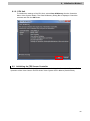


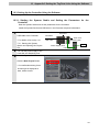
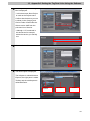
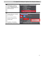

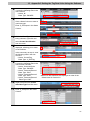


![13.56MHz [MIFARE] Contactless Smart Card](http://vs1.manualzilla.com/store/data/005689074_1-1b5ba2b7f854420e24ee51932ec4423a-150x150.png)