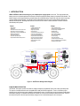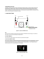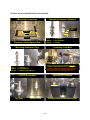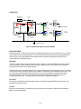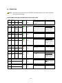
1
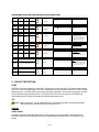
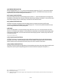
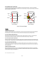
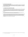
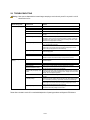
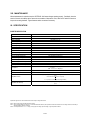
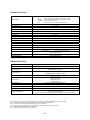
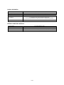
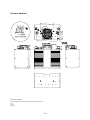
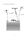
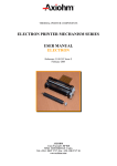
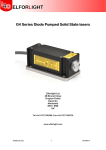
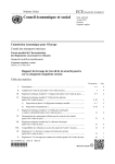
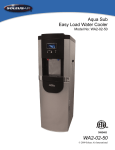
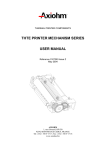
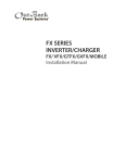
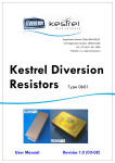
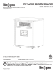
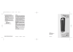
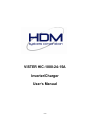
VISTER HIC-1000-24-15A Inverter/Charger User’s Manual 1 of 20 Table of Contents I II III IV V VI VII VIII IX X 2 4 5 6 9 10 13 14 15 15 20 Important Safety Instructions Introduction Main Functions Installation Operation Circuit Protection Power Output Operating Limits Troubleshooting Maintenance Specifications Warranty IMPORTANT SAFETY INSTRUCTIONS Warning: Before using the VISTER HIC-1000 inverter/charger, read and save these safety instructions. GENERAL SAFETY PRECAUTIONS VISTER HIC-1000 inverter/charger should only be used on the appropriate output voltage systems. Please refer to the specifications for more details. Improper use could cause the battery to explode, resulting in fire, personal injury, and damage to the inverter/charger. AC power supply to the charger should always include an equipment-grounding conductor. Never use a two blade to threeblade plug adapter or an extension cord with a male plug having only two blades. Always use an AC receptacle with a threeblade outlet and an extension cord with a three-blade male plug. Always unplug or turn off the AC power supply at the main distribution panel when working on the VISTER HIC-1000. Avoid working on or connecting power to the inverter/charger with wet hands or under wet conditions. Do not install the VISTER HIC-1000 in a zero-clearance compartment. Overheating may result. To avoid risk of fire and electrical shock, make sure that existing wiring is in good electrical condition, and that wire size is not undersized. Do not operate the VISTER HIC-1000 with damaged or substandard wiring. Even when the VISTER HIC-1000 has been completely disconnected, there can still be deadly voltages present at the output terminals. To remove these voltages, you must switch the unit on with the on/off switch. After one minute, the residual voltage will be discharged and any work can now be safely carried out. Under certain conditions your HDM product or a connected generator can start automatically. While working on an electrical installation, you must ensure that these appliances are disconnected before commencing any work. Also, the AC power source to the charger must be disconnected when working on the charger, to avoid sparks. 2 of 20 PRECAUTIONS WHEN WORKING WITH BATTERIES While working on batteries, there should always be a second person close to you or within your voice range, in case help is needed. Plenty of fresh water and soap must be at hand, so that in case of acid coming in contact with skin, eyes or clothes, the relevant areas can be thoroughly washed. If acid comes into contact with the eyes, you must thoroughly wash the eyes with cold running water for at least 15 minutes. It is recommended that you immediately consult a medical doctor. Baking powder neutralizes battery acid electrolyte. Always keep some near your batteries. Open flames, matches, smoking materials or other means of ignition should not be used in vicinity of battery or engine. Never charge frozen batteries. Do not drop a metal tool onto the battery. The resulting spark or short circuit on the battery or other electrical part may cause an explosion. The battery’s cover or a temporary cover of non-conductive material should be placed over the battery when working near it to prevent sparks. Remove personal metal items, such as jewelry and watches when working with a lead acid battery. A lead acid battery produces a short circuit current high enough to weld a ring or the like to metal, causing a severe burn. INSTALLATION PRECAUTIONS Warning: Operation of the VISTER HIC-1000 inverter/charger without a proper ground connection may result in an electrical safety hazard. Warning: To reduce the risk of electrical shock, make sure the remote switch is in the off position and disconnect both DC (battery) and AC (shorepower) power from the unit before performing electrical work on the system. Note: Always connect VISTER HIC-1000 to the battery first. This will allow the unit to initialize properly. LOAD DUMP WARNING Engine Running Battery Disconnect Switch Warning: When engine is running, DO NOT activate the battery disconnect switch. Disconnecting the batteries while the engine is running will cause a load dump surge from the alternator which will damage the inverter and/or the electrical system. 3 of 20 I. INTRODUCTION HDM's VISTER HIC-1000 inverter/charger is your complete power supply system on the road. This single product uses battery power to run onboard appliances and electronics, and then rapidly and cleanly charges your batteries when docked. The battery charger's pulse charging technology extends battery life and reduces battery charge time, while the inverter's high surge capacity handles demanding loads. An automatic transfer switch allows the power source to shift seamlessly between the batteries and shorepower. Watertight and economical, the VISTER HIC-1000 is a cleaner alternative to the APU and other diesel based power systems. Feature Inverter Charger High Density Waterproof Extruded Aluminum Case Construction Dimensions of a Group 31 Battery Appropriate for Wet and AGM Batteries Remote On/Off Switch LED Status Indicators Automatic Transfer Switch Replaceable External Waterproof Fan 1000W Isolated Inverter Modified Sine-Wave High Surge Capacity Power Limiting Input Reverse Polarity Protection Input Low Voltage Protection Input Overvoltage Protection Output Short Circuit Protection Output Overvoltage Protection High Temperature Protection Auto-Recovery Function Sleep Mode 15ADC Isolated Charger Patented Pulse Charging Algorithm AC Input Surge Protection Standby Mode Auto-Restart Mode Overvoltage Protection Short Circuit Protection Current Limiting Overload Protection Temperature Derated Charge DC Low Voltage With Timed Charging Auto Maintenance Mode AC Outlets A/C Controller Onboard Electronics and Power Equipment Air Conditioner HDM Battery Fuel Gauge Display VI STER ON Inverter /Charger AC OUT HDM Inverter/ Charger Control Panel Shorepower OFF HDM Battery Equalizer HDM Inverter/Charger HDM Battery Fuel Gauge Sensor Alternator Starter Bank HDM Battery Separator AC IN Shorepower Connection Auxiliary Bank Figure A – VISTER HIC-1000 Application Diagram INVERTER MODE DESCRIPTION VISTER HIC-1000 inverter provides 1000 watts of voltage and frequency-regulated AC power from a deep cycle battery bank. The output is a modified sine-wave and is compatible with virtually all consumer appliances. There is a low battery output shutdown circuit and high surge power available for starting electric motors. High efficiency ensures the longest possible battery life between recharges. The transfer switch allows the VISTER HIC-1000 to be connected to an external AC source. Some of the external AC power is used to operate the battery charger; the rest is switched through the unit to the output. 4 of 20 CHARGER MODE DESCRIPTION VISTER HIC-1000 battery charger incorporates a patented pulse charging technology to cleanly and rapidly charge lead acid and AGM deep cycle batteries. Battery charging is accomplished in 4 automatic stages: Bulk Charge, Absorptive Charge, Equalization Charge, and Float Charge. Alternating positive and negative pulses ensure that the plates accept the maximum charge to extend battery life and maximize battery capacity. The microprocessor-controlled VISTER HIC-1000 allows the unit to be left on, and minimal attention or maintenance is required. II. MAIN FUNCTIONS AC In AC Out Remote On/Off Switch Positive Terminal Negative Terminal Chassis Ground Screw UNIT MUST BE PROPERLY GROUNDED PER INSTALLATION INSTRUCTIONS TO AVOID DAMAGE TO THE UNIT. Fan Figure B – Top View of VISTER HIC-1000 FAN There is an exterior mounted fan to dissipate excess heat produced by VISTER HIC-1000 inverter/charger. Do not obstruct: allow at least 1 inch above the inverter/charger for adequate airflow. DC POWER TERMINALS There are two 3/8-16 power stud posts for DC connections, one positive and one negative. AC IN/OUT AND REMOTE CABLES AC IN, AC OUT, and Remote On/Off Switch cables originate from three openings on the top of the inverter/charger. AC IN cable has a three-blade male plug, while the AC OUT cable has a three-blade female receptacle. AC IN cable will allow the use of shorepower for operating electronic equipment and appliances and for charging the battery. AC OUT cable will connect to electronic devices to be run on either shorepower or on the batteries. VISTER ON Inverter/Charger Shorepower OFF Figure C – Remote On/Off Switch Panel 5 of 20 ON/OFF SWITCH On/off switch allows you to turn on or off the VISTER HIC-1000 inverter/charger. INVERTER/CHARGER INDICATOR (LED1) Inverter/charger LED Indicator displays GREEN when the inverter is on. Inverter/charger LED displays RED when the inverter is off, charger is on and shorepower is being used. SHOREPOWER (SP) INDICATOR (LED2) When the shorepower is connected, the Shorepower LED Indicator will be GREEN. When the inverter is on, the Shorepower LED Indicator displays no color. Please refer to the table in section IV for more detailed explanation of operating procedures and LED Indicators. III. INSTALLATION Warning: Operation of the VISTER HIC-1000 inverter/charger without a proper ground connection may result in an electrical safety hazard. Warning: To reduce the risk of electrical shock, make sure the remote switch is in the off position and disconnect both DC (battery) and AC (shorepower) power from the unit before performing electrical work on the system. Note: Always connect VISTER HIC-1000 to the battery first. This will allow the unit to initialize properly. INSTALLATION LOCATION VISTER HIC-1000 inverter/charger should be installed in a location that meets the following requirements: Dry - VISTER HIC-1000 is waterproof. Whenever possible, it is best to install the inverter/charger in a dry location. Cool - Ambient air temperature should be between 0°C (32°F) and +50°C (122°F), the cooler the better. Ventilated - Allow at least one inch of clearance around the inverter/charger for adequate airflow. Distance from batteries - Avoid excessive cable lengths. Use the recommended wire lengths and sizes. 6 of 20 VISTER HIC-1000-24-15A INVERTER INSTALLATION PROCEDURE Mounting Preparation Mounting Fasteners (Bottom) 93.8 .7") m(6.5 ") (3 mm 160mm(6.3") 165m 6.4mm(0.25") minimum Ø3/8" 320mm(12.6") Top: ¼” Flat Washer Middle: ¼” Spring Washer Bottom: ¼” Hex Nut Placement Inside Battery Box Mounting Fasteners (Top) Fastening Thru-Bolt 30 0 Fasten ¼” Hex Nut with 7/16" Socket at 30 in-lb or until Spring and Domed Washer become flatten out. Top: ¼” Hex Nut Middle: ¼” Spring Washer Bottom: ¼” Rubber Domed Washer WARNING! DO NOT OVER TIGHTEN THE THRU-BOLTS OR INSTALL HARDWARE IN THE WRONG ORDER! WATER LEAKAGE MAY RESULT AND DAMAGE THE UNIT. Correct Installation Top Side Installation Complete Bottom Side Unit Mounted Inside Battery Box 7 of 20 CONNECTIONS Remote On/Off Switch Panel In-Line Fuse On INV/CHG SP I 0 Shorepower Off +DC Line AC In Neu DC Fuse Gnd Earth Ground HIC-1000 Battery AC input and output ground are connected to case internally . Inverter/Charger -DC AC Out Connection A (-DC to GND) GFCI Line Line Neu Neu Gnd Gnd AC Output Chassis Ground Lug Connection Chassis Ground Figure D – System Grounding And Connection Diagram SYSTEM GROUNDING Grounding connection “A” (Figure D) can be floating or connected to chassis ground. AC input must be from a 20AAC protected source (shorepower) with a grounding conductor. Use of GFCI (Ground Fault Circuit Interrupter) must be employed at the AC output connection. Not complying with the recommended grounding configurations will damage the VISTER HIC-1000 inverter/charger and/or void product warranty. BATTERIES To prepare the battery cables, press on the cable tabs or shoes, if necessary. Connect the RED cable to the battery’s positive fuse or circuit breaker. Connect the BLACK cable to the battery’s negative terminal. Take precaution when connecting the second cable to the battery, in case a spark is produced. Cables should be as short as possible, ideally, less than 10 feet, and large enough to handle the required current, in accordance with the electrical codes or regulations applicable to your installation. Cables that are not an adequate gauge (too narrow) or are too long will cause decreased inverter/charger performance such as poor surge capability and frequent low input voltage warnings and shutdowns. These low input voltage warnings are due to DC voltage drops across the cables from the inverter/charger to the batteries. The longer and more narrow the cables, the greater the voltage drop. AC OUTPUT AC Output has a three-blade receptacle and requires the use of a 12 AWG wire between VISTER HIC-1000 and the control panel aboard your vehicle or vessel. AC INPUT AC Input has a three-blade plug. Connect this plug to your shorepower source for battery charge function with Shorepower Bypass to the AC Out Receptacle. 8 of 20 IV. OPERATION Warning: On/off switch turns the control circuit in the VISTER HIC-1000 inverter/charger on or off. It does not disconnect power from the inverter/charger. INVERTER MODE OPERATING CONDITIONS AND LED STATUS INDICATORS On/Off Switch SHORE POWER INVERTER CHARGER INV /CHR ON OFF ON OFF SP On/Off Switch SHORE POWER INVERTER CHARGER INV /CHR OFF Sleep Mode ON OFF SP Solid Green “Blank” Blinking Green (0.5sec ON; 4.5sec OFF) “Blank” (Input Low Voltage) On/Off Switch SHORE POWER INVERTER CHARGER INV /CHR Input Low Voltage Warning OFF SP CHARGER INV /CHR ON OFF On/Off Switch SHORE POWER INVERTER ON OFF Input OVP OFF SP Intermittent Blinking Green 3x (0.2s ON/OFF); 4.5s OFF Condition Note Ext charger present (Vin>26(±0.5)VDC or voltage increase within 10 sec interval) or No overvoltage, no low voltage, no overloading, no over temperature Inverter normal Condition Note Ext charger not present (Vin<26(±0.5)VDC or no voltage increase detected within 10 sec interval) and AC load current <0.3(±0.2)AAC for >6(±0.5) hour or Vin<21(±0.5)VDC for 2 sec (input low voltage condition) Input Low Voltage Auto-Recovery Inverter will auto-restart if Vin>26(±0.5)VDC or voltage increase within 10 sec interval Condition Note Vin<18(±0.5)VDC (See Input Low Voltage Auto -Recovery) Manual cycling of switch OFF-ON will restart inverter when input voltage is within operating limits LED1 will return to solid GREEN “Blank” Blinking Green (0.5sec ON; 0.5sec OFF) Condition Note Vin>31(±0.5)VDC Input Overvoltage Auto-Recovery After 5 sec, if input <31(±0.5)VDC, inverter will auto-restart “Blank” Manual cycling of switch OFF-ON will restart inverter when input voltage is within operating limits LED1 will return to solid GREEN On/Off Switch SHORE POWER ON OFF On/Off Switch SHORE POWER INVERTER CHARGER INV /CHR Overload; SCP; OVP OFF SP “Blank” INVERTER CHARGER INV /CHR “Blank” OFF SP “Blank” BATTERY INV /CHR “Blank” DISCONNECT SP “Blank” On/Off Switch INV /CHR “Blank” OFF SP “Blank” ON On/Off Switch ON OFF Over Temp Solid Orange Condition Note Output overload or output short circuit or output overvoltage Requires manual restart of HIC-1000 Condition Note TINV-Thermistor1 > +75(±5)oC typ Inverter will turn OFF; fan will be ON Over Temperature Auto-Recovery Inverter will auto-restart with 45oC hysteresis Manual cycling of switch OFF-ON will restart inverter when temperature is within operating limits LED1 will return to solid GREEN Condition Note HIC-1000 is disconnected from battery INV Mode: no AC out Turn switch OFF before reconnecting HIC1000 to the battery. Turn switch ON to restart the inverter. 9 of 20 Condition Note Switch is in OFF position HIC-1000 will be in OFF-state CHARGER MODE OPERATING CONDITIONS AND LED STATUS INDICATORS On/Off Switch SHORE POWER INVERTER CHARGER INV /CHR ON ON OFF ON SP On/Off Switch SHORE POWER INVERTER CHARGER INV /CHR SP ON ON OFF Thermally Derated Charge On/Off Switch SHORE POWER INVERTER CHARGER INV /CHR ON ON OFF Overload; SCP SP On/Off Switch SHORE POWER INVERTER CHARGER INV /CHR ON ON OFF Low Voltage Timed Charge On/Off Switch SHORE POWER INVERTER CHARGER ON ON OFF Low Voltage Auto-Stop SP INV /CHR SP Solid Red Condition Note No overloading, no overvoltage, no over temperature Charger Normal with Shore Power Bypass Condition Note TCHG-Thermistor > +75(±15%)oC typ Thermally derated charge Solid Green Solid Red Shore Power Bypass is ON Solid Green Solid Red Condition Note Output overload or output short circuit Charger goes into Hiccup Mode Solid Green Blinking Red/Orange (4sec RED; 1sec ORANGE) Charger will auto-recovers or manual cycling of swith OFF-ON will restart charger when conditions are within operating limits Condition Note Charge battery with voltage >10VDC and <20(±0.5)VDC for 0.5(±0.1)hr Low Voltage Timed Charging Charger ON Solid Green Blinking Red/Orange (0.5sec RED; 0.5sec ORANGE) Shore Power Bypass is ON Shore Power Bypass is ON Condition Note <18(±0.5)VDC after 0.5(±0.1)hr Low Voltage Auto-Stop Charger stopped Solid Green Shore Power Bypass is ON Requires manual restart of HIC-1000 On/Off Switch BATTERY ON DISCONNECT INV /CHR “Blank” SP “Blank” On/Off Switch INV /CHR “Blank” OFF SP “Blank” Condition Note HIC-1000 is disconnected from battery CHG Mode: charger OFF and no SP Bypass Turn switch OFF before reconnecting HIC1000 to the battery. Turn switch ON to restart the charger and activate SP Bypass. Condition Note Switch is in OFF position HIC-1000 will be in OFF-state V. CIRCUIT PROTECTION FUSING VISTER HIC-1000 inverter/charger has no internal fuse. External fuses for on/off circuit and DC input must always be employed. An ATO or ATC 3ADC with voltage rating of 32VDC fuse or equivalent must be used at the remote on/off circuit. A 70ADC fuse with voltage rating 32VDC or equivalent must be used to meet product safety requirements. AC Input must be from a 20AAC protected source (shorepower) with a grounding conductor. This will limit the AC current draw in the event of the VISTER HIC-1000 internal charger and the SP Bypass are exceeding the maximum rated operating current. GFCI Warning: Risk of electric shock. Use only Hubbell GFBF20GYL or equivalent ground-fault circuit-interrupter receptacle. Other types may fail to operate properly when connected to this unit. INVERTER POWER LIMITING VISTER HIC-1000 inverter has a power limiting circuit to protect unit during over current conditions. When output current exceeds the maximum power limit threshold, unit will go into shutdown mode and manual restart of the VISTER HIC-1000 is required. 10 of 20 HIGH TEMPERATURE PROTECTION When the internal thermistor (TINV-Thermistor1) senses the internal temperature higher than +75(±5)°C, inverter will auto-shutdown to prevent VISTER HIC-1000 from overheating while the external fan remains on. VISTER HIC-1000 will auto-recover when temperature drops with the assisted cooling of the external fan (Note 1). INPUT LOW VOLTAGE PROTECTION In the event of battery drain when no external charging current is present (Note 2), inverter will automatically turn off and goes into Sleep Mode to prevent batteries from being over drained and cause permanent damage to the batteries. Inverter will auto-restart when external charging is present or manual cycling of the switch off-on will restart the inverter. INPUT OVERVOLTAGE PROTECTION VISTER HIC-1000 inverter is equipped with input overvoltage protection to shutdown the unit when high DC voltage >31(±0.5)VDC is detected from the batteries or any external charging source. The auto-recovery feature will restart the inverter once the voltage reaches within the safe operating levels. SLEEP MODE Function of the Sleep Mode is to conserve the battery energy when inverter is not in use. The internal self-timer will activate when low or no AC output current is detected. Once the preset time is reached with no AC load and/or external charger present, inverter will go into Sleep Mode. Inverter will auto-restart when external charging is present or manual cycling of the switch offon will restart the inverter. (See also Input Low Voltage Protection) OUTPUT SHORT CIRCUIT PROTECTION VISTER HIC-1000 inverter is protected from output circuit conditions from any defective electronic and electrical equipment connected to the AC output. Unit will immediately shutdown with solid ORANGE warning signal shown at the LED1 indicator. Defective equipment must be disconnected and manual cycling of the switch is required to restart inverter. OUTPUT OVERVOLTAGE PROTECTION VISTER HIC-1000 has an output overvoltage detection circuit that shutdowns the inverter when output voltage exceeds the rated voltage limits to prevent high AC voltages being applied to the electronic and electrical equipment in the system (Note 3). Note 1: 45°C hysteresis of TINV-Thermistor1 for auto-recovery of the inverter. Note 2: External charger and/or alternator. Note 3: To determine if AC output exceeds rated limits and triggers output overvoltage protection, restart the inverter without any AC load and measure the AC output voltage. If so, contact factory for service. 11 of 20 INPUT REVERSE POLARITY PROTECTION An external DC fuse must be used to protect the VISTER HIC-1000 and the electrical system. Follow the recommended connection sequence for safe installation of the VISTER HIC-1000 inverter/charger. Always connect the battery to DC fuse first before connecting to VISTER HIC-1000. Connection Step 1 Connection Step 1 Battery Connection Step 3 DC Fuse Battery Blown DC Fuse Connection Step 2 or 3 Connection Step 2 Connection Step 3 or 2 HIC-1000 HIC-1000 Correct Installation Incorrect Installation Figure E – DC Connection Diagram CHARGER AC INPUT SURGE PROTECTION VISTER HIC-1000 has a built-in AC input surge protection circuit that protects both the internal charger and the AC Bypass to the electrical system. AC Input must be from a 20AAC protected source (shorepower) with a grounding conductor. DC OUTPUT OVERVOLTAGE PROTECTION While batteries are being charge by the internal charger, if battery voltage overshoots >30.2(±0.5)VDC, charger will stop to prevent batteries from being over charged. Charger will auto-restart when batteries voltage is <28(±0.5)VDC. DC OUTPUT SHORT CIRCUIT PROTECTION Charger is protected by the external DC fuse and short circuit protection circuit when exposed to short circuit conditions at the DC output terminals. Charger will go into hiccup mode (pulsating current) and auto-recovers when the short circuit is removed. DC OUTPUT OVERLOAD PROTECTION Overload protection circuit protects charger from overloading conditions where the system is drawing more current than the maximum rated charging current. Charger will go into hiccup mode (pulsating current) and auto-recovers when conditions are within operating limits. TEMPERATURE DERATED CHARGE When the internal charger thermistor (TCHG-Thermistor) senses internal temperature higher than +75(±15%)°C, the charger will derate the charging current to prevent charger from overheating. Charger will resume rated power when temperature reduces with the continuous cooling of the external fan (Note 4). Note 4: See charger specification for fan operation. 12 of 20 DC LOW VOLTAGE WITH TIMED CHARGING DC low voltage with timed charging feature is used in attempt to recharge a drained battery or battery bank. Charger will attempt to charge the battery between the voltage of 10(±0.5)VDC to 20(±0.5)VDC for 0.5(±0.1)hr. If battery voltage remains <18(±0.5)VDC after the preset charging time, charger will stop to prevent battery from overheating due to shorted plates (Note 5). Manual cycling of switch is required to restart charger. VI. POWER OUTPUT OPERATING LIMITS VISTER HIC-1000 inverter/charger will operate most AC loads within its power rating. When determining whether a microwave oven can be operated by the inverter, remember that the power commonly advertised for microwave ovens is the cooking power (the power delivered to the food), not the power actually consumed by the microwave. The microwave will consume 40% to 100% more than its advertised cooking power. Check the rating sticker on the back of the microwave to determine its actual power draw. If you are operating several loads from the inverter, turn them on separately after the inverter has been turned on. This will ensure that the inverter does not have to deliver the starting currents for all the loads at once. The inverter may not be able to start some motors even though their rated current draw is within the range of the inverter. If the motor refuses to start, observe the battery voltage indicator while trying to start the motor. If the battery voltage indicator drops below 21VDC while the inverter is attempting to start the motor, this may be why the motor will not start. Make sure that the battery connections are good and the battery is fully charged. If the connections are good and the battery is charged, but the voltage still drops below 21VDC, you may need to use a larger battery. Note 5: Continuous charging of the low voltage batteries is not recommended. Battery with low DC voltage has symptom of shorted plate(s). Continuous charging will cause battery to overheat. Contact factory for battery replacement. 13 of 20 VII. TROUBLESHOOTING Warning: Never open or disassemble the inverter/charger, attempting to service the unit yourself. It may result in a risk of electrical shock or fire. Problem and Symptoms Possible Cause Solution Inverter is not operating. Remote on/off switch is off. Bad remote connection or wiring. Close remote on/off switch and wait 15 seconds for inverter to power up. Check remote connection and wiring for loose connection or damage. Blown in-line fuse. Blown DC fuse. Check in-line fuse at the Remote connection. Replace fuse if necessary. Check DC fuse. Verify total loading is less than 1000W. Bad AC OUT connection or wiring. Check AC OUT connection, wiring, and AC OUT receptacle for loose connection or damage. Unit overheating or overloading. If external fan is on and INV (LED1) is “Blank”, inverter has shutdown due to over temperature. This may occur due to excessive continuous loading or inadequate operating space. Check your AC loading. Verify total loading is less than 1000W. Relocate unit to a larger space if necessary. Verify battery voltage. Unit will auto-shutdown when battery voltage is less than 21VDC. Charge battery if necessary. Low battery voltage. High battery voltage. Charger or AC Bypass is not operating. Check DC cables. Make sure DC cables meet length and size requirement. Long cable lengths or small cable size will have significant voltage drop across DC cables. Change to appropriate DC cables if necessary. Verify battery voltage. Unit will auto-shutdown when battery voltage is over 31VDC. Check charging system. Unit in Sleep Mode. Short circuit condition. Low or no load for over 6 hours. Cycle remote on/off switch to restart inverter. Unit will auto-shutdown when detect short circuit at the AC output. Remove defective equipment and restart inverter by cycling remote on/off switch. Remote on/off switch is off. Close remote on/off switch and wait 7 seconds for charger to power up and activate SP Bypass. Bad remote connection or wiring. Check remote connection and wiring for loose connection or damage. Blown in-line fuse. Check in-line fuse at the Remote connection. Replace fuse if necessary. Bad AC IN connection or wiring. Unit may go into inverter mode when powered up. Check AC IN connection, wiring, AC SP (shorepower) connection, and circuit breaker. Tripped AC SP (shorepower) circuit breaker. Unit may go into inverter mode when powered up. Verify total current consumption is less than 20AAC from the SP (shorepower) source. Charger may draw up to 6AAC leaving 14AAC for AC Bypass application. Bad AC OUT connection or wiring. Check AC OUT connection, wiring, and AC OUT receptacle for loose connection or damage. Low battery voltage. Charger will auto-stop if battery voltage is less than 18VDC after charging for half an hour. Check battery if necessary. Cycle remote on/off switch to restart charger. Check DC cables. Make sure DC cables meet length and size requirement. Long cable lengths or small cable size will have significant voltage drop across DC cables. Change to appropriate DC cables if necessary. High battery voltage. Charger will be in Standby mode when battery voltage is over 28VDC. Charger will auto-restart when battery voltage is less than 28VDC. Please refer to the table in section IV for more detailed explanation of operating procedures and diagnostic LED Indicators. 14 of 20 VIII. MAINTENANCE Minimal maintenance is required to keep the VISTER HIC-1000 inverter/charger operating properly. Periodically, clean the exterior of the unit with a damp cloth to remove the accumulation of dust and dirt. Also, check the DC and AC connections. Inspect the mounting hardware. Tighten fasteners and/or connections if necessary. IX. SPECIFICATION INVERTER SPECIFICATION Output Waveform Output Power Output Power Limit Output Surge Rating Maximum Output Surge Current Output Voltage Output Voltage Regulation Output Overvoltage Shutdown Output Frequency Output Short Circuit Protection Input Voltage Range Input Low Voltage Shutdown Input Low Voltage Auto-Recovery Input Low Voltage Warning Input Overvoltage Shutdown Input Overvoltage Auto-Recovery High Temperature Shutdown High Temperature Auto-Recovery Modified Sine-Wave 1000W Continuous 1300(±200)W 2400(±200)W for 1 sec 20AAC 120VAC 100 ~ 130VAC 110 ~ 140% VOUT 60(±4)Hz Auto Shutdown (Note 6) 22VDC ~ 30VDC (±0.5VDC) < 21(±0.5)VDC for 2 sec (see Sleep Mode Auto-Recovery) < 18(±0.5)VDC (Note 7) > 31(±0.5)VDC < 31(±0.5)VDC for 5 sec TINV-Thermistor1 ≥ +75(±5)°C 45°C Hysteresis ON - TINV-Thermistor2 > +45(±5)°C (Note 8) OFF - TINV-Thermistor2 < +30(±15)°C Fan Operation Input Reverse Polarity Protection Efficiency External Fuse > 91% External charger not present (VIN < 26(±0.5)VDC and no voltage increase within 10 sec interval) and Sleep Mode Function AC load current < 0.3(±0.2)AAC for > 6(±0.5)hr or VIN < 21(±0.5)VDC for 2 sec (Input Low Voltage Condition) Sleep Mode Auto-Recovery External charger present (Vin > 26(±0.5)VDC or voltage increase within 10 sec interval) (Note 6) Specifications typical at 25°C unless otherwise stated and are subject to change without notice. Note 6: Manual cycling of switch OFF-ON will restart the inverter. Note 7: Input Low Voltage Warning (see section IV – Inverter Mode LED Status Indicators) alerts operator that inverter has shutdown due to low voltage condition, but the battery is still being drained by other DC components. Note 8: Fan will operate when TINV-Thermistor2 > +45(±5)°C during Input Low Voltage, Input Overvoltage, or High Temperature conditions. 15 of 20 CHARGER SPECIFICATION 4-Stage Pulse Charging Algorithm with Temperature Derated Charge for AGM batteries Charging Method AC Input Voltage AC Input Frequency Minimum Battery Voltage Maximum Charger Input Current Maximum Charge Rate Efficiency Charge Voltage Low Voltage Timed Charging Low Voltage Auto-Stop Standby Mode Auto-Restart Mode Overvoltage Protection DC Output Short Circuit Protection Overload Auto Shutdown Temperature Derated Charge Fan Operation Current Limiting Range Auto Maintenance Mode Bulk: Absorption: Equalization: Float: Maximum charging current to battery. Duration depends on Ahr rating. Constant absorption voltage to battery. Duration depends on Ahr rating. Vmax is 29.6VDC. Duration is 1 hour. Constant float voltage of 27VDC with load current on demand. 100 ~ 130VAC 54 ~ 66Hz 10VDC 6AAC 15(±2)ADC > 85% 10 ~ 29.6VDC Charge battery with voltage <20(±0.5)VDC for 0.5(±0.1)hr <18(±0.5)VDC after 0.5(±0.1)hr (Note 9) > 28(±0.5)VDC < 28(±0.5)VDC > 30.2(±0.5)VDC External Fuse; Hiccup with Auto-Recovery Hiccup with Auto-Recovery TCHG-Thermistor ≥ +75(±15%)°C ON – Charging; TCHG-Thermistor ≥ +43(±15%)°C during Float Mode OFF – Charge Complete 15(±2)ADC Float Charge @ 27(±0.5)VDC GENERAL SPECIFICATION Maximum AC Input/Bypass Current Automatic Transfer Switch 20AAC (Note 10) 20AAC maximum Turn ON Time (Note 11) INV Mode: 14(±5) sec CHG Mode/SP Bypass: 5(±4) sec Transfer Time (Note 12) INV Mode to CHG Mode/SP Bypass: 5(±4) sec CHG Mode/SP Bypass to INV Mode: 14(±5) sec AC Input Surge Protection Isolation Voltage System Grounding Operating Temperature Range Storage Temperature Range Cooling Method External Fuse and Breaker 4(±10%)kV (Note 13) 1260VAC (ACIN~Case) 1260VAC (ACIN~DCOUT) 500VAC (DCOUT~Case) 1260VAC (DCIN~ACOUT) (see Figure D - System Grounding Configuration) -40 ~ +70°C (-40 ~ +158°F) -40 ~ +95°C (-40 ~ +203°F) External Waterproof Fan (Note 14) On/Off Switch: ATO/ATC 3ADC 32VDC Fuse (required) DC Input: 70ADC Fuse (required) AC Input: “Must be from a 20AAC protected source (shorepower) with a grounding conductor” Note 9: If battery remains <18(±0.5)VDC after being charged for 0.5(±0.1)hr, charger will stop. Manual cycling of switch off-on will restart the charger. Note 10: AC Input/Bypass current is shared among the VISTER HIC-1000 internal charger and bypass applications. Note 11: Initial time to power up VISTER HIC-1000 after switching remote switch to on position. Note 12: Transfer time is the duration between mode transfer beginning when shorepower is applied or removed from the AC IN. Note 13: VISTER HIC-1000 meets IEC 61000-4-5 Level 4 requirement. Note 14: Replaceable external waterproof fan (P/N: KIT-FAN0001). 16 of 20 PHYSICAL INFORMATION Enclosure Description Dimensions (LxWxH”) Net Weight Mounting Orientation Fully Enclosed Aluminum Case 12.6 x 6.5 x 10” (320 x 165 x 258 mm) 25 lbs (11.3 kg) Vertical with Power Posts on top ¼” through-bolts from top or bottom with 30 in-lb fastening torque Mounting Method Recommend using rubber washers, flat or fender washers, and lock or spring washers during installation Ventilation Allow at least 1 inch above unit for adequate airflow EXTERNAL CONNECTORS / INTERFACE AC Input Connection AC Output Connection DC Connection Remote Control Connection 20A 12AWG/3 Waterproof Cable 20A 12AWG/3 Waterproof Cable 3/8-16 UNC-2A Thread Brass Positive and Negative Power Posts with 120(±15%) in-lb fastening torque 18AWG/6 Waterproof Connector 17 of 20 MECHANICAL DIMENSIONS Neg 78 Pos 42 253 15.2 213 14 165 321 MECHANICAL TOLERANCES: Dimensions in millimeters unless otherwise specified and subject change without notice. X (±2) X.X (±1) Angle (±1°) 18 of 20 94 3.1 3.1 160 EXTERNAL CONNECTORS / INTERFACE CABLE INFORMATION Remote Cable: 260(±25) Replaceable External Waterproof Fan (P/N: KIT-FAN0001) 19 of 20 X. WARRANTY Please do not remove the identification plate, which displays the model serial number. The warranty period for your HDM product is 1 year after purchase date. HDM warrants this product against defects in material or workmanship to the original purchaser. No warranty will be provided on units that have not been paid for in full. This warranty does not extend to products which have been opened, altered or repaired by persons other than those authorized by HDM, or to products which become defective due to acts of God, fire, sabotage, vandalism, contaminated fluids, negligence or failure to operate, house and maintain the product in accordance with the instructions provided in this manual. It is extremely important that the user strictly adhere to all installation instructions contained within this manual. Failure to do so will void your warranty. Except for the foregoing expressed warranty, HDM makes no warranty, expressed or implied, including but not limited to, the warranty of merchantability or fitness for a particular purpose. HDM will repair or replace the defective product in accordance with its best judgment. For service under warranty, the buyer or installer must first contact HDM to obtain a Return Materials Authorization (RMA) number and shipping instructions before returning the product to the factory, at his or her expense. The user will need to provide proof of purchase for the HDM product. HDM will pay return freight charges, if the product is found to be defective, within the terms of the warranty. Repair or replacement of any unit does not extend the original warranty terms in any way. This warranty does not cover repairs made necessary due to the product coming in contact with dirt, abrasives, moisture, rust, corrosion, varnish or other similar substance, or failure due to poor-quality or poorly conditioned batteries. HDM reserves the right with some models to supply an accredited installer with replacement part. The may allow the unit to become operable much quicker. In this case, HDM is not responsible for any costs of the installer’s time or related expenses incurred. Replacement parts are sent at HDM’s discretion. HDM will in no way be held responsible for any loses incurred due to the malfunctioning or failure of a product. Suitably qualified personnel must carry out wiring. Failure to do so will void warranty. If you have any questions about this warranty, please contact HDM Systems Corporation at 500 Lincoln Street Allston, MA 02134 Ph: 617.562.4054 Fax: 617.562.4013 Email: [email protected] Web: www.HDM-Sys.com URM-VISTER HIC-1000-24-15A R1 20090706 20 of 20