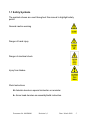
1
Kestrel e400i250Vdc
Type 0404-3000-250 for Gridtie Applications
With Conditional Two Year Warranty
Installation and Maintenance Manual
To report errors, omissions or improvements please write to:
[email protected] or [email protected]
Owners Notes (Record the serial numbers before installation!)
Turbine Serial Number
__________________
Blade 1 S/N
Blade 2 S/N
Blade 3 S/N
______________ _____________ _____________
General Notes:
Document No. 0404M006
Revision 1,0
Date: March 2009
2
Index
1.0 Safety Warnings and Notes
4
1.1 Safety Symbols
5
2.0 The Tower
6
2.1 Mounting Flange and Tower Top
7
3.0 Unpacking the Wind Turbine
8
4.0 Turbine assembly and Installation
10
4.1 Identification Marking
4.2 Tail Assembly
4.3 Tail Boom Weld assembly to the Generator
4.4 Generator to the Tower
4.5 Tail Assembly to the Boom
4.6 Blades and Nosecone Stiffener Ring
4.7 Balancing the Blades
4.8 Nacelle and Nosecone
5.0 Electrical Installation
19
6.0 Installation Commissioning
22
7.0 Maintenance Schedule
23
7.1 Wind Power Class
7.2 Planned Maintenance schedule
8.0 Questions and Answers
25
9.0 Technical Specification
26
10.0 Compliance
27
11.0 Warranty
28
12.0 Annexures
Annexure 1
Annexure 2
Annexure 3
Annexure 4
Annexure 5
Annexure 6
General Information
Choosing a Site
Kestrel Patented Voltage Limiter
Gridtie Inverters
Installation Check List
Warranty Registration
Document No. 0404M006
Revision 1,0
29
32
34
35
36
37
Date: March 2009
3
Disclaimer
Kestrel Wind Turbines makes every effort to give accurate information in this
manual and is in no way liable for any error or omission. The user of this
manual assumes full responsibility and risk
We appeal to your common sense to read and apply the safety notes. Consult a
professional engineer and take advice if you are unsure.
1 Safety and Warning Notes
Accidents can easily occur and there are always inherent dangers
associated with any type of machine. Tower installations pose their own
dangers. Always work carefully and have an assistant wherever possible.
All installation work should be completed at ground level wherever
possible. Be very aware of the blades during installation. Consult a civil
engineer or reputable builder if you are unsure.
Maintain a healthy respect for this wind turbine. Use good handling
methods and take precautions to avoid physical injury. The Kestrel e400i
output voltage can become dangerous and even lethal when running on
open circuit. Always short the output wires together when the turbine is
disconnected. Do not work on the system when the turbine is running or
when lightning is possible.
Disconnecting any wire may result in a spark. The presence of explosive
hydrogen from battery charging is always a possibility. Adequate
ventilation must be provided for battery installations. Wire sizes must be
correct for the powers supplied. Fire can result from shorts created on a
battery. Respect the system and use common sense. Consult a qualified
electrician if you are unsure.
Slack bolts, poor workmanship and loose electrical connections must be
avoided. The turbine blades are dangerous. Respect a rotating turbine.
Always shut the turbine down before approaching by operating the brake
switch on the controller or shorting the generator output. Preventative
maintenance is always the best. Checks are best carried out in calm
weather conditions. Avoid any maintenance or inspection during windy
weather.
Document No. 0404M006
Revision 1,0
Date: March 2009
4
1.1 Safety Symbols
The symbols shown are used throughout this manual to highlight safety
points
General caution warning
Danger of hand injury
Danger of electrical shock
Injury from blades
Work Instructions
Asterisk denotes a special instruction or reminder.
► Arrow head denotes an assembly/build instruction.
Document No. 0404M006
Revision 1,0
Date: March 2009
5
2.0 The Tower
Three possible tower types are shown above. The most affordable
erection is a guyed tower that is raised and lowered with a jin pole
The guyed tower can be constructed to great heights using a lattice
frame as the pole section. It requires the largest footprint and more
maintenance checks.
The tripod tower is also raised and lowered with a jin pole. Being free
standing, it is of a much heavier and rigid construction. Cost restricts
the practical height but a small footprint often makes it a popular
choice.
A scissor tower is the usually the most expensive erection and is cost
restricted in height. It gives the safest and most convenient
installation. The turbine can be simply raised and lowered for
inspection and maintenance with all work being done at ground level.
Once again the footprint is small and the ground area required to
lower the tower is less than other towers.
Other tower types include lattice construction and monopole taper
towers. Kestrel supplies standard approved towers and can provide
the turbine characteristics and parameters for tower design.
The e400i has a tower top mass of approximately 220kg (485lbs) and
is not considered suitable for roof mounting or fitting to outrigger
systems on existing masts or towers.
Document No. 0404M006
Revision 1,0
Date: March 2009
6
2.1 Mounting Flange and Tower Top
The Kestrel e400i is mounted on the tower with a
circular flange. A suitable matching tower flange
is supplied with the turbine.
The following specification is recommended for
the top pipe section of the tower. Mild steel pipe grade 350WA
OD139,7mm (5,5”). Length of 2m (77”) and minimum wall thickness
of 4,5mm (0,177”).
A standard adapter pipe is available from Kestrel where
the turbine will be fitted to an alternative structure. The
pole includes a securing point for the tower cable. Consult
your dealer for more details.
Document No. 0404M006
Revision 1,0
Date: March 2009
7
3.0 Unpacking the Wind Turbine
A Packing list is packed with the product. Ensure that all parts are
present. Notify your dealer of any shortages.
The e400i is contained in one shipping crate. Check the crate for any
transit damage and then carefully remove the top of the crate to
reveal the contents. Check that everything is intact. Pay special
attention to the blade package. Carefully remove all the parts for safe
storage. The last item to be removed is the generator assembly,
which is fully secured to the packing case base.
The generator and pitch control is factory assembled. The complete
assembly weighs approximately 150kg.
Document No. 0404M006
Revision 1,0
Date: March 2009
8
Unpack and check the following parts. Inform your supplier of any
defects or shortages.
► Remove the blade package and store safely.
► Remove the nacelle and nosecone with ring and store safely.
► Remove the two boom sections.
► Remove the two tail plates.
► Remove any other accessories that were shipped for you.
► Locate and remove the fastener pack (assembly grease inc.).
► Remove the complete generator assembly.
Note: The fasteners are supplied in marked bags. Each bag contains
a set of fasteners for different parts of the turbine. The enclosed
grease is used on all nuts from M10 upwards.
Note: One additional fastener pack contains one spare unit of every
fastener used on the turbine.
Lifting Eye Here
It may be useful to remove the sides of the
packing case to access the assembly.
Remove the securing bolts and pads to
free the generator assembly. If possible,
use lifting gear to remove the assembly
from the case. Otherwise have at least
three other assistants to lift the assembly
from the case. Two lifting straps may be
fitted to the generator for lifting. Beware of
the generator tipping forward and
causing injury to hands.
Beware not to damage the output cables below the generator.
The generator assembly is heavy at the front and will easily tip
over. When installed, the turbine is balanced on the yaw shaft.
Document No. 0404M006
Revision 1,0
Date: March 2009
9
4.0 Turbine Assembly and Installation
You will need the following hand tools.
► Trestle, table or other support to support the turbine that is safe for
250kg (550lbs).
► Plastic or rubber mallet.
► Full set of ring spanners from 10mm – 22mm.
► Metric socket wrench set.
► set of standard screwdrivers (plain and Philips).
► Torque wrench suitable for torques of 0 – 180Nm (132lb ft).
► electrical pliers and cutters.
Refer to the diagrams and follow the instructions to assemble the
complete wind turbine.
This manual assumes that the support tower is already installed and
lowered to ground level ready for turbine installation.
4.1 Identification Marking
The turbine is fitted with a
rating label similar to the
image.
Note down your turbine serial
number for future reference!
Document No. 0404M006
Revision 1,0
Date: March 2009
10
4.2 Tail Assembly
Observe hole position
on top of boom
ASSEMBLE EXACTLY AS SHOWN IN THE DIAGRAM. FIT ALL THE
FASTENERS BEFORE TIGHTENING.
The tails will be in the middle line of the boom
You need the fastener bag marked “Tail Assembly” for this work.
► Top (2) and bottom (3) tail plate to boom (1) with four off stainless
bolt sets (6). Nuts and washers on the bottom.
► Two rear stiffeners (4) to boom (1) with one stainless bolt set (6).
► Two front stiffeners (4) to boom (1) with one stainless bolt set (6).
► Bolt all stiffeners (4) and (5) to top and bottom tail plates (2) and
(3) with four off bolt set (7).
► All tail fasteners are M6. Torque all fitted bolts to 10Nm (7.5ft lb).
Document No. 0404M006
Revision 1,0
Date: March 2009
11
4.3 Tail Boom Weld Assembly to the Generator
THE GENERATOR SHOULD BE FITTED ON THE TOWER
BEFORE FITTING THE TAIL ASSEMBLY
TO THE GENERATOR.
FIT ALL THE FASTENERS BEFORE TIGHTENING.
ASSEMBLE EXACTLY AS SHOWN IN THE DIAGRAM.
You need the fastener bag marked “Tail Boom weld Assembly” for
this work.
► Fit the boom (8) to the tail boom flange (9) with two bolt sets (10)
(put a little grease on the nut thread). Torque to 50Nm (36ft lb).
► Fit the assembled flange and boom to the generator with all eight
allen cap screws and spring washers (11).
Torque to 50Nm (36ft lb).
► Store the remaining fasteners for later use.
Document No. 0404M006
Revision 1,0
Date: March 2009
12
4.4 Generator to the Tower
The already installed tower is lowered to ground level before
mounting the generator. The power cable is also fitted. The eight
fixing bolts must be HT 8,8 (High Tensile grade 8,8).
Secure the tower cable at the top of the tower. The tower cable
must not hang or pull on the generator cables. Leave enough tower
cable to make the connection to the generator.
Do not “spin” the generator by hand. Short the red (+ve) and
black (-ve) generator output cables until wiring is to be done.
Avoid damage to any paint finishes by protecting with suitable
sundry material (HD foam, carpet tiles, cloth rags etc).
Make all power cables ends safe by insulation before installing
the generator.
Document No. 0404M006
Revision 1,0
Date: March 2009
13
You need the fastener bag marked “Generator Mounting”.
► Support the lowered tower at a suitable height to receive the
generator. Be sure that the support can bear the weight
after the generator is mounted Allow for 250kg (550lbs).
► Support the generator at a similar height with the mounting flange
in line with the tower flange.
Observe polarity on electrical connections. Connect +ve (red)
and –ve (black) generator output cables correctly. Reverse
polarity will damage the generator and any connected
equipment.
► Remove the short across the generator wires. Make and
complete the electrical connection between the generator and the
tower cable. The 250Vdc generator produces up to 13Amps under
normal operation but can supply 18A when shorted. Use
connectors rated for 30A. It is very important to ensure that this
connection is good and secure and completely watertight.
► Fit the generator to the tower while storing the cable and
connector down the inside of the tower. Fit the eight M16 HT
bolts and nuts (nuts on the bottom) and tighten. Ensure that the
cable is not damaged during this operation.
Torque the flange bolts to 120Nm (88ft lbs).
Document No. 0404M006
Revision 1,0
Date: March 2009
14
4.5 Tail Assembly to the Boom
You need the fastener bag marked “Tail Boom weld Assembly” for
this work.
Slide the nacelle over the boom weld assembly before fitting the
tail assembly !!
► Slide the tail assembly to the boom as shown. Place a little grease
inside the nut thread. Fit the two stainless M10 bolt sets (16).
Torque to 35Nm (25ft lb).
► Raise the tower and generator to a suitable height from the ground
for blade fitment.
Document No. 0404M006
Revision 1,0
Date: March 2009
15
4.6 Blades and Nosecone Stiffener Ring
You need the fastener bag marked “Blade Fasteners” for
this work.
Fit the Nosecone stiffener ring over the pitch control before fitting
the blades and leave it loose in place !!
► Offer the first blade to the blade mount. The blade serial
number must face forward and be visible from the front.
Stainless nuts can sieze on the bolt. Put a little waterproof
grease inside the stainless nut before fitting.
► Inset the two bolts through the compression plate and the
blade. Fit each blade to a blade plate using two M16 nylock nuts.
Tighten the nuts such that the blades are supported but can still be
Moved. The blade bolts are torqued after balance (section 4.7)
► Repeat the fitment for the two other blades.
Document No. 0404M006
Revision 1,0
Date: March 2009
16
4.7 Balancing the Blades
► Visually check that all three blades, compression plates and
fasteners are all properly fitted.
THE FOLLOWING PROCEDURE IS MOST IMPORTANT
AND MUST BE EXECUTED
The three blades positions must be adjusted to give exact
balance. Failure to do this work will cause operational vibration
and will invalidate any warranty.
If you are unsure, consult your supplier or ask the advice of a
qualified engineer !!
► Measure and note down the exact distance (±
± 1mm)
between each blade tip. Add these three distances
together and divide the answer by three. The answer
gives the correct equal distance between each of the
three blade tips
► Measure the blade tip distances again and adjust the blades until
ALL THREE TIP DISTANCES ARE EQUAL AND THE
SAME TO ± 1mm.
► Carefully and gently tighten all six blade bolts.
► Re-measure the blade tips again and verify that the distances are
equal. If not, slacken the nuts back slightly to adjust the blades.
► Only after the blades are correctly adjusted, torque all six stainless
M16 blade bolts to 90Nm (65ft lb).
DO NOT OPERATE THIS WIND TURBINE UNTIL THE
BLADES ARE BALANCED TO THE PROCEDURE !!
Document No. 0404M006
Revision 1,0
Date: March 2009
17
4.8 Nacelle and Nosecone
Check all previous work before fitting the “covers”.
You need the fastener bag marked “Nacelle and Nosecone” for
this work
► Slide the nacelle (14) over the generator and secure at the rear
with two M6 nut sets (26). Torque to 4Nm (3ft lb).
► Fit the bottom valance (14) with four M6 nut sets (26) and torque
to 4Nm (3ft lb).
► Fit the nosecone over the stiffener ring. Fit the nosecone over the
three support posts.
► Secure the nosecone to the stiffener ring with six off M6 nut sets
(26) and torque to 4Nm (3ft lb).
► Fit the nosecone to the three support posts with three stainless M8
nut sets (27) and torque to 20Nm (14,5ft lb).
Document No. 0404M006
Revision 1,0
Date: March 2009
18
5.0 Electrical Installation
Under no circumstances shall the Kestrel e400i be directly
connected to any grid tie inverter. If this is done, rest assured
that the gridtie inverter will be seriously damaged.
A gridtie installation supplies electrical energy from the wind
turbine to the utility electrical grid. This type of installation is strictly
regulated by local electrical codes and practices.
The installation must comply with the local electrical codes that
are in force in the country of installation. Please consult your
area dealer or a local qualified electrician.
The gridtie inverter must be installed by qualified personnel and
comply with the local electrical codes.
A typical installation is shown in the diagram above.
Document No. 0404M006
Revision 1,0
Date: March 2009
19
Detailed information can be found in the Voltage Limiter and gridtie
inverter manuals. The following highlights points relevant to the
turbine.
The Kestrel e400i wind turbine is rated at 250Vdc. The power range
from 0 – 3kW is developed between 220Vdc and 290Vdc. This is the
normal working voltage range. This turbine is solely intended for use
in gridtie installations. The turbine must connect to a Kestrel 3kW
380Vdc Voltage Limiter. The Voltage Limiter output connects to the
gridtie inverter input. Any gridtie inverter will disconnect itself from
time to time. These times of disconnection are normal during the
correct operation of the inverter. When such a disconnection takes
place, the output voltage of the turbine can rise to high values. The
Kestrel voltage limiter completely restricts this voltage rise. Voltage
limiting is instantaneous and reliable.
Lightning protection
The tower must be properly grounded to local codes. A suitable
lightning protection module should be fitted at the tower base.
Consult your supplier for guidance.
Earthing (Grounding)
The tower and all fitted equipment must be properly earthed. Consult
the tower manual and your supplier for guidance.
Cable Installation
The tower power cable must be fitted inside the tower and should be
buried underground. The cable must either be armoured or run in
underground electrical conduit.
Document No. 0404M006
Revision 1,0
Date: March 2009
20
Cable Sizes
The Kestrel e400i 250Vdc is rated at 250Vdc and 13A. Measure the
distance from the tower top to the controller. Select a suitable cable
from the table.
The distance is one way and allows for +ve and –ve wires.
Distance is in metres and (feet).
Wire size is in square millimeters and American wire gauge (AWG)
Wiring must comply with local electrical standards. Consult a
professional in your area for compliance.
% power loss means that more power is lost as cable size
reduces.
Wire Size Table for Kestrel e400i 3kW 250Vdc 13A
One Way
Distance
20m (66ft)
40m (130ft)
60m (200ft)
80m (260ft)
100m (330ft)
120m (400ft)
3% Power
loss
1.0mm² (18)
2.5mm² (10)
3.5mm² (7)
4.7mm² (5)
5.9mm² (3)
7.0mm² (1)
Document No. 0404M006
4% Power
loss
1.0mm² (18)
1.8mm² (13)
2.7mm² (9)
3.5mm² (7)
4.4mm² (5)
5.3mm² (4)
Revision 1,0
5% Power loss
1.0mm²
1.5mm²
2.1mm²
2.8mm²
3.5mm²
4.2mm²
(18)
(14)
(12)
(9)
(7)
(6)
6% Power
loss
1mm² (18)
1.2mm² (16)
1.8mm² (13)
2.3mm² (11)
3.0mm² (8)
3.5mm² (7)
Date: March 2009
21
6.0 Installation Commissioning
The turbine installation on the tower is complete.
The electrical installation is also complete and
approved. Safety precautions are in place ready
for the tower to be raised.
► Complete a visual check on the wind turbine and ensure that no
foreign objects or tools are on the turbine.
► Clean the turbine and blades removing any finger marks.
► Thoroughly check all three blades for
any damage during
installation. Edge damage will increase
noise and change the
sound signature of the turbine.
► Verify that the electrical installation is
complete.
► Verify that the turbine is free to rotate smoothly with no unusual
noises. Now apply the turbine brake switch. Consult the charge
controller manual for more information.
► Observing all safety requirements, refer to the tower manual for
the tower raising procedure.
►Raise the tower as instructed in the tower manual, completing the
tower installation and making secure.
►Observe the turbine to run smoothly with no vibration or unusual
mechanical noise.
Congratulations!, The installation is now complete !
Document No. 0404M006
Revision 1,0
Date: March 2009
22
7.0 Maintenance Schedule
The Kestrel e400i operates with minimum maintenance. The
frequency of visual inspections and integrity checks depends on the
wind class of the installation site. Wind Power Class definition for
wind power density and average wind speed at a hub height of 10m
is given below. In general, higher class wind sites require more
frequent installation checks.
WARNING (Pitch Control)
The pitch control mechanism is a factory assembly and is not user
serviceable. Specialist tools and knowledge is required to carry out
any maintenance or repair procedures. Do not make any
unauthorized adjustments or modifications to any part of this
assembly. Do not force or twist the blades other than gently when
checking for wear or defects.
7.1 Wind Power Class
Find the Wind Power Class for the site. This number from 1 to 7
decides the turbine maintenance intervals.
Wind Power
Class
1
Wind Power Density
(W/sq m)
Up to 100
Wind Speed
m/s
Up to 4,4
2
100 – 150
150 – 200
200 – 250
4,4 – 5,1
5,1 – 5,6
5,6 – 6,0
250 – 300
300 – 400
6,0 – 6,4
6,4 – 7,0
Above 400
Above 7,0
3
4
5
6
7
Document No. 0404M006
Revision 1,0
Date: March 2009
23
7.2 Planned Maintenance Schedule
The following schedule is designed to avoid machine failure.
Component life will be reduced on sites that exhibit high turbulence.
Plan turbine maintenance on the Wind Power Class selected in 7,1.
Wind Power Class
First post installation visual check
Visual Inspection, listen for abnormal
noise and vibrations.
Close inspection, check for any loose
bolts, blade damage. Check the
integrity of the pitch control (See tips
below). Check the six rubber boots on
the track rod ends. Check the three
pitch shaft plastic covers. Treat and
touch up any paint defects.
Dismount the machine and check for
transfer brush wear. Check for wear on
pitch control parts. Replace as
required. Treat any corrosion and
touch up paint.
Dismount the machine and replace all
bearings (generator, yaw shaft and
pitch control)
1
2
3
4
5
6
7
All sites 1 month after installation
After extreme weather and every 3 After extreme weather
months
and every 2 months
12 monthly intervals
Six monthly intervals
Every 5 years
Every 3 years
Every 8 – 10 years
Every 6 – 8 years
OTHER AUXILIARY INSPECTIONS
Inspections should also be done with regard to all other site equipment.
Specific procedures are contained within the relevant user manuals. The
following list illustrates typical topics.
a) Inspection of the tower including all bolts/fasteners ground anchors and
guy wires.
b) Inspection of the Kestrel e400i tower securing bolts.
c) Check all electrical connections for tightness and corrosion.
d) Functionality and general checks on all other electrical equipment.
Document No. 0404M006
Revision 1,0
Date: March 2009
24
8.0 Questions and Answers
1
2
3
The tail is swinging from side
to side or moving up and
down.
The turbine fails to track light
winds / always comes to rest
in one direction.
I can hear a rattle or unusual
noise.
4
The turbine does not stop
when I apply the brake switch.
5
The turbine starts and only
rotates very slowly.
6
What maintenance must be
done and how often?
The tower vibrates at certain
wind speeds.
7
8
9
10
11
12
13
14
The turbine sounds different
from when it was installed.
Should I lower the turbine in
high wind?
Will the turbine remain in
control when disconnected?
I can hear a slight hum/whine
from the turbine.
The tower deflects slightly
downwind and then returns to
vertical as the wind speed
increases.
Can I replace one damaged
blade?
Can I adjust the pitch control
to alter the machine
performance?
Document No. 0404M006
The blade rotor is unbalanced. There
is blade damage.
The tower is not vertical /the turbine is
not horizontal.
Something is loose on the turbine or
the tower. This requires urgent
attention.
The blades are extremely powerful.
Switch the brake on and off a few
times. The turbine will stop when the
wind reduces down a little.
The brake switch is on. There is a
cable short. The generator is shorted
(unlikely).
Consult the maintenance schedule in
this manual.
The turbine is out of balance. The
tower is resonating with natural
vibration.
See (3). A blade is damaged. The
blade leading edge tape is defective
If possible, the turbine should be
lowered in predicted extreme gales.
Yes. The pitch control will always limit
the rotor speed. The voltage on the
wires will however be a danger!
This is a normal sound from any
generator and depends on loading.
The tower withstands the lateral
thrust from the turbine. This bending
force reduces as the pitch control
operates.
No. Blades are balanced in a set of
three. All three blades must be
replaced.
No. The pitch control is factory
assembled and calibrated. Do not
tamper in any way.
Revision 1,0
Date: March 2009
25
9.0 Technical Specification
Product Name:
Kestrel e400i 250V Wind Turbine
Product Identification
0404-3000-250
Maximum Power
Rated power at 11m/s
Annual energy capture at 5m/s average
3200W
3000W
Inland Weibull= 2
Coastal Weibull = 3
5,459MWh/Annum
4,477MWh/Annum
Sound level at 8m/s
Cut-in wind speed
Cut-out wind speed
40dB
2,8m/s
N/A
Rated nominal voltage
Working voltage range
Maximum voltage on open circuit generator
Output power form
250Vdc
220 – 290Vdc
600Vdc
Two wire DC
Rotor diameter
Rotor swept area
No. of blades
4,0m
12,6 m²
3
Speed control
IEC turbine class
Design life
Survival wind speed
Patented Pitch Control
Class II
20 years minimum
60m/s (134mph)
Tower top mass
Lateral thrust at 10m/s
Speed Control
Protection
220kg
1500N
Passive pitch
IP55
Note: Specifications may change due to continuous research and development.
Consult your dealer or the factory
Web site: www.kestrelwind.co.za
Document No. 0404M006
Revision 1,0
Date: March 2009
26
10.0 Compliance
Document No. 0404M006
Revision 1,0
Date: March 2009
27
11.0 Warranty
Kestrel e400i Five Year Limited Warranty
1.0 General Terms and Conditions
1.1) The user must complete and return the Warranty Form within one month from the date of installation or
within three months after receipt of the Kestrel product.
1.2) All requested information in the Warranty Form including site location, tower details, equipment serial
numbers and pictures must be provided.
1.3) The product under warranty must be in normal use for which it is intended.
1.4) The product must be installed and commissioned in accordance with the instructions provided in the
product manual.
1.5) The product installation must be inspected by a registered Kestrel dealer either prior to or during final
commissioning.
1.6) Kestrel retains the right to have any remedial work required during the warranty period to be completed
by any agent, dealer, re-seller or other appointment by Kestrel.
1.7) Written notice of any defect must be delivered to an authorized Dealer or to the Kestrel factory within
fifteen days of the failure date.
1.8) The remaining warranty period at any time is transferable.
1.9) Kestrel reserves the right to change or update this warranty at any time.
2.0 What the Warranty Covers
2.1) Kestrel warrants that the product complies to standard specification upon delivery and for a period of
24 months after the Warranty Form registration.
2.2) Any product failure traceable to defective design, material, component or sub-assembly.
2.3) During the warranty period, Kestrel will at its sole discretion repair, replace or refund the purchase
price of defective components or sub-assemblies.
2.4) Repaired or replaced product may be new, upgraded, re-manufactured or refurbished at the sole
discretion of Kestrel.
2.5) Kestrel will provide return shipping to customers within South Africa or to the nearest port of entry for
customers outside South Africa.
3.0 What the Warranty Does Not Cover
3.1) Any Costs incurred due to the site removal and re-installation of any defective product.
3.2) Any shipping costs for product delivery to Kestrel or any appointed Dealer or alternative repair facility.
3.3) Any equipment not manufactured by Kestrel
3.4) Product that has undergone modification or tampering.
3.5) Damage or loss caused by wind speeds in excess of 60m/s (134mph)
3.6) Any form of abuse, misuse or vandalism
3.7) Damage resulting from windstorm, lightning, hail, fire or any other insurable loss under standard and
extended coverage policies generally available for endorsement to the wind system consumer.
3.8) Tower or support structure failures including any foundations.
3.9) All acts of God including tornadoes and all other cyclonic windstorms.
3.10) Damage due to voltage irregularities including lightning and utility system failures.
3.11) Damage due to impact by flying objects or debris.
3.12) Failures caused by not servicing and maintaining the product in accordance with the instructions
supplied by Kestrel
3.13) Components that in the opinion of the manufacturer have been subject to overload, mechanical abuse,
improper installation, use with any unsuitable power source, or any other non-warranty condition.
3.14) Any damage to the product during shipping.
3.15) There is no obligation to implement any future product design changes or improvements on previously
manufactured product.
Document No. 0404M006
Revision 1,0
Date: March 2009
28
Annexure 1: General Information
The Kestrel e400i is a high quality wind turbine that often becomes a
local landmark. It is a serious machine with a remarkable
performance and is designed to give the owner many long years of
trouble free service. Please enjoy the informative annexures.
The Kestrel e400i is a wind turbine that reliably supplies electrical
energy with minimum attention and maintenance. Kestrel also
promotes good customer service so that any Kestrel owner is
assured of sharing in our good relationship with our product users.
A brand new turbine may require a marginally higher wind speed to
start. This is normal. The startup wind speed will reduce over a few
months as the main bearing seals “run in”.
The pitch control hub should be checked in the following way.
Visually inspect the unit. Check for any stress cracks, broken or
cracked springs and corrosion. Use gentle pressure to twist the blade
in both direction. There should be virtually no movement or
slackness. Push and pull the blade along it’s length. There should be
no movement of the blade. If any wear or defect is detected, consult
your dealer or the factory. Do not under any circumstances strip the
assembly down without the required knowledge.
The generator produces a slight humming sound. This is quite
normal. Any other grinding, clicking or scraping noises are abnormal
and must be investigated.
Good rotor balance is very important for long and reliable operation.
The wind turbine must not be allowed to continue in operation if any
unbalance is observed. The most common symptom of imbalance is
observed when the turbine swings slightly from side to side as it
speeds up. The swinging action will be worse at a particular rotor
speed and may well disappear at higher speeds.
The rotor blades can suffer chips and erosion, mainly on their leading
edge. Small chips can be repaired with glassfibre filling compound.
All cracks must be carefully examined. Surface cracks can be
repaired but any structural cracks must render the blade inoperative.
Document No. 0404M006
Revision 1,0
Date: March 2009
29
If there is any doubt, the blade set must be replaced for safety. All
blade damage can allow water to enter. This will cause the blade set
to become unbalanced which will cause other mechanical failures
and shortened bearing life.
Pitch Control
The Kestrel Pitch control consists of a patented design that after a
long development phase was thoroughly tested. The final product is
maintenance free, fully sealed from the environment and is extremely
reliable.
The image has the tie rod end rubber boots and spring covers
removed. When the turbine reaches the rated rpm, the centrifugal
force generated by the blades and blade mounts begin to compress
the springs. As the blades move outward, they are rotated. This blade
rotation alters the blade angle to the wind. The turbine is then limited
to the rated maximum power and rpm. This system results in the
turbine producing full power at the rated wind speed and above. The
turbine continues to safely harvest the maximum energy as wind
speed increases. High gusts and high wind speed result in a very
small increase in rpm as the blades control the turbine. The pitch
Document No. 0404M006
Revision 1,0
Date: March 2009
30
control is designed to be maintenance free. The six rubber boots on
the tie rod ends and the three polyurethane spring covers must be
replaced if they are damaged in any way or show signs of
deterioration over time. Although these components are UV
stabilized, this may occur in environments with high solar irradiation.
The Generator
The Kestrel e400i generator is a completely sealed unit and requires
no regular maintenance. The generator carries two single deep
groove bearings and one double bearing assembly. All bearings are
of a high quality and are sealed for life. The generator is a brushless
single rotor axial flux permanent magnet assembly with no less than
120 poles and sixty-two magnets. The magnets are rare earth
neodynum boron composition. The thermal management in the
generator ensures that the temperatures never reach the Curie point.
The generator will never overheat and is rated for 100% duty cycle.
This means that the turbine is designed to produce the full rating of
3kW for the complete duration of a high wind period.
Unlike many generators, the Kestrel e400i produces dc power. There
are therefore no inductive affects in cabling and radiated emission is
absolutely minimal. The power output has a much lower ripple
content compared to a three phase system. High ripple content
reduces battery life and should be avoided.
The Transfer Brushes
A dual brush and slip ring assembly delivers generator power to the
output cables. It is located within the same assembly that supports
the complete turbine on the tower. It is referred to as the “swivel
assembly” and is extremely well designed and strong. The complete
assembly is simple to remove from the generator and can be
replaced as a complete unit. Kestrel intends in the future to provide
an exchange service for the complete swivel assembly.
There is a total of four high quality copper/carbon composite brushes,
two for +ve and two for –ve. The transfer system is well rated and
requires no replacement for many years of service. Some owners
may feel a little uncomfortable that one cannot easily inspect the
brushes. Kestrel strives to produce a wind turbine that is reliable and
has a minimal maintenance schedule.
Document No. 0404M006
Revision 1,0
Date: March 2009
31
Annexure 2: Choosing a Site (Courtesy of BWEA)
The output from a wind
turbine is highly sensitive
to wind speed. It is
essential that turbines
should be sited away
from obstructions, with a
clear exposure or fetch
for the prevailing wind.
Wind speed also
increases with height so
it is best to have the
turbine high up, and
most small turbines have
towers much higher
relative to their diameter
than large ones.
It is generally agreed
that the ideal position for
a wind turbine generator
is a smooth hilltop, with a flat clear fetch, at least in the prevailing
wind direction. The wind speeds up significantly near the top of the
hill and the airflow should be reasonably smooth and free from
excessive turbulence. Excessive turbulence causes fatigue damage
and shortens a turbine's working life.
In practice, especially for very small machines that need to be located
near to the user, ideal siting will not be easy. As far as possible
though, keep away from local obstructions such as large trees and
houses, or use a taller tower to ensure that the turbine is well above
the obstructions.
Document No. 0404M006
Revision 1,0
Date: March 2009
32
Before considering the installation of a wind turbine the potential site
should be assessed. Initial indications of wind strength and direction
can be obtained by observing the deformation of vegetation and
trees, and in many cases the user may already have a good feel for
the winds in the locality. However impressions can be deceptive.
A more reliable way to evaluate the wind resource, which is strongly
recommended when there is doubt over whether the wind is strong
enough, is to take regular measurements over a period of several
months, preferably a year. It is not straightforward to use data even
from nearby sites, and probably the nearest meteorological station or
airfield where records have been kept is many miles away. However,
measurements taken at a proposed site can be compared with
measurements taken elsewhere at the same time, and used as a
guide to the probable correlation over longer periods. In addition
computer models re available for professionals to use, although such
predictions should be applied with care.
a) Get a reliable estimate of the wind speed at the proposed site.
b) Mount the turbine on as high a tower as possible and well clear of
obstructions, but do not go to extremes. Easy access will be required
for erection, and foundations for the tower may be needed depending
on the size and tower type. It is also important to ensure that the wind
turbine can be easily lowered for inspection and maintenance.
c) Try to have a clear, smooth fetch to the prevailing wind, e.g. over
open water, smooth ground or on a smooth hill.
d) Use cable of adequate current carrying capacity (check with the
turbine supplier. This is particularly important for low voltage
machines). Cable costs can be substantial.
e) Consult your local authority as to whether you need planning
permission. You should try to minimise the environmental impact of
the turbine, and it will be helpful to inform your neighbours of your
plans at an early stage.
Document No. 0404M006
Revision 1,0
Date: March 2009
33
Annexure 3: Kestrel Patented Voltage Limiter
Kestrel Voltage Limiter Type: 0901-3000-380 ID
Sustainable/renewable energy sources
such as wind turbines and hydrogenerators produce uncontrolled
electrical energy. Gridtie inverters cannot
endure any ovevoltage on their input. The
Kestrel Type 0901 Voltage Limiter
ensures that the turbine is capped to a
maximum voltage of 380Vdc at all times.
This voltage is well within the maximum
sustainable input voltage of many gridtie
inverters.
The Kestrel Type 0901 voltage limiter
uses electronic means to control the
incoming voltage. The product uses
mature technology causing no electrical disturbance during operation.
Power from the wind turbine is delivered through the product to the
gridtie inverter. The limiter monitors the turbine voltage and supplies
power to the gridtie inverter. The inverter then processes (inverts) the
incoming dc power into outgoing ac power.
Any excess energy is converted to heat in the voltage limiter. The unit
is highly efficient and allows the wind turbine to supply grid power
over the full range of incident wind speeds. Since the voltage limiter is
external to the generator, it can be sited close to the gridtie inverter.
The product is housed in a steel enclosure for wall mounting and
includes a turbine brake switch and an output circuit breaker. It is
extremely reliable in operation and incorporates a failsafe design.
Unit cooling is achieved by natural convection and fan assist. Contact
your Kestrel dealer for more information.
Additional components may be required to comply with certain local
electrical codes. Consult your dealer.
Document No. 0404M006
Revision 1,0
Date: March 2009
34
Annexure 4: Gridtie Inverters
Kestrel does not manufacture gridtie inverters.
The inverter that is installed must be suitable for
connection to a wind turbine. The main
requirements for a suitable inverter are given
below.
Continuous power rating
Input dc voltage range
(minimum)
Input dc current rating
3kW
0 – 400Vdc
Control algorithm
Voltage/Power
0 – 15Adc
Your Kestrel dealer or the factory can comment the characteristic
of any control algorithm.
No input rectifier is necessary. The Kestrel e400i turbine and the
voltage limiter both output dc current.
Images are for illustration only. Kestrel does not endorse any gridtie
inverter. Consult your dealer for recommendations on inverters.
Document No. 0404M006
Revision 1,0
Date: March 2009
35
Annexure 5: Installation
Commissioning Check List
E400i Serial Number
G_______________
Blade Serial No. (1)_________________
Blade Serial No. (2) _________________
Blade Serial No. (3) _________________
Installation
Date
____/____/____
Section
4.2
4.3
4.3
4.4
4.4
4.5
4.6
4.7
4.7
4.8
4.8
4.8
Operation / Procedure
All tail assembly M6 fasteners torqued to 7Nm (5ft lb)
Tail boom weld assembly 2 x M12 to 50Nm (36ft lb)
Tail boom weld assembly 8 x M10 to 50Nm (36ft lb)
Generator electrical connection good and insulated
Generator fitted to the tower 8 off M16 to 120Nm (88ft lb)
Tail assembly to the boom 2 off M10 to 35Nm (25ft lb)
Blades properly installed (serial number forward)
Blades adjusted for balance to instructions 4.7
Blade bolts 6 off stainless M16 torqued to 80Nm (58ft lb)
Nacelle and valance 6 off M6 stainless to 7Nm (5ft lb)
Nosecone to stiffener ring 6 off M6 stainless to 7Nm (5ft lb)
Nosecone to posts 3 off M8 stainless to 15Nm (11ft lb)
Owners Name
Verified
_______________________________________
Installation Address________________________________________
________________________________________________________
Type of Tower
Document No. 0404M006
Installation Engineer
Revision 1,0
Comissioned Date
Date: March 2009
36
Annexure 6: Warranty Registration
Please complete and return this warranty sheet within three months
after the product delivery date or within one month following the
commissioning date.
Kestrel will be pleased to receive images of your installation!
Please also return a copy of Annexure 4 (Commissioning Check List)
Name of Product:
_________________________________
Product Serial Number _________________________________
Delivery Date____________or Commissioning Date___________
Name and Address of Owner
________________________________________________
________________________________________________
________________________________________________
Telephone: _________________________________________
Email:
_________________________________________
Installation / Site Address (GPS co-ordinates are appreciated)
_________________________________________________
_________________________________________________
_________________________________________________
Send to: Kestrel Wind Turbines, P.O. Box 3191, North End
Port Elizabeth, 6056, Eastern Cape, South Africa
Or email to: [email protected]
Document No. 0404M006
Revision 1,0
Date: March 2009
37