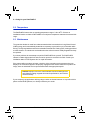
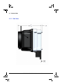
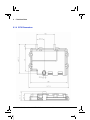
1
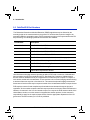
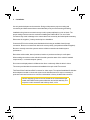
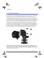
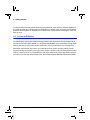
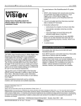
–
User Manual
PathFindIR II
334-0050-00-10, version 100 Feb 2014
i
–
© FLIR Systems, Inc.. All rights reserved worldwide. No parts of this manual, in whole or in part,
may be copied, photocopied, translated, or transmitted to any electronic medium or machine
readable form without the prior written permission of FLIR Systems, Inc.
Names and marks appearing on the products herein are either registered trademarks or trademarks
of FLIR Systems, Inc. and/or its subsidiaries. All other trademarks, trade names, or company names
referenced herein are used for identification only and are the property of their respective owners.
This product is protected by patents, design patents, patents pending, or design patents pending.
FLIR Systems, Inc.
70 Castilian Drive
Goleta, CA 93117
Phone: 1-877-773-FLIR (3547)
www.flir.com
Document: 334-0050-00-10
Version: 100
Date: Feb 2014
ii
Feb 2014 334-0050-00-10, version 100
1 Warnings and Cautions
1.1 Cautions ..........................................................................................1
1.2 General Information ........................................................................2
2 Introduction
2.1 Overview .........................................................................................3
2.2 Thermal Imaging Driver Vision Enhancement System ....................4
2.2.1 PathFindIR II Camera Kit .......................................................5
2.2.2 Installation Kit ........................................................................6
2.3 What is Thermal Imaging? ..............................................................7
2.4 Vehicles that use PathFindIR II .......................................................7
2.5 PathFindIR II Part Numbers .............................................................8
3 Installation
3.1 PathFindIR II Installation .................................................................9
3.2 Preparation and Installation Considerations ....................................9
3.3 Installation Guidelines and Precautions ........................................10
3.4 PathFindIR II Installation ...............................................................12
3.5 ECU Installation ............................................................................14
3.6 Cable Connections ........................................................................15
3.7 Mounting Assistance .....................................................................16
4 Getting Started
4.1 Using your PathFindIR II ...............................................................17
4.2 Initial System Startup ....................................................................17
4.3 Automatic Shutter .........................................................................18
4.4 Heater Element .............................................................................18
4.5 Pedestrian and Animal Detection ..................................................18
4.5.1 Animal Detection .................................................................18
4.5.2 Pedestrian Detection ...........................................................19
4.6 In Case of Difficulty .......................................................................20
4.7 Troubleshooting ............................................................................21
5 Caring for your PathFindIR II
5.1 Product Cleaning ..........................................................................23
5.2 Temperature .................................................................................24
5.3 Maintenance .................................................................................24
6 Technical Data
6.1 Performance Specifications ........................................................25
6.1.1 Side View .............................................................................26
6.1.2 Rear View ............................................................................27
6.1.3 Front View ...........................................................................28
6.1.4 ECU Dimensions .................................................................29
334-0050-00-10, version 100 Feb 2014
iii
iv
Feb 2014 334-0050-00-10, version 100
1
Warnings and Cautions
1.1 Cautions
Caution! This guide uses the term Caution to indicate a potentially
hazardous situation, which, if not avoided, may result in injury, damage
to the vehicle or PathFindIR II, or other property damage.
Caution! The PathFindIR II thermal imaging system will automatically
detect some, but not all, animals and pedestrians. The system is
intended as an early warning for hazards, but it should not be used as the
primary navigation method.
Consult your local and state driving regulations prior to installation.
In many states using active monitors in view of the driver is prohibited. Consult your local and state
driving regulations for laws and guidelines. User assumes all risks and indemnifies the
manufacturer from any liability.
Minimize viewing of the thermal image display while driving.
The PathFindIR II image is intended for occasional viewing, similar to a standard rear view mirror.
Viewing the display may distract the driver from looking ahead and may result in an accident. The
PathFindIR II thermal imaging system should not be used as a substitution for head lamps or head
lamp assisted human vision during vehicle operation.
The PathFindIR II thermal imaging system is designed for commercial, over the road,
automotive applications.
While many other applications are possible, you must carefully consider additional protection and
installation methods that might be required for any given application. Mechanical, environmental
and electrical requirements should be evaluated to assure that the PathFindIR II system can be
utilized with satisfactory results.
When installing the PathFindIR II, do not block the vehicle’s vents or radiator panels.
Doing so may result in heat buildup, equipment breakage, and/or fire.
Do not partake in any activity that takes your attention away from safely driving your
vehicle.
334-0050-00-10, version 100 Feb 2014
1
1 – Warnings and Cautions
Any function that requires your prolonged attention should only be performed after coming to a
complete stop. Always stop the vehicle in a safe location before performing these functions. Failure
to do so may result in an accident.
1.2 General Information
Caution! The PathFindIR II thermal imaging system is not intended to be
used as the primary navigation system. The PathFindIR II should not to
be used as a substitution for head lamps or head lamp assisted human
vision during vehicle operation. It should be used only as an aid to
cautious night-time driving.
Do not open the camera body or the ECU for any reason. Disassembly (including removal of the
cover) can cause permanent damage and will void the warranty.
Operating the camera and ECU outside of the specified input voltage range or the specified
operating temperature range can cause permanent damage.
Do not image extremely high intensity radiation sources, such as the sun, lasers, arc welders, etc.
The camera is a precision optical instrument and should not be exposed to excessive shock and/or
vibration. Refer to paragraph 6.1 “Performance Specifications ” on page 25 for detailed
environmental requirements.
Great care should be used with your camera optics. They are delicate and can be damaged by
improper cleaning. Refer to Chapter 5 “Caring for your PathFindIR II” on page 23.
All thermal imaging systems are subject to export control. Standard NTSC (30Hz) units are
subject to export restrictions and licensing by the United States Government. Models with
video frame rates at or below 9Hz do not require licensing but do require compliance with
other export requirements. Please contact FLIR for details concerning export compliance
for your application or geographic area.
2
Feb 2014 334-0050-00-10, version 100
2
Introduction
2.1 Overview
The FLIR ThermoVision®PathFindIR II is a state-of-the-art thermal imaging system that will provide
you with excellent night visibility and situational awareness, even in absolute darkness.The
PathFindIR II system is designed for simple, intuitive operation and uses sophisticated video
processing algorithms to provide pedestrian and animal detection. The camera is an advanced
thermal sensor that converts thermal content (heat) of a scene into an image for display on a video
monitor inside your vehicle.
Figure 2-1: PathFindIR II Makes the Difference
The above images show a comparison of typical night time driving compared to using the
PathFindIR II thermal imager. The image on the left is from an ordinary camera and shows the
amount of visible light as illuminated by headlights; the image on the right is a thermal image
created by the PathFindIR II thermal imaging camera. The PathFindIR II camera is sensitive to warm
objects, such as the deer, and provides visibility over a much greater distance.
Some of the objects that are most critical for a driver to avoid are people and animals. Because
these objects are naturally warm, they are particularly easy to see with the PathFindIR II and clearly
stand out in the video image. The system automatically highlights detected pedestrians and animals
with yellow boxes to indicate potential hazards.
Many serious accidents occur at night because the driver is not able to see the cause of the
accident in time to prevent the collision. PathFindIR II directly addresses this problem, allowing
drivers to see farther ahead on nighttime roadways and identify potential problems earlier. The
334-0050-00-10, version 100 Feb 2014
3
2 – Introduction
majority of trucking accidents occur in rural areas, where visibility is severely reduced at night.
Humans and other warm blooded animals offer significant thermal contrast to driving backgrounds
and are easy to spot with the PathFindIR II. The system allows drivers to see without any additional
lighting and provides real-time imaging at any speed.
Different than visible light cameras, thermal imagers do not display reflected light as seen with
human eyes. Rather, thermal imaging cameras only 'see' temperature differences which are
converted into shades of grey, from black to white. The PathFindIR II camera displays cold objects
as black and hot objects as white. When using a thermal imager in darkness, the image is created
based on temperature differences of objects in the field of view, rather than reflected light from
headlights. Furthermore, because thermal imaging cameras only 'see' heat sources and not
reflected light, they are ideal to assist with driver vision and situational awareness for oncoming
obstructions such as animals, people, and other vehicles.
2.2 Thermal Imaging Driver Vision Enhancement System
The FLIR Systems, Inc. PathFindIR II system is a high performance, rugged, thermal imaging
camera designed to provide driver vision enhancement in adverse weather conditions and better
situational awareness than with traditional head lamps. The system is comprised of two primary
components: the PathFindIR II camera (or imager), and the Electronic Control Unit (ECU). These
two matched components are the heart of the system. Most installations will also include a video
display (also called monitor), various cables, mounting brackets and mounting hardware.
4
Feb 2014 334-0050-00-10, version 100
2 – Introduction
2.2.1 PathFindIR II Camera Kit
The standard camera kit includes these components:
•
•
•
•
PathFindIR II thermal imager and mounting screws
ECU
PathFindIR II to ECU Cable
Power/Video Cable (Vehicle Power to ECU, ECU video to Display)
PathFindIR Camera
ECU
PathFindIR to ECU Cable
Power/Video Cable
Table 2-1: Standard Camera Kit components
The ECU connects to the vehicle power and interconnects the PathFindIR II to a video display. The
ECU provides power to the camera, controls the camera operation and performs the image
processing for pedestrian and animal detection functions. The ECU outputs the processed image as
analog video so it can be viewed on a display system.
334-0050-00-10, version 100 Feb 2014
5
2 – Introduction
2.2.2 Installation Kit
The optional Installation Kit includes these components:
• SafetyVision Video Monitor, cables, adapters and mounting hardware
• ECU mounting bracket and mounting screws
• Camera mounting bracket and mounting screws
Video Monitor
ECU Bracket (with ECU installed)
PathFinder Mounting Bracket
Table 2-2: Optional Installation Kit components
The Power/Video Cable is 20’ (6m) long and provides flying leads for power and video. It may be
necessary to extend the video cable with an additional video cable to connect to the video display. It
may also be necessary to provide additional power cable to extend to the power source. Refer to
Chapter 3 “Installation” on page 9 for more information.
It is recommended the installer should provide a system On/Off switch and in-line fuse protection.
6
Feb 2014 334-0050-00-10, version 100
2 – Introduction
2.3 What is Thermal Imaging?
With our eyes, we see visible light. With a thermal imager, we can see infrared thermal energy - a
form of light just beyond the visible spectrum. Thermal imagers show subtle differences in
temperature; warm objects appear white and cooler objects appear black.
In addition to driver vision enhancement, FLIR's thermal imaging cameras are used in a wide variety
of applications, including fire fighting, security, maritime, traffic safety, industrial and medical
applications. They continue to be used by militaries worldwide to navigate at night and in battlefield
conditions. Over the last few years, volume production of these systems has allowed FLIR to offer
the same high performance cameras designed for military use to the commercial market.
Although adverse conditions such as heavy fog will affect any driver vision enhancement system,
thermal imaging cameras such as the PathFindIR II have been shown to continue to provide useful
information in conditions of reduced visibility, such as haze and smoke. While the PathFindIR II can
assist drivers with detection of obstructions in the vehicle’s path, thermal imagers should not be
used as the sole vision method of the driver.
PathFindIR II is specifically designed to withstand a harsh environment, with a hermetically-sealed
external housing resistant to rocks, sand, salt, and under-hood contaminants. Additionally, the wide
operating temperature range allows the PathFindIR II to maintain high performance in severe
weather conditions.
2.4 Vehicles that use PathFindIR II
Passenger Vehicles, Commercial Trucks, Buses, and Recreational Vehicles - PathFindIR II can
reduce the detection time for hazards and reduce the probability of an accident - saving lives,
property, and profits.
Emergency Vehicles - Emergency vehicles' high speeds and degraded stopping distances increase
the chance of an accident - PathFindIR II improves hazard detection at high speeds.
Commuter and Freight Trains - PathFindIR II can reveal railway obstructions at long ranges in
complete darkness. This early detection capability can significantly increase reaction time
depending on the size of the obstruction.
Heavy Construction Vehicles - For heavy equipment navigation, PathFindIR II improves awareness
in conditions that render eyesight and daylight cameras useless. The PathFindIR II can see clearly
through dust and smoke, increasing safety for everyone on the job site.
334-0050-00-10, version 100 Feb 2014
7
2 – Introduction
2.5 PathFindIR II Part Numbers
The Pedestrian Detection and Animal Detection (PD/AD) algorithms may be effected by the
mounting height of the camera relative to the ground. For vehicles that require the imager to be
mounted outside the acceptable range, FLIR recommends a version of the system without the PD/
AD processing. The following systems and accessories are available:
Part Number
Description
334-0050-07
PathFindIR II 30Hz, NTSC
334-0054-07
PathFindIR II 7.5Hz, NTSC
334-0052-00
PathFindIR II 30Hz, NTSC, No PD/AD
334-0056-00
PathFindIR II 7.5Hz, NTSC, No PD/AD
421-0053-00
PathFindIR IIInstallation Kit (See “Installation Kit” on page 6)
308-0240-00
PathFindIR II 20 Foot Wiring Harness, Power/Video
261-2319-00
PathFindIR II Camera Mounting Bracket
261-2270-00
PathFindIR II ECU Mounting Bracket
PathFindIR II Replacement Window
Uncooled thermal imaging cameras operating at 30Hz (NTSC) with a resolution of 336x256 and
lower-resolution are export-controlled by the U.S. Department of Commerce. Validated export
licenses must be obtained from the U.S. Department of Commerce prior to export or re-export of
such devices outside of the United States. These restrictions do not control imaging cameras having
a maximum frame rate equal to or less than 9 Hz. This means that thermal imaging cameras with
frame rates of less than 9Hz may be exported outside of the United States without an export license
FLIR employs a team of trade compliance professionals that understand the export rules and
regulations, and can assist customers with their export questions and issues. When FLIR delivers a
camera to a customer in the U.S. who intends to export or re-export the FLIR camera outside of the
United States, whether or not the camera is integrated into another product, it is the customer’s
responsibility to apply for the required export license from the appropriate department of the U.S.
government. Diversion contrary to U.S. law is prohibited.
8
Feb 2014 334-0050-00-10, version 100
3
Installation
3.1 PathFindIR II Installation
The PathFindIR II is a compact, sealed imaging system that fits easily behind vehicle grilles and in
other compact locations. It includes an internal heater to keep the lens clear in icy conditions, and
delivers superior image quality. It can be ordered as a camera module with a commercial grade
cable.
The PathFindIR II should be installed by an installer or dealer trained by FLIR Systems, Inc. If one is
not available in your area we recommend that you use a reputable car audio/video installation shop
that specializes in mobile video system integration. The wiring and installation requires special care
and integration techniques. Improper installation may result in damage to the camera and may void
the warranty.
Some modifications to the vehicle’s exterior may be required, as well as integration into various
display units, including factory LCD or aftermarket multi-functional display units. To allow the cable
from the imager to connect to the ECU, it is necessary to make a hole that penetrates from the
exterior of the vehicle to the passenger compartment. Ensure the cable is adequately protected
from sharp edges and be sure to properly seal the opening once the cable has been installed.
3.2 Preparation and Installation Considerations
The PathFindIR II camera system uses fixed focus optics with a 24° horizontal field of view. The
camera uses a replaceable protective window and an integrated window heater to prevent frost/ice
formation while driving.
In order for the PD/AD functions to work, the camera must be mounted in a specific way. It must be
within a certain range of height from the ground and the forward angle (tilt) must be set within a
certain range, as described in Chapter 3.4 “PathFindIR II Installation” on page 12. For vehicles that
require the imager to be mounted outside the acceptable range, FLIR recommends a version of the
system without the PD/ AD processing.
The ECU housing is a metal enclosure designed to be mounted in the passenger compartment of
the vehicle. To prevent water intrusion or other environmental damage, do not mount the ECU in the
engine compartment or on the exterior of the vehicle.
The PathFindIR II camera must be connected to the ECU with the provided cable. It is not possible
to extend the length of the cable or interconnect multiple cables to extend the distance between the
camera and the ECU.
334-0050-00-10, version 100 Feb 2014
9
3 – Installation
The ECU requires power from the vehicle to operate, and in turn the ECU provides power to the
camera. It is recommended that the ECU should be protected by an in-line fuse and selectively
powered on or off with a switch. The power input requirements are:
• Operating voltage range: 9-16VDC continuously and 18V during 100ms
• Nominal voltage is 13.5VDC
• Maximum system current consumption is 1.8A
The ECU must be properly grounded, as described below. The ECU housing must be grounded to
the vehicle chassis, and the PathFindIR II camera must be isolated from the vehicle chassis. The
optional PathFindIR II Installation Kit provides a means to ground the ECU, and the included camera
bracket, with its non-conductive adjustable ball mount, will isolate the camera as required.
The PathFindIR II must be mounted in a location where it is not obstructed by the windshield or
other glass materials. Although glass is transparent to the human eye, it is opaque in the infrared
spectrum.
It is recommended that power to the monitor should be supplied separately from power to the ECU
to assure clean power (low noise) to both items. Otherwise the video image may appear to have
interference, ghosting, or undesirable video artifacts.
Caution: Before connecting the system, disconnect all power from the
battery. Failure to do so may result in shock, bodily harm, or damage to
system.
3.3 Installation Guidelines and Precautions
It is generally good practice to bench test the camera prior to permanently installing it in the vehicle.
This will allow the installer to become familiar with all of the components, cables, and connectors.
Do not splice cables or tap into existing cables for power or video. Doing so may result in shock, fire,
or damage to electrical system/equipment. Power connections should be made to the fused side of
the vehicle’s power distribution block.
Do not install in areas where the unit will hinder vehicle operation, i.e. radiator, steering, head lamps,
braking systems. Doing so may interfere with the vehicle's operation and cause an accident.
Do not install in areas of high moisture, dust or air intake paths. Doing so may hinder the
performance of the PathFindIR II unit and cause image degradation or window damage.
10
Feb 2014 334-0050-00-10, version 100
3 – Installation
Use only authorized parts and accessories. Doing so helps assure proper mounting and
connectivity and limits external issues associated with poorly secured mounting and wiring.
Installation using incorrect connections may result in system malfunction or risk of shock. The
proper mating connector must be used when installing the PathFindIR II. The use of other
connectors may result in damage to the camera that is not covered by the limited product warranty.
Disconnect the negative (-) battery terminal prior to installation.
Connect the ECU to the vehicle power distribution block using an available fused (2 amp)
connection. Be sure to connect each lead to the correct polarity (red-positive and black-negative).
Be sure to securely mount the system to assure reliable connections and stable system
performance.
Record the serial number, date of purchase, location of purchase and keep in a safe place.
When making connections to the vehicle’s electrical system be aware of the vehicle’s installed
components (i.e. on board computer system).
Do not mount a display where it will distract the driver or adversely affect the driver’s vision.
The screws provided with the camera and installation kit require a #25 Torx wrench.
The Power/Video Cable has a BNC connector for video output. The optional Installation Kit includes
all the adapters needed to connect the system to the included monitor. It may be necessary to
purchase connectors/converters to connect to aftermarket or factory-installed video monitors.
Caution: Supplying power to the unit outside of the recommended and
stated values will result in system malfunction and void the warranty. This
may also result in excessive heat build up, shock, or fire.
334-0050-00-10, version 100 Feb 2014
11
3 – Installation
3.4 PathFindIR II Installation
The imager has 4 mounting holes which accept M5 x 12mm thread-forming screws (included with
the standard system). Do not exceed screw insertion depth of 8-11mm and torque of 4Nm.
The imager should be mounted on the exterior of the vehicle in a high position on the front of the
vehicle, typically in the grille, ideally at a height of 65cm ±15cm from the ground. The position in the
grille from left to right is less important; most installations will mount in the middle or slightly toward
the driver’s side. It is preferred if the imager viewing angle is similar to the driver's viewing angle.
The imager must have a clear optical field of view through the vehicle's grille structure to avoid
obstruction of the scene ahead of the vehicle. One end of the optional Camera Mounting Bracket
connects directly to the back of the imager. The other end can be attached to the grill or other part of
the vehicle, and allows the camera angle to be easily adjusted and set. Alternatively the installer
may wish to fabricate a custom mounting plate or bracket to attach the imager to the vehicle.
The location in the grille should be selected to avoid extreme temperatures or fast temperature
change (e.g. hot air from the engine compartment). Imager location in the grille should be selected
to minimize exposure to road debris, sand abrasion and stone impacts. A higher location is a better
choice to avoid damage to the imager.
12
Feb 2014 334-0050-00-10, version 100
3 – Installation
The alignment between the optical line of sight (LOS) and the center of the image should optimally
be set by the integrator/installer as follows.
• Yaw pointing error: no greater than ±2 degree (center of image to center of
road),
• Pitch pointing error: no greater than ±2 degree (center of image to horizon),
• Roll error: < 1 degree recommended (evaluate subjectively on flat road
surface)
334-0050-00-10, version 100 Feb 2014
13
3 – Installation
3.5 ECU Installation
In most installations, the ECU will be mounted underneath the dashboard, in relatively close
proximity to the video monitor. In most installations, the ECU is secured to the vehicle with the
optional ECU Mounting Bracket and the ECU Mounting Bracket is secured to the vehicle with 4 M5
x 12mm mounting screws (included). The mounting hole diameter for the included screws should
be 4.56/4.48mm (0.179/0.176in).
1 - Screw, Stainless SHC, M3 x 35mm
2 - Screw, Zinc Plt, M5 x 12mm
3 - Screw, (black), M5 x 12mm (qty 3)
As shown in the drawing, a single stainless steel socket head cap screw secures a green grounding
wire and the ECU to the ECU bracket. A single zinc plated pan head screw secures the other end of
the grounding wire to the chassis.
The dimensions of the ECU are approximately 148 x 110 x 24mm (6 x 4 x 1in).
14
Feb 2014 334-0050-00-10, version 100
3 – Installation
3.6 Cable Connections
Run the PathFindIR II to ECU Cable between the camera and ECU, observing that each end of the
cable can only connect to either the camera or the ECU. Connect each end of the cable making sure
the connections are seated securely.
Connect the Power/Video Cable to the ECU connector designated with the Power indication,
as indicated with the black arrow in the image.Do NOT connect the Video/Power cable to the
connector indicated with a red X.
Caution: Be careful to connect the Power/Video cable to the correct ECU
connector. If the cable is connected to the wrong connector and power
is supplied to the ECU, it will result in permanent damage to the ECU
which is not covered under warranty..
Connect the other end of the Power/Video cable as follows:
• Red - VDC+
• Black - VDC• BNC - Video monitor
334-0050-00-10, version 100 Feb 2014
15
3 – Installation
3.7 Mounting Assistance
The following are some general guidelines which will assist your professional service and installer
with good mounting positions and connections.
The PathFindIR II is a thermal imaging system. As such, it will not “see through” windows or
obstructions. The system should be mounted outside the vehicle's cabin (interior) and in such a
location to assure a similar driving viewing field of view as normal head lamps and human vision.
FLIR Systems Inc. is not liable for any modifications made to the vehicle's body, or aftermarket
parts. Owner assumes all risk when modifying vehicles body, frame, grill, or any other structure.
Care should be taken when drilling or cutting into parts. Contact your vehicle manufacture to assure
that the mounting location does not affect the performance, operation, or safety features of your
vehicle.
Mounting should be performed by a FLIR-authorized service center or professional installer of
automotive aftermarket equipment. Many shops familiar with rear vision cameras will be able to
assist in the mounting and location of the PathFindIR II system, as well as proper display mounting
and integration.
Caution: Contact your vehicle manufacture to assure that your mounting
location does not affect any sensors found in bumpers or grills (such as
air bag deployment devices). Mounting the PathFindIR II should never
interfere with the mechanical or electrical components or airways to
maintain vehicle performance or operations.
16
Feb 2014 334-0050-00-10, version 100
4
Getting Started
The thermal imaging camera inside the PathFindIR II is completely sealed and extremely rugged.
The camera has been qualified for operation in all types of weather conditions over the specified
operating temperature range and includes an automatic window heater that will prevent icing under
most conditions.
4.1 Using your PathFindIR II
The PathFindIR II is easy to use, but you should take a moment to carefully read this section so you
understand what is displayed on the video monitor. While the imagery on the monitor may look
similar to black and white daylight video, a few tips on how to interpret the images will help you to
make the most of your system.
The camera automatically adjusts to changing scene conditions so no additional camera control is
necessary. Scenes with familiar objects will be easy to interpret with some experience. The camera
automatically optimizes the image to provide you with the best contrast in most conditions.
The thermal imager inside the camera does not sense light like conventional cameras; it senses
heat or temperature differences. As you experiment with the system during nighttime operation, you
will notice variances in the “picture quality”; this is normal. The camera senses small “differences” in
apparent radiation from the objects in view, and displays them as either white (or lighter shades of
gray) for warmer objects, and black (or darker shades of gray) for colder objects.
4.2 Initial System Startup
The system generally will be in one of three modes:
• Off - system is not powered and not operating
• Startup - the imager displays a FLIR splash screen while it performs the
initialization. The Imager is initially locked until it is authorized by its matching
ECU. The startup takes less than 2 seconds.
• Operating - the imager has been successfully authenticated and is fully
operating providing a thermal image on the video output.
Make sure to test the system prior to installation to assure the system is functioning properly. Be
sure to remove the protective window sticker prior to test and installation.
Upon initial power up, the camera will make a slight clicking sound. This click is the internal image
correction and is entirely normal and expected. This noise is the mechanical shutter assembly
which causes the image to momentarily “freeze.” This noise and image freezing will occur until the
unit has reached a thermally stable temperature and periodically thereafter.
334-0050-00-10, version 100 Feb 2014
17
4 – Getting Started
4.3 Automatic Shutter
The PathFindIR II incorporates an automatic image correction feature via the internal calibration
shutter. This shutter will activate every 2 minutes or more frequently during initial start up and large
environmental temperature changes. During this function the image will be "frozen" for
approximately half a second.
4.4 Heater Element
The PathFindIR II has a built-in heating element to stabilize the window and prevent ice build-up in
cold weather conditions. The heating element is automatically turned on when the temperature of
the window falls below 4ºC and is tuned off when the temperature reaches 6ºC.
4.5 Pedestrian and Animal Detection
The ECU provides a function know as the Vision Processor, which performs three main functions:
• Enhance and adapt the image for the display in the vehicle
• Detect and highlight pedestrians at night
• Detect and highlight animals at night
The system is primarily designed to detect pedestrians and animals at night time. Depending on
conditions and ambient temperatures, the detection algorithms may work poorly or not at all during
the daytime.
4.5.1 Animal Detection
The animal detection is available when the vehicle is in a rural environment. The system is highly
likely to detect an animal correctly if:
• The animal is of the deer family (roe deer, fallow deer, red deer, reindeer,
caribou, moose, cow, horse etc.)
• The animal is in an upright pose
• The animal is moving
• Most of the animal body is visible
The system is highly likely to detect correctly even if:
18
Feb 2014 334-0050-00-10, version 100
4 – Getting Started
• Not all of the animals' legs are visible
• The animal has attributes such as horns or tail, or is carrying objects such as
saddle, saddlebag, collar, leash, necklace and muzzle
• Animals are present in a group or herd. The algorithm most likely detects the
most visible animals (which are not obstructed by others) in the group or the
ones who somewhat separated from the group. Therefore, the animals that
represent the highest risk are detected.
The system is likely to detect correctly, but may give degraded performance if:
• The animal is of the pig family
• The head of the animal is not visible
The system is unlikely to correctly detect an animal if most of the animal body is not visible in the
image. The system may incorrectly detect something as an animal if the structure and heat signature
in the image is similar to the shape and/or heat signature of an animal. Such structures are
sometimes found on various objects, for example warm stones, parts of buildings, parts of vehicles,
street lights, and so on.
4.5.2 Pedestrian Detection
The system is highly likely to detect a pedestrian correctly if:
• The head of the pedestrian is visible.
• The pedestrian is in an upright pose: standing still or moving.
• Most of the body is visible. The system is highly likely to detect correctly even
if other objects such as a vehicle, baby carriage, dog, and so on are close to
the pedestrian.
• Many pedestrians are walking close to each other in a group.
• The object is a cyclist, and the cyclist is in an upright pose similar to a
pedestrian.
The system is not likely to detect correctly if:
• The head of the pedestrian or cyclist is not visible. For example, if the head is
covered by an umbrella or helmet.
• A pedestrian is bending, sitting down, on knees, or lying down. Cyclists
leaning forward on the bike will most likely not be detected correctly.
• Most of the person’s body is obstructed or not visible.
334-0050-00-10, version 100 Feb 2014
19
4 – Getting Started
The system may incorrectly detect something as a pedestrian if the structure and heat signature in
the image is similar to the shape and/or heat signature of a human. Such structures are sometimes
found on various objects, for example parts of vehicle tires, house facades, street lights, or the rear
lights on a car.
4.6 In Case of Difficulty
The PathFindIR II comes with a limited warranty from the date of purchase. Except as describe in
this manual, DO NOT OPEN, MODIFY, or ALTER the PathFindIR II unit or accessories. Doing so will
void any warranty and may cause system malfunction, loss of performance, fire, or bodily harm.
Should the system fail for any reason, do not attempt to fix the system or wiring cables yourself.
Check the wiring connections, power input, video output. If system is not performing please contact
FLIR at +1.888.747.3547 or +1.805.964.9797 and ask to speak to the service department. It will be
necessary to provide the serial number of the unit to obtain a Return Material Authorization (RMA).
20
Feb 2014 334-0050-00-10, version 100
4 – Getting Started
4.7 Troubleshooting
No Video but the system is running and has power supplied to it.
Listen closely to the PathFindIR II unit when it is initally powered on. If you hear the mechanical
shutter (clicking noise, see section 4.2 “Initial System Startup” on page 17) but the camera does not
produce an image, check the video connections. The PathFindIR II works with most standard NTSC
monitors that have 75 ohm componsite (analog) input.
A proprietary authentication scheme is used between the ECU and the PathFindIR II camera. The
ECU and camera combination represents a matched-pair system which is programmed at the
factory. By design, individual camera and ECU components do not operate on their own or when
paired with other components.
No Video, no clicking.
If video is not displayed and you do not hear a “clicking” sound from the PathFindIR II, check the
power inputs. The PathFindIR II runs on 6V to 16V power through the optional 20 foot standard cable
power leads. If this voltage is exceeded the unit will not function and may be damaged.
The image is cloudy or hazy, or the window has fog or ice built up.
The PathFindIR II is equipped with an automatic heating element which turns on at cold
temperatures. The heater requires a few moments to stabilize the window. Once the window is
thermally stabilized the heating element will turn off automatically.
The image has “lines” or screen door appearance.
Check to see if the image “freezes” or if you hear a mechanical “clicking noise” from the PathFindIR
II unit. If you do not see the image freeze momentarily (this may take a few minutes), the internal
shutter may be damaged. Contact the manufacturer.
The image is shaky.
Check your mounting. The PathFindIR II does not incorporate image stabilization and must be
mounted soundly and securely.
Image is dim.
Check your monitor and video connections. It is recommended that you use separate power
supplies for the PathFindIR II and the local display to make sure you have clean uninterrupted
334-0050-00-10, version 100 Feb 2014
21
4 – Getting Started
power. Also, verify the PathFindIR II is connected to the 75 ohm input on the monitor. The image
may be dim if the camera is connected to an input that requires a different impedance.
The image is dark and no objects are seen.
Recycle the power and see if you get the “Splash Screen” (as seen below) on the display. If you get
the Splash Screen but no image afterwards (only a black screen), check to make sure that the
window is clear of all obstructions (refer to the maintenance section for information on window
cleaning). If you do not see the Splash Screen, check the power input and video output.
If you see the Splash Screen but no image afterwards, it is possible the mechanical shutter is stuck
in the on position. Contact FLIR customer service for additional help.
Figure 4-1: Startup Splash Screen
22
Feb 2014 334-0050-00-10, version 100
5
Caring for your PathFindIR II
5.1 Product Cleaning
The PathFindIR II camera images through an infrared transparent window. This window is designed
for the harsh automotive environment of normal driving, but may require occasional cleaning. FLIR
Systems Inc. suggests that you clean the window of the PathFindIR II when image quality
degradation is noticed or excessive contaminant build-up is seen on the window.
The camera housing has a durable coating and the rugged protective window is designed to
withstand normal cleaning. Rinse the camera housing with low pressure fresh water to keep it clean.
If the front window of the PathFindIR II gets water spots, wipe it with a clean soft cotton cloth
dampened with fresh water. If the window requires further cleaning, use a soft moist cotton-based
cloth with isopropyl alcohol or dish soap.
Do not use abrasive materials, such as paper or scrub brushes
as this will possibly damage the window by scratching it. Only
clean the window when you can visually see contamination on
the surface.
The Imager housing is sealed and consists of three parts, a front
part with protective window, internal imager core and rear
housing with the interface connector. The protective window is
made from an IR transparent substrate to optimize thermal
energy throughput and is automatically heated when necessary
to prevent frost or ice formation while driving. The exposed
window surface has a durable Diamond Like Coating (DLC)
coating optimized to resist abrasion.
Depending on the environment, road conditions, the window surface may eventually become visibly
degraded with pits, scratches or other marks. The window element can be replaced with a new
window relatively easily. Contact your local FLIR distributor for information about a replacement
window or other parts and accessories.
Caution! Other than replacing the protective window, do not
disassemble the camera body for any reason. Disassembly of the
camera can cause permanent damage and will void the warranty.
334-0050-00-10, version 100 Feb 2014
23
5 – Caring for your PathFindIR II
5.2 Temperature
The PathFindIR II camera has an operating temperature range of -40 to 80oC. Choose an
installation location so that the PathFindIR II is not subject to temperature extremes that exceed this
range.
5.3 Maintenance
The protective window is made from substrate material that is transmissive to Long Wave Infrared
(LWIR) energy and is automatically heated when necessary to prevent frost or ice formation while
driving. The exposed window surface has a durable Diamond Like Coating (DLC) coating optimized
to resist abrasion. The window is serviceable when the surface becomes visibly degraded and may
be replaced.
If you have problems do not attempt to repair the PathFindIR II unit yourself. The PathFindIR II
camera is a water-tight sealed unit and can not be opened or serviced in the field. Consult your
installation dealer or FLIR Systems Inc. for repair information.
If the camera will not produce an image, check the video connection at the camera and at your
display. If the connectors appear to be properly engaged but the camera still does not produce an
image, have an authorized service representative make the appropriate repairs.
Caution! Improper care of the camera window can cause damage to the
anti-reflective coating, degrade the camera’s performance, and void the
camera warranty.
If your company has applications utilizing a large number of thermal cameras on a specific vehicle
please contact FLIR Systems, Inc. directly to discuss your needs.
24
Feb 2014 334-0050-00-10, version 100
6
Technical Data
6.1 Performance Specifications
Thermal Imaging Performance
Sensor type
Uncooled microbolometer
Field of view
24° h x 18° v
Spectral band
8 - 14 m
Resolution
324 x 256 pixels
Time to Image
< 6 sec.
Focal Length
19 millimeters
Outputs
Video
NTSC
Connector types
4-pin custom automotive connector for power in, video out
Frame Rate
30-Hz Standard, 7.5Hz Export Compliant; Note: Hz is equivalent
to frames per second
Power
Power requirements
12 Vdc nominal (range 6V to 16V)
Power consumption
2 Watts (nominal)
8 Watts with heater turned on
Environmental
Operating temperature
-40º C to +80ºC
The operating temperature range of the ECU is -40C to +80C
when operating in a closed compartment with heat sink to
chassis. In a ventilated area, the heat sink between ECU and
vehicle chassis may be removed, in which case the temperature
range is -40C to +70C.
Ambient temperature, storage:-55°C to +95°C limited by the
environmental temperature diurnal.
Dust and moisture protection:IP69
Impact protection
High-impact resistant window with heating element
Weather Resistance
Hermetically sealed, pressurized enclosure
For additional information, contact FLIR.
Dimensions and Weight
Dimensions
Refer to the following drawings
Weight
less than 0.4 kg (0.88 lb.)
334-0050-00-10, version 100 Feb 2014
25
6 – Technical Data
6.1.1 Side View
26
Feb 2014 334-0050-00-10, version 100
6 – Technical Data
6.1.2 Rear View
The camera mounting holes accept M5 x 12 thread-forming screws (also known as self-tapping
screws). Do not exceed screw insertion depth of 8-11mm and torque of 4Nm.
334-0050-00-10, version 100 Feb 2014
27
6 – Technical Data
6.1.3 Front View
28
Feb 2014 334-0050-00-10, version 100
6 – Technical Data
6.1.4 ECU Dimensions
334-0050-00-10, version 100 Feb 2014
29
FLIR Systems, Inc.
70 Castilian Dr.
Goleta, CA 93117
USA
PH: +1.888.747.FLIR
(+1.888.747.3547)
Document: 334-0050-00-10
Version: 100
Date: Feb 2014