1
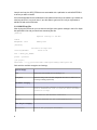
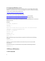
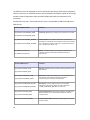
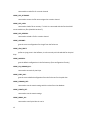
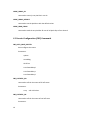
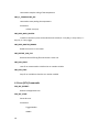
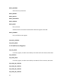
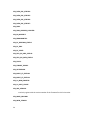
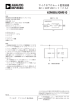
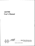
The SPD FED Server Preliminary
Manual
Table of Contents
The SPD FED Server ........................................................................................................................3
1 FED Software................................................................................................................................3
1.1 Libraries Used .......................................................................................................................3
1.2 Development Environment...................................................................................................4
1.3 Solution Dependencies.........................................................................................................5
1.4 Library and DLL Versions.......................................................................................................5
2 FED Installation............................................................................................................................6
2.1 Software Dependencies........................................................................................................6
2.1.1 VISA Drivers Installation and Configuration....................................................................6
2.1.2 Oracle Instant Client Installation....................................................................................6
2.1.3 DIM installation..............................................................................................................7
2.1.4 Jam Player Installation....................................................................................................7
2.2 Installing the Software..........................................................................................................7
2.2.1 Moving the software......................................................................................................7
2.2.2 SPD FED Ini File...............................................................................................................8
2.2.3 Configuring SPD FED as a service...................................................................................9
3 FED Server DIM interface.............................................................................................................9
3.1 FED Commands.....................................................................................................................9
3.2 Status Services....................................................................................................................11
4 List of FED Commands................................................................................................................11
4.1 Half Stave configuration (HSCNF) Commands ....................................................................11
4.2 Generic Configuration (CNF) Commands ............................................................................16
4.3 Scan (SCN) Commands........................................................................................................18
1
4.4 Register Commands............................................................................................................22
4.4.1 Busy card Registers.......................................................................................................22
4.3.2 Link Receiver Registers.................................................................................................23
4.4.3 Router Registers...........................................................................................................25
2
The SPD FED Server
The SPD FED (Front End Device) Server is a stand-alone application designed to be the driver
layer of the system. It interfaces with the SPD electronics and its capable of receiving commands
and of publishing status information to several computers over the network
It was developed in C++ to provide an interface to all hardware features and to be the first layer
of control of the system. Its main purpose is to configure the detector, provide hardware
debugging tools, perform calibration procedures and to publish status information on the system
ensuring the data quality.
There are two instances of the SPD FED servers used in the SPD DCS, one for side A and one for
side C, each one of them being able to freely access the 32 bit VME address space in the
Hardware using a JTAG player embedded in the Router to configure the detector.
SPD
DCS
PVSS
FSM
CU
du
Command
Channel
du
du
Status
Status
Status
FED Server
Dim
Services
SPD
Of f Detector
Electronics
1 FED Software
1.1 Libraries Used
3
Supervision Layer
Nodes
C o nf igu r a tio n
da tab a s e
Ethernet
DIM
FED
SERVER
OCCI
SPD FED
Application Layer
VISA Drivers
VME BUS
Router
Crate
The SPD FED server was developed on top of CERN standard libraries used in its communication
layer and in the hardware access with the detector electronics:
DIM: Developed at CERN stands for Distributed Information Management System. It provides a
network transparent inter-process communication layer. It is used by the SPD FED to publish
status information and to receive commands from other computers through the network.
OCCI: Oracle C++ Call Interface (OCCI) is a high-performance and comprehensive object-oriented
API to access the Oracle databases. It is used by the FED to access the DCS configuration
database.
VISA Drivers: In the Driver layer it uses National Instruments VISA [3] (Virtual Instrument System
Architecture) to interface with the hardware. VISA is a standard which defines I/O software
specifications for VXI (VME eXtensions for Instrumentation), GPIB and serial interfaces.
Links:
Clara Gaspar, DIM; http://dim.web.cern.ch/dim/
OCCI, Oracle C++ Call Interface: http://www.oracle.com/technology/tech/oci/occi/index.html
NI-Visa User Manual: http://www.ni.com/pdf/manuals/321074b.pdf
1.2 Development Environment
The SPD FED server was developed using Microsoft Visual C++ .NET. It is a Visual Studio 2003
solution composed by 6 projects:
ALICE_SPD_DIMServer: Top level project containing the DIM interface to PVSS. This project
parses all FED commands and contains references of all classes
4
HSConfig: Project dedicated to half stave configuration. Contains higher level classes to manage
half staves, routers and calibration scans
AddressGenerator : Contains classes that return memory addresses of the Router, Link Receivers
and of the Busy card
BitsManager: Project dedicated to bitwise operations. Contains a few utility classes that are
passed through inheritance to other classes
spdDbConfLib: Project dedicated to manage the SPD database interface. Contains classes to
connect to the database, to manage all data records with versioning.
VMEAcc: Low level project to manage the VME BUS access. Contains classes to manage the
reading and writing of VME registers as well as VISA sessions
Caution: The development environment was not upgraded to Microsoft’s Visual Studio 2005 or
Visual Studio 2008 due to compatibility problems with ORACLE OCCI interface.
1.3 Solution Dependencies
Here is the diagram of the projects dependencies in the SPD FED server solution.
1.4 Library and DLL Versions
5
Library
Comment
Version
MSVCRTD.DLL
Microsoft Visual Studio 2003 run time
environment
6.0.8797.0
Dim
Dim communication layer version
17r10
Oracle Instant
Client
Oracle interface
10.2.0.1
NiVisa
National Instruments Visa libraries
4.3.0
2 FED Installation
2.1 Software Dependencies
To install the SPD FED server in a machine please make sure to install the following software first
with all environment variables correctly defined.
2.1.1 VISA Drivers Installation and Configuration
You can download the VISA drivers freely from the National Instruments website. They usually
come with LABView, if you install have LABView already installed in this machine you can skip
this installation.
Finally, for the system to work we need to add the router VISA configuration:
Open National Instruments Measurement & Automation and create a new VME device with the
following settings :
System Number
0
Logical Address
300
Slot
1
Mainframe
1
Commander LA
0
VXI A32 Memory Space
0x0 - 0xFF000000
2.1.2 Oracle Instant Client Installation
For the SPD FED server we will need Oracle instant client version 10.2.xx.xx . If this is a DCS
machine at point 2 you can ask the DCS group to install it, they already use the correct version.
If it is not a DCS machine at point 2 then perform the following steps:
6
•
download Instant Client from the Oracle web site:
http://www.oracle.com/technology/software/tech/oci/instantclient/htdocs/winsoft.htm
l
Please choose version 10.2.04 and not higher than this, there are incompatibility problems with
other versions with the Visual Studio 2003 run time environment. The recommended download
is “Instant Client Package - SQL*Plus” if it is a development machine please download also the
SDK.
•
Unzip the instant client to a known location ex: “C:\Oracle\instantClient”
•
Add the database servers that the FED uses to the file tnsnames.ora, you can start by
copying the one from the DFS path: G:\Aplications\Oracle\ADMIN to the instant client
folder. This contains all CERN Oracle servers maintained by the IT department, just check
if your server exists there, if not add it yourself.
•
Configure the environment variables: Add the folder where you extracted the Instant
Client to the “path” environment variable. To be sure that you are using the correct
tnsnames.ora file create a new environment variable called TNS_ADMIN and put there
the path where you have this file (should be the instant client path)
•
If it is a development machine please unzip the SDK to the instant client path and
configure Visual Studio by adding “<instant client path>\sdk\lib\msvc\” to the “libs”
folder list and “<instant client path>\sdk\include\” to the “include” folders
Caution: Usually CERN machines come with “Oracle Tools” installed which comes with an older
version of Oracle instant Client. Please check if you have this installed in your machine and if it is
the case please uninstall it and remove all references from this software from the path
environmental variable.
2.1.3 DIM installation
Download the latest DIM from http://dim.web.cern.ch/dim/dim_wnt.html and follow the
instructions.
If it is a development machine please add the “<dim path>\bin\” to the libs folder list and the
“<dim path>\dim\” to the include folders list.
2.1.4 Jam Player Installation
This is used by the SPD FED server and by LABView software to program the ROUTER FPGAs. Find
a copy of the JamPlayer25.exe Executable and copy it somewhere in the system
ex:”C:\JamPlayer\” . Just remember the path where you have put it, you will need this later.
2.2 Installing the Software
2.2.1 Moving the software
7
Compile and copy the SPD_FEDServer.exe executable with a spdFedIni.ini and MSVCRTD.DLL
to where you want to install it.
If all of the dependencies are installed and in the path environment of the machine you should not
need any other DLL, but just in case, if you don't want to get into a DLL hell you might want to
add dim.dll and oraocci10.dll also.
2.2.2 SPD FED Ini File
After moving the FED server you now need to configure some generic settings in the ini file. Open
the spdFedIni.ini file and you should see something like this:
[General]
#general settings of the FED
side=A
debugMode= false
#debug mode
[DataBase]
# database settings here
conString=DEVDB10
#Fast-Or Db
user = ALICE_DCS_SPDTRG
passwd = pixel456
[jam player]
executable = C:\jp_25\VisualStudio\JamPlayer25\Debug\JamPlayer25.exe
Table with the available categories and settings.
General category
side
Defines which side this FED server is handling: A or C
DebugMode
Defines the debug mode of the FED, debugMode=true means no VME access, so
its running for testing purposes only
DataBase category
conString
Connection string, defines a Oracle database server.
Look at tnsnames.ora file to find out about available
connection strings
User
User name for the database connection
Passwd
Database password for the corresponding user
Jam Player category
Executable
8
Path of the jam player executable
2.2.3 Configuring SPD FED as a service
It is possible to install the SPD FED Server as a Windows Service using a wedge software called
XYNTService, which allows you to run almost any program as a Service on Windows NT, 2000, XP,
or 2003. You can read more about XYNTService on:
http://www.codeproject.com/system/xyntservice.asp
In order to do so, you will need to download two files:
http://www.bitwiseim.com/download/service/XYNTService.exe (the executable)
http://www.bitwiseim.com/download/service/XYNTService.ini (configuration file)
copy these files to the same folder as the SPD FED server, open the XYNTService.ini and write the
following in the file:
[Settings]
ServiceName = SPD_FEDServer
ProcCount = 1
[Process0]
#replace the following items with the correct path to the SPD FED executable
CommandLine = D:\fed_server\SPD_FEDServer.exe
WorkingDir = D:\fed_server\
PauseStart = 1000
PauseEnd = 5000
UserInterface = Yes
Restart = No
Open a command line, go to the path where you copied the SPD FED and run the following
command :
XYNTService -i
And that's it ! please check the windows services and see if you can see a service called
SPD_FEDServer.
To uninstall the service or to restart because of any mistake use the following command :
XYNTService -u
3 FED Server DIM interface
3.1 FED Commands
9
The SPD FED server was designed to receive commands from several ALICE control subsystems.
So for the FED server a command structure was formulated to be flexible, capable of receiving a
variable number of arguments and to accurately display the status of the execution of all
commands.
So each FED server has a “command channel” which is composed by 3 DIM commands and 5
DIM services.
Command DIM Commands
Comment
Spd_feDimServerA/COMMAND_NAME
Command name: A string identifying the command to be executed
Spd_feDimServerC/COMMAND_NAME
spd_feDimServerA/CHANNEL_NUMBER
spd_feDimServerC/CHANNEL_NUMBER
spd_feDimServerA/DATA_IN
spd_feDimServerC/DATA_IN
Channel number: The channel number of the command to be
executed, this corresponds to the half-stave number. If the command
is for a Router then channel number 0 to 5 corresponds to Router 0,
6 to 11 corresponds to Router 1 etc…
Data In: A variable length array containing the input data of the
command. The format of the data will depend of the type of
command sent.
Command DIM Services
Comment
spd_feDimServerA/RET_DATA
Data Out: Variable length array with the resulting output data of the
last command
spd_feDimServerA/RET_DATA
spd_feDimServerA/ERROR_CODE
spd_feDimServerC/ERROR_CODE
spd_feDimServerA/ERRORS_REPORT
spd_feDimServerC/ERRORS_REPORT
spd_feDimServerA/CMD_NAME
spd_feDimServerC/CMD_NAME
spd_feDimServerA/CH_NUMBER
10
Error Code : Integer value displaying the execution status of the
last command, 0 if executed successfully and with the
corresponding error code if the execution failed
Error Report : A string displaying with a more meaningful
information of the execution status of the last command ex:
“HSCNF_CONFIGURE_DEF failed for channel 12”
Command Name Return: DIM service updated by the FED server
after the execution of a command. Returns back the received
command name.
Channel Number Return: DIM service returning back the channel
number received.
spd_feDimServerC/CH_NUMBER
3.2 Status Services
Connecting the SPD hardware to the rest of the world the SPD FED server has to work also as
one information hub of the system. Data that are relevant to the overall stability of the
system need to be constantly monitored and passed quickly to the PVSS supervision layer for
monitoring purposes and Alarm generation. So in addition of the data that can be retrieved
trough commands both SPD FED servers publish a list of several parallel DIM Services
displaying extra information of the system.
Status DIM Services
Comment
spd_feDimServerA/TEMP_BUS<000..059>
Temperature of the bus: 120 DIM services, one per halfstave, displaying the detector bus temperature measured by
the Router.
spd_feDimServerC/TEMP_BUS<060..119>
spd_feDimServerA/TEMP_MCM<000..059>
spd_feDimServerC/TEMP_MCM<060..119>
spd_feDimServerA/ROUTER_ERROR<0..9>
spd_feDimServerC/ROUTER_ERROR<10..19>
spd_feDimServerA/LOG
Temperature of the bus: 120 DIM services, one per halfstave, displaying the detector MCM temperature measured by
the Router.
Router Error Status : 20 DIM services, one per Router,
displaying the number of errors detected by the Router FPGA
in the system
DIM Log Interface : String DIM service publishing log
information of each FED , very useful for debugging purposes
spd_feDimServerC/LOG
spd_feDimServerA/DATA_STREAM
spd_feDimServerC/DATA_STREAM
Data Stream: DIM service that can publish the raw data
stream of the detector enabling the use separate analysis tool
without the need of the ALICE Data Acquisition Systems
4 List of FED Commands
4.1 Half Stave configuration (HSCNF) Commands
HSCNF_ACTUALS_TO_FILE:
command to dump all actual settings to file, it will generate 60 files in the folder '' with
the name actualHS001.txt, actualHS002 etc
11
HSCNF_API__DACDEF:
command to set the dacs in the analog pilot with the default values
HSCNF_API__READ:
command to read the dacs in the analog pilot
Returns:
array with analog pilot values 0: Dac Ref High, 1: Dac ref mid, 2: Gtl Ref A, 3: gtl ref D,test
high,5: test low
HSCNF_API__READADC:
command to read the adcs in the analog pilot
Returns:
analog pilot ADCs
HSCNF_API__SET_ONE_DAC:
command to set only one dac of the analog pilot
Parameters:
dac
number (follows the same order as in the jtag scan)
dac
value
HSCNF_API__SETDAC:
command to set the dacs in the analog pilot
HSCNF_APIDAC:
gets the current default configuration from the fed server for the analog pilot dacs
HSCNF_CONFIGURE_DEF:
command to configure an halfstave with the default values, DPI, API and DACS
Returns:
bit 0 is enabled if it fails in the jtag reset, bit 1 if it fails setting the digital pilot, bit 2 if it
fails the analog pilot setting, 3 if it fails the pixel dacs settings
HSCNF_CONFIGURE_DEF_ALL:
12
command to configure all of the halfstaves with the default values
Returns:
an array with 60 elements each one with the status of the configuration (it 0 is
enabled if it fails in the jtag reset, bit 1 if it fails setting the digital pilot, bit 2 if it fails the analog
pilot setting, 3 if it fails the pixel dacs settings)
HSCNF_DATA_RESET_ALL:
command to set the digital pilot internal settings with the default values in all enabled
halfstaves
HSCNF_DB_COMPARE:
command to compare the data in the default containers and actual containers in the fed
and save it to the temporary table in the database
HSCNF_DB_DIFF_COUNT:
command to count the diferences between the data in the default containers and actual
containers in the fed
Returns:
McmDifferences, DacDifferences, NoisyDifferences
HSCNF_DB_GET:
command to get the current configuration of the detector from the database
HSCNF_DB_GET_GLOBAL_VERSION:
command to return the current database global version loaded in the FED
HSCNF_DB_GET_MASK_VERSION:
command to return the current mask (noisy pixels) version assigned to this fed server
HSCNF_DB_GET_SIDE_VERSION:
command to return the current database side version assigned to this fed server
HSCNF_DB_LINK:
command to link the two side versions of each fed in the global version in the database
13
HSCNF_DB_MASK:
command to mask the full detector with the data from the database
Parameters:
versionNumber
HSCNF_DB_SET:
command to save the current configuration of the detector in the database
HSCNF_DEFAULTS_TO_FILE:
command to dump all default settings to file, it will generate 60 files in the folder '' with
the name defaultHS001.txt, actualHS002 etc
HSCNF_DPI_DEF:
command to set the digital pilot settings with the default values
HSCNF_DPI_INT_DEF:
command to set the digital pilot internal settings with the default values
HSCNF_DPI_INT_DEF_ALL:
command to set the digital pilot internal settings with the default values in all enabled
halfstaves
HSCNF_DPI_INT_SET:
command to set the digital pilot internal settings
HSCNF_DPI_READ:
command to read the digital pilot settings
HSCNF_DPI_SET:
command to set the digital pilot settings
HSCNF_DPICONF:
gets the current default configuration from the fed server for the digital pilot
HSCNF_FILE_GET:
14
command the read a file for a certain channel
HSCNF_FILE_GETNAME:
command to return the file name assigned to a certain channel
HSCNF_FILE_LOAD:
command to load a file to memory !? I think it is connected with the fact that PVSS
cannot read binary files (should it be there!?)
HSCNF_FILE_REFRESH:
command to reload a file for a certain channel
HSCNF_GOLCONF:
gets the current configuration for the gol from the fed server
HSCNF_JTAG_RESET:
performs a jtag reset in the halfstave, its a IR scan only with IR code 0xb for the pixel
chips
HSCNF_NOISYPIX:
gets the default configuration in the fed memory (from configuration file only)
HSCNF_PIX_UNMASK_ALL:
command to unmask all pixel chips
HSCNF_PIXEL_DAC:
gets the current default configuration from the fed server for the pixel dacs
HSCNF_PIXMASK_DEF:
command to set the matrix settings with the values from the database
HSCNF_PIXMTX_SET:
command to set the matrix settings
HSCNF_PXDAC_ALL:
command to set all pixel dacs in one hs
15
HSCNF_PXDAC_CH:
command to set only one pixel dac in one hs
HSCNF_PXDAC_DEFAULT:
command to set the pixel dacs with the defualt values
HSCNF_READ_PXDAC:
command to read the one pixel dac for one all 10 pixel chips of one channel
4.2 Generic Configuration (CNF) Commands
CNF_AUTO_CONF_ROUTER:
Auto configures the router.
Parameters:
options
controlReg
L0L1Time
LrxL1FastorDelay0
LrxL1FastorDelay1
LrxL1FastorDelay2
CNF_CHSTATUS_ALL:
command to refresh the status of all half staves
Parameters:
array
with 120 values
CNF_CHSTATUS_CH:
command to refresh the status of one half stave
Parameters:
16
value
0: off, 1 on, 2 test
CNF_MCMSTIMULI_OFF:
command to clear the mcm stimuli in one channel
Parameters:
channelNumber
columnToSet
CNF_MCMSTIMULI_OFF_ALL:
command to clear the mcm stimuli in all enabled channels
Parameters:
columnToSet
CNF_MCMSTIMULI_ON:
command to set the mcm stimuli on in one channel
Parameters:
channelNumber
columnToSet
CNF_MCMSTIMULI_ON_ALL:
command to set the mcm stimuli on in all enabled channels
Parameters:
columnToSet
CNF_PL_RT_ERRORS_START:
Starts pooling the router memory for errors.
CNF_PL_RT_ERRORS_STOP:
Stops pooling the router memory for errors.
CNF_PL_TEMPERATURE_OFF:
17
command to stop the ooling of the temperature
CNF_PL_TEMPERATURE_ON:
command to start pooling the temperature
Parameters:
refresh time (ms)
CNF_READ_BUSY_ROUTER:
reads the router busy times and sends them all to PVSS, 0 = busy daq, 1= busy router, 2 =
busy HS, 3 = busy trigger
CNF_READ_ROUTER_ERRORS:
Reads the error list in one router.
CNF_RESTART_LOG_FILE:
Renames the old FED log file and restarts a clean one.
CNF_RUN_START:
start of run commmand to initialize the run number variable
CNF_RUN_STOP:
Stop of run variable to clean the run number variable.
4.3 Scan (SCN) Commands
SCN_DAC_RESTART:
Restarts a stopped dac scan.
SCN_DAC_START:
Starts dac scan.
Parameters:
TirggerNumber
dacMin
18
dacMax
steps
dacNumber
InternalTrigger
WaitTime
SCN_DAC_STOP:
stops a dac scan
SCN_DELAY_RESTART:
Restarts a stopped delay scan.
SCN_DELAY_START:
Starts a delay scan.
Parameters:
TirggerNumber
delayMin
delayMax
steps
InternalTrigger
WaitTime
SCN_DELAY_STOP:
stops a delay scan
SCN_FO_SCAN_START:
Starts a fastor calibration scan.
Parameters:
fopolMinimum
19
fopolMaximum
fopolStep
convpolMinimum
convpolMaximum
convpolStep
comprefMinimum
comprefMaximum
comprefStep
cgpolMinimum
cgpolMaximum
cgpolStep
prevthMinimum
prevthMaximum
prevthStep
NumberOfTriggers
Matrices
SCN_FO_SCAN_STOP:
stops a fastor calibration scan
SCN_FO_SCAN_TEST:
Used only to debug a fastor scan, performs one single step of this scan.
SCN_MEANTH_RESTART:
Restarts a stopped mean threshold calibration scan.
SCN_MEANTH_START:
Starts a Mean threshold calibration scan.
20
Parameters:
dacMin
dacMax
Steps
startRow
endRow
rowStep
triggerNumber
SCN_MEANTH_STOP:
Stops a Mean threshold scan
SCN_MINTH_RESTART:
Restarts a stopped minimum threshold scan.
SCN_MINTH_START:
Starts a minimum threshold delay scan.
Parameters:
TirggerNumber
pre_vthMin
pre_vthMax
steps
InternalTrigger
WaitTime
SCN_MINTH_STOP:
stops a minimum threshold scan
SCN_NOISE:
21
Starts a noise scan.
Parameters:
TirggerNumber
InternalTrigger
SCN_NOISE_STOP:
stops a noise scan
SCN_UNIFORMITY_RESTART:
SCN_UNIFORMITY_START:
Starts a Uniformity matrix scan.
Parameters:
TriggerNumber
StartRow
EndRow
MaskNoActivePixels
SCN_UNIFORMITY_STOP:
Command to stop an active uniformity scan
4.4 Register Commands
The following are commands related to router, link receiver or Busy card commands
register . These are always 32 bit registers, the functionality will depend of the
register itself, please check the device documentation for further information.
Important: Please add a “R_” to the beginning to the command if you want to read
or a “W_” if you want to write in the register ex: “R_BSYCD_BUSYMASK” to read busy
card mask register and “W_BSYCD_BUSYMASK” to write in the busy card register.
4.4.1 Busy card Registers
BSYCD_BUSYMASK:
Writes the busy card mask register
BSYCD_CNCOUNTERS:
22
BSYCD_CONTROL:
Writes the busy card control
BSYCD_DRVREC:
BSYCD_INPUTS:
BSYCD_L0COUNTER:
BSYCD_L0DELAY:
BSYCD_RESET:
Busy card reset
Definition file for commands associated with read-write register commands
BSYCD_VERSION:
busy card FPGA version register
LRX_BUSY_CONTROL:
LRX_BUSY_MASK:
4.3.2 Link Receiver Registers
LRX_CLK_DELAY:
write only register, its used to set the delay in the clock line for this channel, 8 bits value
LRX_CONTROL:
LRX_DATA_DELAY:
write only register, its used to set the delay in the data line for this channel, 8 bits value
LRX_DATA_ENC_STATUS0:
LRX_DATA_ENC_STATUS1:
LRX_DATA_ENC_STATUS2:
LRX_DATA_ENC_STATUS3:
23
LRX_DATA_ENC_STATUS4:
LRX_DATA_ENC_STATUS5:
LRX_DATA_ENC_STATUS6:
LRX_DATA_ENC_STATUS7:
LRX_DPM:
LRX_DPM_ADDRESS_COUNTER:
LRX_EN_MOVEBIT:
LRX_ERROCOUNTER:
LRX_EV_DESCRAM_STATUS:
LRX_EV_END:
LRX_EV_START:
LRX_FIFO_EV_DATA_STATUS:
LRX_FIFO_PIX_DATA_STATUS:
LRX_FLUSH:
LRX_FORMAT_ERROR:
LRX_HISTOGRAM:
LRX_INPUT_ST_STATUS0:
LRX_INPUT_ST_STATUS1:
LRX_L1_MEM_POINTER:
LRX_L1_ROUT_COUNT:
LRX_LRX_VERSION:
read only register with the version number of the firmware for this link receiver
LRX_MASK_COLUMN:
LRX_MCM_STIMULI:
24
LRX_MEM_END:
LRX_MEM_START:
LRX_RESET:
LRX_SHIFT_SEL:
LRX_SOFT_RESET:
LRX_STATUS:
LRX_TEMPERATURE:
LRX_TEST_REG:
4.4.3 Router Registers
RT_ADDRESS_MEM_COUNTERS_SELECTED:
new michele register
RT_BC_CLOCK_LOCK:
Clock Fine Delay, makes the router lock to one of the bunch crossing orbits, write and
read register with 2 bits with the follow format: Clock_phase_fine_delay[0],
Clock_phase_fine_delay[1].
RT_CONTROL:
Base address of the router control register (this one is used every time).
RT_DATA_RESET:
RT_DATA_SELECT:
RT_DDL_STATUS:
RT_DPM:
Base address of the dual port memory (read only).
RT_ERROR_MANAGER_RESET:
Error handler Global RESET (for all FSMs and SPM).
RT_ERROR_MASK:
25
Command to access the router error mask register.
RT_EV_LENGTH_OF_BLOCK:
RT_FIFO_ENDADDR:
RT_FIFO_STARTADDR:
RT_FLUSH_DPM:
RT_FO_COINCIDENCE_COUNTER:
RT_FO_FROMVME:
RT_FO_GLOBAL_COUNTER:
RT_FO_LINKRX_COUNTER:
RT_FO_NUMBER:
RT_FO_TIME_COUNTER:
RT_INTERLOCK_STATUS:
Read_interlock_Status_selected = (areg =='hf4) --> only read, you received 7 bits with
the following format: Router_Interlock Interlock on HS_5 Interlock on HS_4 Interlock on HS_3
Interlock on HS_2 Interlock on HS_1 Interlock on HS_0.
RT_IRQPUSHB:
RT_JPLAYER:
RT_JT_EXEC_START:
RT_JT_RDEN_FIFOIN:
RT_JT_RDNUMB_FIFOIN:
RT_JT_RDWR_DATA:
RT_JT_RESET_CH:
RT_JT_RESET_FIFO:
RT_JT_RESET_STMACHINE:
RT_JT_STATUS:
26
RT_L0_COUNTER:
new michele register
RT_L0ID:
RT_L1ID:
RT_L2ID:
RT_LRX_MEM_BASEADDR:
Base address of the dual port memory in the link receiver : Must be debugged, never
used and there are 6 memories per router(2 per lrx) but the software only returns one (we have
a clear bug here).
RT_MEM_COUNTERS:
new michele register
RT_NUM_TRANS_BUSY_DAQ:
new michele register
RT_NUM_TRANS_BUSY_HS:
new michele register
RT_NUM_TRANS_BUSY_ROUTER:
new michele register
RT_NUM_TRANS_BUSY_TRIGGERS_L1_FIFO:
new michele register
RT_RD_EV_START:
RT_RDHISTO:
For the moment this feature is disabled, the link receiver does not have histogram mode
anymore.
RT_REGISTER:
function to access a register inside the router
RT_RESET_BUSYRESOLVER:
27
new michele register
RT_RESET_DETECTOR:
RT_RESET_HS:
RT_RESET_LRX:
RT_RESET_PIXEL:
RT_RESET_TTC:
RT_RST_TEMPLIM:
RT_RSTBNC:
RT_RXREADY:
new michele register
RT_SCOPE_SELECTOR0:
RT_SCOPE_SELECTOR1:
RT_SCOPE_SELECTOR2:
RT_SELECT:
RT_SEND_TRIGGER:
RT_SPM:
Base address of the single port memory (read only).
RT_STATUS1:
RT_STATUS2:
RT_STATUS3:
RT_STATUS_JTAG_SELECT:
RT_STATUS_LINKRX0:
RT_STATUS_LINKRX1:
RT_STATUS_LINKRX10:
28
RT_STATUS_LINKRX11:
RT_STATUS_LINKRX12:
RT_STATUS_LINKRX13:
RT_STATUS_LINKRX14:
RT_STATUS_LINKRX15:
RT_STATUS_LINKRX2:
RT_STATUS_LINKRX3:
RT_STATUS_LINKRX4:
RT_STATUS_LINKRX5:
RT_STATUS_LINKRX6:
RT_STATUS_LINKRX7:
RT_STATUS_LINKRX8:
RT_STATUS_LINKRX9:
RT_TEMPERATURE:
RT_TEMPERATURE_LIMIT_BUS:
RT_TEMPERATURE_LIMIT_MCM:
RT_TIME_BUSY_DAQ:
new michele register
RT_TIME_BUSY_HS:
new michele register
RT_TIME_BUSY_ROUTER:
new michele register
RT_TIME_BUSY_TRIGGERS_L1_FIFO:
new michele register
29
RT_TIME_L0L1:
RT_TP_L1_DELAY:
Configurable Test pulse L1 delay, like this calibration scans and data taking scans can
have the same delay setting in the pixels.
RT_VERSION_NUMBER:
'RT_VERSION' is already defined in winUser.h file, an old windwos file that we don't want
to mess for sure
RT_VMERESET:
RT_WRHISTO:
30