1
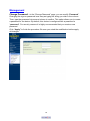
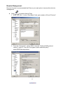
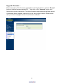
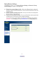
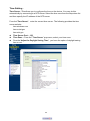
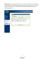
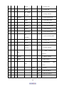
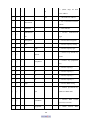
Broadband Wireless Connectivity Solution ALINK-PW5 Pre-WiMAX Revision 1.0 User Guide 1 U Revision History Version Date Notes 1.0 Aug. 24, 2009 Initial Version 2 The Wireless Technology Broadband Wireless Connectivity Solution The Product line are adopting Wireless TDMA concept to provide an affordable and reliable rural connectivity platform. All of products are high performance outdoor deployable wireless bridge that provides wireless connectivity between multiple network locations. With the high throughput and long distance transmission, it is the appropriate backhaul solution for Network Carriers, Internet Service Providers, System Integrators and Enterprises. About this manual The purpose to use this manual is for install the Pre-WiMAX capacity Wireless TDMA Backhaul. This user manual is including disposing course and method and helping the customer to solve the unpredictable problem. The following typographical conventions are used in this purpose: U Planning Your Wireless Network Network Topology A wireless network is a group of computers, each equipped with one wireless adapter. Computers in a wireless network must be configured to share the same radio channel. Several PCs equipped with wireless cards or adapters can communicate with one another to form an ad-hoc network. The wireless adapters also provide users access to a wired network when using an access point or wireless router. An integrated wireless and wired network is called an infrastructure network. Each wireless PC in an infrastructure network can talk to any computer in a wired network infrastructure via the access point or wireless router. An infrastructure configuration extends the accessibility of a wireless PC to a wired network, and may double the effective wireless transmission range for two wireless adapter PCs. Since an access point is able to forward data within a network, the effective transmission range in an infrastructure network may be doubled. Network Layout The Wireless Bridge has been designed for use with proprietary 5 GHz based on IEEE 802.11a standard products, products using these standards can communicate with each other. When you wish to connect your wired network with your wireless network, the Wireless Bridge’s network port can be used to connect to any of switches or routers. 3 Installation Considerations The AP lets you access your network, using a wireless connection, from virtually anywhere within its operating range. Keep in mind, however, that the number, thickness and location of walls, ceilings, or other objects that the wireless signals must pass through, may limit the range. Typical ranges vary depending on the types of materials and background RF (radio frequency) noise in your home or business. The key to maximizing wireless range is to follow these basic guidelines: Keep your product away (at least 3-6 feet or 1-2 meters) from electrical devices or appliances that generate RF noise. Keep the number of walls and ceilings between the AP and other network devices to a minimum - each wall or ceiling can reduce your AP’s range from 3-90 feet (1-30 meters.) Position your devices so that the number of walls or ceilings is minimized. Be aware of the direct line between network devices. A wall that is 1.5 feet thick(.5 meters), at a 45-degree angle appears to be almost 3 feet (1 meter) thick. At a 2-degree angle it looks over 42 feet (14 meters) thick! Position devices so that the signal will travel straight through a wall or ceiling (instead of at an angle) for better reception. Building materials can impede the wireless signal - a solid metal door or aluminum studs may have a negative effect on range. Try to position wireless devices and computers with wireless adapters so that the signal passes through drywall or open doorways and not other materials. Applications The wireless LAN products are easy to install and highly efficient. The following list describes some of the many applications made possible through the power and flexibility of wireless LANs: Difficult-to-wire environments There are many situations where wires cannot be laid easily. Historic buildings, older buildings, open areas and across busy streets make the installation of LANs either impossible or very expensive. Temporary workgroups Consider situations in parks, athletic arenas, exhibition centers, disaster-recovery, temporary offices and construction sites where one wants a temporary WLAN established and removed. The ability to access real-time information Doctors/nurses, point-of-sale employees, and warehouse workers can access real-time information while dealing with patients, serving customers and processing information. Frequently changed environments Show rooms, meeting rooms, retail stores, and manufacturing sites where 4 frequently rearrange the workplace. Wireless extensions to Ethernet networks Network managers in dynamic environments can minimize the overhead caused by moves, extensions to networks, and other changes with wireless LANs. Wired LAN backup Network managers implement wireless LANs to provide backup for mission-critical applications running on wired networks. 5 Network Topology – Wireless Bridge (PEER-TO-PEER) Point 6 Installation Diagram Attention: The cable distance between the Router and PC/hub/Switch should not exceed 100 meters. Make sure the wiring is correct. In 10Mbps operation, Category 3/4/5 cable can be used for connection. To reliably operate your network at 100Mbps, you must use Category 5 cable, or better Data Grade. 7 Wireless Bridge Configuration Using Web User Interface Before Setup… Verify the IP address setting You need to configure your PC’s network settings to obtain an IP address. Computer use IP addresses to communicate with each other across a network, such as the Internet. 1. From the taskbar, click the Start button, select Settings > Control Panel. From there, double-click the Network connections icon. Right click the Local Area Connection icon Properties; select the TCP/IP line for the applicable Ethernet adapter. Then, click the Properties button. Click the IP Address tab page, select USE the following IP address, type 192.168.1.254 (but, 192.168.x.x for the device use) in the IP Address field and 2. 3. 255.255.0.0 in the Subnet Mask field, then click OK button. Start Setup by Browser... 1. After getting the correct connection, start the web browser (make sure you disable the proxy) and type 192.168.x.x (x is outdoor unit IP Address) in the Address field. Press Enter. You will see a popup menu below: Clicking “Yes” ushers you into login. 2. Enter the factory default User name and Password fields: User Name: admin Password: password then click Login button. 8 3. You will enter the Utility homepage. Device Information The first page appears in main page will show “Device Information” automatically, you can find the Device Name, MAC address, Firmware version. Basic Setup Device Name – You’ll see the Device Name. You may assign any device name to this CPE. This name is only used by the CPE administrator for identification purposes. Unique, memorable names are helpful, especially if you are employing multiple access points on the same network. This name is composed of 15 characters with 0-9, A-Z, a-z or “-“. Ethernet Data Rate – 10/100 Mbps Base-T 9 IP Address – IP Address – Default is “Manual” or set to DHCP IP Subnet Mask – Default Gateway – Primary DNS Server – Secondary DNS Server – Spanning Tree Protocol (STP) –Spanning-Tree Protocol is a link management protocol that provides path redundancy while preventing undesirable loops in the network. 10 Wireless Setup Radio Frequency (RF) – Default is “Enable” Remote MAC Address –Wireless Bridge (Peer-to-Peer) can allow Bridge point to point network architecture, In order to establish the wireless link between bridge radios, the MAC address of remotes bridge(s) need to be registered in the address table. Type the MAC address with format xx:xx:xx:xx:xx:xx (x is the hexadecimal digit) Security – Cipher – Default is “NONE”, WEP and AES Cipher Phrase – 11 Radio RF Bandwidth –Optimize the network and increase its bandwidth, the options are 5,10, 20 and 40MHz, default is 20MHz - Channel/Frequency –The channels available are based on select the appropriate channel from the list provided to correspond with your network settings. 12 - TX Rate Range –In data rate column you can select all bit rate supported in current operation mode. Default value is “BPSK 1/2 to 64QAM 3/4” means the system will adjust the connection speed dynamically according to your current link status. - TX Power – Default is “full”, you can reduce RF output power by selecting adjustable transmit power full, half, quarter, eighth and min. To change transmit power may decrease your wireless signal coverage. This feature can be helpful in restricting the coverage area of the wireless network. 13 - Antenna – Default setting is “Fixed on Primary”, if you need “Tx on Primary; Rx on Secondary” option for customization and contact to our sales window for special deliver. 14 Status Peer-to-Peer link show the Bridge ID of neighborhood, Time, MAC address, IP Address, Channel Info. ,Rx/Tx rate, RSSI (dBm), Remote RSSI, Best Remote RSSI (dBm) and Status Statistics – 15 Management Change Password –In the “Change Password” page, you can modify “Password”. Changing the sign-on password is as easy as typing the string you wish in the column. Then, type the password into second column to confirm. This option allows you to create a password for the device. By default, this device is configured with a password is “password”. For security reasons it is highly recommended that you create a new password. Click “Apply” to finish the procedure. Be sure you noted the modification before apply all changes. 16 Remote Management – Remote Console is recommended that Putty is your right option to access this device’s management. Open by double clicking Putty 1. Enter 192.168.1.1 in the “Host Name” field, port number is 22 and “Protocol”. 2. From the “Connection”, select “SSH”; from the “Preferred SSH protocol version”, select“2”; from the “Encryption cipher selection policy”, make“3DES”the top position. 17 3. Click Open and a page will open like below: 4. Enter username: admin and password: password in the separate field 5. For Help information, enter “help” command. Under System Management, click SNMP to display and change settings for the Simple Network Management Protocol. To communicate with the access point, the SNMP agent must first be enabled and the Network Management Station must submit a valid community string for authentication. Select SNMP Enable and enter data into the fields as described below. When you are finished, click “Apply” 18 Setting Description SNMP Enables or disables SNMP. Contact Location Sets the location string that describes the system location. Maximum length is 255 characters. Community Name (Read Only) Specifies a community string with read-only access. Authorized management stations are able to retrieve MIB objects. Maximum length is 32 characters. Default is “public” Community Name (Read Write) Specifies a community string with read-write access. Authorized management stations are able to both retrieve and modify MIB objects. Maximum length is 32 characters. Default is “private” Trap Destination Enter the IP address of the trap manager that will receive these IP Address messages. Trap Destination Community Name Enter the community name of the trap manager that will receive these messages. Default is “public” 19 Upgrade Firmware – Enter the location of the firmware upgrade file in the file path field, or click the “Browse” button to find the firmware upgrade file. Then click on the “Upgrade” button, and follow the on-screen instructions. The whole firmware upgrade process will take around 60 seconds. Before upgrade, make sure you are using correct version. Please check with your technical support service if new firmware available. 20 Backup/Restore Settings – In Management section, you can Backup/Retrieve Setting and Restore to Factory Default Settings the system in following pages. Backup the current settings to a file – Click on the “Backup” button, system will prompt you where to save the backup file. You can choose the directory to save your configuration file. Retrieve backed up settings from a file – Here you can restore the configuration file from where you previous saved. Restore to factory default settings – Be very carefully before restore system back to default since you will lose all current settings immediately. If you act the function, the IP address will restore the establishing value situation. 192.168.1.1 in the IP Address field and 255.255.255.0 in the Subnet Mask field, 21 Time Setting – Time Server –This allows you to configure the time on the device. You may do this automatically by connecting to a NTP server. Select the time zone from the drop down list and then specify the IP address of the NTP server. From the“Time Server”,enter the correct time server. The following provides the time server website. time.windows.com time-a.nist.gov time.nist.gov Time Server Port – 123 Time Zone – From the” Time Server ”pop-menu, select your time zone. From the“Adjust for Daylight Saving Time”,you have the option of daylight saving time or not. 22 Event Log –The Log page displays a list of events that are triggered on the Ethernet and Wireless interface. This log can be referred when an unknown error occurs on the system or when a report needs to be sent to the technical support department for debugging purposes. 23 Reboot –Click on “Yes” button to restart Bridge and wait 30 seconds for system rebooting. Logout– 24 Appendix A: Specification Standards Compliance SDRAM Flash Radio Frequency Type Modulation Frequency Band Transmission Power Data Rate Access Point Interfaces Sensitivity Antenna Type Security Systems Wireless Setting Software/Firmware Operating Environment Power Network Management System OS Support Warranty IEEE 802.11 silicon to non-standard; IEEE 802.3; IEEE 802.3u; IEEE802.3af(option) 64 M Byte 16M Byte Proprietary 5GHz based on 802.11a OFDM 64QAM 3/4, 64QAM 2/3, 16QAM 3/4, 16QAM 1/2, QPSK 3/4, QPSK 1/2, BPSK 3/4, BPSK 1/2 5120~6060MHz 300mW ( Adjustable output power ) Up to 40Mbps over 50Km connection Auto sensing MDI/MDI-X Ethernet 10/100Base-TX: RJ-45 -92dBm @ 6Mbps; -72dBm @ 54Mbps, PER < 10% N-type external high gain antenna WEP/ AES encryption; Operation Mode –Wireless PtP Bridge Channel Bandwidth adjustable 5/10/20/40 MHz Adjustable transmit power DFS Spanning Tree settings Reset to default by WebUI Web-based configuration via popular browser (MS IE, Netscape…) Firmware upgrade and configuration Backup/Restore via Web 802.1Q VLAN pass-through Signal strength LED indicator (5 LEDs) EventLog Remote Log Server SNMP v1/v2c MIB support: MIB I, MIB II (RFC-1213) and Private MIB Support Time settings Hardware Watch dog Operating Temperature: -30 ~ +70°C DC 48 Volt ±5%; 1A (Max.)AC adapter AC 100V ~ 240V Windows 2000/XP/Vista Home BASIC One year limited 25 Appendix B: Notice Please refer to the following system grounding diagram for your installation reference. When in doubt, refer to the NEC code to determine proper grounding techniques. For detailed information regarding grounding the outdoor wireless system. 26 Appendix C: SSH settings List get set √ √ √ √ √ √ del keyword descriptions system --- system setting version --- system firmware version apname --- system name macaddress --- system MAC address √ √ country --- country/region √ √ routemode --- system route mode anyiponrout ---system any ip on route √ √ e mode bridge --- system bridge port √ √ √ √ iptype --- system dhcp client √ √ ipaddr --- system IP address √ √ netmask --- system network mask √ √ gateway --- system gateway √ √ dns primary --- system primary DNS √ √ dns --- system secondary DNS secondary √ √ √ √ iptype --- system dhcp client √ √ ipaddr --- system IP address √ √ netmask --- system network mask √ √ gateway --- system gateway √ √ dns primary --- system primary DNS ethernet --- system ethernet port dns √ √ --- system secondary DNS secondary 27 √ √ IP start --- IP range start √ √ IP End --- IP range end IP √ Range √ --- IP range netmask Netmask √ √ √ √ iptype --- system dhcp client √ √ ipaddr --- system IP address √ √ netmask --- system network mask √ √ gateway --- system gateway √ √ dns primary --- system primary DNS wireless --- system wireless port dns √ √ --- system secondary DNS secondary √ √ IP start --- IP range start √ √ IP End --- IP range end √ √ IPRange --- IP range netmask Netmask --√ √ enable spanning tree stp protocol √ √ √ √ √ ethstats --- ethernet statistics radius ---radius setting ---authentication auth setting √ √ √ √ ipaddr ---radius IP address √ √ port ---radius port number √ √ secret ---radius secret string primary 28 ---primary radius √ √ √ √ ipaddr ---radius IP address √ √ port ---radius port number √ √ secret ---radius secret string √ √ √ √ √ √ ipaddr ---radius IP address √ √ port ---radius port number √ √ secret ---radius secret string √ √ √ √ ipaddr ---radius IP address √ √ port ---radius port number √ √ secret ---radius secret string √ √ ssh --- enable remote SSH access √ √ snmp --- SNMP setting √ √ server √ √ trap server secondary account primary ---primary secondary --- enable SNMP agent --- SNMP TrapServer IP address read √ √ --- SNMP Readcommunity community write √ √ --- SNMP Writecommunity community --- √ √ SNMP System description Description √ √ √ √ √ wlan --- wireless setting radio --- enable wireless radio 29 wirelessmo √ √ --- wireless mode de --- wireless channel(depends √ √ channel on country and wireless mode) --- wireless transmission data √ √ rate rate --- √ √ wireless network ssid name(1-32chars) √ √ √ √ power --- wireless transmit power fragmentati --- wireless fragmentation onthreshold threshold (even only) --- √ √ wireless RTS/CTS rtsthreshold threshold √ √ √ √ super --- enable Super-A/G mode beaconinter --- wireless beacon period in val TU(1024us) --- wireless DTIM period in √ √ dtim beacon interval --- wireless preamble(only √ √ preamble effect on 802.11b rates) --- wireless isolate wirelessisol √ √ communication between ate clients oprationmo √ √ --- wireless operation mode de 30 --- wireless remote AP(s) √ √ √ remoteap (depends on oprationmode) --- remote ap address for p2p √ √ √ p2p(+ap) mode √ √ p2mp(+ap --- remote ap address for ) p2mp mode √ --- 1st remote ap address for √ √ √ 1 p2mp mode --- 2nd remote ap address for √ √ √ 2 p2mp mode --- 3rd remote ap address for √ √ √ 3 p2mp mode --- 4th remote ap address for √ √ √ 4 p2mp mode --- 5th remote ap address for √ √ √ 5 p2mp mode --- 6th remote ap address for √ √ √ 6 p2mp mode --- 7th remote ap address for √ √ √ 7 p2mp mode --- 8th remote ap address for √ √ √ 8 p2mp mode √ √ √ acl --- wireless access control --- enable wireless access √ √ mode control (ACL) √ √ √ list --- 31 --- (delete only) all local √ all ACL address √ √ √ null --- edit local ACL address --- list of associated wireless √ association clients √ √ wlanstats --- wlan statistics authenticati --- wireless authentication on type encryption --- wireless data encryption key --- wireless wep key setting √ √ √ √ √ √ √ type √ √ default √ --- wireless wep key type --- wireless wep default key index --- wireless wep passphrase √ √ √ passphrase key √ √ √ 1 --- wireless wep key 1 √ √ √ 2 --- wireless wep key 2 √ √ √ 3 --- wireless wep key 3 √ √ √ 4 --- wireless wep key 4 √ √ √ wpa --- wireless WPA setting --- wireless pre-shared key √ √ √ √ √ psk (PSK) for WPA-PSK --- wireless WPA re-auth reauthtime period (in seconds) √ √ keyupdate --- enable wireless WPA 32 global key update --- wireless WPA global key √ √ mode update condition --- wireless WPA global key √ √ √ √ interval update interval --- wireless WPA global key sec update interval (in seconds) --- wireless WPA global key √ √ pkt update interval (in packets) √ √ √ √ SmartWDS --- SmartWDS settings ID --- Auto WDS ID √ remotes --- Auto WDS remote AP list √ status --- Auto WDS status spaceinmete √ √ --- wireless space in meter r √ √ maxrssi --- wireless max rssi downflowwi √ √ --- wireless down flow width dth √ √ RFlinewaste --- RF line waste √ √ localplus --- local plus √ √ remoteplus --- remote plus √ √ testremotem --- remote test mac ac 33 √ √ linkrx --- MIB_WLAN_LINK_RX √ √ linktx --- MIB_WLAN_LINK_TX --- √ √ linktime MIB_WLAN_LINK_TIME --- √ √ linkpktsize MIB_WLAN_LINK_PKT_S IZE --- linkpktinter √ √ MIB_WLAN_LINK_TEST_ val INTERVAL --- √ √ linklocalrssi MIB_WLAN_LINK_LOCA L_RSSI --- linkremoters √ √ MIB_WLAN_LINK_REMO si TE_RSSI --- √ √ linkaction MIB_WLAN_LINK_ACTIO N √ password --- system password √ reboot --- reboot system √ exit --- logout from CLI √ quit --- quit CLI 34