1
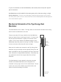
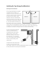
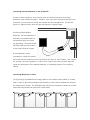
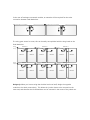
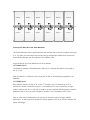
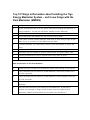
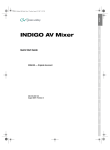
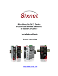
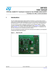
Tigo Energy, Inc. 420 Blossom Hill Road Los Gatos, CA 95032 Tigo Energy Support Note Tigo Energy® Dual Maximizer™ (MM-2ES) – Detailed Design and Installation Guide Tigo Energy Support: 1-888-681-TIGO (8446) [email protected] International Phone: 00800-CALL-TIGO (2255-8446) Before installing or using the Tigo Energy® Maximizer™ System, please read all instructions and warning markings on Tigo Energy products, appropriate sections of the inverter user manual, PV module installation manual, and other available safety guides. Do not remove cover, disassemble, or repair any Tigo Energy equipment. No user serviceable parts. Refer service to qualified personnel only. Installation and service must be performed by trained personnel only. Tigo Energy does not assume liability for loss or damage resulting from improper handling, installation, or misuse of products. Always adhere to all National Electric Code (NEC) ANSI/NFPA 70 and/or local electrical codes. Copyright © 2011 Tigo Energy, Inc Introduction The Tigo Energy® Dual Maximizer™ is the next generation of industry-leading products from Tigo Energy. The Dual Maximizer integrates seamlessly with the rest of the market-proven Tigo Energy Maximizer System. The Dual Maximizer uses the same Impedance Matching™ technology as the Module Maximizer – it simply incorporates two circuits into the same physical component for ease of installation and cost reduction. In this guide, we provide an overview of the new Dual Maximizer System, for installers who are already familiar with the existing Tigo Energy Maximizer System. For those who have not read the Tigo Energy Installation Manual, this guide DOES NOT replace the information in the full Installation Manual. Overview of the Tigo Energy Dual Maximizer The Tigo Energy Dual Maximizer uses the same electrical and communication principles, and many of the same design and installation guidelines of the Module Maximizer. In particular: The PV system is still wired in series, as with the Tigo Energy Maximizer System, so the voltages of the modules always add (rather than current). String sizing is still identical to a system without Tigo Energy: the maximum string length is, as always, determined by the open circuit module voltage at low temperature. No special inverter settings are required. The Dual Maximizer is enclosed in a polycarbonate box, and so does not require any grounding. The rest of the Tigo Energy Maximizer System, including the Gateway, Maximizer Management Unit (MMU), and MaxiManager Software, are all the same, whether they are used with the single-circuit Module Maximizer or the Dual Maximizer. The Dual Maximizer is also designed to be very flexible in how it can be deployed: A Dual Maximizer can be used with just one solar module. So, for example, strings of 11 modules can use 6 Dual Maximizers, and simply connect one of the Dual Maximizer to just one solar module. In this case, please remember to connect the solar module to the “Input A” pair of connections on the Dual Maximizer, and connect (short-circuit) the “Input B” pair of connectors. Dual Maximizers can be installed in the same system, and on the same string, as single Module Maximizers. Since the core technology is identical, these products can be used in the same power system, and can communicate via the same Gateway/Maximizer Management Unit communications system. Mechanical Schematic of the Tigo Energy Dual Maximizer The Dual Maximizer has six cables. The long cables on the ends are the cables for the string, which connect one Maximizer to the next. There are two pairs of PV input cables for the Dual Maximizer, known as “Input Circuit A” and “Input Circuit B”. Circuit A is the left pair when the Maximizer is clipped into the frame of the module. The PV input cables are at different lengths, to help differentiate them and prevent mis-wiring in the field. The Input A wires are shorter, and the Input B wires are longer. Input A: 0.2m, 8 in. Input B: 0.3m, 12 in. When two PV modules are connected to the Tigo Energy Dual Maximizer, they are each kept at their optimal power point, and data is provided for each one (as would be the case if they were each connected to a single Module Maximizer). Electrically, they are combined in series for the output cable from the Dual Maximizer. The Dual Maximizer comes attached to the same mounting bracket as the Module Maximizer, and is designed to be mounted in the top right corner of a PV module frame. The setscrew in the corner of the bracket can provide tension, and allows for electrical bonding to the frame. Series cables: 1.3m, 4 ft. Installing the Tigo Energy Dual Maximizer Mounting the Dual Maximizer A Tigo Energy Dual Maximizer is typically connected to two PV modules. It is mounted to the corner of the frame of one of the two modules, and then connected to the leads from both modules. When Module A Module B viewed from behind, the Dual Maximizer should be connected to the top right corner of the left-side module (known as Module A). The second module connected to the Dual Maximizer will be known as Module B. The two inputs of the Dual Maximizer, known as “Input A” and “Input B” are meant to be connected to their corresponding PV module. Note that the “Input B” cables will be longer, to facilitate the connection to the right junction box, which will be further away. As with the single Module Maximizer, make sure the Dual Maximizer is connected facing the solar module, inside the frame. Press the Dual Input A Input B Maximizer’s bracket into the corner of the module frame. The compression clips on the bracket provide mechanical tension, as well as bonding to the module frame. The ribbed side of the module should be visible, as should the Mac ID label on the bracket. Make sure to mount the Dual Maximizer with the connections facing down – this will prevent water from entering the Dual Maximizer. Module A Connecting the Dual Maximizer to the PV Module In order to avoid connection errors, the two pairs of inbound connectors to the Dual Maximizer come in different lengths. Therefore, even if you don’t have good visibility to the connection, you can avoid mis-wiring the modules into the Dual Maximizer. The left pair (Input A) is slightly shorter, while the right pair (Input B) is slightly longer. As with the Single Module Maximizer, The Dual Maximizer is enclosed in a polycarbonate box, Input A Input B and therefore does not require any grounding. The metal bracket has teeth which provide bonding to the frame of the PV module. A Dual Maximizer can be connected to a single PV module, but in that case the module must be connected to the “Input A” pair of cables. Also, connect the “Input B” connectors together in a short circuit. Failure to do either of these steps will impair the performance of the Module Maximizer, or potentially prevent it from working entirely. Connecting Maximizers in Series Module A The Tigo Energy Dual Maximizer has longer leads on the outbound series cables (1.3 meters each) in order to give system designers the flexibility to mount the Dual Maximizer wherever the system layout dictates. The Dual Maximizer will have the clearance to handle any module layout that was possible with normal PV module leads. In the case of landscape-connected modules, an extender will be required for the series connection between Dual Maximizers. If a string goes around a corner, this can be easily accomplished with the long leads on the Dual Maximizer: String out (-) Maximizer 1 Module A String out (+) Maximizer 2 Module B Maximizer 6 Module A Module A Maximizer 3 Module B Maximizer 5 Module B Module A Module A Module B Maximizer 4 Module B Module A Module B Design tip: When you have a string that doubles back over itself, design the opposite modules to be wired consecutively. This allows the junction boxes to be mounted on the same end, and therefore the Dual Maximizer can be mounted in the center of the paired row. Module B Module B Module B Module B Module B Module B Module A Module A Module A Module A Module A Module A Scanning the Mac IDs of the Dual Maximizer The Dual Maximizers have a special barcode that indicates that it has two modules connected to it. So when you enter them into the Tigo Energy configuration software, the system will automatically populate two PV modules in the software view. A typical Mac ID for a Dual Maximizer will be as follows: 04C05B8A00000001 The bolded 8 indicates a Dual Maximizer, while the “A” indicates the Module connected to the “A” circuit. After that Mac ID is scanned in, the second Mac ID will be automatically populated in the database: 04C05B8B00000001 Note that this mac ID still has an “8” as the 7th character, but it is followed by a “B” to indicate the module connected to Input B. If the Maximizer is only connected to a single module, make a note of it in the pop-up window, and the software will disregard the second Maximizer Mac ID, and just show a single PV module in the visualization of the circuit. Keep in mind that Dual Maximizers can be used in the same system as Single Module Maximizers. In that case, enter all Mac IDs as they appear in the circuit, and the software will adjust accordingly. Activating the Tigo Energy Dual Maximizer System Turn-on voltage The Tigo Energy Dual Maximizer features a new safe turn-on voltage, which enables an installer to install the system, verify the string sizes, and test polarity, all with safe voltage levels. Each PV module will create 5 volts on the series circuit (so, for example, a string of 12 modules would have a total string voltage of 60V). The polarity of the voltage will be the same as the true polarity of the PV modules, so you can also verify the polarity of the strings in a low-voltage environment. Discovery and Power On In order to turn on the system, simply run the “Discovery” process from the MMU. This will take approximately 15 minutes per Gateway in the system. As soon as each Maximizer is discovered, it will activate to full power, and the voltage from each Dual Maximizer will be as high as the sum of the open circuit voltages of the PV modules connected to it. Please note that the inverter cannot be turned on before the “Discovery and Power On” sequence is run. Top 10 Things to Remember about Installing the Tigo Energy Maximizer System – and 5 new things with the Dual Maximizer (MM2ES) 10 Configure the system online before installing on-site. 9 Record the Maximizer Mac ID on the system map before installing the Maximizer, or during installation. Use the peel-off stickers available on each Maximizer. 8 Install the Gateway in the center of the array. 7 Mount Maximizers and Gateway with the connectors facing down. 6 If the system includes multiple Gateways, install them in series along a single RS-485 cable run (up to a maximum of 360 Maximizers per MMU. 5 If multiple Gateways, use a termination resistor on the final Gateway in the RS-485 string. 4 Do not exceed 50 ft. radius between a Gateway and its corresponding Maximizers. 3 Maximizers must be installed on each PV module within an inverter’s MPPT zone. 2 Connect the Maximizers to the PV module before wiring them in series. 1 Initiate “Discover and Power On” before connecting strings in parallel. New Requirements of the Dual Maximizer 5 Initiate Discovery & Power On to activate the system before turning on the inverter. 4 If only connecting one PV module to a Dual Maximizer, connect the module to the Circuit A connectors. 3 If only connecting one PV module to a Dual Maximizer, connect together (short) the Circuit B connectors. 2 With landscape modules, mount consecutive junction boxes in pairs, near a Dual Maximizer. 1 Take care when determining the quantity of Dual Maximizers. In particular, if modules are connected in strings of odd numbers, then the number of Dual Maximizers CANNOT be determined by the module count divided by 2.