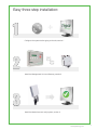
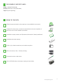
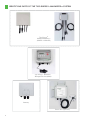
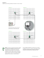
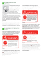
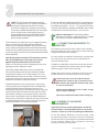
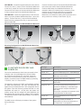
1
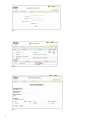
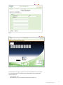
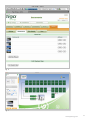
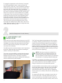
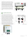
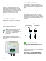
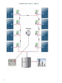
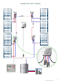
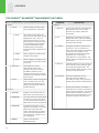
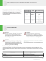
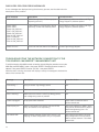
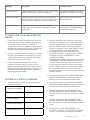
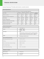
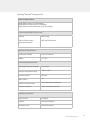
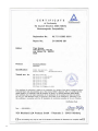
INSTALLATION AND SAFETY MANUAL
For Tigo Energy Module Maximizer (MM-ES) and (MM-2ES)
®
TM
Manual version 2.2 Dated 02/20/2012
Applies to the following:
All Tigo Energy Module Maximizers series (MM-ES)
Tigo Energy® Maximizer™ Management Unit (MMU)
Tigo Energy® Gateway (GTWY)
TABLE OF CONTENTS:
Safety Instructions..………...………………………………………...............................4
Identifying Parts of the Module Maximizer System…………....................................6
Configure the System Before Going to the Site........................................................7
Install the Management Unit and Gateway...............................................................12
Install the Maximizers and Verify System.................................................................17
Troubleshooting........….............................................................................................25
Warranty Information………......................................................................................29
Technical Specifications............................................................................................32
This is manual version 2.2 Dated 02/20/2012
Please check: https://datacenter.tigoenergy.com/main/installations.php to make
sure you have the most up-to-date version.
PRODUCT SYMBOLS
Failure to follow instructions may result in serious hardware failure, injury, or death.
Use extreme caution when performing this task.
Low Voltage Directive 2006/95/EEC
UL 1741 Safety Standards for Distributed Generation
2
Easy three step installation:
1
Configure the system before going to the site, section 1
2
Install the Management Unit and Gateway, section 2
3
Install the Maximizers and verify system, section 3
www.tigoenergy.com
3
PLEASE READ THIS FIRST:
IMPORTANT SAFETY INSTRUCTIONS
SAVE THESE INSTRUCTIONS
This manual contains important instructions for installation and maintenance of
the Tigo Energy® product models MM-ES050V300W, MM-ES075V350W, MMES110V300W, MM-ES170V300W, MM-2ES050V300W, MU-ESW, and related
Tigo Energy software applications.
Risk of electric shock, do not remove cover, disassamble, or repair. No user
serviceable parts inside. Refer servicing to qualified service personnel. See
warranty in the appendix for instructions on how to obtain service.
Before installing or using the Tigo Energy® Maximizer™ System, please read all
instructions and warning markings on the Tigo Energy products, appropriate
sections of your inverter manual, photovoltaic (PV) module installation manual,
and other available safety guides.
Failure to adhere to these instructions may result in injury or death, damage to
the system, and voiding the factory warranty.
To reduce risk of fire and shock hazard, install this device with strict adherence
to National Electric Code (NEC) ANSI/NFPA 70 and/or local electrical codes.
When the photovoltaic array is exposed to light, it supplies a DC voltage to the
Tigo Energy® Module Maximizer™. The Module Maximizer starts in the “on” state
and its output voltage may be as high as the PV module open circuit voltage (Voc)
when connected to the module. The installer should use the same caution when
handling electrical cables from a PV module with or without the Tigo Energy
Module Maximizer attached.
Installation must be performed by trained professionals only. Tigo Energy
does not assume liability for loss or damage resulting from improper handling,
installation, or misuse of products.
Remove all metallic jewelry prior to installing the Tigo Energy Module Maximizer
to reduce the risk of contacting live circuitry. Do not attempt to install in inclement
weather.
Do not operate the Tigo Energy Module Maximizer if it has been physically
damaged. Check existing cables and connectors, ensuring they are in good
condition and appropriate in rating. Do not operate the Tigo Energy Module
Maximizers with damaged or substandard wiring or connectors. Tigo Energy
Module Maximizer should be mounted 3 ft. minimum above ground.
Do not connect or disconnect under load. Turning off the Inverter and/or the Tigo
Energy products may not reduce this risk. Internal capacitors within the inverter
can remain charged for several minutes after disconnecting all power sources.
Verify capacitors have discharged by measuring voltage across inverter terminals
prior to disconnecting wiring if service is required.
Service Personnel: Check the voltage of the array after activating the Tigo
Energy® PV-Safe™ function on the MMU prior to performing service.
Always assume Maximizer is in on state, or may turn on when restarting.
4
Tigo Energy support lines:
(USA) +1.888.609.TIGO (8446)
(Europe) +800-CALL-TIGO (2255-8446)
skype: support.tigoenergy
BRING TO THE SITE:
Ethernet equipment (cable or other options to connect MMU to local router)
A laptop PC, smart phone, or internet connected device to track completion of
each step in the on site installation procedures.
Installation company master user ID/password information if already established.
Installation schematic drawing.
Phillips (#1), slotted screwdrivers, and needle nose pliers.
MC4 connectors (1 male, 1 female per string)
Permanent marker or label maker.
Spool of RS-485 cable, wire stripper, cripping tool and others.
www.tigoenergy.com
5
IDENTIFYING PARTS OF THE TIGO ENERGY ® MAXIMIZERTM SYSTEM
Tigo Energy®
Module MaximizerTM
(MM-ES or MM-2ES)
Tigo Energy® MaximizerTM
Management Unit (MMU)
Gateway
Sensor Box (Optional)
6
1
Configure the System Before Going to the Site
1.1 System Configuration
To ensure full functionality of the software installation
tools (ex. the “Status Page”), the installer must complete
this step prior to installing any of the Tigo Maximizer
System hardware.
For a first-time installation create a user name
and password by going to www.tigoenergy.com
and selecting “login“ in the upper-right hand corner. From
the next page, click on the link that says “New Installer?
Sign up.” A new page will appear where a new Tigo
Energy Account can be created. Enter all asterisk fields
with the appropriate information.
1.1.1 Create a New User Name
Fill in all the fields, and press “Submit” to confirm. An
e-mail will be sent to the e-mail address that was entered
on the previous page.
Login to e-mail account provided, select the e-mail from
Tigo Energy, and click on the link provided in the e-mail
to activate the Tigo Energy account. The link will return to
the Tigo Energy login page, use the new user name and
password to enter the site.
NOTE: The user name and password will become
the Installation Company’s master login information
that will be used for setting up and configuring all
future sites.
Upon entering the “My Installations” page, press the
“New Installation” button to create a new site. A 2-step form
will request all necessary information about the site. (Fig. 1)
1.1.2 Enter the System
Configuration
Have the 12 digit code from the Management Unit, and
all of the Mac IDs from the Maximizers available before
starting the system configuration process. Maximizer
codes can be found on the outside of the box; this is not
recommended if box has been opened. All identification
codes are located under the barcode of the unit and can
be entered manually or with a barcode scanner.
Enter the Site Name, Installation ID (which can be any
number, or can be left blank and will be auto-assigned by
Tigo), and 12-digit MMU identification code in the blank
fields on this page. Press “Next” to save and continue. (Fig. 1)
Fill out all sections with blank fields:
• Installer Information
• Project Site Information
• System Information
• Press “Finish” to save all information.
A new page will appear stating that the form was finished
and saved. Click on “Go to My Installations Page” to
configure the new site. On the “My Installations” page,
scroll to “pending sites“ and press the “Configure” button
next to the new site. This will begin the 3-part System
Configuration process for the new site. (Fig. 2)
All fields in this section should be auto-populated with
information from the “New Site” form. If this is a multigateway system, ensure that the field marked “Number of
Gateways” displays the correct number of Gateways that
are in the system. Once all information has been verified,
press “Next” to save and continue. (Fig. 3)
Enter ID codes for all of the Maximizers in the system.
This is best done with a handheld barcode scanner. Keep
in mind that if a Dual Maximizer (MM-2ES) is scanned, it
will populate two slots in the string, to represent the two
modules that will be connected to it.
After entering a Maximizer’s ID, make sure to label the unit
with the specific designation it was just assigned using a
permanent marker (i.e. A1, A2… B1, B2…etc). (Fig. 4)
After saving, a new page will appear. Click “My
Installations” to access the newly configured site. Once
on the “My Installations” page, select the site by clicking
on the site name (Fig. 5).
www.tigoenergy.com
7
Fig. 1
Fig. 2
Fig. 3
8
Fig. 4
Fig. 5
The modules will be “gray” at this time until each Maximizer is connected
to its corresponding PV module and the Management Unit establishes
communication to:
1) the internet, and
2) the Maximizers via the Wireless Gateway (see Step 3.1).
www.tigoenergy.com
9
1.2 Setting up the “System Owner”
Password and Permissions
Log on to https://datacenter.tigoenergy.com/main/
installations.php. Enter the installer’s login information
and select the corresponding installation site name.
Select the “Admin” tab from the MaxiManager feature
menu. Select the “Users” tab on the lower menu bar.
Click the “Add New User” button on the bottom left of the
window. A new pop-up screen will appear.
the installer to select which screens and features will
be available to the system owner. “Update” access
provides full visibility with editing capabilities; “Browse”
access provides read-only visibility; “None” removes the
entire tab or feature from view when logging on as the
system owner. Press the “submit” button to complete the
addition, or close the screen without saving by clicking
the “X” at the bottom right of the pop-up screen.
NOTE: only one account for a system owner may
be created per license.
1.3 Verify System Information
Once the configuration process is completed,
enter the new site and select the ‘Admin’ tab to
verify that all of the information is correct on the ‘Setting’
and ‘Site Details’ sub-tabs (Fig. 6).
Most of the information in these sections will have been
auto-populated during the System Configuration process.
Please verify that all of the information entered is correct,
and fill in any missing fields if found.
1.4 Entering Photos and
Changing the Appearance of
the Summary Page (optional)
While still in the “Admin” tab of the MaxiManager
application, select the “Appearance” tab.
In the space provided, enter the Login Name and
Password (re-enter the password in the second
box) which will be used as the system owner’s log in
credentials. Record this information inside the front
cover of the “System Owner’s Manual”. Enter the system
owner’s first name, last name and e-mail address in the
space provided.
Select the user profile (e.g. System Owner) from the
“User Type:” drop down menu. This will configure
the new user’s access rights to the default values as
recommended by Tigo Energy. Default settings provide
the system owner access to the screens that will be
useful without overloading them with data. To modify
these access rights (provide more or less feature access)
click on the “Show Advanced Options” link. The radio
buttons that appear in the lower half of the screen allow
10
Add pictures of the site by clicking the “Add New Picture”
button. A pop-up screen will appear. Press “Choose
File” to select a photo file from your computer directory.
Press “Add a New Picture” button once the file has been
selected to confirm the addition, or click the “X” in the
lower right corner of the pop-up to exit without posting a
photo. Repeat for additional photos. (Fig. 6)
Fig. 6
Fig. 7
www.tigoenergy.com
11
To change the appearance of the “Summary” tab press
the “Edit System Map” button. A pop-up screen will
appear with the “Edit Tool,” which enables the installer to
modify the appearance and placement of modules when
they are on the “Summary Page” (Fig. 7). Modify the
layout of the array by clicking and dragging modules with
the cursor. To snap the modules to a grid, click the grid
button in the upper left. Lines and labels can be added
to the system map under the tools category. Clicking on
anything in the picture will pull up the properties menu.
In this menu modules can be moved and arranged in
landscape orientation. A picture can be uploaded to the
background of the site if the system owner chooses.
This can be done under the background menu. Once
all changes and additions have been made, click on the
“Save” button to confirm. To view the changes that were
made, select the “Summary” tab.
2
Install the Management Unit and Gateway
2.1 Management Unit
Installation
Ensure the AC and DC disconnect switches are in the OFF
position for the inverter. Mount the Maximizer Management
Unit (MMU) in a location that has access to an AC power
source, a stable network connection, and proper cable
connection to the Gateway.
The MMU should be mounted between 3 and 5 feet above
the ground. Mounting tabs are provided for installing on
unistrut or directly to a wall surface.
The power cord for the MMU is provided with the system
kit and is connected to the terminal within the Maximizer
Management Unit enclosure. For safety compliance,
outdoor installations also require weatherproof housing be
used to enclose the AC power adapter.
The Tigo Energy Maximizer Management Unit includes
an external, weather-proof Ethernet port on the bottom
surface. Connect an Ethernet cable (not provided) to a
live port and then to the MMU. For outdoor installations,
install a weatherproof cap (provided as an option) to the
Ethernet port by threading the Ethernet cable through the
cap, plugging in the Ethernet cable, screwing on the cap
to the port, and hand tightening.
NOTE: If the array is going to be placed on a
multi-roof surface, or contains more than 120
modules total, then this system requires more
than one Gateway. Please contact your distributor
for information on ordering additional Gateways.
The MMU is connected to the Gateway using an RS-485
cable. The cable should be a four-conductor, twisted
pair, outdoor-rated wire of at least 18AWG. See Tigo
Energy’s website for a list of tested cable options.
Access the MMU communications ports by pressing the
latch at the bottom edge of the clear cover of the MMU
and opening the enclosure. Remove the lower cover
panel (which has the Tigo Energy logo) by unfastening
the two screws in the bottom corners with a Phillips head
screwdriver.
To install the RS-485 cable, completely remove the nut
from the cable gland. Feed the cable through the nut,
and the cable gland into the MMU housing. Attach the
four wires to the cable connector terminal, which can be
12
Management Unit Connection
Drawing
removed from the circuit board for easier handling. Reengage the connector into the RS-485 port on the right
side. Take special care NOT to insert this in the Auxiliary
RS-485 port. Note the wire colors used on the MMU
connection so you can connect the other end of the
wire to the Gateway with the same color configuration.
Replace the nut on the cable gland and hand tighten. If
four-conductor twisted pair cable is not available, then
outdoor-rated Cat 5 Ethernet cable can be used instead.
See Appendix B for instructions on installing Cat 5 cable.
Replace the lower cover panel, and securely fasten the
two screws in the bottom corners with a Phillips head
screwdriver. Close and latch the protective cover in the
MMU.
2.2 Gateway Installation
Series Wiring Example
A Gateway is provided with the system kit to create
the communications link to the Tigo
Energy Module
Make sure that wiring matches
the terminal in the MMU.
Maximizers. Install the Gateway onto the module frame in
the top left corner by pushing the compression clips on
the bracket onto the module metal frame and thightening
B A in lbs. to ensure
B A
the set-screw at a torque rating of 15-20
bonding. The face of the Gateway (including the removable
face and the label) should be facing out of the module
frame. Confirm that the connectors are facing down.
To connect the RS-485 cable to the Gateway, start by
opening the cover of the Gateway. Keep the cover in a
clean, safe place to prevent dirt from getting on the seal.
Insert the RS-485 cable through the left gland on the
bottom of the Gateway. Tighten the cable wires into the
bulkhead connector using a small screwdriver. Remove the
connector from the circuit board for easier handling (Fig. 8).
Status:
Legend
Tigo Energy
PV-SAFE
24V (-)
24V (+)
Tigo B
Tigo A
Power
Connector
Power
Adaptor
Ethernet
Jack
Gateway
Cable
Termination Example
Make sure that wiring
matches the terminal
in the MMU.
B A
Termination resistor:
place termination
resistor between A
and B of last Gateway.
B A
Termination Resistor
Old Sensor Wiring Diag
Blink
Normal Operation
Power, No Comm.
No Power
Fig. 8
www.tigoenergy.com
13
Make sure that the wire connected to each terminal
in the Gateway matches the connections in the
Management Unit.
If the system has multiple gateways, use the second
connection for the outbound cable to the second
gateway. Remove the termination resistor (the small
electrical component) from the right four-pin connector
in order to wire the outbound RS-485 cable to the next
Gateway. Only the final Gateway in the series
connection should have a termination resistor.
When finished, replace the cover of the Gateway. Handtighten screws only.
2.2.1 Gateway Location
The ideal location for the Gateway is underneath one
of the central panels in the array so that the distance
from any corner panel to the Gateway is the same. The
Gateway comes pre-mounted on a bracket which can
be attached to a module frame with the included clips.
When attaching to a module place in the upper left
hand corner with antenna pointing downward. Exact
location can be optimized in Section 3.4.
2.2.2 Multiple Gateways
In larger (those over 120 modules) or multi-surface PV
projects, more than on Gateway will be required to support
proper communications between the Maximizers and the
MMU.
To plan the number of Gateways required for the design,
partition the system into clustered blocks (up to 120
modules) or separate sub-arrays. The Module Maximizers
in any block should not be more than 50 feet from the
Gateway.
Place a Gateway in the physical center of each block
or sub-array and connect the Gateways in series, using
the second four-pin connector as the outbound cable from
one Gateway to the next. Repeat this process until the final
Gateway is
installed.
Keep in mind that only the final Gateway in the series
connection should have a termination resistor.
Series Wiring Example
Make sure that wiring matches
the terminal in the MMU.
NOTE: The Gateway should NOT be located
where it may encounter direct exposure to
sunlight or rain-fall, or be placed where the unit
could be sitting in pooled water for long
periods of time.
B A
Outbound connection to next Gateway.
B A
Position the Gateway at the center of the module
cluster and attach to the upper left-hand corner of a PV
module frame.
2.3 Power On the MMU
IF A SENSOR BOX HAS BEEN ORDERED WITH THE
SYSTEM DO NOT PROCEED BEFORE READING
SECTION 2.4
Plug the MMU power cord into an AC outlet and ensure
the MMU has access to the internet. Connect the MMU
AC power circuit (do not use a separate
Status:to the site’s main Blink
or dedicated power supply).
Normal Operation
DO NOT INITIATE “DISCOVERY AND POWER ON”
Power,UNTIL
No Comm.
ALL MAXIMIZERS HAVE BEEN INSTALLED.
No Power
14
Term
Make
match
in the
Diagram A:
System layout showing Gateway mounted in center of arrays
Sub Array 1
Sub Array 2
Gateway
Gateway
MMU
Position the Gateway at the center of the
module cluster and attach to the upper
left-hand corner of a PV module frame.
Sub Array 3
Sub Array 4
Terminated
Gateway
NOTE: To verify if a connection has been made to
the network, the installer can perform a network
test directly from the MMU (see networking
troubleshooting in appendix C). If a laptop is
available, select the ‘Status’ page to see when
the MMU was last updated. If the ‘Last Updated’
section appears in red, then the MMU has NOT
established connection to a viable network.
Gateway
Once the MMU establishes connection to a network,
the MMU will power up, perform configuration checks,
download the latest system software if updates are
available, and download the configuration data.
www.tigoenergy.com
15
2.4 Sensor Installation
(optional)
If additional sensors are required
for the project for measuring light
intensity, back-panel temperature,
string current or voltage, these
accessories may be ordered with
the Tigo Energy® Maximizer™
System at the time of purchase.
The Tigo Energy sensor
accessories are powered RS-485 devices and are
connected through the same RS-485 cable that connects
the Gateway.
Install pyranometer, thermocouple(s) or current/voltage
sensors within the array as desired. Place the Tigo Energy
Sensor Box in close proximity to the sensor(s) within
the array. The Sensor Box is provided with a module
frame mounting bracket if frame mounting is desired and
appropriate.
The sensor boxes are connected in series,
identical to that of a multi-gateway system (see “MultiGateway Systems” for information on how to connect
sensor boxes to the RS-485 chain). Be sure to install
them before the final (terminated) Gateway in the circuit.
2.5 Placement of the Caution
Labels
Place these labels in a visible location on the front
surface of the DC disconnect unit (typically found next
to or integrated into the inverter) and on the front surface
of the fuse combiner box (typically found adjacent to the
array in multi-string projects).
WARNING
Tigo Energy
PV-SAFE
Tigo Energy PV-SAFE®
TM
For use by service
personnel only
Tigo Energy
PV-SAFE
Tigo Energy PV-SAFE®
TM
For use by service
personnel only
Press Tigo Energy PV-Safe button
on the Management Unit before
energizing this DC disconnect.
Once turned ON, reactivate the
modules from the Management
Unit console.
DC disconnect
Figure 1
DC disconnect and fuse combiner box labels - contains
the Tigo Energy PV-Safe logo and states (Figure 1)
WARNING Press Tigo Energy PV-Safe button on the
“
Management Unit before energizing this DC disconnect.
Once turned ON, reactivate the modules from the
Management Unit console.”
16
energizing this DC breaker or fuse.
Once turned ON, reactivate the
modules from the Management
Unit console.
DC breaker
Figure 2
DC disconnect and fuse combiner box labels - contains
the Tigo Energy PV-Safe logo and states (Figure 2)
WARNING Press Tigo Energy PV-Safe button on
“
the Management Unit before energizing this DC breaker
or fuse. Once turned ON, reactivate the modules from
the Management Unit console.”
Included with the system documentation are three
labels which are essential to indicate that the PV system
contains the Tigo Energy® MaximizerTM system with the
PV-SafeTM feature and proper precautions are taken
during the operation of the project.
WARNING
Press Tigo Energy PV-Safe button
on the Management Unit before
Tigo Energy
PV-SAFE
Tigo Energy PV-SAFE®
TM
For use by service
personnel only
This PV system is equipped with the
Tigo Energy® MaximizerTM solution.
To de-energize the DC wiring,
activate the PV-Safe feature at
the Tigo Energy® MaximizerTM
Management Unit prior to opening
the AC breaker.
AC breaker
Figure 3
AC Disconnect Label-contains the Tigo Energy PV-Safe
WARNING This PV system
logo and states (Figure 3) “
is equipped with the Tigo Energy® MaximizerTM solution.
To de-energize the DC wiring, activate the PV-Safe
feature at the MMU prior to opening the AC breaker.”
Place this label in a visible location on the front surface of
the AC Disconnect (typically found adjacent to the main
circuit breaker panel).
3
Install the Maximizers and Verify System
NOTE: The Tigo Energy Module Maximizers are
factory configured in the “on” position and therefore
may produce voltage as high as the PV module
open circuit voltage (Voc). If there are two modules
connected to a Maximizer MM-2ES, then the voltage
can be as high as twice the module’s maximum
power voltage. Please read “IMPORTANT SAFETY
INSTRUCTIONS” at the beginning of this manual
before starting installation.
Confirm that the PV module open circuit voltage (Voc) rating
does not exceed the Tigo Energy Module Maximizer’s
maximum input voltage specification. Also, confirm that the
Vmp is within the range specified for the Module Maximizer.
Confirm the PV module’s maximum short circuit current (isc)
is within the rated current limit for the Module Maximizer (MMES and MM-2ES).
Note: During series connection of PV modules in reverse
bias, the last Maximizer of the string may carry the
highest absolute backfeed short circuit current.
Refer to the Tigo Energy module configuration tool at: www.
tigoenergy.com/our_products for help.
Tigo Energy Module Maximizers are to be installed with
the connectors facing downward and should be installed
underneath the module, out of direct sunlight or rain. The
Module Maximizers are to be mounted a minimum of three
(3) feet above the ground. Failure to adhere to the installation
instructions will result in voiding the warranty.
Install the Maximizer on the module frame in the top right
corner by pushing the compression clips on the Maximizer
bracket (included) onto the metal frame structure. The
compression clips feature small barbs at the ends of the clips,
which provide tension and bond the bracket to the module
frame. When installing on a frame-less module or when the
frame corner is inaccessible, mount the Module Maximizer
directly to the rack structure. Holes are provided in the bracket
to enable attachment to the mounting structure. Be sure to
follow the guidelines in the previous paragraph.
Continue installing the Module Maximizers in sequential order
(i.e. A1, A2, A3…etc) until the first string is complete. Repeat
for additional strings (B1 ... Bn; C1 ... Cn; etc.) until PV array is
complete. Note that when installing an MM-2ES, the numbers
will sequence in increments of two (i.e. A1, A3, A5, etc.).
A Note on Grounding: The Tigo Energy Module
Maximizer is enclosed in a polycarbonate (non-metallic)
box that does not require additional grounding.
3.1 Connecting Maximizers to
Modules
The installer should use the same caution when handling
electrical cables from a PV module with or without the Tigo
Energy Module Maximizer attached.
For each module connected to a Maximizer, plug the leads
from the junction box into the input connectors (short
wires) on the Maximizer.
If installing an MM-2ES, connect the second pair of short
wires on the Maxmimizer. Note that the pairs are slightly
different lengths to help avoid mis-wiring.
If there are an odd number of modules on the string, then
an MM-2ES can be connected to just one PV module.
In that case, be sure to first short (connect
together) the “Input B” pair of connectors, and
then connect the single PV module to the “Input
A” pair of connectors.
Always assume Maximizer is in on state, or may
turn on when restarting.
You must complete this step before moving on.
3.2 Wiring to Adjacent
Maximizers
Important: You must connect Maximizers to their PV
modules before connecting Maximizers to each other
in series. Failure to do this may damage the Maximizer.
On the first Module Maximizer of the first string, locate
the positive lead (has a red sleeve next to the connector).
Connect the red (+) output lead from the Module Maximizer
to the extension cabling which connects to the string
combiner or directly to the inverter.
www.tigoenergy.com
17
FOR MM-ES: Locate the negative lead (has a blue sleeve).
Connect the blue (-) output of the first Module Maximizer
to the red (+) output wire of the second Module Maximizer.
Connect the blue output of the second Module Maximizer
to the red output lead of the third Module Maximizer.
FOR MM-2ES: Locate the negative lead (on the left most
side of a properly installed Module Maximizer – has a blue
sleeve). Connect the blue (-) output of the first Module
Maximizer dual package to the red (+) output wire of the
adjacent MM-2ES.
Connect the blue output of the second Module Maximizer
to the red output lead of the third Module Maximizer.
Continue these steps for all Module Maximizers. An
extension cable (not included) may be necessary if two
modules are not physically adjacent to one another.
Connect the blue (-) output wire of the last Module
Maximizer to the extension cabling which connects to the
string combiner or directly to the inverter. (Fig. 9).
Mounting Configuration for MM-2ES Module Maximizer
Mounting Configuration for MM-ES Module Maximizer
Fig. 9
3.3 Initiate Discovery and
Power On
Once all of the Maximizers have been connected to their
modules, return to the Management Unit and initiate
the “Discovery and Power On” command, which will
also power on the Maximizers (if they not powered on
already). Access this from the MMU display by selecting
“2 Control”, then “2.1 Discover/Pwr”.
The discovery process will initiate communication between
the MMU and Maximizers, and verify the Maximizer IDs
against the list of Maximizer IDs in the configuration file for
the system. Once the discovery process has been run, the
Maximizers will power on. At this point, the system can
produce power, and the voltage from each Maximizer can
be as high as the maximum power voltage of its PV module.
The discovery process will take approximately 15 minutes for
each Gateway.
The MMU screen will display the status of the system
during discovery:
18
Message
Description
“Find Gateways…”
Searching for Gateways
“Found: X/Y”
Found X Gateways out of Y total Gateways
“Gateways: OK”
Correct number of Gateways found, and all
Gateways are functional
“Channel Check…” Verifying radio channel for Gateways
“Assign X/Y”
Assigning Maximizer X out of Y total
Maximizers
“Step[X/Y]: P%”
Each step corresponds to the discovery
process of a Gateway (Y total Gateways),
with the percent complete indicated of
each step.
The percent completed will reset each time
a new Maximizer is discovered
“Found X/Y”
Found X Maximizers out of Y total; still
processing
“Done X/Y”
Discovery process is finished. X
Maximizers were found and assigned out
of Y Maximizer in configuration
If any error codes come up during the discovery process,
see the list of discovery error codes in Appendix C. When
finished, the MMU screen will indicate that all Maximizers
have been successfully discovered and assigned (e.g.:
“Done: 36/36”).
If an internet connection is available on-site,
go to the Status Page once all Maximizers
are connected to the panels to ensure they
are all connected properly, registering
voltage, and receiving a sufficient RSSI.
If installing a multi-string system, you must initiate
Discovery and Power On before connecting strings in
parallel.
3.4 Verify Gateway Signal
Locate the MMU display to aid in placement of the
Gateway. If the Gateway is placed in a location that is
not ideal for stable communication with the Tigo Energy
Maximizers, two messages will appear on the MMU
display.
The first will say “Panel Not Comm.” and will provide
a count of how many Maximizers out of the total in the
array are not communicating with the Gateway (e.g. Panel
Not Comm. 3/14). The second will say “Panel Signal
Low” and will provide a count of how many Maximizers
out of the total that are already communicating with the
Gateway that have weak signal strength, and thus are
unable to communicate effectively with the Gateway. By
paying close attention to these warning messages, the
installer can locate the most ideal place for the Gateway
to be able to communicate effectively with all of the
Maximizers in the array.
Proactively validate the signal strength by lifting the
protective cover on the MMU and selecting the “MENU”
button. Select “1. STATUS”, and then “1.1. PANELS”.
Finally, select “1.1.1. SIGNAL”. This part of the MMU
menu will display all of the configured panels in a list
with signal strength marked next to each panel. Use the
up and down arrows to scroll through the list. Pressing
“ENTER” will allow you to take a new reading of the PV
array’s signal strength.
NOTE: For troubleshooting purposes, the weakest panels are sorted to appear first in the list.
You must successfully complete this step before moving on to the rest of the installation process.
www.tigoenergy.com
19
Connector Layout - MM-ES
20
Connector Layout - MM-2ES
A3
A6
Gateway
A4
A5
A1
A7
A2
www.tigoenergy.com
21
3.5 Test String Polarity, Tigo Energy® PVSafeTM Function and Power
3.5.1 String Voltage Polarity
Check
As with any installation of a PV system, the installer
needs to verify polarity and voltage of each string before
connecting them in parallel with one another. This is still
the case with a Tigo Energy system.
The MMU display can help confirm voltage readings for
each of the panels in each string. Lift protective cover
on the MMU and select “MENU”. Select “1. STATUS”,
then select “1.1. PANELS”. Scroll down and select
“1.1.2. VOLTAGE”. The display will show a list of all the
configured panels in the PV array with voltages marked
next to each panel. Pressing “ENTER” will refresh the
screen and provide the most current voltage readings
for all of the panels. Make a note of any string that has
reverse polarity and/or any string that may not have full
Voc voltage at this time to address after the testing the
PV-Safe function next.
3.5.2 Test PV-Safe Function
Depress the latch to open the clear
protective cover on the MMU and
press the button labeled “Tigo
Energy PV-Safe” on the Tigo Energy
Maximizer Management Unit.
When the PV-Safe button is activated, the MMU will
display “PV-SAFE PRESSED” and “Requesting ...” to
indicate the command has been sent to the Maximizers.
As the Maximizers are responding, the MMU display will
indicate how many have successfully disconnected (e.g.
“Resp: 15/48”).
Once the system successfully receives acknowledgement
from all of the Module Maximizers in the array, the MMU
will display “RESPONDING”.
Should the MMU not receive proper response from one
or more of the Module Maximizers or communication has
been lost, the display will read “NOT RESPONDING”.
If this message is present, the owner or installer must
assume that the system is still active and voltage
is present as in a standard PV array. Refer to the
Troubleshooting section for instructions on verifying the
system communication is operating properly.
Please ensure safety precautions are always observed
to avoid contact with solar wiring regardless of the
state of PV-Safe. Tigo Energy cannot guarantee that
modules are fully deactivated. The Maximizers may
still be energized. The Tigo Energy PV-Safe feature is
not a mechanical disconnect.
Please note that in the case that the PV-Safe feature is
triggered automatically (by disconnecting the AC breaker
or from a prolonged grid outage), the Maximizers will
immediate shut off for safety. However, the following
morning (after the Maximizers reset), they will power on
and there will be voltage present on the lines, even if the
inverter and MMU are inactive.
NOTE: This step should be performed at the
installation and annually thereafter to ensure that
the PV-Safe function is in good working order.
These same steps can be used when activating the
feature for system maintenance or emergency
services.
22
3.5.3 Correct any Identified
Issue
At this time, if any strings have reverse polarity proceed
with corrective rewiring of the strings and go back and
redo this step to verify that the issue has been corrected.
If the voltage is not as high as expected, this may be an
indication that one or more of the Maximizers in the string
is not working properly.
This can also be verified from the Summary tab on the
MaxiManager web-interface. Grey panels indicate no
communication. If this is the case go back to Step 3.4.1
to relocate the Gateway for better communication with all
Maximizers in the array. Proceed to the next step when all
Maximizers are communicating with the MMU.
3.5.4 Power Production Check
The MMU display can be used to verify power
production for each panel in the PV array. Lift
protective cover on the MMU and select “MENU”.
Select “1. STATUS”, and then “1.1. PANELS”. Scroll
down to select “1.1.3. POWER”. The display will show
a list of all the configured panels in the PV array with
wattage values marked next to each panel. Pressing
“ENTER” will refresh the screen and display the most
current power output readings for all of the panels in
the array.
Since PV-Safe has been activated, you must now activate
the panels: First Lift the protective cover on the MMU and
select the “MENU”. Scroll down to select “2. CONTROL”.
Scroll down to select “2.1. PANELS ON”. Press “ENTER”
again to confirm.
www.tigoenergy.com
23
A
Appendix
Tigo Energy ® Maximizer TM Management Unit Menu
COMMAND
DESCRIPTION
1. Status
DESCRIPTION
3. Network
1. Panels
1. Signal
Real-time status of each of the
connected panels in the system.
All configured solar panels are
shown in a list, with signal strength
displayed for each. User can
press Up/Down arrows to scroll
through the list; and Enter to take
a new reading of signal strength.
For quick identification during
troubleshooting, the weakest
panels are sorted to appear first in
the list.
1. Display IP
Shows the IP address of the Maximizer
Management Unit, on the premise
network. Very useful to determine
connectivity.
2. Test
Validates the connection to the Tigo
Energy data center, without transferring
data. Displays “Success” if the Internet
connection is functional.
3. Configure
Configures the MMU’s wired Internet
connection. This is a sequence of
steps, where the operator will be asked
a series of yes/no questions, and
also asked to enter data if necessary.
Indicating “Yes”, when asked
“Automatic IP?”, will use DHCP - the
easiest and best configuration for most
connections.
2. Voltage
Same as Signal, but displays DC
voltage of each panel.
3. Power
Same as Signal, but displays how
many watts of power each panel is
producing.
4. Set Proxy
2. Date/Time
Clock read-out. Time is
automatically set from the
Internet connection, each time
the MMU is rebooted. If the
Internet connection has yet to be
established, time display will likely
be inaccurate.
Configures the use of a proxy server for
HTTP requests when transferring data
to the Tigo Energy data center. Not
recommended, unless necessary to get
through a corporate firewall.
5. Set Default
Shows the ID of each management
unit, a 12-letter code. This will
also be the MAC address of the
Ethernet port (useful for network
troubleshooting).
Sets the management unit to a
temporary static IP address of
192.168.0.15. Rarely useful, except for
testing during network troubleshooting.
6. Renew
Resets the IP address of the MMU. If
“Automatic IP” is chosen, uses DHCP to
request another IP address. This should
be done after making any changes to
the premise router configuration, or any
changes to the Ethernet connection.
3. Unit ID
2. Control
24
COMMAND
1. Discovery
Initiates communication with all
Maximizers, and powers them on.
2. Panels ON
Connects power to all solar panels.
Use this to turn the system back
on, after having earlier hit the “PVSafe” button to turn the system off.
3. Push Data
Immediately attempts to make
another communication to transfer
data to the Tigo Energy data
center, without having to wait the
usual 10 minute period between
communications. Useful for realtime debugging.
4. Restart
Reboots the Maximizer
Management Unit.
B
Installing Cat 5 Cable between the MMU and Gateway
If four-conductor twisted-pair cable is not available, then
the MMU-Gateway connection can be wired with Cat 5
Ethernet wire. The data feed (leads A and B on the MMU
and Gateway terminal blocks) must be connected to
the same twisted pair. See the table for instructions on
connecting the cable:
C
Gateway/MMU
Terminal Label
Signal
Cat 5 Cable Color(s)
A
RS485 (+)
Blue/White Stripes
B
RS485 (-)
Blue
+
+24v
Orange
Green
Brown
-
GND
Orange/White
Stripes
Green/White Stripes
Brown/White Stripes
Troubleshooting
WARNING:
Servicing Instructions: “Warning - These servicing
instructions are for use by qualified personnel
only. To reduce the risk of electric shock, do not
perform any servicing other than that specified in
the operating instructions.”
WARNING:
Troubleshooting the PV array or the Tigo Energy
Module Maximizers should be completed only by
qualified personnel. Disconnect maximizer from
all solar panel connectors before servicing. Do not
disconnect PV connectors under load.
WARNING:
The Module Maximizers contain no userserviceable parts. Do not attempt to open the
enclosure. Tampering with or opening the Module
Maximizer will void the factory warranty. See
warranty for instructions on obtaining service.
Download the most recent version of this Installation
Manual from:
https://datacenter.tigoenergy.com/main/installations.php
Troubleshooting the Gateway connection
The Tigo Energy Gateway has an LED light at the bottom of the unit, which shows the status of the Gateway. This is
useful for troubleshooting problems with the system communications. See the table below for the meaning of each light
pattern:
Color pattern
Gateway Status
No color
Not powered from MMU
Solid blue
Powered, but not communicating
Blue and yellow (blinking)
Powered and communicating with Maximizers
www.tigoenergy.com
25
Discovery Process Error Messages
If error messages are displayed during the discovery process, see the table below for
descriptions of the problem.
Error message
Description
Corrective action
“Err#1: X/Y”
MMU has only found X Gateways (was
expecting to find Y)
Check Gateway cable connections, call Tigo
Energy Support if problems persist
“Err#3: XXXX”
“Err#4: XXXX”
“Err#6: GW_XXXX err”
“Err#7: GW_XXXX err”
“Err#6: GW_XXXX err”
“Err#10: GW_XXXX err”
“Err#11: MM pos”
“Err#12: GW_XXXX err”
“Err#13: GW_XXXX err”
Failed Gateway communication during
discovery, cannot find Gateway XXXX
Check Gateway cable connections, call Tigo
Energy Support if problems persist
“Err#5: Chnl err”
Could not find free channel for Gateway
Contact Tigo Energy Support
Troubleshooting the network connection to the
Tigo Energy ® Maximizer™ Management Unit
To verify the integrity of the MMU network connection, start by lifting the protective cover on the
MMU and press the “MENU” button – then press “ENTER”. Use the down arrow to select “3.
Network”– then press “ENTER”. Scroll to “3.2. Test” – then press “ENTER”.
While the test is running, the screen will display a variety of messages to indicate the
status of the network test:
Message
Description
Corrective Action
“Connecting…”
Trying to access Tigo Energy’s server
N/A
“Success.”
MMU has successfully accessed the server
N/A
“Error: checking”
MMU could not connect to the Tigo Energy server,
and is diagnosing cause of problem
N/A
“Cable unplugged”
No physical cable detected
Check cable connection and reinitiate network test
“Check proxy svr”
MMU is configured to access the web via HTTPS
proxy, and server is not cooperating
Verify proxy settings on MMU. Verify
proxy server allows access to https://
datacenter.tigoenergy.com. Reinitiate network test
“No default GW”
Missing default gateway. Either DHCP server is not
replying, or static configuration entry is not present
Verify physical connection at router.
Verify configuration of router allows
MMU to access network. Re-initiate
network test
26
Message
Description
Corrective Action
“Cannot ping GW”
Default gateway did not respond to ping. May not be a Verify physical connection of cabling
problem, depending on router configuration
at router and re-initiate network test
“Cannot ping DNS”
Global public DNS server (8.8.8.8) is not responding.
Indicates possible inability to connect to internet. May
not be a problem, depending on router configuration
Check internet connection and reinitiate network test
“Cannot ping Tigo”
Cannot exchange ICMP packets with Tigo Data
Center. May not be a problem, depending on router
configuration
Contact Tigo Energy’s Customer
Support team at +1.888.609.8446 or
[email protected]
To check the local network for
issues:
1. Check with the network administrator to make sure
the network provides the IP address automatically
to computers that connect to it. The MMU is
configured to obtain an IP address from the network
automatically through a DHCP server. If the network
requires a static IP address see section below.
3. Check the network connection with a laptop
computer. Verify the network connection to the
MMU by disconnecting the network cable from the
MMU and connecting it to a laptop. If the laptop can
access the web but the MMU cannot, contact the
Tigo Energy support hotline.
2. Bring this information and locate the Tigo Energy
Maximizer Management Unit. Depress the latch to
open the clear protective cover on the MMU and
press the “MENU” button – then press “ENTER”.
Scroll to “3. Network” – then press “ENTER”. Scroll
to “3.3. CONFIGURE”- then press “ENTER”.
3. The display will read “ARE YOU SURE?” AND
“Y=ENTER, N=MENU”. To proceed press “ENTER”.
The display will read “AUTOMATIC IP?” AND
“Y=ENTER, N=MENU”.
To proceed press “MENU”. Then the display will read
“IP ADDRESS:” AND “000.000.000.000”. Notice the
cursor is under the left most zero. Use the scroll up
and down keys to change the value of the number.
Use the “ENTER” key to move right and the “MENU”
key to move left. When the cursor is on the right
most digit, you can move to the next input screen by
pressing “ENTER”.
Setting up a Static IP address
4. The next entry field will read “SUBNET MASK” AND
AGAIN “000.000.000.000”. Use the four keys as
before to move and change the number values.
2. Check if the network cable is functional. If the cable
is working and the MMU is connected to an active
network switch through the cable, the LED should
blink at the switch port connection.
1. Contact the network administrator and obtain the
following information:
Static IP address
assigned to the MMU:
Subnet Mask:
Default gateway:
Preferred DNS server:
Alternate DNS server:
5. The next entry field will read “DEFAULT GATEWAY”
AND AGAIN “000.000.000.000”. Use the four keys as
before to move and change the number values.
6. The next entry field will read “PREFERRED DNS
SERVER” AND AGAIN “000.000.000.000”. Use the
four keys as before to move and change the number
values.
7. The next entry field will read “ALTERNATE DNS
SERVER” AND AGAIN “000.000.000.000”. Use the
four keys as before to move and change the number
values.
8. The final field will read “SAVE SETTING?” and
“Y=ENTER, N=MENU”. Press “ENTER” to complete
the entry of a new static IP address for the MMU.
www.tigoenergy.com
27
Troubleshooting – Maximizer ID
Conformance Certification – Safety
If there is an error with the Maximizer IDs, these can
be edited directly through the software interface. From
“My Installations”, click on the project you would like to
edit. Then select the “Admin” tab, and the “Site Details”
sub-tab. Scroll to the bottom of this page to find a button
labeled “Edit Configuration.” From the edit section, hit
“Next” twice.
You will now find yourself on the Maximizer ID page,
where you can edit the incorrect IDs. When you are done,
click “Save” to save your changes.
The Tigo Energy Module Maximizer and Maximizer
Management Unit comply with the appropriate sections
of the following International Standards to maintain the
CE conformity mark:
Troubleshooting modules which
are not seen by the Tigo Energy ®
Maximizer TM Management Unit.
Compliance Statement
If the Tigo Energy® MaximanagerTM Software in the
“Summary” view shows the module as powered off, when
it is expected to be active:
1. Check that the physical connections between the PV
module and the Module Maximizer are complete and
secure.
2. Refresh the web browser configuration and check to
see if the panel has refreshed.
3. If the problem persists, determine if the Module
Maximizer is out of communication range of the
MMU. This can be determined by the performance of
other Module Maximizers in close proximity.
4. If the signal strength is too low, install or reposition
the Gateway.
5. Once complete, refresh the browser to check if the
module is now visible and active.
Call the Tigo Energy installation support line if
problems persist:
(USA) +1.888.609.TIGO (8446);
(Europe) +800-CALL-TIGO (2255-8446)
28
•
EN60950-1:2006 Information Technology Equipment
- Safety - Part1: General Requirements
•
EN60529 Degrees of Protection Provided by the
Enclosure (IP65)
This equipment generates, uses and can radiate radio
frequency energy and, if not installed and used in
accordance with the instructions, may cause harmful
interference to radio communications. However, there
is no guarantee that interference will not occur in a
particular installation. If this equipment does cause
harmful interference to radio or television reception,
which can be determined by turning the equipment
off and on, the user is encouraged to try to correct the
interference by one or more of the following measures:
•
Reorient or relocate the receiving antenna.
•
Increase the separation between the equipment
and the receiver.
•
Connect the equipment into an outlet on a
circuit different from that to which the receiver is
connected.
•
Consult the dealer or an experienced radio/TV
technician for help.
This device complies with Part 15 of the FCC Rules.
Operation is subject to the following two conditions:
(1) this device may not cause harmful interference, and
(2) this device must accept any interference received,
including interference that may cause undesired
operation.
Changes or modifications not expressly approved by the
party responsible for compliance may void the user’s
authority to operate the equipment.
LIMITED WARRANTY
Workmanship and Materials
Limitations and Conditions
Tigo Energy® warrants all Equipment to be free from
defects in material or workmanship under normal use
and service for a period of ten (10) years from the date of
installation at customer site. Furthermore, if within twenty
(20) years from date of delivery to the Customer, any Tigo
Energy® Module Maximizer™ exhibits a power output
less than 80% of the Minimum Peak Power as specified
at the date of delivery by the module vendor’s data
sheet, provided that such loss in power is determined
by Tigo Energy (at its sole and absolute discretion) to
be due to defects in material or workmanship, Tigo
Energy will repair or replace the defective Tigo Energy
Module Maximizer(s). During the Warranty Period, Tigo
Energy will, at its option, repair or replace the defective
product free of charge, provided that Tigo Energy through
inspection establishes the existence of a defect that is
covered by the Limited Warranty. Tigo Energy will, at its
option, use new and/or reconditioned parts in repairing
or replacing the Defective Product. Tigo Energy reserves
the right to use parts or products of original or improved
design in the repair or replacement of Defective Product.
If Tigo Energy repairs or replaces a Defective Product,
the Limited Warranty continues on the repaired or
replacement product for the remainder of the original
Warranty Period or ninety (90) days from the date of Tigo
Energy’s return shipment of the repaired or replacement
product, whichever is later. The Limited Warranty covers
both parts and labor necessary to repair the Defective
Product, but does not include labor costs related to
uninstalling the Defective Product or re-installing the
repaired or replacement product. The Limited Warranty
also covers the costs of shipping repaired or replacement
product from Tigo Energy, via a non-expedited freight
carrier selected by Tigo Energy. The Limited Warranty
does not cover, and Tigo Energy will not be responsible
for, shipping damage or damage caused by mishandling
by the freight carrier and any such damage is the
responsibility of the freight carrier.
Tigo Energy Module Maximizers are designed to
withstand normal operating conditions and typical
wear and tear when used for their original intent and
in compliance with the installation and operating
instructions supplied with the original equipment.
The Limited Warranty does not apply to, and Tigo Energy
will not be responsible for, any defect in or damage
to any Tigo Energy Module Maximizer: (1) that has
been misused, neglected, tampered with, altered, or
otherwise damaged, either internally or externally; (2)
that has been improperly installed, operated, handled
or used, including use under conditions for which
the product was not designed, use in an unsuitable
environment, or use in a manner contrary to the Tigo
Energy User Manual or applicable laws or regulations;
(3) that has been subjected to fire, water, generalized
corrosion, biological infestations, acts of God, or input
voltage that creates operating conditions beyond
the maximum or minimum limits listed in the Module
Maximizer specifications, including high input voltage
from generators or lightning strikes; (4) that has been
subjected to incidental or consequential damage caused
by defects of other components of the PV system; or (5)
if the original identification markings (including trademark
or serial number) of such Module Maximizer have been
defaced, altered, or removed. The Limited Warranty does
not cover costs related to the removal, installation or
troubleshooting of the customer’s electrical systems. The
Limited Warranty does not extend beyond the original
cost of the Maximizer. In order for the warranty to be valid
and prompt service obtained, customers must have Tigo
Energy monitoringenabled and paid for through the time
of the service request. See RMA process for easy return
policies, next page.
www.tigoenergy.com
29
LIMITED WARRANTY CLAIMS
To obtain repair or replacement service under this Limited
Warranty, the customer must comply with the following
policies and procedures:
•
Customers must have Tigo Energy monitoring
enabled so that Tigo Energy Authorized
Representatives can view the Module Maximizers on
the array over the Internet. If the product is deemed
to be defective by the Tigo Energy representative, a
replacement Module Maximizer will be shipped to the
customer site with an RMA number and appropriate
box for the customer to return the defective Module
Maximizer. Customer must provide correct shipping
address.
•
All Defective Product must be returned with a Return
Merchandise Authorization Number (RMA) provided
by Tigo Energy.
•
In order to complete the RMA process, customer
must provide the following information:
1. Proof-of-purchase of the Defective Product in the
form of the dated purchase receipt from the original
purchase of the product at point of sale to the end
user, or (2) the dated dealer invoice or purchase
receipt showing original equipment manufacturer
(OEM) status.
2. Model number of the Defective Product.
3. Serial number of the Defective Product.
4. Detailed description of the defect.
5. The returned Defective Product must not have been
disassembled or modified without the prior written
authorization of Tigo Energy.
30
Declaration of Conformity
Tigo Energy, Inc.
420 Blossom Hill Road
Los Gatos, CA 95032
Declares that under our sole responsibility the product:
Product: Solar Module Maximizer
Product Model Type: MM-ES50 and MM2-ES
Conforms to the following Product Specifications:
EMC: EN55022, EN61000-6-2 and EN61000-6-4
The product herewith complies with the requirements of
the EMC Directive 2004/108/EC
Date and Place of issue: October 2010, Los Gatos, CA USA
Ron Hadar
President
Los Gatos, California
Danny Eizips
Director of Engineering
Los Gatos, California
________________________________________________________________________________________________________________
Tigo Energy, Inc. | 420 Blossom Hill Road, Los Gatos, CA 95032 | P: +1.408.402.0802 | F: +1.408.358.6279 | www.tigoenergy.com
www.tigoenergy.com
31
Technical Specifications
Tigo Energy® Module MaximizerTM MM-ES50, MM-ES75, MM-ES 110, MM-ES170, MM-2ES
Electrical Specifications
For electrical specifications refer directly to label found on the Tigo Energy Module Maximizer.
Input Data
MM-ES50
MM-ES75
MM-ES110
MM-ES170
MM-2ES
(per input)
Maximum power
300W
350W
300W
300W
300W
Maximum input DC voltage (Voc)
52V
75V
110V
170V
52V
Vmp range
16-48V
30-65V
30-89V
30-140V
16-48V
Output voltage range
0-Vmp
0-Vmp
0-Vmp
0-Vmp
0-Vmp
Maximum continuous current (lmp)
9.5A
6.5A
4.7A
2.6A
9.5A
Maximum input current (Isc)
10A
7.5A
5A
3A
10A
Reverse current mode
15A
15A
15A
15A
15A
Mechanical Specifications
Dimensions (LxWxH)
120x104x25 mm
Weight
MM-ES - 680 g
MM-2ES - 800 g
Connector
MC4
Tyco (Note when using Tyco connectors: positive lead mates
with male connector keyed positive or neutral. Negative lead
mates with female connector keyed positive or negative.)
Cable
PV Wire type 12 AWG, 4mm2
Environmental Specifications
Operating temperature range
-30° C to +70° C
Cooling
Natural Convection
Environmental rating, Protection Degree
NEMA 3R, IP65
Overvoltage Category
OVP III
UV/Anti-flammability rating
UV-F1 / UL 94-5VA
Regulatory Compliance
North America
FCC part 15
European Union
EN 61000s
UL 1741
32
Tigo Energy® MaximizerTM Management Unit
Electrical Specifications
Single MMU controls up to 360 modules
Single MMU connects with up to 7 Gateways
Single Gateway communicates with up to 120 modules
Communication (MMU to Data Center)
Ethernet
802.11b/a/g;
WiFi or Cellular modem
(optional accessories)
WEP and WPA security
Mechanical Specifications
Dimensions (LxWxH)
245 x 150 x 80 mm
Weight
1177 gm
Environmental Specifications
Operating Temperature Range
0˚ to +70˚ C
Storage Temperature Range
-40˚ to +70˚ C
Pollution Degree
Min PD3
Wet Location
No
Relative Humidity Range
5% to 95% (Noncondensing)
Climatic Conditions
Class 4K4H (per EN 50187)
Regulatory Compliance
North America
EN 60950
Canada
ICES-003 CLASS B
European Union
Class B EN 61000
www.tigoenergy.com
33
34
Notes
www.tigoenergy.com
35
Contact Us:
+1.888.609 TIGO (8446)
customer support line (toll-free in US)
+800-CALL-TIGO (2255-8446)
customer support line in Europe
[email protected]
Skype: support.tigoenergy
+1.888.681 TIGO (8446)
customer support fax (toll-free in US)
+1.408.358.6279
fax outside the USA
420 Blossom Hill Road
Los Gatos, CA 95032
www.tigoenergy.com
Printed on recycled paper
English MM-ES 02.20.12 V-TUV-G-MM-2ES R8
P/N: 002-00006-00
Copyright © 2012 Tigo Energy Inc. All Rights Reserved. Tigo Energy, Tigo Energy Maximizer, PV-Safe, MaxiManager, Module Maximizer, Maximizer Management Unit, and Tigo Energy logos are
registered trademarks of Tigo Energy Inc.
36


![Eko 2030 Installation instructions [EN] A:XL09 Installation](http://vs1.manualzilla.com/store/data/005791571_1-4177cf65afac91638228769661e5ee6f-150x150.png)