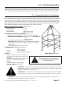
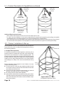
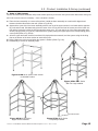
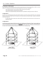
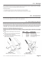
1
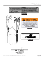
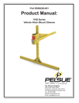
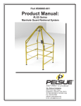
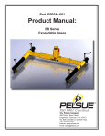
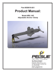
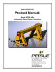
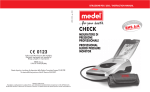
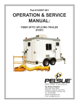
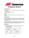
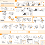
Part #500954-001
Product Manual:
#LGL Series
Manhole Guard Retrieval System
IS O 9 0 0 1 Ce r tifie d
T.A. Pelsue Company
2500 South Tejon Street
Englewood, Colorado, USA 80110
Tel. 800-525-8460 or 303-936-7432
Fax. 303-934-5581
Internet: www.pelsue.com
Email: [email protected]
Page 2
#500954-001 - Product Manual: #LGL Series Manhole Guard Retrieval System - Revision 01 - Date: 10-14-2008
IS O 9 0 0 1 Ce r tifie d
S
ince our inception in 1963 – the T.A. Pelsue
Company has designed and manufactured high
quality equipment to improve the personnel efficiency and working conditions in various underground, confined, and outdoor areas.
Founded by T. Allen Pelsue, the company has established a continuing reputation for excellence in the
production of fine products for a broad spectrum of
industry throughout the world.
Now, in our second generation of family direction,
continued commitment to innovation and quality
makes Pelsue a leading source of equipment for
many types of confined spaces. We specialize
in safety, retrieval, fall arrest, ventilation, cable
placing, splicing, and maintenance nationally and
abroad. With more than 70,000 square feet of facilities available, Pelsue continues the dedication that
has made us pre-eminent in this field.
#500954-001 - Product Manual: #LGL Series Manhole Guard Retrieval System - Revision 01 - Date: 10-14-2008
Page 3
Table of Contents
Section
Description
Page #
1.0......................................General Information..................................5
1.1...........................Quality Policy
1.2...........................Pelsue Product Warranty
2.0......................................Introduction & Product Information........7
2.1...........................Serial Number
3.0......................................Configuration & Assembly........................8
3.1...........................Label Locations
4.0......................................Safety..........................................................10
4.1...........................Warning Statement
4.2...........................Safety Alert Symbol
4.3...........................General Safety Information
4.4...........................Operating Safety
4.5...........................Maintenance Safety
4.6...........................New Operator Safety Information
5.0......................................Product Operation.....................................13
5.1...........................Product Description & Capabilities
5.2...........................Product Installation & Set-Up
5.3...........................Product Operation
6.0......................................Maintenance & Inspection........................17
6.1..........................Maintenance
6.2..........................Inspection
6.3...........................Inspection Log
7.0......................................Storage.......................................................21
8.0......................................Accessories...............................................21
9.0......................................Contact Information..................................23
Page 4
#500954-001 - Product Manual: #LGL Series Manhole Guard Retrieval System - Revision 01 - Date: 10-14-2008
1.0 General Information
1.1 Quality Policy
T.A. Pelsue Company
Quality Policy
OUR GOAL IS THE PURSUIT OF NEVER-ENDING IMPROVEMENT IN
PRODUCT QUALITY AND BUSINESS SYSTEMS.
Methods to be employed in attaining this goal will include
new product quality planning, employee training, and
utilization of employee involvement groups to solve
problems.
In an increasingly competitive marketplace, ensuring
customer satisfaction is one of the differentiators that
sets you apart from the pack and yields a competitive
advantage.
Therefore, we will support total customer satisfaction by
implementing the ISO 9001 Quality System and providing
the necessary atmosphere and training to nurture this
concept throughout our organization.
We will make every business decision as though the quality of
the part or service provided was destined for our own
or our family’s use. We will always think Quality First.
Every T.A. Pelsue Company employee is expected to commit to
this philosophy in the performance of his or her daily tasks.
QUALITY FIRST!
T.A. PELSUE COMPANY SENIOR MANAGEMENT TEAM
#500954-001 - Product Manual: #LGL Series Manhole Guard Retrieval System - Revision 01 - Date: 10-14-2008
Page 5
1.2 - Pelsue Product Warranty
Pelsue products are designed and engineered to perform as stated in published specifications.
Quality materials and workmanship are used in the manufacture of this product. With regular
maintenance and proper care, Pelsue equipment provides many trouble free hours of operation.
The T.A. Pelsue Company warrants to the buyer that the Hoist Product furnished will conform
to specifications and will be free from defects in material and workmanship from the date of
shipment to the original buyer, for a period of 3 months (90 days). In the event of failure of any
components of a Pelsue product within the warranty period, service must be pre-approved by
the T.A. Pelsue Company, and service must be performed by the T.A. Pelsue Parts and Service Department in Englewood, Colorado, or at the option of the T.A. Pelsue Company, service
may be performed at any designated service center, which may include any authorized service
center for the component manufacturer. Unauthorized repairs will not be covered by this warranty.
Damage or failure due to misuse, mishandling, or unauthorized modifications will not be covered
by this warranty. Unless otherwise agreed, the T.A. Pelsue Company shall repair or replace the
defective components within (30) calendar days of notice of failure. T.A. Pelsue Company’s
obligation hereunder, shall be limited to the repair or replacement of the product or component
as set forth above and shall not include any liability whatsoever for damages caused by such
failure, including, but not limited to consequential or incidental damages flowing from use or
lack of use of product.
Any replacement, repair, modification, installation, or other service performed by the T.A. Pelsue
Company shall be warranted by the remainder of the unexpired period of the warranty, or for a
period of (90) calendar days, whichever is longer.
All materials or parts returned for credit or warranty shall be returned only with prior approval,
and will be subject to factory inspection before credit is allowed, Parts claimed defective will
be replaced upon request and will be invoiced as purchased, subject to credit when the parts
claimed to be defective have been received and examined by the factory.
This warranty is expressly in lieu of all other warranties expressed or implied, including any
warranties of merchantability or warranties of fitness for any particular use and all other obligations or liabilities in connection with the sale of this equipment.
T.A. Pelsue Company, 2500 South Tejon Street, Englewood, Colorado 80110, 800-525-8460
Page 6
#500954-001 - Product Manual: #LGL Series Manhole Guard Retrieval System - Revision 01 - Date: 10-14-2008
2.0 - Introduction & Product Information
Congratulations on your choice of a Pelsue Model #LGL Manhole Guard Retrieval System to compliment your confined space entry/retrieval operation. This equipment has been designed and manufactured to exceed confined space
requirements and regulations in order to meet the needs of the discriminating operator for the efficient and safe entry or
retrieval of personnel from a confined space.
Safe, efficient and trouble-free operation and maintenance of the system requires that anyone who will be operating,
maintaining, or inspecting the equipment, read, understand and follow all the operation, safety, maintenance, and inspection instructions contained within this manual. This manual covers the Pelsue Model #LGL Manhole Guard Retrieval
System. Use the Table of Contents as a guide to find specific information.
Keep this manual handy for frequent reference and to pass on to new operators. Establish a regular training program
for experienced and new operators per this manual. Establish a regular maintenance and inspection program to keep
the equipment in top condition.
This product is a part of a man rated confined space
entry/retrieval system. The user must read, understand
and follow the instructions contained in this manual
for each component or total system before using
this equipment. Establish an appropriate training,
maintenance and inspection program for your people
and the equipment. Failure to follow these instructions
could result in serious injury or death.
2.1 - Serial Number
Product Serial Number
Always give your dealer the serial number of your Pelsue
confined space entry/retrieval product when ordering parts or
requesting service or other information.
SERIAL
NUMBER
LOCATION
The serial number decal is permanently embossed with a serial
number. The serial number decal will appear as shown in Figure
2a at the bottom. On the upper section it will be located on one
of the front vertical legs (see Fig. 2b). On the lower section it
will be located on the top rear cross bar (see Fig. 2c). A space
has been provided below for the recording of the serial numbers
for future reference.
Upper Assembly
Guard
Fig. 2b: Upper Assembly
Serial Number Decal Location
MODEL:
SERIAL
NUMBER
LOCATION
Serial Number :
Date of
Manufacture (DOM):
Figure 2a: Serial
Number Decal
#500954-001 - Product Manual: #LGL Series Manhole Guard Retrieval System - Revision 01 - Date: 10-14-2008
Fig. 2c: Guard
Serial Number Decal Location
Page 7
3.0 - Configuration & Assembly
Upon initial receipt of the Manhole Guard Retrieval System, inspect the packaging for any evidence that the product
may have been damaged in shipment. While unpacking the product, inspect all of the components for damage. If
damage to any of the components is discovered, DO NOT USE THE PRODUCT! Alert the shipping carrier immediately
of the damage to the shipment.
ITEM#
LGL-TA
LGL-GA
1.
2.
PART#
500878-001 P102
P025
DESCRIPTION
LGL UPPER SECTION
CARABINER - GALVANIZED STEEL, SCREW LOCK
PULLEY - CABLE READY, 2-1/2” TREAD, ALUMINUM
500920G-001 LGL LOWER SECTION
1
2
LGL-TA FOLDED ORIENTATION
LGL-TA DEPLOYED ORIENTATION
LGL-GA FOLDED ORIENTATION
LGL-GA DEPLOYED ORIENTATION
Figure 3.0: #LGL Series
Configuration Diagram
Verify that all parts are present before completing assembly.
The Carabiner and Pulley will not be installed on the upper assembly upon receipt. To fully assemble the upper section,
1. Secure the Screw Lock Carabiner (#1) to a Swivel Eye located on the Hub of the upper section by unscrewing the
screw lock on the Carabiner, and hooking through the Swivel Eye.
2. Hook the Cable Ready Pulley (#2) onto the Carabiner (#1) and fully tighten the Screw Lock on the Carabiner.
**Refer to parts list above if replacement parts are required. Replacement parts can be ordered from the T.A. Pelsue
Company at 800-525-8460.
Page 8
#500954-001 - Product Manual: #LGL Series Manhole Guard Retrieval System - Revision 01 - Date: 10-14-2008
3.1 Label Locations
1) 500953-001
2
2) 500234-001
3
1
MANUFACTURED BY
T.A. PELSUE CO. ENGLEWOOD, COLORADO 80110
3) 102072-002
Figure 3.1a: #LGL-TA
Label Locations
#500954-001 - Product Manual: #LGL Series Manhole Guard Retrieval System - Revision 01 - Date: 10-14-2008
Page 9
4.0 - Safety
The following section will address the safety precautions which must be adhered to when working with Pelsue confined
Space Safety equipment such as the #LGL Series Manhole Guard Retrieval System. Any user must familiarize themselves with the information in this section before utilizing the equipment.
SIGNAL WORDS:
Note the use of the signal words DANGER, WARNING and CAUTION with the safety messages. The appropriate signal
word for each message has been selected using the following guidelines:
DANGER-
Indicates an imminently hazardous situation that, if not avoided, will result in death or serious injury. This
signal word is to be limited to the most extreme situations or for hidden or unseen hazards.
WARNING- Indicates a potentially hazardous situation that, if not avoided, could result in death or serious injury and
includes obvious and hidden hazards. It may also be used to alert against unsafe practices.
CAUTION-
Indicates a potentially hazardous situation that, if not avoided, may result in minor or moderate injury. It
may also be used to alert against unsafe practices.
You are responsible for the safe operation, maintenance and inspection of your Pelsue #LGL Manhole Guard Retrieval
System. You must ensure that anyone who will operate, maintain, inspect or work around the equipment be familiar
with the operating and maintenance procedures and related safety information contained in this manual. This manual
will take you step-by-step through the workings and capabilities of the #LGL Manhole Guard System and alert you to all
good safety and operating practices while using the system.
Remember, you are the key to safety. Good safety practices not only protect you but also the people around you. Make
these practices a working part of your safety program. Be certain that everyone operating this equipment is familiar with
the procedures recommended and follows safety precautions. Remember, most accidents can be prevented. Do not risk
injury or death by ignoring good safety practices.
•
System owners must give operating instructions to operators or employees before allowing them to use the
equipment and at least annually thereafter.
•
The most important safety device on this equipment is a safe operator. It is the operator’s responsibility to read
and understand all safety and operating instructions in the manual and to follow these. Most accidents can be
avoided.
•
A person must understand the operation of this equipment and be trained in it’s usage before operating the
equipment. An untrained operator exposes himself and others to possible serious injury or death.
•
Do not modify the equipment in any way. Unauthorized modification may impair the function and/or safety and
could affect the life of the equipment.
•
Think SAFETY! Work SAFELY!
4.1 - Warning Statement
WARNING!
Products manufactured or sold by the T.A. Pelsue Company are
intended for use by professionals trained and experienced in the
use, inspection and maintenance of these products.
Paraprofessional users such as volunteer rescue workers and
sportsmen involved in risk sports such as climbing and caving will
be held to the same standard of experience and training as professionals.
Technical rescue, repelling, climbing and the training involved are
hazardous activities. Each situation has its own unique conditions
and must be evaluated. Effective risk management comes from
experience, proper training and good personal judgement.
Page 10
7!2.).'
Failure to read and heed all labels and instructions may
result in injury or death. Inspect all components before
and after each use, and remove from service if any
damage or defect is found. Keep product free from dirt
and moisture.
Do not leave a suspended load
unattended. Do not exceed maximum rated loads.
#500954-001 - Product Manual: #LGL Series Manhole Guard Retrieval System - Revision 01 - Date: 10-14-2008
4.2 - Safety Alert Symbol
SAFETY ALERT SYMBOL
This Safety Alert symbol means ATTENTION! BECOME
ALERT! YOUR SAFETY IS INVOLVED!
The Safety Alert symbol identifies important safety messages
on your Pelsue Retrieval Product and in the manual. When
you see this symbol, be alert to the possibility of personal
injury or death. Follow the instruction in the safety message.
Why is this symbol important to you?
3 BIG Reasons:
Accidents Disable and Kill.
Accidents Cost You Money.
Accidents Can Be Avoided.
4.3 - General Safety Information
1. Read, understand, and follow the Product Manual and all safety signs before using, maintaining or inspecting the
equipment.
2. Refer to and follow applicable standards and regulations. Comply with requirements of local regulations for your
applications.
3. Establish an equipment-use training program for inexperienced employees. Only trained, competent persons shall
use the equipment. An untrained operator is not qualified to operate the system.
4. Have a first-aid kit available for use should the need arise and know how to use it.
5. Provide a fire extinguisher for use in case of an accident. Store in a highly visible place.
6. Install and properly secure all guards and shields before operating.
7. Wear appropriate protective gear. This list includes but is not limited to:
• A hard hat
• Protective shoes with slip resistant soles
• Heavy gloves
• Protective clothing
• Face Protection
8. Review and follow the Pre-Operation Checklist before using a component in the system or the system itself.
9. Establish a regular maintenance and inspection program with your equipment and maintain detailed records.
10.Review safety related items and operating instructions with all personnel on a regular basis.
4.4 - Operating Safety
1.
Read, understand and follow the User Manual and signs on the product before using, maintaining or inspecting the equipment.
2.
Train all operators before allowing them to use the product. An untrained operator exposes themselves, bystanders
and workers to possible serious injury or death.
3.
Visually inspect the product and all auxiliary components and equipment before using. Correct any problems before
using the equipment.
4.
Securely anchor the product before using.
5.
Use only certified anchor and connector components in your system.
6.
Use only an approved full body harness for the workers.
#500954-001 - Product Manual: #LGL Series Manhole Guard Retrieval System - Revision 01 - Date: 10-14-2008
Page 11
4.4 - Operating Safety (continued)
7.
Always work in teams. One person is to work in the confined space (entrant) and the other is to attend to the entrant
(attendant). Pelsue recommends an additional attendant/rescuer for stand-by in case of an emergency.
8.
Do not exceed the capacity of the system at any time (see section 5.1).
9.
Establish a regular training program for new and experienced workers.
10. Establish a detailed inspection program for your equipment and document the findings. Return the equipment to
the manufacturer for repair if any problems are found.
11. Plan your work program before starting. Have the required people, equipment and procedures available to do the
job.
12. Do not use the equipment around physical or environmental hazards. This list includes but is not limited to:
• Corrosion that may affect the structural integrity of the lifeline or other components.
• Chemicals which can degrade components in a manner which can not be visually identified.
• Toxic gases: Rescuers or workers can be killed in toxic environments.
• Heat or elevated temperatures.
• Moving machinery: Workers or auxiliary equipment can be contacted by or pulled into moving components.
• Sharp edges: Workers or the rescue equipment can be injured by or damaged by sharp edges or components.
• Electrical hazards: Stay away from power lines or components carrying electrical power.
• Overload: Do not overload the system at any time during operation (see section 5.1).
• Follow confined space regulations and standards.
4.5 - Maintenance Safety
1. Read, understand and follow the User Manual and signs on the product before using, maintaining or inspecting the equipment.
2. ANSI and OSHA require a regular inspection program for all confined space entry/retrieval equipment and to maintain documented results of these inspections. Follow the inspection procedure contained in this manual and use
the inspection form to document the results (see section 6.0).
3.Keep instructional and safety signs clean and legible at all times. Clean or replace as required.
4. Remove the equipment from service if a problem is found during the inspection. Return to an authorized repair depot
or the factory for service.
4.6 - New Operator or Owner
The Pelsue #LGL Series Manhole Guard Retrieval Systems are designed to assist a person/entrant in entering a confined space and assist in exiting if required. Every new operator must read, understand and follow the instructions in the
manual. No one should be allowed to use the equipment without training. The training should be reviewed with experienced operators on a regular basis. At regular intervals, perform a detailed inspection of the equipment and document
the results. Remove from service if deficiencies are found. Alterations or misuse of this equipment or failure to follow
instructions may result in serious injury or death.
It is the responsibility of the owner’s organization or operator to read this manual and to train all other operators before
they start working with the equipment. Follow all safety instructions exactly. Safety is everyone’s business. By following
recommended procedures, a safe working environment is provided for the operator, bystanders and the area around
the work site. Untrained operators are not qualified to operate the equipment.
Many features incorporated into this equipment are the result of suggestions made by customers like you. Read this
manual carefully to learn how to operate the equipment safely and how to set it to perform as intended. By following the
operating instructions in conjunction with a good maintenance program, your product will provide many years of trouble
free service.
Page 12
#500954-001 - Product Manual: #LGL Series Manhole Guard Retrieval System - Revision 01 - Date: 10-14-2008
5.0 - Product Operation
The following section will address the capabilities and the general operation of the Pelsue #LGL Series Manhole Guard
Retrieval System. The instructions contained within this section should be adhered to each and every time the product is
used. Any person tasked with installing or operating the piece of equipment should be familiar with these procedures.
5.1 - Product Description & Capabilities
The Pelsue #LGL Series Manhole Guard Retrieval Systems are built from structural aluminum, and have steel hardware
and engineered plastic components. LGL Manhole Guard Retrieval Systems are specifically designed for confined
space entry and/or rescue & retrieval applications. All specifications, instructions, and procedures provided within this
manual or upon Pelsue Specification Documents are based upon and only valid for usage with a Pelsue Manhole Guard
Retrieval System approved accessories. The T.A. Pelsue Company can not verify equipment safety and/or compliance
when utilized with anything other than Pelsue approved LGL Series accessories.
Manhole Guard Retrieval System - #LGL Series
General Specifications
• System Footprint
-
42” x 42”
• Overall Height
-
76-3/4”
• Structure Weight
-
Upper Section 23 lbs
Lower Section 30 lbs
Load Rating & Compliance (2 applications)
1. Rated for personnel lifting or lowering applications for a single user.
• Man Rated Load Capacity.....Single User of 350 LBS.(159
KG.)
Maximum Weight
2. As an anchorage for a personal fall arrest system
Warning! A 900 LB. maximum arrest force (MAF) fall arrest device
must be used when system is employed as part of a complete fall
arrest system.
**Refer to loading diagrams for proof load
Materials & Construction
• Main Structure:
- Structural Aluminum
(Powder coated)
• Chains
- Zinc Plated Steel
• Hardware
- Grade 5 & Grade 8 (plated)
Figure #5.1a: #LGL Series
Features:
• Easily assembles over most manholes for
safe and secure lifting and/or placement of
personnel
The load rating given here may supersede
• Provides a multi-position winch mount comany
load rating reported for an installed winch
patible with many winch and fall arrest
and or pulley system.
Systems
• Constructed primarily of lightweight &
Corrosion-resistant powder coated
Aluminum & Steel
! CAUTION ! - The user must ensure that the ground area utilized for operation is capable of
withstanding the weight of the system combined with the system proof loads in order to retain
the stated compliance of the entire system.
! CAUTION ! - The user must ensure that the ground area utilized for operation is relatively
level and debris free in order to retain the stated compliance and stability of the entire system.
! CAUTION ! - The user must ensure that the safety chains on the Guard Assembly are secure and intact in
order to retain the stated compliance of the entire system.
#500954-001 - Product Manual: #LGL Series Manhole Guard Retrieval System - Revision 01 - Date: 10-14-2008
Page 13
5.1 - Product Description & Capabilities (continued)
TEST LOAD
APPLIED AS
SHOWN
TEST LOAD
APPLIED AS
SHOWN
1800 LB.
[816 KG]
PROOF LOAD
1800 LB.
[861 KG]
PROOF LOAD
Figure 5.1b: LGL
Loading Diagram
Configuration 1
Figure 5.1c: LGL
Loading Diagram
Configuration 2
Additional Requirements & Notes
• #LGL Series Guard System must be set on a level surface prior to use.
• In order to ensure compliance, it is the user’s responsibility to ensure that the supporting surroundings are capable
of withstanding all of the loads imparted to it by the proof-loaded #LGL Guard System.
• #LGL Series are only to be utilized within the guidelines and ratings presented in this manual and only by personnel
who are trained in the operation of this equipment as well as the practices of general confined space safety.
5.2 - Product Installation & Set-up
Prior to Operation, the #LGL Series Rescue & Retrieval Manhole
Guard System should be configured and prepared according to
the following guidelines.
APEX HUB
1. Pre-Operation Inspection:
It is necessary to perform a visual inspection, each time, prior to
using the product. If deficiencies are found, remove the product
from service and contact the T.A. Pelsue regarding repair. The
following checklist coupled with Figure #5.2a should be used as
a guide to determine whether the equipment is in good operating
condition prior to usage. Equipment that is not in good condition
can endanger the safety of the entrant and attendant during
use.
The Pre-Operation Visual Inspection is not limited to, but must
include the following items;
a. Check that all the cross bars are straight and that all welds
do not have cracks or fractures. Be certain that all cross bars
are solidly mounted & secure.
b. Check that the apex-mounted anchor-points are fastened
securely to the apex structure, and swivel freely.
c. All leveling feet are present and adjustable.
d. Verify that the safety chains are present on the guard. (Note:
The safety chains on the guard are a load bearing mechanism
and must be attached to the tabs to retain the stated compliance of the system.)
Page 14
SAFETY
CHAINS
LEVELING FEET
Figure #5.2a: #LGL Series
Pre-Operation Inspection Points
#500954-001 - Product Manual: #LGL Series Manhole Guard Retrieval System - Revision 01 - Date: 10-14-2008
5.2 - Product Installation & Set-up (continued)
2. Setup of LGL System:
Choose a location where installation will provide suitable proximity to the work area yet minimize obstructions during use
and in the event a rescue is necessary. Once a location is chosen;
a. Place the lower assembly on a secure flat surface. Unfold the lower assembly as to make a 90 degree bend
between the side rails and the rear rails. (Refer to Fig #5.2b).
b. Approach the open side of the lower assembly with the one leg of the upper section in one hand and the opposite
leg in the other hand. Simultaneously place the insert of the one leg into the front left corner post of the lower section and the insert of the other leg into the opposite corner post. You can now let go of the upper assembly and it
will stay upright (Refer to Fig #5.2c). Walk around the system placing the upper legs into the corresponding guard
corner posts (Refer to Fig. #5.2d).
c. After the upper and lower sections have been fully deployed and connected, level the system using the leveling feet on the bottom of the lower section at each corner post.
d. Safety Chains are to be secured when the system is loaded. (Refer Fig. 5.2e).
e. Disassembly is reverse of assembly steps.
Figure #5.2b: #LGL Series Lower Section
In Unfolded Position
Figure #5.2c: #LGL Series
With Two Legs Installed.
TABS
LEVELING FEET
Figure #5.2d: #LGL Series
Upper Section Installed.
Figure #5.2e: #LGL Series
Completely Installed.
#500954-001 - Product Manual: #LGL Series Manhole Guard Retrieval System - Revision 01 - Date: 10-14-2008
Page 15
5.3 - Product Operation
1. Operation of LGL System:
Before operation of the LGL System can occur, the user must choose one of two configurations in which to use the
system. The configuration should be chosen and configured before any entry is attempted.
- Ensure that the system is secure and level before working over the manway.
- Ensure that the system is centered over the manway.
- Always secure the guards safety chains when there is a potential for loading of the winch or SRL line
Configuration 1
An SRL device (Self Retracting Lifeline) with an MAF (maximum arrest force) rating of 900 LBS. can be connected
directly to one of the Overhead Anchor Points present on the Apex Hub (Fig. #5.2b) providing a compliant overhead fall
arrest anchorage point.
- To connect the SRL to the Apex Hub, utilize the SRL’s connector to secure the device to one of the two overhead anchor points.
Configuration 2
A single winch accessory bracket (#LGL-B) is included and installed on each LGL system. This accessory enables the
use of a standard personnel winch. Please refer to Section 8.0 for details on the winch installation. In this scenario, the
winch will be attached at the winch bracket on the upper section and the cable will be reeved up and over the pulley at
the apex which will provide a lifting & lowering line centered over the manway opening.
Standard SRL
Figure #5.3a:
#LGL Over Manway
Page 16
Figure #5.3b:
Configuration 1
#500954-001 - Product Manual: #LGL Series Manhole Guard Retrieval System - Revision 01 - Date: 10-14-2008
6.0 - Maintenance & Inspection
MAINTENANCE & INSPECTION
1.
2.
Read, understand and follow the Product Manual and signs 3.Keep instructional and safety signs clean and legible at
on the product before using, maintaining or inspecting the
all times. Clean or replace as required.
equipment.
4. Remove the equipment from service if a problem is found
ANSI and OSHA require a regular inspection program
during the inspection. Return to an authorized repair depot
for all confined space entry/retrieval equipment and to
or the factory for service.
maintain documented results of these inspections. Follow
the inspection procedure contained in this manual and
use the inspection form to document the results.
6.1 - Maintenance
For the most part, the Model #LGL is intended to be a maintenance-free piece of equipment, however several steps can
be taken to keep the system in top-notch working order and also extend the working life of the product.
Before Each Use:
1. V
isual Inspection: Perform a complete visual inspection. Refer to section 6.2 for guidelines and take any
maintenance steps that are necessary.
Annually:
1. C
lean Product: Use a damp cloth and mild soap to clean the structure and labels of dirt and residue. Be sure
the labels are legible (replacements are available from Pelsue)
2. C
omplete Inspection: Perform a thorough inspection, paying attention to the bullet points provided within
section 6.2. Record results and keep documentation. A log has been provided in section 6.3 specifically for
the recording of the dates & results of annual system inspections.
Periodic Factory Service Inspection: It is recommended that the product be serviced by a factory authorized
service center or the manufacturer after a period of three years. Extreme working conditions may indicate
the necessity to increase the frequency. Factory servicing shall include but not be limited to an intensive
inspection and cleaning of all internal and external components. Failure to provide proper service may shorten
product life and could endanger performance or function.
6.2 - Inspection
When completing an inspection of the Model #LGL Manhole Guard Retrieval System, the following specific items should
be checked;
1. Labels:
Check that all the labels are clean and legible (Refer to Section 3.1). Clean the labels if any are dirty using mild
soap and a damp cloth. Replace if any are illegible. Decals & labels provide valuable warning and caution information applicable to product usage and limitations, and should be visible and present at all times.
2. Fasteners: Check that all screws and other fasteners are present and secure. Note that not all fasteners are tightened to their
maximum allowable torque. This is done in order to allow for pivoting and folding motions in certain components.
Over-tightening of fasteners can interfere with the operation of the device and can damage the structure.
All fasteners on the Model #LGL system are of a self-locking design. Bolt threads should extend all the way though
their locking nuts. If any fasteners have appeared to “back-out” or loosen the product should be removed from
service until the problem can be identified and corrected.
#500954-001 - Product Manual: #LGL Series Manhole Guard Retrieval System - Revision 01 - Date: 10-14-2008
Page 17
6.2 - Inspection (continued)
3. Overhead Anchor Points:
Ensure that the two overhead anchor points swivel freely and that there is no binding in their range of motion. Also,
visually inspect the anchor lugs for any sign of deformation. The anchor lugs can elongate and stretch if overloaded
beyond the capacity of the system. Any Model #LGL system exhibiting deformation in the anchor lugs should be
removed from service immediately.
4. Structure:
The entire product structure should be checked for cracks, dents, bends or breaks. If there are major dents or any
other structural damage, the unit should be removed from service and returned to the factory for repair.
• Pay special attention to weld locations: look for cracks or separation at the welds. Keep in mind the powder
coating can age and crack, this normal paint cracking can be confused with structural cracking. If there is any
uncertainty with regards to cracks, contact the Pelsue service department for assistance and/or recommendations
• Ensure that the upper and lower assemblies can be separated and folded as intended. Inability, or difficulty in
folding the structure as intended may be indicative of structural damage. If the unit fails to fold or stow as intended
remove the product from service and investigate further.
Page 18
#500954-001 - Product Manual: #LGL Series Manhole Guard Retrieval System - Revision 01 - Date: 10-14-2008
#LGL
#500954-001 - Product Manual: #LGL Series Manhole Guard Retrieval System - Revision 01 - Date: 10-14-2008
Inspector (print & sign) :
Inspector (print & sign) :
Inspector (print & sign) :
Inspector (print & sign) :
Inspector (print & sign) :
Inspector (print & sign) :
Inspector (print & sign) :
Inspector (print & sign) :
Date
labels
Pins & Fasteners
Overhead Anchor
Points
Overall Structure
Place a check (¥ in the box if item is acceptable, place an x (X) in the box if item requires maintenance or repair
model Number :
Serial Number :
Date Purchased :
Notes
6.3 - Inspection Log
Page 19
Page 20
Inspector (print & sign) :
Inspector (print & sign) :
Inspector (print & sign) :
Inspector (print & sign) :
Inspector (print & sign) :
Inspector (print & sign) :
Inspector (print & sign) :
Inspector (print & sign) :
Inspector (print & sign) :
Date
labels
Pins & Fasteners
Overhead Anchor
Points
Overall Structure
Notes
6.3 - Inspection Log (continued)
#500954-001 - Product Manual: #LGL Series Manhole Guard Retrieval System - Revision 01 - Date: 10-14-2008
7.0 - Storage
Prior to storage, the product should be thoroughly inspected and maintained. Repair or replace any worn or damaged
components to prevent any unnecessary down time at the next use.
Follow this procedure:
1. Thoroughly clean the entire unit using a mild soap on the frame and labels.
2. Perform a complete inspection of the unit and document the results prior to storage.
8.0 - Accessories
This section of the product manual will address optional accessories available from Pelsue for the LGL Series System
that can extend the capabilities of the system in various applications
8.1 - #LGL-B Mounting Bracket
Each LGL system includes a single winch mounting bracket. Multiple winch mounts may be attached and are available
from Pelsue as part #LGL-B. The winch bracket may be attached to any of the four legs of the LGL’s upper assembly which
are pre-drilled for this specific purpose. Multiple brackets allow the fastening of multiple winch options simultaneously.
! CAUTION - only one winch may be utilized and loaded at any one time when installed on the LGL system !
Installation of the Winch Mounting Parts (Part 1):
Installation of the winch mount should be performed prior to usage in an area not subject to fall hazards. Once installed,
the platform and bracket can remain on the unit indefinitely, the upper assembly can be stowed with the winch adapter
installed.
ITEM#
PART#
DESCRIPTION
a. First choose the desired leg for winch mount loca1.
500101-002
WELDMENT - WINCH BRACKET
tion.
2.
500890-001
MOUNTING PLATE
b. Fasten the winch mounting platform with the neces3.
100163-015
3/8”-16 X 2-3/4” BOLT
sary hardware (Refer to Fig #8.1a).
4.
100163-009
3/8”-16 X 1-1/4” BOLT
c. Then fasten the winch bracket on to the mounting
5.
107943-001
3/8”-16 STOVER LOCKING NUT
platform (Refer to Fig #8.1b).
6.
100050-011
FLAT WASHER - 3/8”
2
4
3
6
1
5
5
6
Figure #8.1a
Mounting Platform Installation
Figure #8.1b
Winch Bracket Installation
#500954-001 - Product Manual: #LGL Series Manhole Guard Retrieval System - Revision 01 - Date: 10-14-2008
Page 21
8.1 - LGL-B Mounting Bracket (continued)
Installation of the Winch to Adapter (Part 2):
Note: The #LGL-B bracket will accept any Pelsue PW Series winch that is outfitted with a standard quick-release
bracket
a.
b.
c.
d.
Before Installing the winch, ensure that the LGL system is assembled correctly.
First slide the open slot of the Winch mount onto the welded bar on the Winch adapter (Fig. #8c).
Then line up the holes on the Winch mount and the Winch adapter and insert the provided detent Pin.
A quantity of winch cable can now be payed out so that the winch line can be reeved over the Pulley that is included
with the LGL system ( Fig. #5.1a ). Ensure that the pulley and carabiner are properly fastened to an overhead anchor
point and Operate the system within the limits of the LGL system & the winch.
Note: If required, a secondary Fall arrest System can be attached to the second swivel eye at the apex in correspondence to the manufacture’s instructions for that device.
! CAUTION !
Pelsue can only verify compliance & compatibility of the Model #LGL-B winch bracket with Pelsue PW Series
Winches.
Figure #8.1c
Winch Installation Step 01
Figure #8.1d
Winch Installation Step 02
Figure #8.1e
Winch Installation Step 03
Page 22
#500954-001 - Product Manual: #LGL Series Manhole Guard Retrieval System - Revision 01 - Date: 10-14-2008
9.0 - Contact Information
For More Information...
T.A. Pelsue Company
2500 S. Tejon St.
Englewood, CO 80110
Toll Free:
Telephone:
Fax:
1-800-525-8460
1-303-936-7432
1-303-934-5581
Website:
www.pelsue.com
Email:
[email protected]
#500954-001 - Product Manual: #LGL Series Manhole Guard Retrieval System - Revision 01 - Date: 10-14-2008
Page 23
ISO 90 0 1 C e rt i f i e d
T.A. Pelsue Company
2500 South Tejon Street, Englewood, Colorado, USA 80110
Toll free 800-525-8460 or 303-936-7432 Fax. 303-934-5581
Internet: www.pelsue.com Email: [email protected]