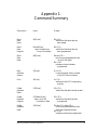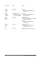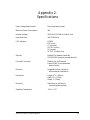
1
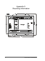
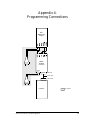
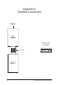
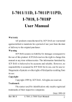
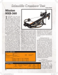
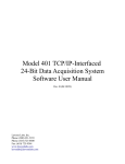
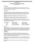
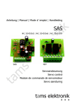
Modbus Plus Adapter EIG Model MP1, a Modbus Plus adapter for DMMS 300+ and Futura+ Monitors User Manual and Reference Guide Version 1.6 Modbus Plus Adapter User Manual and Reference Guide Version 1.6 Pub lished by: Elec tro In dus tries/GaugeTech 1800 Shames Drive West bury, NY 11590 All rights re served. No part of this pub li ca tion may be re pro duced or trans mit ted in any form or by any means, electronic or me chani cal, in clud ing pho to copy ing, re cord ing, or in for ma tion stor age or re trieval sys tems or any fu ture forms of du pli ca tion, for any pur pose other than the pur chas er’s use, with out the ex pressed writ ten per mis sion of Elec tro Industries/GaugeTech. 1998 Elec tro In dus tries/GaugeTech Released November 1998 Printed in the United States of America Modbus and Modbus Plus are registered trademarks of Schneider Automation, Inc. Cus tomer Serv ice and Sup port Cus tomer sup port is avail able 9:00 a.m. to 4:30 p.m., east ern stan dard time, Mon day through Fri day. Please have the model, se rial number and a de tailed prob lem de scrip tion avail able. If the prob lem con cerns a par ticu lar read ing, please have all me ter read ings available. When re turn ing any mer chan dise to EIG, a re turn authori za tion number is re quired. For cus tomer or tech ni cal as sis tance, re pair or cali bra tion, phone 516-334-0870 or fax 516-338-4741. Prod uct Warranty Elec tro In dus tries/GaugeTech war rants all prod ucts to be free of de fects in ma te rial and work man ship for one year from the date of ship ment. Dur ing the war ranty pe riod, we will, at our op tion, re pair or re place any prod uct that proves to be de fec tive. To ex er cise this war ranty, fax or call our customer- service de part ment. You will re ceive prompt as sis tance. Send the in stru ment, trans por ta tion pre paid, to Elec tro In dus tries/ GaugeTech at 1800 Shames Drive, West bury, NY 11590. Re pairs will be made and the instrument will be re turned. Limitation of Warranty This war ranty does not ap ply to de fects re sult ing from un au thor ized modi fi ca tion, mis use, or use for any rea son other than elec tri cal power moni tor ing. OUR PRODUCTS ARE NOT TO BE USED FOR PRIMARY OVER-CURRENT PROTECTION. ANY PROTECTION FEATURES IN OUR PRODUCTS ARE TO BE USED FOR ALARM OR SECONDARY PROTECTION ONLY. THIS WARRANTY IS IN LIEU OF ALL OTHER WARRANTIES, EXPRESSED OR IMPLIED, INCLUDING ANY IMPLIED WARRANTY OF MERCHANTABILITY OR FITNESS FOR A PARTICULAR PURPOSE. ELECTRO INDUSTRIES/GAUGETECH SHALL NOT BE LIABLE FOR ANY INDIRECT, SPECIAL OR CONSEQUENTIAL DAMAGES ARISING FROM ANY AUTHORIZED OR UNAUTHORIZED USE OF ANY ELECTRO INDUSTRIES/GAUGETECH PRODUCT. LIABILITY SHALL BE LIMITED TO THE ORIGINAL COST OF THE PRODUCT. State ment of Cali bration Our in stru ments are in spected and tested in ac cor dance with speci fi ca tions pub lished by Electro In dus tries/GaugeTech. The ac cu racy and cali bra tion of our in stru ments are trace able to the Na tional Bu reau of Stan dards through equip ment that is cali brated at planned in ter vals by com pari son to cer ti fied stan dards. Disclaimer The in for ma tion pre sented in this pub li ca tion has been care fully checked for re li abil ity; however, no re spon si bil ity is as sumed for in ac cu ra cies. The in for ma tion con tained in this document is sub ject to change with out no tice. Elec tro In dus tries/GaugeTech i. ii. Elec tro In dus tries/GaugeTech Electro Industries/ GaugeTech Elec tro In dus tries/GaugeTech was founded in 1973 by en gi neer and in ven tor Sam uel Ka gan. Dr. Ka gan’s first in no va tion, which revo lu tion ized the power- monitoring field, was the de vel op ment of an af ford able, easy- to- use AC power me ter. In the 1980s, Dr. Ka gan and his team at EIG de vel oped a digi tal mul ti func tion moni tor. This moni tor, with its abil ity to meas ure every as pect of power, trans formed AC power me ter ing and power dis tri bu tion. Un der Dr. Ka gan’s lead er ship, EIG again de vel oped a prod uct that sur passed everything else on the mar ket: the Fu tura+ de vice. It sup plied all the func tion al ity of a fault re corder, an event re corder and a data log ger in the con figu ra tion of a sin gle me ter. To day, as a leader in the de vel op ment and pro duc tion of power- monitoring prod ucts, EIG aspires to at tain zero- defect manu fac tur ing. Elec tro In dus tries/GaugeTech iii. Products All of EIG’s prod ucts are de signed, manu fac tured, tested and cali brated at our fa cil ity in West bury, New York. EIG manu fac tures the most so phis ti cated digi tal power moni tors avail able. Our prod ucts han dle such things as: n Mul ti func tion power moni tor ing n Power- quality moni tor ing n On board data log ging for trending power usage and quality n Dis tur bance analy sis EIG manu fac tures both sin gle and mul ti func tion digi tal power moni tors. These utility- grade de vices are highly re li able and so phis ti cated. Futura+ Series As the ul ti mate power- quality moni tor, the Fu tura+ is widely used at auto mated sub sta tions. In addition to having nearly all of the capabilities of DM meters, it also handles: n Power- quality moni tor ing n High- accuracy AC me ter ing n On board data log ging n On board fault and voltage re cord ing n Ten channels of analog outputs DM Se ries DM meters are the sub sta tion stan dard for many utili ties and large in dus tri al companies. These three-phase multifunction monitors meas ure every as pect of power. n Watt age, voltage, amperage, var, VA, power factor, frequency and harmonics (%THD) n P rotocols: Mod bus, Modbus Plus, DNP 3.0 and Ethernet n A na log outputs (0- 1 and 4- 20mA) iv. Elec tro In dus tries/GaugeTech Single- Function Me ters n AC volt age and am per age n DC volt age and am per age n AC watt age n Single- phase moni tor ing with maxi mum and mini mum de mands n Trans ducer read outs Portable Analyzers n Power-quality analysis n Energy analysis Elec tro In dus tries/GaugeTech v. vi. Elec tro In dus tries/GaugeTech Table of Contents Overview Introduction . . . . . . . . . . . . . . . . . . . . . . . . . . . . . 1 Installation . . . . . . . . . . . . . . . . . . . . . . . . . . . . . . 2 MP1 Installation . . . . . . . . . . . . . . . . . . . . . . . . . 2 Meter Installation . . . . . . . . . . . . . . . . . . . . . . . . 2 Operating Modes . . . . . . . . . . . . . . . . . . . . . . . . . . . 3 Normal Mode . . . . . . . . . . . . . . . . . . . . . . . . . . 3 Program Mode . . . . . . . . . . . . . . . . . . . . . . . . . . 3 Programming the MP1 . . . . . . . . . . . . . . . . . . . . . . . . . 4 Program-Mode Commands . . . . . . . . . . . . . . . . . . . . . . . 5 Operation Baud Rate . . . . . . . . . . . . . . . . . . . . . . . . . . . 5 Boot Software Version . . . . . . . . . . . . . . . . . . . . . . . 5 Echo . . . . . . . . . . . . . . . . . . . . . . . . . . . . . . 5 Global Registers . . . . . . . . . . . . . . . . . . . . . . . . . 6 Meter Address . . . . . . . . . . . . . . . . . . . . . . . . . . 6 Product Code . . . . . . . . . . . . . . . . . . . . . . . . . . 7 Resetting the MP1 . . . . . . . . . . . . . . . . . . . . . . . . 7 Appendices Appendix 1: Command Summary . . . . . . . . . . . . . . . . . . . . 8 Appendix 2: Specifications . . . . . . . . . . . . . . . . . . . . . . . 10 Appendix 3: Mounting Information . . . . . . . . . . . . . . . . . . . . 11 Appendix 4: Programming Connections . . . . . . . . . . . . . . . . . . 12 Appendix 5: Standard Connections . . . . . . . . . . . . . . . . . . . . 13 Elec tro In dus tries/GaugeTech vii. viii. Elec tro In dus tries/GaugeTech Overview Introduction The Modbus Plus Adapter (MP1) is handy gadget that allows a Futura+ or DMMS 300+ monitor to communicate over a Modbus Plus network. The monitor becomes just another node on the network: It can take full advantage of the speed of the Modbus Plus architecture. A monitor equipped with an MP1 can be polled by other nodes on the same network, or by nodes on adjacent bridged networks. The MP1 can be configured to globally broadcast any 32 registers of information. This rugged device is opto isolated and features an upgradable flash RAM. Use the MP1 to: n Con vert Mod bus to Mod bus Plus. n Poll me ters for Mod bus Plus global vari ables and pres ent them to a Mod bus Plus network. n Program: • The meter address. • The meter baud rate. • The global variables to poll. n Read the meter’s Modbus Plus address (which is set with its top switches). To program the MP1, all you need is the MP Cable and an RS485 two-wire terminal interface operating at 19.2 kilobaud. Just connect the MP1 between the monitor and the network, and you’re off and running. Elec tro In dus tries/GaugeTech 1. Installation The Modbus Plus Adapter supports a single meter in register polling and global variables. Use a terminal interface to program the global variables, meter address and baud rate. MP1 Installation n Set the MP1’s address to 1 (1,0). n Slide the MP1’s PROG/NORM switch to NORM. n Plug the 5-pin meter connector cable (MP Cable) into both the meter and the MP1. n Attach the DB9-female connector to the Modbus Plus network. Meter Installation Most meters can be used right out of the box, because the required settings are the default values. If necessary: n Set the meter address to 1. n Set the baud rate to 9600. n Set the protocol to Modbus RTU. 2. Elec tro In dus tries/GaugeTech Operation Operating Modes Normal Mode In Normal mode, the MP1 transfers data between its meter side and its Modbus Plus side. No commands can be executed in Normal mode. Program Mode Program mode is used with a computer to read, set and erase parameters, or check the MP1’s status or boot software version. The functions available in this mode are described below. (See Appendix 1: Command Summary.) In Program mode, you can read, program or erase: n The meter’s baud rate. n The meter’s address. n The global registers. In Program mode, you can read: n The MP1’s product code. n The boot software version. Elec tro In dus tries/GaugeTech 3. Programming the MP1 To program the MP1: n Use the MP Cable to connect the computer’s RS232 port to the Modbus Plus Adapter, via a Unicom 2500 (or another RS485-to-RS232 converter). n Set the DCE/DTE switch on the Unicom 2500 (or equivalent) to DCE. n Turn the RS232 BAUD dial on the MP1 (or Unicom) to 19.2. n Connect the 2-wire RS485 cable from the MP1 (or Unicom) and external power to the 5-wire connector (MP Cable) on the Modbus Plus Adapter, as shown in Appendix 4: Programming Connections. n Set the baud rate in the terminal program to 19.2 kilobaud. To enter Program mode: n Slide the NORM/PROG switch to PROG. n Unplug the 9V AC adapter and wait five seconds. n Plug in the 9V AC adapter. n Use Windows 95 HyperTerminal or another communications program to select local mode and a baud rate of 19.2 kilobaud. Once you’ve finished programming, to reenter Normal mode: n Slide the NORM/PROG switch to NORM. n Replace the MP Cable (see Appendix 4: Programming Connections) with the 5-wire cable (see Appendix 5: Standard Connections). 4. Elec tro In dus tries/GaugeTech Program-Mode Commands Baud Rate Use the following commands to read, program or erase the baud rate in the meter’s flash. n Erase Baud Rate • Type: BE[Enter] • B0 will be returned, indicating that the baud rate has been erased. n Program Baud Rate • Type: BPrate[Enter], where rate is the baud rate (of up to five digits). • B0<CR> will be returned, indicating that the baud rate has been programmed. n Read Baud Rate • Type: BR[Enter] • BRrate<CR> will be returned if a baud rate is in the flash, where rate is the baud rate (of up to five digits). • NA<CR> will be returned if the flash was not programmed with a baud rate. Boot Software Version n Type: Q[Enter] n Qn<CR> will be returned, where n is the three-digit version number of the boot software. Echo The echo command is used to determine whether the Modbus Plus Adapter is responding correctly. n n Type: A[Enter] A<CR> will be returned if the Modbus Plus Adapter is responding correctly. Elec tro In dus tries/GaugeTech 5. Global Registers Use the following commands to read, program or erase the global registers in the meter’s flash. n Erase Global Registers • Type: GE[Enter] • G0<CR> will be returned, indicating that the data has been erased. n Program Global Registers • Type: GP02data[Enter], where data is a maximum of 162 characters, delimited by commas in groups of four. For example: GP02,1111,2222[Enter]. • G0<CR> will be returned, indicating that the data has been programmed. n Read Global Registers • Type: GR[Enter] • GRrate<CR>data<CR> will be returned if flash has been programmed with global registers, where rate is the baud rate and data is the programmed data, delimited by commas in groups of four. For example: GR02<CR>1111,2222<CR>. • NA<CR> will be returned if the flash was not programmed with data. Meter Address Use the following commands to read, program or erase the meter address in the meter’s flash. n Erase Meter Address • Type: ME[Enter] • M0<CR> will be returned, indicating that the meter address has been erased. n Program Meter Address • Type: MPaddress[Enter], where address is a maximum of three digits. • M0<CR> will be returned, indicating that the meter address has been programmed. 6. Elec tro In dus tries/GaugeTech n Read Meter Address • Type: MR[Enter] • MRaddress<CR>will be returned if a meter address is in the flash, where address is the meter address (of up to three digits). • NA<CR> will be returned if the flash was not programmed with a meter address. Product Code This command returns the product code assigned to the Modbus Plus Adapter. n Type: E[Enter] n Product code<CR> will be returned, where product code is the Modbus Plus Adapter’s product code, “Modbus Plus Adapter.” Resetting the MP1 The Modbus Plus Adapter will automatically reset after five to ten minutes if no serial interrupt has occurred. To manually reset the MP1: n Type: K[Enter] n K<CR> will be returned, indicating that the Modbus Plus Adapter has been reset. Elec tro In dus tries/GaugeTech 7. 8. Elec tro In dus tries/GaugeTech Appendix 1: Command Summary Description Input Output Baud Rate: Erase BE[Enter] B0<CR> verifies that the baud rate has been erased Baud Rate: Program BPrate[Enter] rate= the baud rate (of up to five digits) B0<CR> verifies that the baud rate has been programmed Baud Rate: Read BR[Enter] BRrate<CR> rate=the programmed baud rate (of up to five digits) NA<CR> indicates no baud rate was programmed Boot Software Version Q[Enter] Qn<CR> n=the three-digit version number of the MP1’s boot software Echo A[Enter] A<CR> verifies that the MP1 is responding properly Global Registers: Erase GE[Enter] G0<CR> verifies that the data has been erased Global Registers: Program GP02data[Enter] data=up to 162 characters of data G0<CR> verifies that the data has been programmed Global Registers: Read GR[Enter] GRrate<CR>data<CR> rate=the programmed baud rate data=the programmed data NA<CR> indicates no data was programmed Elec tro In dus tries/GaugeTech 9. Description Input Output Meter Address: Erase ME[Enter] M0<CR> verifies that the meter address has been erased Meter Address: Program MPaddress[Enter] M0<CR> address=meter address verifies that the meter address has (of up to three digits) been programmed Meter Address: Read MR[Enter] MR[address]<CR> address=the programmed meter address (of up to three digits) NA<CR> indicates no meter address was programmed Product Code: Read E[Enter] product code<CR> product code=the MP1’s factoryassigned product code Reset K[Enter] K<CR> verifies that the MP1 has been reset 10. Elec tro In dus tries/GaugeTech Appendix 2: Specifications Power Voltage Requirements None (supplied by meter) Maximum Power Consumption 3VA Isolation Voltage 2500V RMS (RS485 to Modbus Plus) Input Data Rate 300-57,600 baud LED Indicators POWER ERR (error) TX (transmit) CNTRL (control) RX (receive) ACTIVE (Modbus Plus) Switches Modbus Plus Address (two dials) PROG/NORM (program/normal selection) Ports and Connectors Modbus Plus (DB9 female) Power (RS485, 2-wire detachable terminal block) Enclosure Rugged aluminum, resistant to electromagnetic interference Dimensions Length: 613⁄ 16″ (169mm) Width: 45⁄8″ (117mm) Height: 1″ (27mm) Mounting Stand alone or wall mount (mounting plate supplied) Operating Temperature −20 to +70°C Elec tro In dus tries/GaugeTech 11. Appendix 3: Mounting Information 12. Elec tro In dus tries/GaugeTech Appendix 4: Programming Connections MP1 Modbus Plus Adapter 9V AC RS485to-RS232 Converter Power 9V AC DCE DB9 male serial cable DTE DB9 female 9V AC Computer Elec tro In dus tries/GaugeTech MP Cables 13. Appendix 5: Standard Connections To Modbus Plus Network MP1 Modbus Plus Adapter 5-Wire Connection (end view of MP1 and monitor) 1 1 5 2 3 4 5 5-Wire Cable 1 Mo dbu s Plus 5 Interface Futura+ or DMMS 300+ 14. Elec tro In dus tries/GaugeTech Elec tro In dus tries/GaugeTech 15.