1
United States Patent [19]
[11]
Reiter et al.
[45]
[54]
[75]
4,604,686
Patent Number:
Date of Patent:
Aug. 5, 1986
ASSOCIATIVE DATA ACCESS METHOD
computer apparatus responsive to Pascal type of soft
(ADAM) AND ITS MEANS OF
ware and which operates to emulate an asychronous
IMPLEMENTATION
Inventors: Bernadette G_ Reiter, Longmont;
John w. Castor‘ pine; R. J_ Carter
Blume‘ Aurora; Roy A_ Schewe,
Boulder; Leonard 1). Shaky,
terminal, as opposed to bisynchronous devices having
de?ned protocols. in a distributed processing environ
ment. The computer thus programmed is adapted to
communicate with any data processor supporting exter
nal communications with other apparatus and operates
[73] Assignee_
'
Limeton, al] of C010,
as an intelligent interface between one or more user
Martin Marietta Corporation
terminals and one or more data processors, of different
Bethesda Md
‘
‘
vendor types. A user at a user termlnal communicates a
'
speci?c request to the interface of the subject invention
[21]
[22]
Appl. No.: 574,438
Filed:
Jan. 27‘ 1984
which in turn automatically executes a series of Pascal
computer programs, called modules, in response to a
[51]
[52]
[58]
Int. Cl.4 ............................................ .. GOGF 15/16
Cl. ........................................ .. 3t54/200
new of Search
' "" " 364/200 MS H16’ 300
plurality of data ?les, called an Information Directory.
[56]
These ?les contain an the information required {0 seek
out, couple m and query certain prede'erm-med data
bases for speci?c information in their own respective
References Cited
logons, protocols, etc., retrieve the required informa
U'S. PATENT DOCUMENTS
tion. operate on and reformat the information received
in diverse forms into a consolidated ?le, and report the
4.00l,783
1/1977 Monahan et all
364/200
information thus integrated to the user in a user friendly
form.
Primary Examiner—Raulfe B. Zache
Attorney. Agent, or Firm-Gay Chin; James B. Eisel
[57]
ABSTRACT
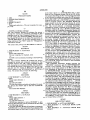
An input/output driver program residing in digital
{12,
27 Claims, 8 Drawing Figures
122
I2"
l
USER
l
USER
lUSER
TERM # I
TERM # 2
TERM# 0
L
i
ADAM
(FIG.2)
l
i
COMM
/'61
i
l
IO
/
L
COMM
/'62
i
COMM
LINK
LINK
LINK
DATA
PROCESSOR
DATA
PROCESSOR
DATA
PROCESSOR
#l
l4, _//
#2
[
I42 /'
# n
[4n
6
/' "
US. Patent Aug. 5, 1986
Sheet 1 of3
4,604,686
USER
USER
USER
TERM 1: I
TERM # 2
TERM# n
f
I
T
I
ADA M
(I-"IG.2)
/
coMM M's!
COMM
/’62
LINK
LINI<
LINK
DATA
PROCESSOR
DID-A
PROCESSOR
DATA
PROCESSOR
#I
,0
#2
I4, /
com
_
I42)
/'6"
# n
14,, /‘
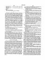
FIG. 2
( 2O
SCHEDUL ER
MoDuL E
30W
22\
MERGE/
FORMAT
MODULE
(24
USER
INTERFACE
MODULE
INFORMATION
COMMAND
INTERPRETER
MODULE
r 26
cOMMuN
ICATIONS
MODULE
—
DIRECTORY
Me
I
LOGGING
%
T0 USER #I
MODULE
m USER#rI
_/
26
TO PROC.#I
T0 PROC.#n
US Patent Aug. 5, 1986
Sheet2of3
4,604,686
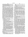
SCHEDULER
MODULE
FUNCTIONS
-
INITIALIZATN
MODULE
ROUTING
'
SCHEDULER
SERVICES
LOG
ERROR
HANDLING
R
usER
INTERFACE
MODULE
FUNCTIONS
.
SECURITY
MENU .
PROCESS G
usER
PROCESS'G
INPUT
LOG
cOMMArvD
INTERPRETER
MODULE
FUNCTIONS
APPLICATION
COMMAND
STREAM
LOG
ERROR
-
TERMINATN
ERROR
US. Patent Aug. 5,1986
Sheet3 of3
4,604,686
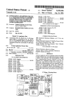
COMMAND
MODULE
FUNCTIONS
I/O
ENvIRON
READ
ENVIRON
WR' TE
wRITE
READ
ERROR
LOGGING
MODULE
FUNcTIONs
'
TI ME
/DATE
'
FORMAT
>
WRITE
MERGE/FORMAT
MODULE
FUNCTIONS
TEMP
STORE
CONSOLIDATE
OUTPUT
TYPE
LOG
1
4,604,686
2
data processors wherein the interface acts as a dumb
ASSOCIATIVE DATA ACCESS METHOD (ADAM)
AND ITS MEANS OF IMPLEMENTATION
accordingly, connects to the other processors as an
REFERENCED MATERIAL
with the accessed processor thinking it is a user at a
terminal requiring no communications protocols and
asychronous terminal which extracts data therefrom
terminal making the request for data.
Reference is made to an attached computer program
These and other objects are achieved in accordance
with a ?le driven computer program which resides in a
listing disclosed in micro?che form. Included are 2
micro?che containing a total of 179 frames.
computer apparatus using indexed sequential ?le struc
BACKGROUND OF THE INVENTION
1. Field of the Invention
The present invention relates generally to data re
trieval from data processors and more particularly to
the integration of data from data processors in a distrib
tures controlling the execution of one or more pro
grams. In this invention, a plurality of ?les are loaded
with information relating to interfaces utilized with
different processors, query languages, or data base man
15
uted processing environment.
In the present state of the art of data processors, there
is no known single machine which is able to take care of
agers as well as detailed item information as to data type
location and its method of retrieval. In response to a
user request, the ?les execute a plurality of programs or
instruction sets called modules which operate to logon
and query the required number of data processors of
all data processing needs. For example, a payroll may
be run on one machine, personnel requirements located
diverse vendor‘s types for speci?c information, extract
on another, and manufacturing and control inventory
located on still another, thereby yielding an abundance
and retrieve and read this information into a temporary
?le and thereafter reformat the received information
of information which is distributed in different ma
chines and in different formats. In order to make a busi
ness decision or update and cross reference information,
it becomes necessary to integrate this information in a
usable form. If one stays within a particular vendor’s
into a consolidated output in a predetermined user form
requested by the user such as terminal graphics or a
print out.
BRIEF DESCRIPTION OF THE DRAWINGS
While the present invention is de?ned in the claims
product line, the problem of data integration is allevi
ated somewhat since the same vendor normally will
annexed to and forming a part of this speci?cation, a
utilize the same type of data communications, protocols,
better
understanding of the invention can be had by
data base managers and query languages. A serious and 30
reference to the following description taken in conjunc
distinct problem exists, however, when one crosses
tion with the accompanying drawings in which:
outside a vendor’s boundaries. In such instances, one
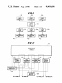
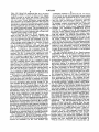
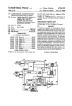
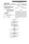
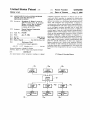
FIG. 1 is a block diagram generally illustrative of a
must normally emulate a bisynchronous batch protocol
communications system developed by IBM, for exam
ple, which requires human intervention, coordination
and integration of that information upon receipt. Ac
cordingly, where there are incompatible protocols, data
base managers and query languages, each differing in
capability and syntax, the problem of data integration
data communications system employing the subject
35
invention;
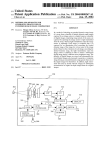
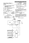
FIG. 2 is a block diagram illustrative of the computer
software utilized to implement the subject invention in
a digital computer;
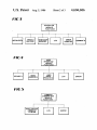
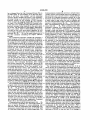
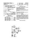
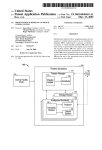
FIG. 3 is a block diagram illustrative of the functions
from diverse sources comprises a very primitive and 40 performed by the Scheduler module shown in FIG. 2;
FIG. 4 is a block diagram illustrative of the functions
performed by the User Interface module shown in FIG.
It is an object of the present invention, therefore, to
2;
provide an improvement in data communications in a
FIG. 5 is a block diagram illustrative of the functions
distributive processing environment.
It is another object of the invention to overcome 45 performed by the Command Interpreter module shown
in FIG. 2;
communications protocol limitations in integrating data
from a plurality of different data sources.
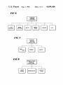
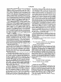
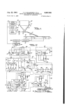
FIG. 6 is a block diagram illustrative of the functions
time consuming process.
It is still another object of the invention to provide for
the integration of data residing on different processors
for the purpose of management information capabilities.
performed by the Communications module shown in
FIG. 2;
It is a further object of the invention to provide an
intelligent interface between a user terminal and a plu
performed by the Logging module shown in FIG. 2;
and
rality of different types of data sources.
It is still a further object of the invention to provide
FIG. 8 is a functional block diagram illustrative of the
Merge and Format module shown in FIG. 2.
FIG. 7 is a block diagram illustrative of the functions
an interface between at least one user terminal and a 55
DETAILED DESCRIPTION OF INVENTION
The present invention is implemented in a digital
user terminal.
computer comprising a Hewlett-Packard 3000 series 44
Yet another object of the invention is to provide an
mini-computer which is structured to operate with a
interface between a user terminal and a plurality of 60 source programming language known as Pascal. Pascal
different data bases exhibiting different operational
is a programming language well known to those skilled
plurality of data bases with the interface functioning to
provide a dialogue with the data sources rather than the
characteristics and wherein the interface emulates an
asynchronous terminal to selectively access the data
bases in a prescribed fashion for that particular data base
and thereafter integrate information retrieved there
from.
Still yet another object of the invention is to provide
an intelligent interface between a user and a plurality of
in the art of computing science and was ?rst introduced
in 1971 by Niklaus Wirth. The standard reference on
Pascal is the text entitled, "Pascal User Manual And
65
Report“, by Kathleen Jensen and Niklaus Wirth,
Springer-Verlag,
New
York-—Heidelberg—Berlin,
1975. Another reference which may be resorted to for
an understanding of Pascal type programming is a text
3
4,604,686
4
entitled, “Pascal, An Introduction To Methodical Pro
such as data bases 141, 14g. . . 14,, each having different
gramming", W. Findlay and D. A. Watt, Computer
characteristics such as protocols, logons, data base man
agers, and query languages which sits on top of the data
base managers. Coupling between the various data
Science Press, 1978.
A program written in Pascal cannot be directly per
formed by the hardware of a computer. To make it
bases 141, 142 . . . 14,, is made by way of respective
executable, it must be translated from Pascal into an
equivalent set of machine code instructions and is ac
bi-directional communications links 16;, 162 . . . 16,,
complished by means of a compiler. Thus a computer
supporting Pascal codes interrelates with three pro
are well known devices for coupling data processors via
telephone lines. The ADAM interface 10, as will be
shown, operates as an asynchronous terminal and ap
grams, i.e. the translator program or compiler, the users
Pascal text or source program, and the equivalent ma
chine code or object program. A Pascal program, more
over, is run in two distinct stages. First the Pascal com
piler is brought into store and activated, whereupon it
reads the source program, checks it for errors and con
verts it into a corresponding object program. Secondly,
the object program generated from the ?rst stage can be
stored upon, for example, a magnetic disc. It is activated
which may comprise, for example, modems. Modems
pears to the various data bases 14;, 142. . . 14,, as one of
the user terminals 12;, 121 . . . 12,, to access the data
bases for speci?c information.
The ADAM interface 10 contains instructions which
are contained in a plurality of ?les called an Information
Directory 18 (FIG. 2), which are read and executed by
in turn and reads input, performs computation and
a number of programs which emulate the required dia
logues of the respective processors and data bases so
that the data needed can be retrieved, integrated, for
writes output in exactly the manner described by the
original Pascal program. Accordingly, all data pres
matted and outputted in the form of graphs, charts,
and/or reports speci?cally geared to the needs of the
user terminal making the request for information to the
ented to or taken from a computer is in the form of a
interface. Thus, each of the data bases 141, 142, 14,, is
text comprising a string of characters from some char
made to believe that it is in communication with a user,
acter set. The data comprising data which never
changes is modeled in a program as “constants” 25 but in reality it is in communication with the ADAM
interface 10. A user at one of the terminals 12;, 122 . . .
whereas data which changes is modeled in a program as
12,, simply makes a request to the interface 10 for spe
a “variable". A constant is created by a “declaration”
cific information which is to be presented in a predeter
while an instruction which alters the value of the vari
struction to read an item of data and store it in a variable
so that it can be subsequently used in some computation
mined form, whereupon the ADAM interface 10,
knowing where the speci?c information resides, sequen
tially or parallely couples to all the required data bases
is performed in Pascal notation by a “read statement",
while mimicking an asynchronous terminal and pro
while an output instruction to get results out of the
vides a dialogue to each processor and data base with
out human intervention to recover the data desired.
able is called an “assignment statement". An input in
computer is performed by a “write statement”. A com
plete Pascal program is a compilation of all the neces
sary de?nitions, declarations and statements. Moreover,
the Pascal program often includes sub-programs termed
functions and procedures. A function is specified in
Referring now to FIG. 2, there is shown in block
diagram form, software components of a Pascal pro
gram residing, for example, in a Hewlett-Packard 3000
series 44 mini-computer, not shown, including a plural
ity of input/output ports, also not shown, for establish
terms of a “function declaration” and constitutes a set of
instructions which takes one or more given values or 40 ing a signal transmitting connection between at least
absence thereof and returns a resultant value to be sub
one user terminal 12,-and at least one data base 14, via its
respective communications link 16,‘. The software com
sequently used. A procedure, on the other hand, is a set
ponents, called “modules", of the Pascal program in
of instructions in the form of a statement called a “pro
clude: a Scheduler 20, a User Interface 22, a Command
cedure statement” which merely commands a set of
45 Interpreter 24, a Communications module 26, a Log
operational steps that does not itself return a value.
ging module 28, and a Merge and Format module 30.
The present invention involves a well known concept
of ?le driven programming, meaning that a ?le controls
The Scheduler module 20 contains a “global statement”
which controls the operation of the remaining modules
the execution of a program. A ?le in Pascal notation
22 through 30. Before considering the functions of the
comprises sets of data read and written by programs and
which are of the same predetermined type. A number of 50 various modules, the Information Directory 18 will be
first considered.
different file structures are possible so that access to the
The Information Directory 18 comprises an indexed
speci?c data can be had by a series sequential access or
sequential ?le structure which is operable to develop a
direct access, depending upon the needs of the user. A
plurality of separate sets of instructions called ?les. The
?le is much like an ordinary variable in that it has an
?les of the Information Directory 18 contain the follow
identi?er and is declared in a "variable declaration”.
ing types of information: (a) user information compris
For a more detailed understanding of Pascal program
ing who the accessing user is, user passwords, the user
ming language, one is directed to the above noted refer
access capabilities, etc., data categories available to a
ence on the subject.
With the foregoing in mind, the present invention
comprises a computer program expressed, for example,
in Pascal notation, which resides in a computer adapted
to operate in accordance with Pascal type instruction
particular user, the language dialogue with a particular
60 user such as English, German, Spanish, etc. and being
tailored to the user’s requirements; (b) interface forma
tion comprising how to connect to the data bases such
as local area network access, autodial, etc., the particu
sets or codes under the control of a plurality of expand
lar logon information to the data bases where the data
able ?les. Referring now to FIG. 1, the subject inven
tion is depicted in block diagram form as an associative 65 resides, passwords and user identi?cation to logon in
order to access the data and processor logoff informa
data access method (ADAM) interface 10 which is
coupled between a plurality of user terminals 121, 122 .
tion; (c) data retrieval information comprising informa
. . 12,, and a plurality of diverse type data processors
tion on the structure of the data to be retrieved (IMS,
5
4,604,686
IMA, GE, ORACLE, sequential ?les, etc.), the query
language available to access the data and the require
ments to access or invoke and format a data FIND,
request for the query language; and (d) data manipula
tion and output format information comprising alge
braic equations to be applied against the data retrieved,
the manner in which to format data into a report format,
the manner to summarize the data, the manner to format
the data graphically and the manner to format the data
in a verbal format audio output. The Information Direc
tory 18 is adapted to maximum ?exibility in growth and
easy integration into new hardware and software tech
nologies as they appear on the market.
6
“command" variables) to perform the task. The Sched
uler performs the task, and immediately returns control
to the module that requested the service. The services
provided include: execute a system-level command,
open and close non-Information Directory ?les, pro
grammatically execute another program, display a sta
tus message, compare incoming data with "expected”
data (stored in the Condition File), and manipulate a
series of switches which control diagnostic (debug)
messages. The LOGGING INTERFACE function
executes the Logging module 28 sub-program based
upon the current logging requirements (minimum re
quirements comprise an ADAM user’s session begin’
ning and ending). The ERROR HANDLING com
The Information Directory 18, for example, com
prises six ?les. File No. 1 comprises a Security File 15 prises each error condition being detected and an ap
which contains the user name, password, the next mod
propriate message being displayed on the user’s termi
ule to be executed and the ?rst command to be exe
nal screen. Finally the TERMINATION function
cuted. File No. 2 comprises what is termed a Menu ?le
closes the ?les, performs any other miscellaneous termi
which contains screen images for a plurality of menus
nation tasks and terminates the program. The Scheduler
for the speci?c user terminals 121, 121. . . 12,, and which 20 module 20 is the only module continually executing in
may be respectively different, with each menu being
response to the Information Directory 18 during the
indicative of what can be obtained at each user terminal.
course of an operational phase. All the other modules 22
File No. 3 comprises a User Command Stream File
which contains the sequence of instructions to be fol
through 30 are executed individually as sub-programs
of the Scheduler program.
lowed when a speci?c menu request is made from a user 25
The User Interface module 22 is a Pascal program
responsible for all input and output to and from the user
terminal. File No. 4 comprises the Application Com
mand Stream File which contains the processes neces
terminals 121, 122. . . 12,,. Its functions typically involve
sary to complete a logical task. A “process” comprises
password validation of the password communicated
one or more instructions which when executed will
from a user terminal 12i, display of a primary menu
accomplish a logical task. File No. 5 comprises a Condi 30 (predetermined selected data type available to a particu
tion File containing entries which compare incoming
lar terminal) allowing a user to request a particular
data against expected data, compare an internally main
application, display of an application menu (subhead
tained counter to a value that is speci?ed in this ?le and
ings of data available to a particular terminal 12,-), trig
upon successful comparison, it dictates further process
gering a communications data capture process and out
ing by specifying the next module and command associ 35 put menu processing. As shown in FIG. 4, the User
ated with the particular comparison. And ?nally File
Interface module functions include a SECURITY func
No. 6 comprises a Graph ?le which contains the infor
tion which is indicative of the fact that the User Inter
mation needed for the generation of a predetermined
face module 22 accesses the Security File contained in
graphic output for the integrated data obtained.
Turning now to the modules of FIG. 2, the Scheduler
20 comprises a Pascal program or set of instructions
which performs the functions of opening and closing
the Information Directory ?les, miscellaneous initializa
the Information Directory 18, which contains valid
passwords for each user. The User Interface module 22,
upon accessing the Security File, validates the pass
word. Since the Security File in the Information Direc
tory 18 also contains the name of the ?rst command to
tion and termination tasks, provides storage for the
be executed (typically, “Display a Menu") upon valida
other modules 22 through 30 through a common link 45 tion, the MENU PROCESSING function of FIG. 4 is
age, executes the other modules based on the value
indicative that the User Interface module 22 accesses
outputted from the Information Directory, various ser
the Menu File in the Information Directory which con
vices required by other modules during execution, logs
tains screen images of the pertinent menus for a vali
dated user terminal 121. The User Command Stream ?le
the Scheduler module, and terminates execution of the 50 in the Information Directory 18 contains a sequence of
program upon completion of a user request. As shown
instructions for a given menu response. The User Inter
in FIG. 3, these functions can be categorized as INI
face module 22 additionally includes a USER INPUT
information, controls error conditions encountered in
TIALIZATION, MODULE ROUTING, SCHED
ULER SERVICES, LOG, ERROR HANDLING and
PROCESSING function shown in FIG. 4 which deter
mines the entry point into the Command Stream ?le in
TERMINATION. In the INITIALIZATION stage, SS response to a menu selection by the user at his user
all the ?les of the Information Directory 18 are opened.
terminal 121 . . . 12". The Command Stream ?le will be
Initialization of storage takes place, as well as any other
directly accessed using that response from the user
miscellaneous initialization tasks required including the
terminal as a key and entries will be serially processed
formatting of parameters of the Pascal code. Following
from that point, each triggering one of a given set of
this, the MODULE ROUTING function takes place 60 instructions such as “display another menu", "pass con
whereupon the User Interface 22, the Command Inter
trol to another module process", “capture communica
preter 24, the Communications 26, the Merge/Format
tions data” or “exit". After reading a record, the User
30 modules are executed based on a module parameter
Interface module 22 will interpret the “next module”
(PARM) formatted in the INITIALIZATION stage.
portion of the record. If the “next module” is the User
The SCHEDULER SERVICES function provides 65 Interface itself, it will execute the command and read
various capabilities to the other modules during execu
another record from the appropriate ?le (the command
tion. A service is performed when an executing module
executed may have instructed the User Interface to
requests the Scheduler (via the “next module” and
“bring up a menu”, in which case the current ?le will
7
4,604,686
have changed from the User Command Stream File to
the Menu File). If “next module” is not the User Inter
face, it will store “next module“ and the remaining
record in global variables and return to the Scheduler,
8
Communications module 26, moreover, includes input
/output routines which handle read/write requests to a
Interface module 22 also includes a LOG function,
which accesses the Logging module 30 at the appropri
data processor port and will receive various informa
tion from the Command Interpreter module 24 via the
Scheduler module 20 to determine such things as what
to read, when to read, when the read is complete and
the time tolerated before read is aborted. Physical con
ate times. The ERROR HANDLING function com
nection to a data processor 141, 142 . . . 14,, is shown in
allowing routing to the appropriate module. The User
prises each error condition being detected and an ap
FIG. I accomplished by means of respective communi
propriate message being displayed on the user's termi
cation links 161 . . . 16". These communications links
nal screen. The interaction of the MENU PROCESS
ING and USER INPUT PROCESSING functions
preferably comprise an autodial-modem connection;
provides the user with input/output capability as well
however, when desirable connection may be made
through a local area network (LAN) network. In the
as providing a graphics and report interface to the user
autodial-modem approach, the Application Command
terminals 121, 122 . . . 12,, via the input/output ports of
5 Stream ?le will contain the required phone numbers and
the mini computer containing the subject software
sorting sequence if "busy”, instructions necessary to
check for busy call pause and retry or abort conditions
if unsuccessful after a predetermined number of retries
and information to issue appropriate character to get
package.
The Command Interpreter module 24 comprises a
Pascal program which reads and expands the Applica
tion Command Stream ?le in the Information Directory
18 causing the other modules to perform speci?c tasks
via the Scheduler module 20. As evidenced by the block
diagram of FIG. 5, the Command Interpreter module 24
the attention of the particular data processor once a
modem, not shown, on the processor has answered. The
Communications module 26 will then issue a sequence
of statements to logon or logoff of the data processor
captured, de?ne the elementary commands necessary to
Stream ?le. The records accessed in the Application 25 logon to the processor in question, issue the code neces
sary for logon and issue the logoff statements and read
Command Stream ?le are grouped into “processes".
the logoff acknowledgment. Additionally, de?nitions
Each process consists of records which collectively
functions include accessing the Application Command
accomplish a task. Control structures built into the com
are generated as to what constitutes “data" and what is
mand language at the Information Directory ?les 18 can
cause execution of different processes, providing both
“PERFORM" and “GOTO” capability, meaning exe
“not data” and then establishes communication with the
correct query packages for the particular data processor
captured. This entails de?ning commands in the Infor
cute the process and return to the calling process, or
execute the process and do not return to the calling
mation Director 18 and the sequence of events which
are scheduled to comeback in the event of successful
process, respectively, as well as other necessary control
involution of the accessed data and includes the soft
structures. The Command Interpreter, after reading
each record, interprets the "next module” portion of the
record and determines which module should perform
the remaining instruction. If the “next module" is the
Command Interpreter itself, it will execute the com
ware necessary to communicate with the appropriate
data ports and the command sequence to initiate selec
tion of data from the accessed data processor.
The Communications module 26 acts ?rst of all as
mand and read another record. If “next module" is not
the Command Intpreter, it will store “next module" and
the remaining record in global variables and return to
put environment between itself and a particular data
processor 141, etc. This is shown in FIG. 6 by the block
entitled I/O ENVIRON. Data is stored in the Informa
tion Directory 18 which describes the communication
the Scheduler, allowing routing to the appropriate mod‘
shown in FIG. 6, to establish the prescribed input/out
environment which each data processor 141 . . . 14,, will
ule. This is evidenced by the block of FIG. 5 entitled,
APPLICATION COMMAND STREAM. Addition 45 use whereupon the Communications module 26 uses the
data to modify the ADAM interface 10 so that it can
ally, the processing of errors is performed by the Com
communicate properly with a particular data processor
mand Interpreter module 24 which are logged into the
14,-and to condition the input and ouput data. This data
log file by calling the Logging module 28 as evidenced
includes the ?le name, the parity and baud rate used, the
by the functional blocks ERROR and LOG of FIG. 5.
The Communications module 26 comprises a Pascal 50 terminal type, the end of record character, and a flag so
that the program will know whether to append a car
program which executes elementary commands to han
riage return character to the end of a transmission
dle communications with the multiple data processors
string. Also, the Communication module 26 functions to
14;, 142 . . . 14,, of FIG. 1 where the data requested by
generate the read environment indicated by the block
a user terminal 12, resides. The Communications mod
ule 26 makes the ADAM interface 10 appear as if it 55 READ ENVIRON of FIG. 6 to maintain and store the
data used by the READ routines. This includes the read
were the user terminal 12,-itself accessing the data pro
termination string information, the time i.e. number of
cessors. It controls and initiates input and output to the
seconds the READ command should wait for input
from a captured data processor before aborting and the
maximum number of “reads" to be executed before
aborting. Also included is the information required to
tary commands stored in the Application Command
store the input received by the captured data processr.
Stream ?le in the Information Directory 18.
Next a WRITE function is provided by the Communi
Communications with the data processors 14, . . . l4,7
cations module 26 which writes the text which is passed
to be accessed is preferably in a TTY mode which im
plies no special character or screen addressing type 65 to the port of the captured data processor. Next a
WRITE-READ function writes the text which is
characters need be interpreted, thus simplifying com
passed to a speci?ed port of the captured data processor
munications requirements since data can be dealt with
data processors 141, etc. by emulating an asynchronous
terminal to the data processors; however, the dialogue
with the data processors will be controlled by elemen
on a line basis rather than on a screen image basis. The
and posts a READ to that port and if no message is
4,604,686
received after a speci?ed time, an error is reported and
logged. If, however, a message is received, READ
TERMINATION condition is next tested. If it is met, a
normal exit is made from the Communications module
26. If a READ TERMINATION is not satis?ed, a test
is made to see if the input should be stored and if the
answer is in the af?rmative, the message is stored. If the
number of reads exceeds a maximum number speci?ed,
the module aborts further data retrieval. As in the case
10
the plurality of data processors where the data resides.
The information manager will also load the communica
tions information such as local area network (LAN)
access commands or autodial modem controlling com
mands. Logon information, user identi?cation on the
remote data processors and the passwords are also en
tered together with all information to retrieve remote
data such as information on how to invoke, for example,
RAMIS, how to access commands through RAMIS,
0 what is expected back as valid data, how long should it
take to get the data back from the remote processor,
format of data returning to the ADAM interface 10, etc.
of the Command Interpreter module 24, the Communi
cations module 26 also functions to provide Error Han
dling and logging to the Logging module 30 as evi
denced by the blocks ERROR and LOG of FIG. 6.
The Logging module 28 is a Pascal program which
performs, as is already evident, the functions of record
ing the status of the complete program's execution as it
progresses in a log ?le which is a key sequential access
(KSAM) ?le which contains records written in chrono
logical sequence by the Logging module which as
shown in FIG. 2, can be called by all other modules 20 20
Reformatting information is also entered which enables
the data retrieved to be displayed to the user in a prede
termined fashion. Additionally, information on how to
access different types of terminals is also entered by the
information manager such as how to format data for
through 30. The logging function is switch selectable
and may be displayed when desirable. As evidenced by
FIG. 7, functions to identify the user, the time and date
audio stations, different vendor’s terminals, different
vendor’s graphics terminals, etc. Once all this inform
aion has been loaded into the ?les of the Information
Directory of ADAM 10, the user is in a position to
retrieve speci?c data contained in diverse types of data
the module being logged and the writing of text into log
processors 14] . . . 14,,remotely located not only from
?le. These are shown by the blocks TIME/DATE, 25 the user terminal, but from each other.
The following dialogue is intended to illustrate the
FORMAT an WRITE.
interaction between a user at a user terminal 12,-, and the
Finally, the MERGE/FORMAT module 30 com
operations taking place with the ADAM interface 10,
prises a Pascal program executed by the Scheduler
hereinafter
referred to simply as ADAM, during a data
module 20 and functions in accordance with the TEMP
retrieval session.
STORE, CONSOLIDATE and OUTPUT TYPE
The user logs on to the ADAM interface through his
blocks to temporarily store the data retrieved from the
user terminal by entering:
accessed data processors 14} . . . 14,, via the Communi
cations module 26, consolidate the data retrieved in a
ADAM
common format, and output the data in a predetermined
The video display responds with screen displaying:
manner dictated by the user terminal through the Menu
?le and User Command Stream ?le contained in the
ADAM IS BEING INITIATED
Information Directory 18.
Thus ADAM 10 comprises a driver program whose
executing functions and data retrieval capabilities are
totally driven by the information in the Information
Directory 18 and all of the information in the Informa
tion Directory is logically connected to users‘ identity
through a pointer into the six various index sequential
?les, referred to earlier, which collectively make up the
Information Directory.
The following is intended to provide an overview of
the operation of the ADAM interface 10 and the man
ner in which it interacts with a user having access to a
user terminal 12,- and two different data processors 141
and 142, for example, respectively comprising a Hewl
ett-Packard (HP) located in one city and an IBM data
processor (IBM) located in another city. First of all, the
user who, for example, may be a ?nancial controller
identi?es global information requirements such as: over
ADAM proceeds afollows:
The Initiation Procedure starts whereupon the Sched
uler Module 20 clears the screen, opens all ?les of the
Information Directory (I.D.) 18, initiates COUNT,
COMMAND INTERPRETER and COMMUNICA
TION variables which are sent to the User Interface
Module 22 and sends a START mnemonic (identi?ca
45 tion of processing to be performed by a module) to the
User Interface Module 22. The Scheduler Module 20
loads the user's name into a global variable which is
accessible to the User Interface Module 22. The name is
used as a key into the Security File of the LD. The User
Interface Module 22 then prompts the user terminal for
a password.
The screen displays:
PLEASE ENTER PASSWORD:
The user responds with, for example:
head dollars, work in progress, contracts outstanding, 55
and contracts scheduled. He also de?nes speci?c infor
EVE
mation within these areas such as: department number,
badge number, labor rate, etc.
ADAM next does the following:
The user (?nancial controller) further provides his
The password is checked against the password in the
information requirements to an information manager
I.D. Security File. If the password is not valid, the user
who has the background and knowledge of where the
terminal is reprompted for the correct password. If the
data resides, what its format is, and now to access the
password is valid, the remaining contents of the Secu
data. This information manager, in response to the ?
rity File are used as the ?rst command that is passed to
nancial controller’s needs, then enters all of the follow
the Scheduler Module 20. In this example, the User
ing information into the six ?les of the Information 65 Interface Module 22 next prints a “Primary Menu",
Directory 18. He enters, among other things, a user
dialogue/menu for the user‘s customized terms that will
be used later by the user to access his information from
which is stored in the Menu File of the ID. 18.
The User terminal screen next presents a Primary
Menu display such as:
11
4,604,686
ADAM
PRIMARY MENU
1.
2.
3.
4.
5.
12
stores these values in a PARAMETER table. It then
looks to User Command Stream File of the LD. 18 for
instructions describing the ?ow of processing that needs
to be followed to emulate and access the HP processor
MIS
WORD PROCESSING
MAIL
REMOTE HOST
BYE
Please make selection:—-The user responds, for exam
for the data sought. Control is returned to the Scheduler
Module 20 which calls a COUNTER procedure which
resets a program counter. The Scheduler Module 20
returns control to the User Interface Module 22, which
reads the next record in the User Command Stream
File. This record indicates a Command Interpreter
command so control is returned to the Scheduler. The
Scheduler Module 20 using a MODULE ROUTING
ple, with:
“In
procedure calls the Command Interpreter Module 24.
ADAM accordingly continues:
The User Interface Module 22 evaluates the answer
through the entries and commands connected to that
The PROCESS mnemonic causes a HPWIPBUDGET
process to be executed to access the HP data processor.
response stored in User Command Stream File of the
ID. 18. Using a key mnemonic MENU, the User Inter
face Module 22 returns to the Menu File and prints an
stored in the Application Command Stream File of the
ID. Next alternating mnemonics direct the flow of
“ADAM MIS Menu” on the user terminal screen, it
being understood that “MIS" stands for “Management
Instructions for the HPWIPBUDGET process are
processing through different modules but always
20
through the MODULE ROUTING procedure in the
Scheduler Module 20. The Test Condition ?le in the
ID. is also called at appropriate times to check the
The screen then portrays the MIS MENU as follows:
progress of logging on, query, and data retrieval. When
retrieval is completed, the Scheduler Module 20 calls a
ADAM
25 XCOUNTER procedure which resets the program
MIS MENU
counter. The Command Interpreter module 24 reads
the last record in the HPWIPBUDGET process, and
1. WIP BUDGET vs. ACTUALS
recognizes that it should return to the User Interface
2. BYE
module 22. The User Interface, via the Scheduler mod
Please make selections:
30 ule 20, reads the next record in the Use Command
The user responds, for example, with:
Stream File. The record indicates that the Command
Interpreter module 24 should next be executed, so the
ADAM in turn continues processing in the following
User Interface module 22 returns control to the Sched
manner:
uler module 20, which routs control to the Command
The User Interface Module 22 evaluates the answer
through the entries and commands connected to that
Interpreter module 24.
The Command Interpreter module executes the
response stored in the I.D.’s User Command Stream
Information System".
File. Using the key mnemonic MENU, the User Inter
“PROCESS“ mnemonic, and the IBMWIPBUDGET
face Module 22 returns to the Menu File of the LD. and
asks the user for entries of MAN and CLASS OF
COST related to the WIP BUDGET vs. ACTUALS
menu. The screen then portrays the following:
process is next executed. This accesses the IBM data
processor in the same manner as the HP processor but
now emulating an IBM dial-up terminal. Instructions
for IBMWIPBUDGET are also stored in Application
ADAM
Command Stream of the ID. During processing of the
IBMWIPBUDGET process, the pertinent query files
MIS MENU
1. WIP BUDGET vs. ACTUALS
are activated and used for the data retrieval from the
45 IBM data processor. The Test Condition File is called
to check the progress of logging on and data retrieval.
The Test Condtion File will have speci?c instructions
2. BYE
Please make selection: 1
MAN:
CLASS OF COST:
for ADAM to follow (Retry loop, Quit, etc. . . , all with
appropriate error messages retrieved from the Applica
50
tion Command Stream File of the I.D.). After success
The user then enters a plurality of numbers, for exam
ful completion of the IBMWIPBUDGET process, the
ple, 203123 after MAN: and 01 after the CLASS OF
Scheduler
module 20 directs the ?ow of processing
COST:
through its Module Routing procedure to the User
The screen then displays:
ADAM
MIS MENU
1. WIP BUDGET vs. ACTUALS
2. BYE
Please make selection: 1
MAN: 203123
CLASS OF COST: O1
ADAM now operates to retrieve BUDGET vs. AC
TUALS data from the remote processors HP and IBM
in the following manner:
The User Interface Module 22 evaluates a mnemonic
PARMREAD (i.e. read parameters) As a result it reads
the terminal input for MAN and CLASS OF COST and
55
Interface module 22, which reads the next record in the
User Command Stream File of the LD. 18. A MENU
mnemonic causes the User Interface Module 22 to re
turn to the Menu File and portray “ADAM MIS OUT
PUT MENU” on the screen. The screen then displays
an Output Menu as follows:
ADAM
MIS OUTPUT MENU
1. WIP BUDGET vs. ACTUALS REPORT
2. WIP BUDGET vs. ACTUALS HOUR LINE
GRAPH
3. WIP BUDGET vs. ACTUALS HOUR BAR
CHART
4,604,686
13
4. WIP BUDGET vs. ACTUALS DOLLARS LINE
GRAPH
14
1. A method of integrating data in a distributed pro
cessing environment, comprising the steps of:
5. WIP BUDGET vs. ACTUALS DOLLARS BAR
CHART
(a) coupling at least one user terminal to a plurality of
mutually diverse type data processors through an
6. BYE
Please make selection:
intelligent interface;
(b) loading said interface with information for cou
pling to and retrieving data from each of said data
The user then responds with, for example:
processors;
“In
(0) operating said interface as an asynchronous termi
nal, thereby emulating a dumb terminal, in accor
dance with said information loaded therein and
Processing in ADAM then continues per the follow
ing: The User Interface Module evaluates the answer
and looks for instructions in the User Command Stream
File of the LD. The Scheduler Module 20 activates
selectively coupling to and accessing said data
processors for predetermined data via a communi
Command Interpreter Module 24 whereupon a PRO
CESS mnemonic calls upon the Merge/Format Module 15
cations link;
(d) retrieving and returning said predetermined data
30. The Merge/Format Module reformats the data re
trieved from both the HP and IBM data processors by
(e) integrating said data retrieved from said plurality
writing out a new ?le in a new format. This includes
of mutually diverse type data processors at said
to said interface via said communications link;
consolidating multiple input records into one output
record. After successful completion of the merging 20
procedure the Scheduler Module 20 executes a CRE
ATE mnemonic. The Scheduler calls a XCREATE
procedure and programmatically runs a program that
interface comprising the steps of consolidating the
data received from said diverse type processors
and reformatting the data into a common format
following said consolidating step; and
(f) reporting said data thus integrated to said user
prepares a report using data formatted by Merge/For
terminal in a user friendly form.
mat Module 32. All other procedures within ADAM 25
2. The method of claim 1 and further including the
are suspended and the report is written on the user
steps of:
terminal screen. When desirable, it can be printed out in
(g) loading said interface with menu information re
text form on a printer, or in graphic format on a termi~
nal or plotter.
lating to the types of data selectively available to
said user terminal;
.
A STATUS mnemonic next prompts the Scheduler 30
Module 20 to display a message.
The Screen next displays a command:
HIT SPACE BAR FOR NEXT MENU OR SAY BYE
The user then typically responds by entering “BYE” 35
on his user terminal.
(h) displaying said menu information; and
(i) entering menu related requests at said user termi
nal, and
wherein said reporting step (0 comprises the step of
reporting data retrieved in accordance with said
menu request.
3. The method of claim 2 wherein said step (h) of
The User Command Stream File of the LD. 18 instructs
displaying comprises the step of displaying said menu
the Scheduler Module 20 to pass control to the User
Interface Module 22. The User Interface Module gener
ates a CLEAR mnemonic and clears the user terminal
information on a user terminal screen.
screen. An EXIT mnemonic causes a NEXIT proce
ted data on said user terminal screen.
4. The method of claim 3 and wherein said step (t) of
reporting said data comprises displaying the reformat
dure in the Scheduler Module 20 to execute. The
5. The method of claim 3 and wherein said step (f) of
ADAM session will terminate with the logging module
28 being advised, the Information Directory ?les are
reporting said data comprises the step of printing out
closed, and “END OF PROGRAM” is commanded to 45
be portrayed on the screen. The screen then displays:
END OF PROGRAM
Thus what has been shown and described is an intelli
gent software interface acting as a dumb terminal re
quiring no communications protocol and which is able
to atomatically connect to diverse type data processors
as an asynchronous terminal and extract data therefrom,
with the processor “thinking” it is a user at a terminal
making the request, and accordingly can access differ
ent data processors such as data bases for certain infor
mation contained therein, retrieve and integrate the
information and reformat it into a composite ?le and
display it to the user in a manner requested without
human intervention.
While there has been shown and described what is at
present considered to be a preferred embodiment of the
subject invention, it is to be noted that the same has
been made by way of illustration and not limitation.
said reformatted data in a predetermined copy form.
6. The method of claim 2 wherein said intelligent
interface comprises a file driven program residing in
digital computer apparatus and wherein said informa
tion for coupling to and retrieving data from said data
processors as well as said menu information is located in
a plurality of data ?les, said program further executing
a plurality of instructional sets in response to said infor
mation loaded into said ?les.
7. The method of claim 6 wherein said plurality of
instructional sets comprise a plurality of Pascal type
55 modules controlled by said ?les.
8. The method of claim 7 wherein one of said modules
termed a Scheduler module executes all other of said
modules.
9. The method of claim 8 wherein said other modules
include at least a User Interface module which controls
all inputs and outputs to and from said user terminal, a
Command Interpreter module which causes said other
modules to perform speci?c tasks via the Scheduler
module, a Communications module which emulates
Accordingly, all modi?ctions, alterations and substitu 65 asynchnous terminal communications between each of
tions may be made without departing from the spirit and
said data processors and said interface, and a Merge/
scope of the invention as set forth in the appended
claims.
Format module which operates to temporarily store the
data retrieved from said data processors via the Com
15
4,604,686
16
terminal; and said apparatus additionally com
munications module, consolidate the data retrieved in a
common format and output the data to said user termi
nal via said User Interface module.
10. The method of claim 9 and wherein said modules
additionally include an Error Handling function which
prises:
(c) means for displaying said menu information; and
(d) means for entering menu related requests at said
use terminal.
17. The apparatus of claim 16 wherein said reporting
means (vi) comprises means for reporting data retrieved
operates to translate any communications error into a
user format.
in accordance with said menu request.
18. The apparatus of claim 16 wherein said means (c)
for displaying comprises a user terminal screen.
11. The method of claim 9 wherein said modules
additionally include a Logging module for recording
the status of the program’s execution as it progresses.
19. The apparatus of claim 18 wherein said means (vi)
12. The method of claim 6 wherein said information
for reporting said data comprises means for coupling
loaded into said data ?les includes: (i) user information
the reformatted data to said user terminal screen for
comprising the identity of the accessing user, user pass
display.
words, user access capabilities, data categories available
20. The apparatus of claim 18 wherein said means (vi)
to a particular user and the language dialogue for a 5
for reporting said data comprises means for printing out
particular user; (ii) interface information comprising the
said reformatted data in a predetermined copy form.
manner in which connection to said data processors can
21. The apparatus of claim 16 wherein said intelligent
be made and including local area network access, auto
interface comprises a ?le driven program residing in
matic telephone dialing, the particular logon informa
digital computer apparatus and wherein said informa
tion to said data processors where said predetermined
tion for emulating, coupling to and retrieving data from
data resides, the passwords and user identi?cation to
said data processors as well as said menu information is
logon in order to access the data and processor logoff
located in a plurality of data ?les, and said means (ii)
information; (iii) data retrieval information comprising
information on the structure of the data to be retrieved, 25 through (vi) comprises a plurality of instructional sets
executed in response to said information loaded into
the query language available to access the data and the
said ?les.
requirements to access or invoke and format a request
for data, and the speci?c query language; and (iv) data
manipulation and output format information comprising
functions to be applied against the data retrieved, the
manner in which to format the data into report format,
the manner to summarize the data, and the manner to
22. The apparatus of claim 21 wherein said plurality
of instructional sets comprise a plurality of Pascal type
30
modules'controlled by said ?les.
23. The apparatus of claim 22 wherein one of said
modules termed a Scheduler module executes all other
of said modules.
24. The apparatus of claim 23 wherein said other
processing environment and comprising:
35 modules at least comprise a User Interface module
which controls all inputs and outputs to and from said
(a) at least one user terminal adapted to interact with
user terminal; a Command Interpreter module which
a data processor;
causes said other modules to perform speci?c tasks via
(b) a plurality of data processors;
the Scheduler module; a Communications module
(c) an intelligent interface coupled between said user
terminal and said plurality of data processors, said 40 which emulates asynchronous terminal communications
between each of said data processors and said interface;
intelligent interface further comprising:
and a Merge/Format module which operates to tempo
(i) means containing information for emulating and
rarily store the data retrieved from said data processors
coupling to and retrieving data from each of said
via the Communications module, consolidate the data
data processors;
(ii) means for operating said interface as an asynchro 45 retrieved in a common format and output the data to
said user terminal via said User Interface module.
nous terminal in accordance with said information;
format the data.
13. Apparatus for integrating data in a distributed
said data processors for predetermined data via a
25. The apparatus of claim 24 wherein said modules
additionally comprise an Error Handling function
respective communications link;
which operates to translate any communications error
(iii) means for selectively coupling to and accessing
(iv) means for retrieving and returning said predeter
mined data from said data processors to said inter
face via said respective communications links;
into a user format.
26. The apparatus of claim 24 wherein said modules
additionally comprise a Logging module for recording
the status of the program’s execution as it progresses.
(v) means for integrating said data retrieved from said
27. The apparatus of claim 23 wherein said ?les are
plurality of data processors at said interface; and
(vi) means for reporting said data thus integrated to 55 located in an Information Directory and comprise:
(l) a ?rst ?le termed a Security File which contains
said user terminal in a user friendly form.
the user name, password, the next module to be
14. The apparatus of claim 13 wherein said plurality
executed by said Scheduler module and the ?rst
of data processors are comprised of mutually diverse
command to be executed by said next module;
type data processors.
(2) a second ?le termed a Menu File which contains
15. The apparatus of claim 14 wherein said integrat
a plurality of screen images for a plurality of menus
ing means (v) comprises means for consolidating the
for said user terminal and wherein each menu is
data retrieved from said diverse type processors and
indicative of the type of data which can be ob
means for reformatting the retrieved data into a com
tained at said us terminal;
mon format.
(3) a third ?le termed a User Command Stream File,
16. The apparatus of claim 15 wherein said intelligent 65
which contains the sequence of instructions to be
interface further includes:
followed when a specific menu request is made
(vii) means containing menu information relating to
from a user terminal;
the types of data selectively available to said user
17
4,604,686
18
(4) a fourth ?le termed I116 Application Command
upon successful comparison dictates the process by
Stream File which contains a plurality of processes
which execute the instructions necessary to com
the next module and command associated with a
plete a logical task‘
(5) a ?fth ?le termed a Condition File which contains 5
emries which compares incoming data against ex_
pectcd dam, compares an internally maintained
particular comparison;
(61 a sixth ?le termed a Graph File wh_lch comams the
information needed for the generation of a graphic
output format for the integrated data retrieved.
counter to a value that is speci?ed in the file, and
*
15
25
35
40
45
55
65
"
*
‘
"