1
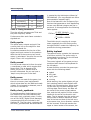
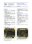
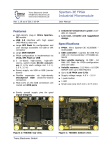
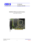
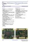
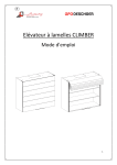
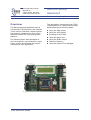
Trenz Electronic GmbH Brendel 20 32257 Bünde, Germany www.trenz-electronic.de Retrocomputing Baseboard Rev 0.9 as of 2004-11-10 First Steps: Ping Pong Demo Overview This application note describes an FPGA implementation of a simple tennis game, demonstrating the following tasks: The Retrocomputing Baseboard carries the Spartan-3 Micromodule, and extends it with various interfaces, display options and memory expansions to form a fullyfeatured System-On-Chip development platform. The following demo was developed to give the engineer a quick hands-on experience, and to demonstrate the board’s features and their application. Using the VGA output Using the LCD Display Encoding of PS/2 data Using the game port Using the Audio output Testing of Memory Using the Digital Clock Manager Figure 1: Baseboard with Micromodule Trenz Electronic GmbH 1 Retrocomputing Startup To use this demo you have to do the following steps: 1 Plug the Micromodule onto the Baseboard and connect all necessary peripherals like monitor, keyboard and speaker 2 Establish a JTAG connection to the host system by using either the low cost JTAG Programmer from Trenz Electronic, or any other 2.5V JTAG chain capable JTAG interface 3 Supply the baseboard with power by either using the USB port, or by connecting a 5V supply to the DC-jack 4 Run the programming tool iMPACT, which is included in WebPACK ISE, on your host system 5 Select boundary scan mode and use the autoconfiguration, finally it should show two objects: the FPGA and the Flash 6 Assign a configuration file to the device you want to program 6.1 for the FPGA: toplevel.bit 6.2 for the flash: toplevel.mcs 7 Finally power cycle the board, or press the program button if you have a module revision >=01 Note: If you configured the flash, you have to disconnect the JTAG cable before you can configure the FPGA from Flash. Architectural Description Ping Pong is a simple tennis game which everybody knows from the early computer gaming age. It is played twosome, so you have to connect two keyboards, or one keyboard on J12 and a joystick on the game port. The arrow keys move the player around and the keypad zero key releases the ball. For additional acoustic effects a speaker can be attached on Audio out (J3). Trenz Electronic GmbH Figure 2 visualizes the design hierarchy. toplevel lcd ps2 sprite timing1024x384 sound sram clock_synthesis Figure 2: Design hierarchy Entity lcd The entity lcd initialize the LCD-display and makes simple write commands available. The display is connected for 4-bit mode, so all commands and data bytes have to be split into two nibbles. The processing time takes 40µs for normal commands (see the display manual for more details), so a clock signal with a higher period has to be generated outside the entity to trigger the state-machine. Another clock for creating the enable-signal is needed, half as long as the other clock period. For initializing the display, several settings and waiting times have to be executed: 1 Wait for min. 40ms after power on 2 Set 8-bit mode 3 Wait for min. 4.1ms 4 Set 8-bit mode 5 Wait for min. 100µs 6 Set 8-bit mode 7 Set 4-bit mode 8 Set 4-Bit mode, display lines and dots 9 Display, cursor, blinking character on 10 Clear display 11 Wait for clear time (min. 1.64ms) 12 Set direction of cursor movement 2 Retrocomputing The outgoing ready line signaled that the entity is up to write symbols on the display. If the write signal goes high, the incoming data byte will be downloaded to the lcd. Entity ps2 This entity processes the ps/2 keyboard protocol. If a key is pressed the keyboard sends the make code. When releasing, it sends the break code. While pressing the key a longer timer, the make code is send periodically. With this method you can detect, if several keys are used at the same time. Key Make code Break code kp 8 (UP) 75 F0, 75 kp 2 (DOWN) 72 F0, 72 kp 4 (LEFT) 6B F0, 6B kp 6 (RIGHT) 74 F0, 74 kp 0 70 F0, 70 space 29 F0, 29 ed that contains the coordinates for the current pixel. The frame begins in the upper left corner of the screen and is build up line by line to all up 1024 x 384 Pixel, but the origin of the coordinates is in the lower right corner. The synchronization pulses are negative polarized, so the monitor works in 480 line mode. Around the screen there is are blank area that has to be considered by generating the synchronization pulses. Figure 3 illustrate the timing parameters for the horizontal synchronization and Figure 4 them of the vertical synchronization. 1024 Pixel RGB hsync B C E D A Figure 3: Horizontal refresh cycle 384 lines line Table 1: Scan-Code Values in hex The entity does not provide any parity control or evaluation of the whole sending code, it only separates between make and break code and assigns the transmitted byte to the associated signal in the following way: If there occur a falling edge at the incoming ps2 clock signal, a shift register takes up the bit from the ps2 data input. When the startbit reaches the end of the register the recorded code byte is compared with the make code of the keys that we need in our design and an output is generated. If a break code identifier (F0) has been received earlier, no signal will be outputted. Entity timing1024x384 This entity generates the timing information for the whole gaming operation. There are two counters (x,y) implement- Trenz Electronic GmbH hsync G H I F J Figure 4: Vertical refresh cycle Table 2 shows the counter values needed for generating the synchronization. The counter for the horizontal direction is triggered by the system clock. After 1295 cycles the counter for the vertical deflection is triggered. Description Counts Time A horizontal refresh 1295 32,4µs B horizontal image 1024 25,6µs C left blanking 83 2,07µs D right blanking 32 0,8 E hsync width 156 3,9µs F vertical refresh 428 13,9ms 3 Retrocomputing Description Counts Time G vertical image 384 12,4ms H top blanking 32 1,0ms I bottom blanking 10 324µs J vsync width 2 64,8µs Table 2: Timing Parameters ly created by the Architecture Wizard of ISE WebPack. (For more Details see Xilinx documentation xapp462.pdf.) One of the features is the Frequency Synthesizer that generates a clock depending on two user-defined integers and the input clock. In this application the following ratios applies: CLKFX_Multiply ⋅ClkIn CLKFX_Divide 4 = ⋅30MHz=40MHz 3 Thus the refresh rate amounts 72Hz and the pixel frequency 40MHz. ClkOut= Furthermore after each frame a strobe is signaled out. Entity sprite The sprite entity outputs a signal if the current pixel lies on the object for that the sprite stands for. The 40MHz clock is used by all components, especially the VGA timing entity timing1024x384 needs this frequency to provide the timing parameters. It contains constants for the size of the object and input vectors for the position. With the aid of the current pixel coordinates, it calculates if the pixel lies on the object. Then a hit is signaled out. Entity toplevel Entity sound The control signals of the game port are combined with these of the keyboard for the left player. For the sound output a bit from the pixel y-coordinate is used, which toggles with about 6kHz. This is passed to the Audio_out pin for 7 frames when a bounce is detected. So you can hear a 'beep' every time you hit the ball. Entity sram The SRAM is not used for the game, but there is a memory test implemented which writes data into the RAM and reads it back. If a mismatch is detected, one of the LED's is turned off. Entity clock_synthesis To provide another clock frequency than the 30MHz from the USB interface chip the entity clock_synthesis exists. It uses one of four DCM ( Digital Clock Manager) components which are included in the Spartan-III. The files clock_synthesis.vhd and clock_synthesis.xaw are automatical- Trenz Electronic GmbH The toplevel entity contains the instances of all other entities. The sprite entity is instantiated three times: for the left and the right bat, and the ball. A state-machine controls the game operation with the following states: splash left_start right_start running While starting, the sprite objects will get their starting position and the ball additionally his course direction. When pressing the zero key the state changes into running state. Each frame, the bats will be moved if the control signals advise that, and the ball position will be recalculated with the aid of the direction variables. The hit signals from the sprite entities provide for bounce detection: does that of the bat and that of the ball occur at the same time, the x-direction variable will be inverted. If the ball reaches the upper or lower border of the screen, the 4 Retrocomputing y-direction variable will be inverted. If the ball leaves the left or right border of the screen, the game is restarted. Also the hit signals are used to adjust the rgb color output to display the objects on the monitor. Project files The project files for this application note are provided in WebPACK ISE format with all synthesis options set up to achieve a push button flow. Furthermore, the resulting .mcs file to program the Flash PROM and a .bit file to program the FPGA via JTAG are provided. References Spartan-3 FPGA Micromodule User's Manual Trenz Electronic July 9, 2004 Retrocomputing Baseboard User's Manual Trenz Electronic October 20, 2004 History Rev. Date Who Description 0.9 2004-11-10 TS created Table 3: History Trenz Electronic GmbH 5