1
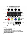
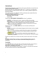
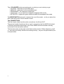
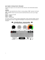
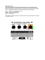
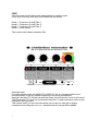
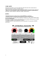
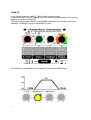
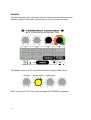
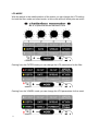
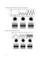
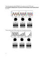
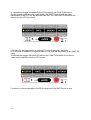
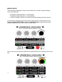
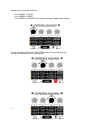
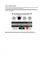
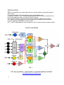
M.r.l. Chatterbox Resonator
User Manual
Mad Rooster Lab
User manual
Rev. 1.0
CBR-2
QUICK START
FEATURES
- 100% Analog audio path and filters design
- 2 modes: Filter with LP-BP-HP and Vowel mode
- Built-in LFO for self-modulation
- Digital controlled matrix with led indication for easy control
- CV controlled Resonance, global modulation, + 1 CV for each filter
- CPU controlled filters in vowel mode, for an exact vocal tuning
- Vowel mode with 3 CV modulation: Vocal Morphing, From-to, and Random
- Linear transition between LP and HP with switch for BP
- Standard Eurorack format and power
2
THE MODULE
The Chatterbox Resonator is a full analog audio path multimode and vowel filter with
a digital microprocessor controller.
So the audio path is fully analog hand made with T.H. Technology, the digital side
has only the duty to control the filter modes , and is used to generate a digital LFO
and store programs.
The module consists of 3 12dB self oscillating multimode state variable filters that
can work in different combinations.
The filter can switch between two main modes:
• Multimode filter/ resonator
• Vowel Filter
The first mode MULTIMODE / RESONATOR involves 3 combination:
• UNISON : the 3 filters work in serial , creating a 36dB multimode filter
• Master/Slave : the 3 filters work in parallel , as 3 resonator with 12dB/oct slope
with the first set as master frequency and the others as slaves filters.
• FREE : the 3 filters work indipendently in parallel, as the previous mode but
without any link between the filters.
The second mode , the VOWEL MODE acts as an evolved vocal filter with 3
combinations
• MORPH : the vowel can be manually changed and the formant can be morphed
thru CV control
• From – To : allow to set the two vowels that set the range for the modulation ,
than , thru cv control the filter will move between these two “points” as an
indicized modulation.
• RANDOM (RND) : allow to set the two vowels that set the range for the
modulation , as in the previous mode, but in this case the cv will scroll random
beteen the two “points”.
The filter can switch from one mode to the other via the control switch in the matrix.
LFO
We added a digital LFO as a duty lfo, to make modulations without using CV
modulators or to get easily into complex modulations adding the duty lfo to cv
modulators.
The KNOBS
The 4 BLACK knobs on the upper side are 3 Encoder Controllers, each of them is
associated to a particular function depending on the filter mode selected.
The function is indicated on the panel.
They work as a hook/relative value encoder , so when you turn the knob it will hook
the value and then will act as a classic potentiometer.
3
The 4 COLOURED knobs are analog pots, so what you see is what you get.
• IN LEVEL : attenuator for the audio input
• MOD LEV : attenuator for the modulation input
• RESONANCE : the resonance control pot
• Green Knob : let you fade from lowpass to highpass filter mode
• BP SWITCH : bypass the green knob and select the bandpass filter mode.
The MODE SWITCH just switch between the row of the matrix , so let you select the
filter mode and jump in the lfo section control.
The CONNECTIONS
The first couple of jack are the audio connections, the IN and OUT.
The second couple of jacks are the cv mod in connectors, the first MOD IN is linked
to different parameter depending on the Filter MODE while the second is directly
connected to the resonance amount.
The last three jacks on the right in the black section are the 3 filters frequency cutoff
cv , and they are directly linked to the analog circuitry , they are not processed by the
microprocessor.
4
MULTIMODE / RESONATOR FILTER MODE
Selecting the upper row in the matrix the filter will work in the multimode/resonator
mode.
UNISON
This filter mode stacks the three filters in unison getting a 36dB resonant multimode
filter.
In the UNISON mode only the first and the last black knobs are active (see image
below).
Knob 1 : Frequency Cutoff
Knob 2 : inactive
Knob 3 : inactive
Knob 4 : mode switch
the unison mode is useful for classic purposes like a steep resonant lowpass filter to
get deep bass sounds, an aggressive bandpass for sequences and lead sounds for
example...
5
MASTER / SLAVE
The master mode let the three filters work in parallel mode , the first filter set the
master cutoff frequency (knob1) the other filters cutoff controls (knobs2&3) set the
distances between the master freq (filter1) and the other two cutoff frequencies (filter
2 & 3 ), making the first cutoff “move” the three filters with a fixed relation.
Knob 1 : Frequency Cutoff Master Filter (1)
Knob 2 : Frequency Cutoff Filter 2
Knob 3 : Frequency Cutoff Filter 3
Knob 4 : mode switch
This mode is useful to get complex multimode resonating sounds that can be tracked
by keyboard control.
6
FREE
The free mode let the filters work indipendently in parallel mode.
Every filter works by itself and is not linked with the others.
Knob 1 : Frequency Cutoff Filter 1
Knob 2 : Frequency Cutoff Filter 2
Knob 3 : Frequency Cutoff Filter 3
Knob 4 : mode switch
This mode is the classic resonator filter .
Important note:
In multimode/resonator the MOD LEV & MOD CV IN are not processed by the
microprocessor to get an ultrafast response to incoming modulations.
However the three CV IN that controls the filters freq are directly linked to the circuit.
The Resonance CV input has a particular behaviour, it adds resonance value to the
resonance set by the pot.
This means that if you turn the resonance pot to max you can get an higher
resonance level using the res cv in , because the two values will be added.
7
VOWEL MODE
Selecting the bottom row in the matrix the filter will work in the vowel mode, a
powerful mode for creating vocal-like sound.
The Vowel mode works well using the Bandpass Mode and mid to high resonance
values (5-10), this setting is useful to bring the filters' interaction to generate the
harmonic content useful to create the classic vowel sound.
MORPH
The first submode of vowel mode is called MORPH or morphing;
In MORPH mode all the black pots are active except the second one.
In this mode you can make linear transitions between a vowel and the other using
the first potentiometer.
Using the FORMANT pot you can shape the vocal formants allowing you to imitate
the voice of a children or an adult for example.
In MORPH MODE both the MOD IN and the internal LFO control the VOWEL1
parameter.
8
FROM-TO
In the second submode called FT all the black pots are active;
In this mode you can quickly switch from one vowel to another using a CV incoming
signal or using the internal LFO.
The first two pot called VOWEL1 and VOWEL2 select the two vowels used for the
transition, FORMANT act as in the MORPH mode.
The transition is controlled by an incoming CV signal thru MOD IN pot.
9
RANDOM
The last submode as the name say, act as a casual transition between all the
different vowels; in this mode only the last two pot to the right are active.
The random factor is a CV controlled parameter using the MOD IN pot.
Note: The internal LFO in this mode modulate the FORMANT parameter.
10
LFO MODE
With the switch in the middle position of the matrix you can change the LFO setting
for both the filter mode and vowel mode; in this mode all the 4 black pots are active.
Coming from the FILTER mode you can change the LFO parameters for the filter.
Coming from the VOWEL mode you can change the LFO parameters for the vowel.
11
The first parameter DEPTH control the LFO amplitude.
RATE control the speed of the LFO
12
The third parameter called SPREAD is only active in the FILTER mode;
in this mode the phase of each LFO can be shifted to obtain some interesting effects,
but remember, this parameter is only active in FILTER mode! (vowel mode use only
one LFO)
The last parameter ATTACK control the LFO amplitude over time.
13
Is it possible to trigger momentarily the LFO pressing the FUNCTION button,
this will work in both filter and vowel mode; the DEPTH rate and all the other
parameters of the LFO can be selected from the LFO, the FUNCTION button will
simply turn the LFO on and off.
LFO can also be triggered by an external CV signal going thru MOD IN.
LFO will turn on whenever a signal of about 1V or over will be present at the MOD IN
input.
To activate the trigger with MOD IN hold on the FUNCTION button from filter or
vowel mode and then switch to LFO mode.
For return to normal operation of MOD IN simply turn the DEPTH pot to zero.
14
MEMORY MODE
The Chatterbox Resonator has an useful feature for recreate complex settings.
It can save and load :
• 3 patches containing filters + its lfo settings
• 3 patches containing vowel + its lfo settings
• 1 patch containg a combi of the filters and vowel settings with their own lfo.
To access this function to save/load a filter setting switch to filter/resonator than
Press and Hold FUNCTION and turn the (black) knob 4 to select the memory
location respectively from filter mode or vowel mode.
As you can see the memory locations are represented by the 3 blinking leds on the
left.
15
Chose the one you like and than :
• turn KNOB 1 to LOAD
• turn KNOB 2 to SAVE
• turn KNOB 3 to CANCEL (exit without saving or loading any setting)
for store a setup hold on the FUNCTION button and turn the save pot;
saving is confirmed by the 3 blinking leds.
16
DEFAULT MEMORY MODE
CBR-2 contains two default memories that are loaded at the start-up, these contains
the matrix parameters and the LFO parameters.
To update these parameters hold the function button and rotate the second pot to
save the new setting; this will store the updated parameters whether you are in filter
mode or vowel mode.
Note: Is only possible to save setting of the black pots, LEVEL IN, MOD IN,
RESONANCE, and FILTER MODE can't be stored as they are analog controls.
17
INSTALLATION
CBR-2 is designed to be used within the euro format modular synthesizer system
(Euro-rack);
For more info about this format please go to: www.doepfer.com
It requires 100mA of +12/-12 using the standard 8X2 flat connector, where the red
line is the negative voltage -12 (see the picture below).
To install the module in your Euro-rack system requires 18HP (9cm) of space.
M.r.l. decline any responsibility for harm to persons or apparatus caused by an
incorrect operation/installation of this module.
M.r.l. is NOT responsible for harm caused by a DIY enclosure and/or power solution.
BLOCK DIAGRAM
For any question, comments or request please contact:
[email protected]
18
TIPS AND TRICKS
- Increase the resonance level through CV. Resonance level can be increased
beyond the value of the potentiometer using a CV signal in the appropriate input
(RES CV); in this way it is possible to obtain higher levels of resonance up to selfoscillation, creating interesting effects or becoming an oscillator!!
19