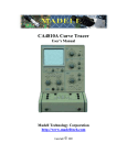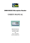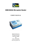
1
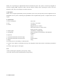
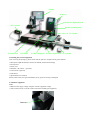
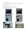
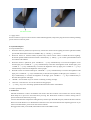
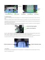
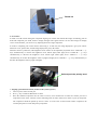
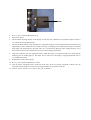
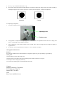
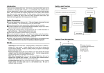
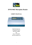
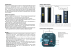
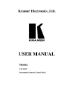
MADELL
QK-PL 2005
BGA Precision Placement System
User’s Manual
2005
Thank you for purchasing our QK-PL2005 Precision Placement System. The system is exclusively designed for
accurately aligning SMD component. Please read this manual carefully before operating the system. Store this
manual in a safe, easily accessible place for future reference.
1. Description
Thank you for using the QK-PL2005 precision placement system. The system provides precision alignment for the
QK-IR2005 rework system. Combining the QK-IR2005 with the QK-PL2005 provides a complete BGA rework
system.
2. Specifications
1. Power consumption:
about 15W
2. Fuse:
1A (110V), 0.5A (220V
3. Camera:
12V/300mA
Magnification: 22×10times
Horizontal resolution is 480 TV lines
Signal type PAL composite
4. Vacuum pump:
12V/600mA, 0.05Mpa (Max)
5. LED lighting:
White LED down and red LED up with adjustable
brightness
6. Keyboard:
8 keys
7. Upward and downward movement range:
93mm
8. Upward and downward movement motor:
24VDC/100mA
9. Weight:
22Kg
10. Vacuum pencil is controlled by on and off switch
11. Camera on PL and IR is controlled by telescopic arm. Brightness of IR camera will be controlled by keyboard of
PL.
12. Camera output signal is video signal
Note:
* When purchasing the equipment, please specify voltage.
* The video camera has been calibrated before leaving factory.
3. Product Picture
Display
PL-HEAD
Component alignment knob
RPC camera
Nozzle controlling knob
PL Camera
PL baseboard
PCB fixture
PL Micro-alignment PL Micro-alignment 2 PL keyboard
4 Checking the received equipment
After receiving the packages, please check if all the parts are complete and in good condition.
* Main parts of QK-PL2005 (PL camera, PL-HEAD, Vacuum and housing)
* PL keyboard
* Power cord
* RPC2005—IR camera
(optional)
* LCD monitor (optional)
* PCB fixture
* QK-PL2005 user’s manual
Please contact with your agent immediately if any parts are missing or damaged.
5. Install the equipment
Note:
* Make sure the supply voltage complies with the equipment voltage.
* Take out the setscrew on the PL camera arm before installing the equipment.
Setscrew
5.1 Placing the QK-IR2005 system
There are four mounting points on the left side of the QK-PL2005. Place the QK-IR2005 rework system on the left
side of the QK-PL2005, and align the four support pins with the four locating points on the QK-PL2005.
5.2 Assembling the QK-PL2005
1.
Put the plug of display into the display connection socket behind equipment.
2.
Put the plug of IR camera into its camera socket and its video socket.
3.
Put the plug of PL camera into its camera socket and its video socket.
Please refer to the following picture.
HEAD power
output
Power output
IR camera
video socket
PL camera
video socket
Display socket
Power socket
Power switch
PL keyboard socket
IR camera socket
Pl camera socket
IR camera socket
5.3 Apply Power
Put the connector of power cord into Power socket behind equipment, and put the plug into three-terminal grounding
power socket to switch on power.
6. keyboard and parts
6.1 keyboard functions
1.
When PL camera is pulled out, keyboard only controls PL camera and its lighting. PL-head’s (placement head)
upward and downward movement is forbidden. Key “↑” and key “↓” are useless.
2.
When PL camera is retracted inside, keyboard only controls reflow camera of BGA-IR and its lighting.
PL-head’s upward and downward movement is allowed. Key “↑” and key “↓” can control upward and downward
movements of PL-HEAD.
3.
When PL camera is pulled out, press “LIGHT B” + “↑” keys simultaneously to increase the brightness of PL
bottom light; press “LIGHT B” + “↓” keys simultaneously to decrease the brightness of PL bottom light; press
“LIGHT T” + “↑” keys simultaneously to increase the brightness of PL top light; press “LIGHT T” + “↓” keys
simultaneously to decrease the brightness of PL top light.
4.
When PL camera is retracted inside press “LIGHT B” + “↑” keys simultaneously to increase the brightness of IR
light; press “LIGHT B” + “↓” keys simultaneously to decrease the brightness of IR light; press “LIGHT T” + “↑”
keys simultaneously to increase the brightness of IR light; press “LIGHT T” + “↓” keys simultaneously to
decrease the brightness of IR light.
5.
“ZOOM+” and “ZOOM-“ keys are used for controlling zooming of image.
6.
“FOCUS+” and “FOCUS-“ are for the camera focusing purpose.
7.
“↑” and “↓” key is for controlling upward and downward movement of PL-HEAD.
6.2 Other Operational Parts
1. PCB fixture
Movable PCB fixture is able to fix different size PCB. It has three locknuts. Two locknuts are used for locking
PCB clamp bar to prevent it from unnecessary moving. The third fixture locknut is used for locking orbit to
prevent fixture from unnecessary moving.
Unscrew PCB locknuts and push the sliding block by hand to open the PCB clamp bar, make the distance between
them accord with PCB size. Fix PCB between them and screw down PCB locknut after adjusting position. If you
want to lock PCB fixture, please screw down fixture locknut.
We suggest that when you fix PCB, make PCB be fixed in the middle of orbit.
Navigation
Sliding
Block
Insert PCB from here
Fixture locknut
PCB locknut
PCB clamp bar
PCB locknut
2. Adjustment knobs
There are two adjustment knobs on PL-HEAD, one is component aligning knob, and the other is nozzle controlling
knob.
Turn nozzle controlling knob to make the vacuum nozzle move up and down. As soon as the vacuum nozzle touches
component, the vacuum pump starts to work and pick up component. Turn it clockwise for up movement and turn it
anticlockwise for down movement.
Turn component aligning knob to make nozzle turn, and change the position of component to realize the alignment
purpose. Direction of turning knob accords with nozzle turning.
Component aligning knob
Nozzle controlling knob
Turn “PL Micro-adjustment knob1 to make PCB fixture move right and left for adjusting PCB’s right and left
position. Turn it clockwise for rightwards move and turn it anticlockwise for leftwards move.
Turn “PL Micro-adjustment knob2 to make PCB fixture move forward and backward for adjusting PCB’s front and
rear position. Turn it clockwise for forward move and turn it anticlockwise for move backward.
PL Micro-adjustment knob
PL Micro-adjustment knob
3. IR Camera
IR camera position can be adjusted. First, unscrew thumb nut in corresponding direction and then adjust. IR camera
can move up and down or turn.
Thumb nut
4. PL Camera
It needs to use IR camera during the component aligning. PL camera will transmit the image of soldering point on
PCB and component pins under nozzle to display through video signal and user can see these images on display
screen. At the moment, you can use every adjusting function to align component.
It needs to completely pull out PL camera when using it. At this time, the image displayed is got by PL camera.
When not in use, push it back, and the image displayed is got by IR camera.
When PL camera is pulled out, LED brightness of PL camera can be adjusted by keyboard. Press “LIGHT B” + “↑”
keys simultaneously to increase the brightness of PL bottom light (white light); Press “LIGHT B” + “↓” keys
simultaneously to decrease the brightness of PL bottom light (white light); Press “LIGHT T” + “↑” keys
simultaneously to increase the brightness of PL top light (red light); Press “LIGHT T” + “↓” keys simultaneously to
decrease the brightness of PL top light (red light).
Pull and push the pole by hand
7. Aligning operation Instructions (Switch on the system’s power)
1.
Turn on power switch of each part.
2.
Press “↓” key to make PL-HEAD move down.
3.
Place the soldered component into the center of salver, move PCB fixture to make the vacuum pen aim at
component on the salver. Turn the nozzle controlling knob to make nozzle move down to pick up component.
The component should be picked up from its center. As soon as the vacuum nozzle touches component, the
vacuum pump starts to work and pick up component.
Salver
4.
Press “↑” key to make PL-HEAD move up.
5.
Pull out PL camera.
6.
Check whether the image display on the display accords with user’s demand. Use keyboard to adjust it. Refer to
“6.1 instruction of keyboard function”.
7.
Unscrew the PCB locknuts on the PCB fixture to open PCB clamp bar. Fix the soldered PCB on PCB fixture and
adjust PCB’s position. Make the screen display the image of soldering point, and make the images of soldering
point image and component have the same center. It is convenient for adjusting. After roughly adjusting, screw
down fixture locknut to lock PCB fixture to prevent it from sliding right and left.
8.
Align the component with four adjustment knobs. Make the images of component solder pins image and the
soldering point on PCB superpose. The image can be observed on the display. Aligning adjustment refer to
“6.2.2 adjustment knobs”.
9.
Push back PL camera after aligning.
10. Press “↓” key to make PL-HEAD move down.
11. Turn the nozzle controlling knob to make the nozzle move down for placing component on PCB. Once the
component touches PCB, the vacuum stop working and make the component is placed.
12. Unscrew fixture locknut, move PCB to the part of IR2005 t
5.
Press “↑” key to make PL-HEAD move up.
6.
Pull out PL camera and adjust the image display by keyboard. Observe the images: if the two images (round) on
the display superpose, the system is precise. If not, the system is imprecise, it needs to be adjusted.
Imprecise
Precise
9.2 Adjusting the alignment
1.
Unscrew the fixation screw of the camera box on both sides.
Adjusting screw
Fixation screw
2.
Using spanner to adjust the two adjusting screws on fixed screws, the adjustment extent can’t be too large, until
the two round images on the display superpose.
3.
After superposing, screw down fixation screws on both sides. After screwing down, the image of display is
superposed too.
4.
If necessary, you can repeat the above steps (9.1~9.2) to calibrate once again.
10. Equipment Maintenance
Remark:
For ensuring reliable function and maintenance of equipment, please use parts provided by original factory.
Clean parts:
Clean the dust on system with clean towel.
Clean the prism of PL camera with optical cleaning tissues and be careful not to scrape it.
Add oiling in axletree and gear periodically.
Use a towel with cleaning oil to clean PCB fixture and orbit.
Contact:
Madell Technology Corporation
7372 Walnut Ave. Suite V
Buena Park, CA 90620
USA
http://www.madelltech.com