1
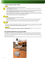
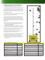
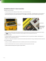
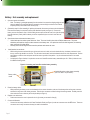
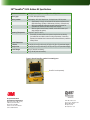
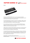
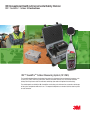
3M Occupational Health & Environmental Safety Division
3M™ SoundPro™ Outdoor Kit Instructions
3M™ SoundProTM Outdoor Measuring System (SP-OMS)
The SoundPro Outdoor Measuring System helps protect the instrument from environmental exposure, such
as wind, rain, snow, chemicals, particulates, animals, vandalism and theft. It is also used for extended
battery life with up to one week of continuous monitoring (two weeks with optional second battery).
The weatherproof case holds the 3MTM SoundProTM and battery pack with room for accessories and storage
of the system components while not in use. The exposed components are made of stainless steel or plastic
to resist corrosion.
Dangers, Warnings, Cautions & Battery
Danger!
Failure to observe the following procedures may result in serious personal injury
•
Risk of Electrical Shock. Avoid nearby overhead wires and electrical fixtures. The conductive electrical mast will tend to attract stray voltages and
currents, including the possibility of Lightning.
•
Risk of Fire or Explosion. Do Not connect to AC power while the lid is sealed or closed. Do Not connect to AC power while the lid is sealed or closed.
Do Not modify the enclosure to provide AC power from an external sources while the lid is closed. Hydrogen gas may be released from the lead-acid
batteries during charging leading to a risk of explosion. The cover must be left open during the re-charge process.
•
Risk of Chemical Burn. Although the batteries provided are Absorbent Glass Mat (AGM) Sealed Lead-Acid (SLA) batteries that can be stored, transported, operated, and re-charged in any orientation, there is still a slight risk of being exposed to sulfuric acid if the case is cracked or punctured. These
batteries can be shipped as “dry cargo” and do not require special hazardous material shipping.
•
Not for use in explosive or hazardous locations. This product is not intrinsically safe.
Warning!
Failure to observe the following procedures could damage the instrument:
•
•
•
Read the manual before operation.
Do not operate in temperatures exceeding 50°C (122°F). Excessively hot and extreme sun exposure may lead to over-heating. Use additional sun
shields to reduce running temperature, if necessary. Repeated or extended time in extreme environments will lead to premature battery failure.
Substitution of components may impair the accuracy of the instrument. Repair should be performed by authorized service personnel only.
Caution!
General
Before first use, insure that the voltage select switch on the charger is set to the line voltage in your location. It may be set to either nominal 115V or 230VAC.
Battery cycle life is preserved by storing the batteries fully charged. Turn OFF the power at the power distribution panel when not in use. Fully charge the
batteries as soon as possible after any use and before storing them for long periods of time.
Intended Use
The SoundPro Outdoor measurement system is intended to provide protection to re-chargeable batteries for extended outdoor operation of the SoundPro.
Consult your company’s safety professional for local standards, or call 3M at 1-800-243-4630 with questions.
3M™ SoundPro Outdoor Measuring System (SP-OMS)
How it works? The weatherproof case provides a stable base for mounting the microphone mast. There is an internal battery monitor
circuit to reduce the risk of damaging the batteries by over-discharge. The circuit also protects against over-voltage, over-temperature
(70°C or 158°F), and over-current (2 Amps, each output). There is an on-board universal input battery charger that fully re-charges empty
batteries in about 16 hours or less.
Provisions in the case design allow customer-supplied padlocks and cables to be used to lock the case and secure it to a stationary object.
Page 2 Assemble the outdoor kit: Field Instructions
• To assemble the outdoor kit refer to Figure 1 and Table 1.
1. Mounting the outdoor microphone and mast to the weatherproof case.
a. Assemble the mast pieces by screwing the threaded coupler of the
shaft segment with coupler of item 3 (see Figure/Table) , to the threaded
base shaft (see 2). Multiple extensions (see 3) may be used to increase
the height of the microphone.
b. From inside the case (see 1), feed the smaller female end of the cable
assembly (9) through the hole in the case cover.
c. For easier insertion, you may lubricate the connector boot with a bit
of petroleum jelly. Feed the female end of the cable through the mast,
and then completely through the preamp adapter (see 4). The insertion
tool (see 11) will be necessary to push the connector through the preamp
adapter (see 4).
d. Assemble the preamp adapter (see 4) to the mast. Then assemble
the mast to the case by screwing the threaded portions together.
• Caution: do not over tighten.
e. Screw the microphone (see 6) onto the preamp (see 5). Connect the
preamp to the female end of the cable by properly orienting and inserting
the connector into the preamp. Hold the cable connector while turning
the knurled knob on the preamp to tighten the connectors.
f. Grasp the preamp and push the connector’s rubber boot into the
preamp adapter until the preamp is completely seated.
g. Insert the windscreen (see 7) inside of the bird spikes (see 8). Place
this assembly over the microphone preamp. Gently spread the bird
spike wires and insert them into the holes on the preamp adapter.
• Note: Please be cautious when bending the wires to prevent them
from deforming.
Table 1: SoundProTM Outdoor kit parts
1. Weatherproof case assembly.
Part #: 057-832
10. Case plug w/ 059-330 O-ring (both parts required) .
Part #: 056-467
2. Base Shaft with sealed nut. (1.0 m; 39”)
Part #: 056-472
11. Cable insertion tool.
Part #: 056-475
3. Shaft segment with coupler. (1.4m ;56”). Two
provided for optional extra height. (1.9 m; 73”)
Part #: 056-473
12. SoundPro® outdoor 12V power cable assembly.
Part #: 057-241
4. Preamp adapter 2 inch/5 cm tall.
Part #: 056-462
13. SoundPro®outdoor battery assembly (1 or 2) provided.
Part #: 057-242
Part #: 053-809
14. SoundPro® outdoor power distribution panel.
Part #: 057-826
6. Microphone (various models included with SoundPro and
identified in Appendix A of user manual)
(See Part # on
delievery note.)
15. Universal Input (Switch-able) 12V/5A Battery Charger.
Part #: 053-562
16. USA 115V IEC320 Line cord #18AWG.
Part #: 068-028
7. Windscreen/weather shield.
(Part #: 056-463)
8. Bird Spikes.
(Part #: 056-464)
17. European 230V IEC320 Line cord #18AWG (Optional).
Part #: 054-462
9. SoundPro® outdoor extension cable assembly.
(Part #: 057-240)
18. Desiccant SG-40 Rechargeable canister.
Part #: 057-235
5. SoundPro
SoundPro).
TM
Page 3
Preamp assembly (included with
Assemble the outdoor kit: internal connections
2) Making the internal connections
a) Connect the other end of the cable (see 9 in Figure 1/Table 1 ) to the meter inside the case.
b) For brief runtimes (4 hours or less), you may use the internal battery power of the SoundPro®. For extended runtime, connect the internal 12Volt power cable (see Figure 2) to the meter at its bottom inlet. Then turn On the power switch at the power distribution panel (see Figure 3).
Figure 2: Connecting the battery power
Figure 3: On/Off switch for the SoundPro Outdoor Kit
Power cord
connected
On/Off switch
Power distribution
panel (see 16 in
Table 1 for part
details)
c) When you have turned On the power switch and the SoundPro, verify that the power cord is connected for external power. (Note: the battery
icon,
, will appear on the display of the SoundPro as a fully charged icon when connected with AC power cord.)
3) Make the measurements.
a) Follow the SoundPro user manual to prepare and run your measurements. (Note: this may require a pre-calibration, setup changes, and
pressing the run key or programming an auto-run.)
b) When you are ready, place the SoundPro in the pocket of the case and verify the SoundPro is running on external power and close up the case.
4) Turn-off and disassemble.
a) When you are finished, turn Off the SoundPro and then turn Off the power switch at the power distribution panel.
b) Remove and disassemble the mast, microphone, and windscreen and place the parts back into the case.
c) Remove and store the case plug with o-ring (see 10 in Figure 1/Table 1).
Page 4
Battery: first assembly and replacement
1. Open and unpack the batteries.
• Note: The battery is packaged separately from the outdoor kit to ensure the shipping weight of each
carton is under the 70-pound limit which is imposed by common freight carriers such as Federal
Express (FEDEX) and United Parcel Service (UPS).
2. (Please skip step 2 for first assembly.) If replacing the batteries, disconnect and remove the old batteries.
Disconnect the battery’s connectors from the power distribution panel (see Figure 3). Remove the
battery cover as discussed in Step 3. While holding the case open, stand the case on its right side (away
from the wheel end). Gently slide the battery out of the compartment (one at a time if more than one
battery).
3. Open the enclosure and remove the battery cover.
• Unlatch and open the outdoor system enclosure. Note: The cover is held in place with six Phillips-Head screws. The power
distribution panel and the charger are also mounted on the battery cover. It is optional to remove the shaft segments, the accessory
parts, and some of the foam layers.
• Carefully remove the six larger screws around the perimeter and remove the cover.
4.
Install batteries into enclosure.
• While holding the outer enclosure lid open, tip the entire case on its side, so that the wheel-side is up, the battery enclosure is near
the top, and the right handle is on the floor. This will make it much easier to slide the batteries down into their compartments. Position
each battery so that the wires and posts can still be seen as you slide it into position. Lay the enclosure back down in its normal
orientation.
• As displayed in Figure 4 below, it is optional to connect two SoundPro outdoor battery assemblies (see 13 in Table 1) inside the case
for additional battery power.
Figure 4: Connecting two SoundPro outdoor battery assembly
Battery cables
routed
Installed Soundpro outdoor battery assembly
(see 13 in Table 1 for part details)
5. Route the battery cables.
• While positioning the battery cover over the batteries in the correct orientation, take one of the battery wires and its green connector,
and feed it through one of the rubber grommets. Take the other connector and feed it through the other grommet. Carefully route the
wires under the cover so that they will not be pinched (see Figure 4)
6. Replace cover and screws.
• Position and secure the cover in place with the six (6) screws you removed in Step (3).
7. Connect the Batteries.
• Connect the two battery cables into the Power Distribution Panel (see Figure 4) at the two connectors near the RED fuses. These two
connectors are the only connectors that may be used for the batteries.
Page 5
Maintenance and Care instructions
Recharging the internal batteries
1. Open the case and leave it open for the duration of the charging. See the WARNING: “Risk of FIRE or EXPLOSION” above. Keeping
the case open also allows the charger to stay cool.
2.
You may leave the master On/Off switch in either position. If you leave the master On, you may also leave the meter connected, but
doing that will increase the charging time by about 10%.
3. Before the first use of the charger, verify that the input voltage selector on the charger module is set to the appropriate line voltage. The
selector is a small red slide switch near the power inlet that is moved into the correct position using a small screwdriver. In the USA, it is
115 Volts (the UP position). With the European cord you will use 230 Volts (the Down position). When it is in it’s proper location, you will
see your line voltage displayed.
4.
Connect your line cord to the charger power inlet.
5.
Connect the cord to a power outlet.
6. There is a status lamp on the charger which is located on the opposite end from the power inlet. The lamp has three states.
•
Yellow: Indicates Charging.
•
Green: Indicates Finished Charging.
•
Blinking: Indicates Charging Problem.
7. Leave the power cord connected until you see the GREEN (FINISHED) indicator. The charging rate is 5 Amps. In the unlikely event that
the batteries (84 Amp-Hours) are completely emptied (more than eight days of discharge), it will take at least 84AH /5 A = 16.8 Hours
(overnight), to completely re-charge them. For each hour of charging, you should be able to get about 10 hours of runtime.
8. At 80% depth of discharge, the batteries should be good for at least 200 cycles. The batteries will age and lose capacity over time, and
will likely need to be replaced about three to five years from purchase.
9. When charging has completed you may unplug the charger and store the cable away. The enclosure lid can safely be closed as soon as
the charger is unplugged.
Reactivating the desiccant
When you first use the silica gel canister in the area to be protected, it may become saturated rather quickly as it "drinks up" residual
moisture. Once the residual dampness is removed, you can maintain a dry condition with less frequent need to reactivate the silica
gel. Reactivation times below are minimums. Sometimes, when the silica gel becomes overly saturated, it's good practice to extend the
reactivation period. However, do not vary from the recommended temperatures.
When the blue silica gel beneath the inspection window turns pink, reactivate as follows:
•
Place the unit in a vented 150°C (300°F) oven for at least 3 hours. (Or until the silica gel turns blue again). Note: The desiccant can be
reactivated as many times as you want to.
Storage Recommendations
The batteries have an extremely low self-discharge rate, thus providing extended storage capability while maintaining high state-ofcharge levels for dependable operation. These batteries have a shelf life more than two times that of conventional lead batteries. To
assure maximum reliability, we recommend that all stored batteries be recharged (boost charged) at least every 12 months or when the
open circuit voltage drops to 12.00 volts per battery, whichever occurs earlier. The batteries should be checked more frequently if storage
temperature regularly exceeds 25°C (77°F).
The outdoor measurement system should be stored in a cool dry location with the lid closed whenever possible. High battery storage
temperatures will lead to excessive self-discharge and premature battery failure.
Page 6
3MTM SoundProTM SE/DL Outdoor Kit Specifications
Windscreen Attenuation
0.5dB @ 2kHz, 1dB @ 6kHz, 1.4dB @ 10kHz, 2dB @ 20kHz
Battery type
(1) 12 Volt, 42 Amp-Hour battery
Battery runtime
Total capacity : 80% of 42 Amp-Hours , 34 Amp-Hours of 12 Volt power
•
Approximately 3.5 days, with nominal 400 mA load and de-rated to 80%
depth of discharge (3.5days x 24Hours/day x 0.4Amp = 34 Amp-Hours)
•
Operating Temperature
Overall Dimensions
In Transit
Ready to Use
Overall Weight:
When other additional accessories are used, reduced runtimes are
calculated from the 80% de-rated 34 Amp-Hour Capacity.
• With the optional second battery installed, runtime will increase up to 7
days (doubling the runtime).
0°C to 50°C (32°F to 122°F)
• Excessively hot and extreme sun exposure may lead to over-heating.
Use additional sun shields to reduce running temperature, if necessary.
Repeated or extended time in extreme environments will lead to premature
battery failure.
64 cm (W) x 51 cm (D) x 38 cm (H); 25” (W) x 20” (D) x 15” (maximum Height)
64 cm (W) x 51 cm (D) x 200 cm (H); 25” (W) x 20” (D) x 78” (maximum Height)
30 kg; 67 lbs (with one battery)
45 kg; 100 lbs (with two batteries)
Figure 5: Sample SoundPro outdoor kit assembly parts
SoundPro is sold separately
Occupational Health &
Environmental Safety Division
Quest Technologies, a 3M company
1060 Corporate Center Drive
Oconomowoc, WI 53066
Customer Service: 262-567-9157
Toll Free: 800-245-0779
www.3M.com/detection
Please recycle. Printed in USA.
© 2012 3M Company
All rights reserved.
057-829, Rev.C. 8/12