1
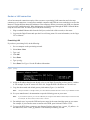
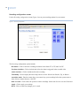
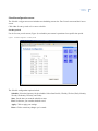
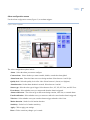
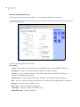
Digia Browser
User Manual
g
Copyright
Copyright © 2007 GE Security. All rights reserved.
This document may not be copied in whole or in part or otherwise reproduced without prior
written consent from GE Security except where specifically permitted under US and
international copyright law.
Document number: 1058008B (May 2007).
Disclaimer
The information in this document is subject to change without notice. GE Security (“GE”)
assumes no responsibility for inaccuracies or omissions and specifically disclaims any liabilities,
losses, or risks, personal or otherwise, incurred as a consequence, directly or indirectly, of the
use or application of any of the contents of this document. For the latest documentation,
contact your local supplier or visit us online at www.gesecurity.com.
This publication may contain examples of screen captures and reports used in daily operations.
Examples may include fictitious names of individuals and companies. Any similarity to names
and addresses of actual businesses or persons is entirely coincidental.
Trademarks and patents
GE and the GE monogram are registered trademarks of General Electric Company.
Digia Browser product and logo are registered trademarks of GE Security.
Other trade names used in this document may be trademarks or registered trademarks of the
manufacturers or vendors of the respective products.
Software license agreement
Important: This end-user license agreement (“Agreement”) is a legal agreement between GE
and You. Read the following terms and conditions carefully before installing or using this
Software. This agreement provides a license from GE to use the Software. It also contains
warranty information, disclaimers, and liability limitations. Installing and/or using the Software
confirms Your agreement to be bound by these terms and conditions. If You do not agree with
these terms and conditions, do not install or use the Software or, if already installed,
immediately cease all use of the Software and promptly uninstall all components of the
Software.
1. Definitions. The following definitions apply to this document:
a. “GE”, with respect to title to or warranty of the Software, means GE Security Inc., a Delaware corporation.
b. “Software” means the executable software or firmware programs and accompanying
documentation installed on the GE products, plus any upgrades, modified versions,
updates, additions, and copies of the software furnished to Customer during the term of
the license granted herein.
c. “Documentation” means all associated media, printed materials, and electronic documentation accompanying the Software.
d. “Licensed Product” means the Software and Documentation.
e. “Customer” means the person or organization, or parent or subsidiary thereof, who uses
the Software for its intended purposes, and excludes distributors, authorized resellers,
value-added resellers and original equipment manufacturers. Customer may be
referred to as You or Your, whether an individual or a business entity of any kind.
f. “Machine” means the computer, workstation, terminal, or other hardware product on
which the Software is installed.
2. License. All rights to and in the Licensed Product, including, but not limited to, copyrights,
patents, trademarks, and trade secrets, belong to GE, and GE retains title to each copy of the
Software. You agree that GE at any time, upon reasonable notice, may audit Your use of the
Software for compliance with the terms and conditions of this Agreement. Subject to the
terms and conditions of this Agreement, GE grants You a nonexclusive license to use the
Software, but only in the country where acquired, provided that You agree to the following:
You may:
a. install and use the Software on a single Machine at one time, unless You have purchased
additional copies of the Software, in which case You may install the software on the
number of Machines for which You have purchased copies of the Software;
b. use the original copy of the Software provided to You for backup purposes.
iii
You may not:
a. transfer or distribute the Licensed Product to others, in electronic format or otherwise, and
this Agreement shall automatically terminate in the event of such a transfer or distribution;
b. use the Software over a computer network;
c. sell, rent, lease, or sublicense the Software;
d. copy or modify the Licensed Product for any purpose, including for backup purposes.
3. Term. This Agreement is effective until terminated. You may terminate this Agreement by
uninstalling all components of the Software from all Machines and returning the Software to
GE. GE may terminate this Agreement if You breach any of these terms and conditions.
Upon termination of this Agreement for any reason, You agree to uninstall all components of
the Software and return the Licensed Product to GE. All provisions of this Agreement relating
to (i) disclaimer of warranties; (ii) limitations on liability, remedies, and damages; and (iii) GE’s
proprietary rights, shall survive termination of this Agreement.
4. Object code. The Software is delivered in object code only. You may not alter, merge,
modify, adapt, or translate the Software, nor decompile, disassemble, reverse-engineer, or
otherwise reduce the Software to a human-perceivable form, nor create derivative works or
programs based on the Software.
5. Limited warranty. GE warrants that for one (1) year from the date of delivery of the
Licensed Product (Software Warranty Period), the functions contained in the Software will be
fit for their intended purpose as described in the applicable Documentation from GE, and will
conform in all material respects to the specifications stated in such Documentation. GE
does not warrant that the operation of the Software will be uninterrupted or error-free. GE
does warrant that the media on which the Software is furnished will be free from defects in
materials and workmanship under normal use for a period of thirty (30) days from the date
of delivery (Media Warranty Period). Except as specifically provided therein, any other
software and any hardware furnished with or accompanying the Software is not warranted
by GE.
Your exclusive remedy under this limited warranty for nonconforming Software shall be
repair or replacement of the Software, at the sole discretion of GE. To obtain a repair or
replacement of nonconforming Software, contact GE Customer Service toll-free at 888GESECURity or online at www.gesecurity.com during the Software Warranty Period.
Except as expressly provided above, the licensed product is provided “as is” without
warranty of any kind, either expressed or implied, including, but not limited to, implied
warranties of merchantability or fitness for a particular purpose and, except as expressly
provided above, You assume the entire risk as to the quality and performance of the licensed
product.
6. Limitation of liability. GE’s sole obligation or liability under this agreement is the repair or
replacement of nonconforming software and/or defective media according to the limited
warranty above. In no event will GE be liable for damages, whether consequential,
incidental, or indirect, nor for loss of data, loss of profits, or lost savings, arising from use or
inability to use the software or documentation (or any hardware furnished with the
software), even if GE has been advised of the possibility of such damages, nor for any claim
by any third party.
7. General. Any materials provided to You by GE shall not be exported or reexported in
violation of any export provisions of the USA or any other applicable jurisdiction. Any
attempt to sublicense, assign, or transfer any of the rights, duties, or obligations hereunder
shall be void. This Agreement shall be governed by and interpreted under the laws of the
State of New York, United States of America, without regard to conflicts of law provisions.
You hereby consent to the exclusive jurisdiction of the state and federal courts located in
Multnomah County, Oregon, to resolve any disputes arising under or in connection with this
Agreement, with venue in Portland, Oregon.
iv
Digia Browser
User Manual
8. Restricted rights legend. The Licensed Product is provided with RESTRICTED RIGHTS. In
the event the United States Government or an agency thereof is granted a license, the
following additional terms apply: Restricted Computer Software, as defined in the
Commercial Computer Software–Restricted Rights clause at Federal Acquisition Regulations
52.227-19, and the restrictions as provided in subparagraphs (c)(1) and (c)(2) thereof; and as
applicable, the Government’s rights to use, modify, reproduce, release, perform, display, or
disclose the Software also are restricted as provided by paragraphs (b)(2) and (b)(3) of the
Rights in Noncommercial Technical Data and Computer Software–Small Business Innovative
Research (SBIR) Program clause at DFARS 252.227-7018.
9. Acknowledgment. You acknowledge that You have read and understand this agreement
and agree to be bound by its terms. You further agree that this agreement is the complete
and exclusive statement of the agreement between You and GE, and supersedes any
proposal or prior agreement, oral or written, and any other communication relating to the
subject matter of this agreement.
Intended use
Use this product only for the purpose it was designed for; refer to the data sheet and user
documentation. For the latest product information, contact your local supplier or visit us online
at www.gesecurity.com.
FCC compliance
This equipment has been tested and found to comply with the limits for a Class A digital device,
pursuant to part 15 of the FCC rules. These limits are designed to provide reasonable protection
against harmful interference when the equipment is operated in a commercial environment.
This equipment generates, uses, and can radiate radio frequency energy and, if not installed
and used in accordance with the instruction manual, may cause harmful interference to radio
communications.
Changes or modifications not expressly approved by the party responsible for compliance
could void the user’s authority to operate the equipment.
EMC directive
The European Union directive on electromagnetic compatibility (2004/108/EC) requires nonEuropean manufacturers to designate an authorized representative in the Community.
Our European representative is GE Security, Kelvinstraat 7, 6003 DH Weert, Nederland.
The European directive Waste Electrical and Electronic Equipment (WEEE) aims to minimize the
impact of electrical and electronic equipment waste on the environment and human health. For
proper treatment, recovery, and recycling, return the equipment marked with this symbol to
your local supplier upon the purchase of equivalent new equipment, or dispose of it in
designated collection points. For more information, visit www.recyclethis.com.
Regulatory
v
Contents
Preface . . . . . . . . . . . . . . . . . . . . . . . . . . . . . . . . . . . . . . . . . . . . . . . . . . . . . . . . . . . . . . . . . . . . . . . . . . . . . . . . . . . . . . . . vii
Conventions used in this document . . . . . . . . . . . . . . . . . . . . . . . . . . . . . . . . . . . . . . . . . . . . . . . . . . . . . . . . . . . . . . . . . .vii
Safety terms and symbols . . . . . . . . . . . . . . . . . . . . . . . . . . . . . . . . . . . . . . . . . . . . . . . . . . . . . . . . . . . . . . . . . . . . . . . . . . .vii
Chapter 1.
Introduction . . . . . . . . . . . . . . . . . . . . . . . . . . . . . . . . . . . . . . . . . . . . . . . . . . . . . . . . . . . . 1
Network overview . . . . . . . . . . . . . . . . . . . . . . . . . . . . . . . . . . . . . . . . . . . . . . . . . . . . . . . . . . . . . . . . . . . . . . . . . . . . . . . 2
Transmission control protocol/Internet protocol (TCP/IP) . . . . . . . . . . . . . . . . . . . . . . . . . . . . . . . . . . . . . . . . . . . . . . .2
Subnet masks . . . . . . . . . . . . . . . . . . . . . . . . . . . . . . . . . . . . . . . . . . . . . . . . . . . . . . . . . . . . . . . . . . . . . . . . . . . . . . . . . . . . . . .2
Gateway address . . . . . . . . . . . . . . . . . . . . . . . . . . . . . . . . . . . . . . . . . . . . . . . . . . . . . . . . . . . . . . . . . . . . . . . . . . . . . . . . . . . .2
Virtual ports . . . . . . . . . . . . . . . . . . . . . . . . . . . . . . . . . . . . . . . . . . . . . . . . . . . . . . . . . . . . . . . . . . . . . . . . . . . . . . . . . . . . . . . . .2
Chapter 2.
Installation . . . . . . . . . . . . . . . . . . . . . . . . . . . . . . . . . . . . . . . . . . . . . . . . . . . . . . . . . . . . . 3
DVR installation preparation . . . . . . . . . . . . . . . . . . . . . . . . . . . . . . . . . . . . . . . . . . . . . . . . . . . . . . . . . . . . . . . . . . . . . 4
Network connections . . . . . . . . . . . . . . . . . . . . . . . . . . . . . . . . . . . . . . . . . . . . . . . . . . . . . . . . . . . . . . . . . . . . . . . . . . . . 4
One to one connection . . . . . . . . . . . . . . . . . . . . . . . . . . . . . . . . . . . . . . . . . . . . . . . . . . . . . . . . . . . . . . . . . . . . . . . . . . . . . . .4
Router or LAN connection . . . . . . . . . . . . . . . . . . . . . . . . . . . . . . . . . . . . . . . . . . . . . . . . . . . . . . . . . . . . . . . . . . . . . . . . . . . .5
Access Digia Browser . . . . . . . . . . . . . . . . . . . . . . . . . . . . . . . . . . . . . . . . . . . . . . . . . . . . . . . . . . . . . . . . . . . . . . . . . . . . 6
Chapter 3.
Interface . . . . . . . . . . . . . . . . . . . . . . . . . . . . . . . . . . . . . . . . . . . . . . . . . . . . . . . . . . . . . . . 7
Live video access . . . . . . . . . . . . . . . . . . . . . . . . . . . . . . . . . . . . . . . . . . . . . . . . . . . . . . . . . . . . . . . . . . . . . . . . . . . . . . . . 8
Digia Browser layout. . . . . . . . . . . . . . . . . . . . . . . . . . . . . . . . . . . . . . . . . . . . . . . . . . . . . . . . . . . . . . . . . . . . . . . . . . . . . 9
Video display . . . . . . . . . . . . . . . . . . . . . . . . . . . . . . . . . . . . . . . . . . . . . . . . . . . . . . . . . . . . . . . . . . . . . . . . . . . . . . . . . . . . . . . .9
Configuration bar . . . . . . . . . . . . . . . . . . . . . . . . . . . . . . . . . . . . . . . . . . . . . . . . . . . . . . . . . . . . . . . . . . . . . . . . . . . . . . . . . . 10
Control panel overview . . . . . . . . . . . . . . . . . . . . . . . . . . . . . . . . . . . . . . . . . . . . . . . . . . . . . . . . . . . . . . . . . . . . . . . . . . . . . 10
Live tab. . . . . . . . . . . . . . . . . . . . . . . . . . . . . . . . . . . . . . . . . . . . . . . . . . . . . . . . . . . . . . . . . . . . . . . . . . . . . . . . . . . . . . . . . . . . 11
Playback tab. . . . . . . . . . . . . . . . . . . . . . . . . . . . . . . . . . . . . . . . . . . . . . . . . . . . . . . . . . . . . . . . . . . . . . . . . . . . . . . . . . . . . . . 12
Configuration tab . . . . . . . . . . . . . . . . . . . . . . . . . . . . . . . . . . . . . . . . . . . . . . . . . . . . . . . . . . . . . . . . . . . . . . . . . . . . . . 14
Chapter 4.
Video display . . . . . . . . . . . . . . . . . . . . . . . . . . . . . . . . . . . . . . . . . . . . . . . . . . . . . . . . . . 27
Customizing the live video screen . . . . . . . . . . . . . . . . . . . . . . . . . . . . . . . . . . . . . . . . . . . . . . . . . . . . . . . . . . . . . . . . 28
Multiscreen configuration . . . . . . . . . . . . . . . . . . . . . . . . . . . . . . . . . . . . . . . . . . . . . . . . . . . . . . . . . . . . . . . . . . . . . . . . . . 28
Full screen configuration . . . . . . . . . . . . . . . . . . . . . . . . . . . . . . . . . . . . . . . . . . . . . . . . . . . . . . . . . . . . . . . . . . . . . . . . . . . 30
Playback. . . . . . . . . . . . . . . . . . . . . . . . . . . . . . . . . . . . . . . . . . . . . . . . . . . . . . . . . . . . . . . . . . . . . . . . . . . . . . . . . . . . . . . 31
View recorded video . . . . . . . . . . . . . . . . . . . . . . . . . . . . . . . . . . . . . . . . . . . . . . . . . . . . . . . . . . . . . . . . . . . . . . . . . . . . . . . 31
Archive recorded video . . . . . . . . . . . . . . . . . . . . . . . . . . . . . . . . . . . . . . . . . . . . . . . . . . . . . . . . . . . . . . . . . . . . . . . . . . . . . 32
Search by filter. . . . . . . . . . . . . . . . . . . . . . . . . . . . . . . . . . . . . . . . . . . . . . . . . . . . . . . . . . . . . . . . . . . . . . . . . . . . . . . . . . . . . 32
Search by time. . . . . . . . . . . . . . . . . . . . . . . . . . . . . . . . . . . . . . . . . . . . . . . . . . . . . . . . . . . . . . . . . . . . . . . . . . . . . . . . . . . . . 32
Chapter 5.
Troubleshooting . . . . . . . . . . . . . . . . . . . . . . . . . . . . . . . . . . . . . . . . . . . . . . . . . . . . . . . 33
Troubleshooting. . . . . . . . . . . . . . . . . . . . . . . . . . . . . . . . . . . . . . . . . . . . . . . . . . . . . . . . . . . . . . . . . . . . . . . . . . . . . . . . 34
Troubleshooting your Digia Browser system. . . . . . . . . . . . . . . . . . . . . . . . . . . . . . . . . . . . . . . . . . . . . . . . . . . . . . . . . 34
Contacting technical support . . . . . . . . . . . . . . . . . . . . . . . . . . . . . . . . . . . . . . . . . . . . . . . . . . . . . . . . . . . . . . . . . . . . 35
Online publication library . . . . . . . . . . . . . . . . . . . . . . . . . . . . . . . . . . . . . . . . . . . . . . . . . . . . . . . . . . . . . . . . . . . . . . . . . . . 35
vi
Digia Browser
User Manual
vii
Preface
This is the GE Digia Browser User Manual. This document includes an overview of the product and detailed
instructions explaining:
•
•
how to connect to a Digia II; and
how to customize the interface.
There is also information describing how to contact technical support if you have questions or concerns.
To use this document effectively, you should have the following minimum qualifications:
•
•
a basic knowledge of Windows operating systems; and
a basic knowledge of networking architecture.
Read these instructions and all ancillary documentation entirely before installing or operating this product. The
most current versions of this and related documentation may be found on our website. Refer to Online
publication library on page 35 for instructions on accessing our online publication library.
Note:
A qualified service person, complying with all applicable codes, should perform all required hardware installation.
Conventions used in this document
The following conventions are used in this document:
Bold
Menu items and buttons.
Italic
Emphasis of an instruction or point; special terms.
File names, path names, windows, panes, tabs, fields, variables, and other GUI elements.
Titles of books and various documents.
Blue italic
(Electronic version.) Hyperlinks to cross-references, related topics, and URL addresses.
Monospace
Text that displays on the computer screen.
Programming or coding sequences.
Safety terms and symbols
These terms may appear in this manual:
CAUTION:
Cautions identify conditions or practices that may result in damage to the equipment or other property.
WARNING:
Warnings identify conditions or practices that could result in equipment damage or serious personal injury.
viii
Digia Browser
User Manual
Chapter 1 Introduction
This chapter provides an overview of the Digia Browser so you can connect
remotely, through the Internet.
In this chapter:
Network overview . . . . . . . . . . . . . . . . . . . . . . . . . . . . . . . . . . . . . . . . . . . 2
Transmission control protocol/Internet protocol (TCP/IP) . . . . . . . . 2
Subnet masks . . . . . . . . . . . . . . . . . . . . . . . . . . . . . . . . . . . . . . . . . . . 2
Gateway address . . . . . . . . . . . . . . . . . . . . . . . . . . . . . . . . . . . . . . . . 2
Virtual ports . . . . . . . . . . . . . . . . . . . . . . . . . . . . . . . . . . . . . . . . . . . . 2
2
Digia Browser
User Manual
Network overview
Before you begin you should have a general understanding of network functionality so you can connect your
digital video recorder (DVR) to your network correctly.
Transmission control protocol/Internet protocol (TCP/IP)
TCP/IP is the suite of communication protocols used by the Internet and most local area networks (LANs)
throughout the world. In TCP/IP, every host (computer or other communication device) that is connected to the
network has a unique IP address, similar to your own home address and includes a set of four groups of digits
in the format, xxx.xxx.xxx.xxx.
Each group is separated by decimal points and contains up to three numbers that range from 0 to 255. The first
three groups are the same for all computers on the same LAN, for example, 192.168.1. The last group of
numbers identifies a specific computer on the LAN. For example, if you want to identify the 253rd computer
on the 192.183.1 LAN, the address would be 192.183.1.253. This address is unique and cannot be duplicated.
For this reason, do not give two or more computers the same IP address with a range of IP addresses that are
already reserved for private, local area networks.
Subnet masks
Each host in a LAN has a subnet mask which subdivides a larger network into smaller networks or subnets.
This eliminates many topological and organizational problems, including hardware and distance issues. If a
subnet mask is used in your organization, contact your network administrator to obtain the subnet mask.
Gateway address
Each host in a LAN has a gateway that uniquely identifies a host or computer on the LAN; this host assigns the
IP addresses and routes the data. Data is routed through paths or hops, for gateways that are not connected.
When you access a web page on the Internet, you are not directly connected to the page’s server. You are
connected through a gateway from your Internet service provider (ISP), which in turn, is connected to the
gateways required to access the page you are viewing.
Contact your network administrator if you do not know your gateway address.
Virtual ports
A virtual port is not a real port but a channel on your computer which ensures that each application on a
computer has an exclusive channel or port number. The term port numbers usually appears in network and
socket programming. For the address, http://www.gesecurity.com:8100/ the number 8100 is the port number
the browser uses to connect to the web server.
You normally do not see the port number and it is not required to be included with the URL. In an IP network,
port numbers can range from 0 to 65535, although network applications usually use port numbers toward the
low end of the range, for example, 80 for HTTP.
Note:
Ports can refer to a physical connection point for peripheral devices, including serial, parallel, or USB ports. The term
port also refers to certain Ethernet connection points, such as those on a hub, switch, or router.
Chapter 2 Installation
This chapter describes how to install the Digia Browser on your PC.
In this chapter:
DVR installation preparation . . . . . . . . . . . . . . . . . . . . . . . . . . . . . . . . . . 4
Network connections. . . . . . . . . . . . . . . . . . . . . . . . . . . . . . . . . . . . . . . . . 4
Access Digia Browser . . . . . . . . . . . . . . . . . . . . . . . . . . . . . . . . . . . . . . . . 6
4
Digia Browser
User Manual
DVR installation preparation
To ensure your configuration goes smoothly, contact your ISP and do the following:
•
•
Verify you have a minimum upload speed of 256 Kbps.
If you are connecting your camera to either a router or LAN, get the following: the Static IP address, in
the format xxx.xxx.xxx.xxx, the Subnet mask, in the format xxx.xxx.xxx.xxx, and the Default
gateway, in the format, xxx.xxx.xxx.xxx.
Network connections
You can connect your network through a one to one connection or a router or LAN connection.
One to one connection
This is the most basic network connection. To connect your PC to the DVR, do the following:
1. Plug the crossover Ethernet cable from the LAN port, on the back of the recorder, to the network card
on the back of the computer.
2. Log on to the Digia II menu, with the buttons on the front panel. For more information, see the Digia II
User Manual.
3. Assign an IP address of 192.168.001.003 to your DVR.
4. Assign a subnet mask of 255.255.255.
5. Assign the default gateway of 192.168.
Set the static IP address
This step ensures your computer can communicate with the network, and requires administrator access to
Windows. To assign a static IP address in Windows 2000/XP, do the following:
1. Open your Control Panel, either select Start > Control panel or Start > Settings.
2. Double-click the Network Connections and click the Dial-up Connections icon.
3. Right-click on Local area connections. The Local area connection dialog box appears.
4. Click Properties.
5. Select Internet Protocol (TCP/IP) so the name is highlighted.
6. Click Properties.
7. Input your IP address, one that is in the same range as your network (192.168.1.xxx), and subnet mask.
8. Click OK and restart both the computer and the digital recorder.
9. Open Internet Explorer and type http://192.168.1.3 in the address bar to access the DVR.
Chapter 2
Installation
Router or LAN connection
A local area network connection requires either a router or a preexisting LAN connection and is the most
common type of connection. A router allows multiple computers and DVRs to access each other, as well as the
Internet. It assigns different internal IP addresses to the computers. When you connect your DVR your Internet
service provider can block port 80. When this happens use a different port through the DVR’s Network Menu
Setup to access the DVR. To connect your DVR, do the following:
1. Plug a standard Ethernet cable from the LAN port, on the back of the recorder, to the router.
2. Log on to the Digia II menu and open the Network Setting menu. For more information, see the Digia
II User Manual.
Preexisting LAN
If you have a preexisting LAN, do the following:
1. Go to a computer on the preexisting network.
2. Select Start > Run.
3. Type cmd.
4. Click OK.
5. Press Enter.
6. Type ipconfig.
7. Press Enter. See Figure 1 for the IP address information.
Figure 1. Ipconfig
8. Assign an IP address that does not already exist, to your Digia II according to what your PC’s address
is. For example, if your PC returns 192.168.2.101, assign the DVR’s IP address as 192.168.2.xxx.
9. Copy the subnet mask and default gateway information (Figure 1) to the DVR.
Note:
Verify the modem is in bridge mode. If your ISP is BellSouth, disable the built-in router on your Westtell modem.
10. Use your manufacturer’s documentation to open the following ports on your router.
Note:
If your ISP blocks port 80, you can use a different port using the DVR’s Network Menu Setup to access the DVR,
for example,: 80, 1600, 37260, 37261, 37262, or 37263.
11. For multiple users, log on to the DVR and open a range for the control and data ports on your router.
For example, if you want four users to connect to the DVR, open 1600 and 37260 to 37263.
12. To access the DVR from a computer, open Internet Explorer and type http:// <static_IP_address> in
the address bar, where <static_ip_address> is the address provided by your ISP.
5
6
Digia Browser
User Manual
Access Digia Browser
You can now access the Digia Browser from any PC that has Internet access, by doing the following:
1. Open Internet Explorer and type the IP address assigned to the Digia II.
2. Select your login name.
3. Enter the passcode according to the access you require:
•
•
•
Default user passcode is 1234.
Default admin passcode is 4444.
Default network passcode is 11111111.
4. Click Login to access the unit, or click Cancel to exit.
Chapter 3 Interface
This chapter provides an overview of the Digia Browser interface.
In this chapter:
Live video access . . . . . . . . . . . . . . . . . . . . . . . . . . . . . . . . . . . . . . . . . . . 8
Digia Browser layout . . . . . . . . . . . . . . . . . . . . . . . . . . . . . . . . . . . . . . . . 9
Configuration tab . . . . . . . . . . . . . . . . . . . . . . . . . . . . . . . . . . . . . . . . . . 14
8
Digia Browser
User Manual
Live video access
The Digia Browser lets you view, record, and playback video from any Internet location, with intuitive controls
that reduce clutter and give you quick access to the functions you require. To download the Digia Browser,
refer to the Digia II User Manual for download instructions. After you have configured the Digia Browser to a
network access the Digia Browser, by doing the following:
1. Open Internet Explorer and type the IP address assigned to the Digia II. The Login screen (Figure 2)
opens.
Note:
The language defaults to English, but you can click the Language dropdown to select another language.
Figure 2. Login screen
2. Click the Login as dropdown to select your login type.
3. Enter the passcodes according to the access you require:
•
•
•
Default user passcode is 1234.
Default admin passcode is 4444.
Default network passcode is 11111111.
4. Click Login to access the unit, or click Cancel to exit.
Chapter 3
Interface
Digia Browser layout
The Digia Browser layout (Figure 3) consists of the following:
Video display. Where you view video.
Video configuration bar. Where you control the browser’s video output functions. See Configuration bar
on page 10.
Control panel. Where you select your live, playback, or configuration options. See Control panel
overview on page 10.
Figure 3. Live Video screen
Video
display
Control panel
Video
configuration
bar
Video display
The video display section of the browser displays the configuration you select (Figure 3). The system defaults
to a full screen when you first open Digia Browser.
9
10
Digia Browser
User Manual
Configuration bar
Table 1 describes all button icons and functions related to configuration.
Table 1.
Icon
Video configuration bar
Description
Full screen. Displays one full-screen video feed on the video display.
2x2 layout. Displays four video feeds on the video display.
3x3 layout. Displays nine video feeds on the video display.
4x4 layout. Displays 16 video feeds on the video display.
Search. Lets you search for a video.
Screenshot. Captures a screenshot of your video.
Export. Exports and saves a video clip to a USB storage device.
OSD
Onscreen display. Toggles the OSD information on and off.
Volume. Lets you adjust and mute the volume.
2-way audio. Activates 2-way audio.
Control panel overview
The panel on the right side of the browser includes the following tabs:
Live. The default tab which displays the status of your camera feeds.
Playback. This tab includes all search options and playback controls.
Configuration. This tab includes all the customization options.
Chapter 3
Interface
Live tab
Use the Live tab (Figure 4) to monitor your live video feeds.
Figure 4. Live video tab
Legend
Camera status
Camera icon
Live status
The Live tab includes the following functions:
Camera status. You can quickly view the status of your cameras through the status indicators, which are
defined in the legend and provide you with all of your camera’s operations, which include the following:
•
•
•
•
•
•
Normal. Green indicates the camera is operating normally.
Video loss. Blue indicates the video loss alarm was triggered.
Motion. Orange indicates the camera is set to detect motion.
Alarm. Red indicates an alarm has been triggered.
Disable. Grey indicates the camera is disabled.
CHnn. Displays the channel status indicators.
Camera. To view a channel click on the corresponding camera icon. A blue camera icon indicates the
camera is inactive. A white camera icon indicates that channel is active.
Description. Lists the corresponding channels for each camera.
Live status. Displays the date and time of your recording.
11
12
Digia Browser
User Manual
Playback tab
Use the Playback tab (Figure 5) to locate and play your recorded video. You view your search results in the
Search results area and play your video from the Playback control bar.
Figure 5. Playback screen
Time search
area
Search / Clip
info tab
Filter search
area
Search results
area
Playback control
bar
The Playback tab provides:
Video display. Displays the live, playback, or recording video.
Available video. Displays the date and time you began to record and resets after you fill your hard drive.
Search tab. Displays parameters, which you can use to search for recorded video.
Clip info tab. Displays recorded video information and is where you export video.
From and to date. Set the date you want to search from and to.
From and to time. Set the time you want to search from and to.
Filter/ Time option. To search on filter options select Filter, otherwise the system defaults to the time
option, which searches on the search and date time fields above.
Camera. Select to filter results by camera.
Alarm. Select to filter results that were triggered by an alarm.
Motion. Select to filter results that were triggered by motion.
Video loss. Select to filter results that were triggered from video loss.
Search now button. Click to start a search.
Date and time of recorded video. Displays the date and time of the recorded video.
Chapter 3
Interface
Search results pane. Search results display in this area. Your search results include a letter that identifies
the type of trigger that caused the system to record the video (see Table 2.)
Table 2.
Icon
Search results legend
Description
A
Alarm. The video started was triggered by an alarm.
LU
Local user. The video was recorded by a local user..
M
Motion. Motion triggered the video.
RU
Remote user. The video was recorded by a remote user.
T
Time. The video was a scheduled recording.
V
Video. The video was triggered by video loss.
Playback controls. Use the Playback controls described in Table 3, to playback your video.
Table 3.
Icon
Playback controls
Description
Fast rewind. For each repeated click the system rewinds in 2x, 4x, 8x, 16x, 32x, and 300x increments.
Play in reverse. Click to play the video in reverse, during playback.
Pause. Click to pause playback.
Play. Playback the video.
Fast forward. For each repeated click the system fast forwards in 2x, 4x, 8x, 16x, 32x, and 300x increments.
13
14
Digia Browser
User Manual
Configuration tab
Use the Configuration tab (Figure 6) to customize the Digia Browser. Table 4 describes the configuration
options. Click the icon to access the related configuration screen.
Figure 6. Configuration tab
Configuration menus
Table 4.
Icon
Configuration options
Description
Camera. Displays the camera configuration options for your Digia II.
Recording. Displays the recording options for your Digia II.
Schedule. Displays the schedule options for time periods or cameras for your Digia II.
Alarm. Displays the alarm triggers options for your camera.
Network. Displays the network options so you can configure your Digia II to your network.
Display. Displays options for our view onscreen.
System. Displays general system options for your Digia II.
Information. Displays general information about your Digia II.
Chapter 3
Interface
Camera configuration screen
Use the Camera configuration screen (Figure 7) to set options related to your camera’s operation.
Figure 7. Camera configuration
The camera configuration options include:
Camera channel. Select the camera you want to configure.
Camera title. Enter the name of your camera.
Recording mode. Select from Disable, Continuous, Alarms, and Schedule.
Frame rate. Select the recording frame rate. Enter a number between 1 and 30 frames per second (fps).
Quality level. Select from 1 (lowest) to 6 (highest).
Covert checkbox. Click to have the channel appear disabled but actually record.
SEQ list. Select to include the channel in a sequence list.
SEQ-dwell time. Enter the length of time for the camera to stay in view when it comes up in sequence.
Brightness level. Click to adjust the brightness level.
Contrast level. Click to adjust the contrast level.
Saturation level. Click to adjust the saturation level.
Apply button. Click to apply your settings.
Reset button. Click to cancel any changes you’ve made.
15
16
Digia Browser
User Manual
Recording configuration screen
Use the Recording configuration screen (Figure 8) to set your recording options for your camera.
Figure 8. Recording configuration
The Recording configuration options include:
Resolution. Click to select the recording resolution. Select from CIF, 2CIF, and D1/4CIF.
Prealarm checkbox. Click to include time before the alarm is triggered in the recorded video.
Audio checkbox. Click to include audio in the recording.
TimeStamp. Click to display the time stamp, and if so where. Select from Disable, Top, or Bottom.
Autodelete mode. Enter how many days you want to keep your recordings before the system removes
them. Select a number between 1 and 255.
Disk overwrite. Click to have the system overwrite recordings. Select from No Overwrite and Continous.
Apply. Click to apply your settings.
Reset. Click to cancel any changes you’ve made.
Chapter 3
Interface
Schedule configuration screen
The Schedule configuration screen includes two scheduling screens: the Time Periods screen and the Camera
screen.
Click either Set time periods or Set camera schedule.
Set time periods
Use the Set time periods screen (Figure 9) to schedule your camera’s operations for a specific time period.
Figure 9. Schedule configuration - set time periods
The Schedule configuration options include:
Schedule. Select the frequency for the schedule. Select from Disable, Weekday, Weekend, Daily, Monday,
Tuesday, Wednesday, Thursday, and Friday.
Start. Set the time you want the schedule to start.
End. Set the time you want the schedule to end.
Apply. Click to apply your settings.
Reset. Click to cancel any changes you’ve made.
17
18
Digia Browser
User Manual
Set camera schedule
Use the Set camera schedule screen (Figure 10) to schedule camera operations for specific cameras.
Figure 10. Schedule configuration - set camera schedule
The Set camera schedule configuration options include:
Schedule. Select the frequency for the schedule. Select from Disable, Weekday, Weekend, Daily, Monday,
Tuesday, Wednesday, Thursday, and Friday.
Start. Set the time you want the schedule to start.
End. Set the time you want the schedule to end.
Note:
The camera must be set to Schedule recording mode to edit fps and QL.
FPS. Set the number of frames per second (fps) to record.
QL. Set the quality level to record. Select from 1 (lowest) to 6 (highest).
Apply. Click to apply your settings.
Reset. Click to cancel any changes you’ve made.
Chapter 3
Interface
Alarm configuration screen
Use the Alarm configuration screen (Figure 11) to set alarm triggers.
Figure 11. Alarm configuration
The Alarm configuration options include:
Alarm. Select the alarm you want to configure.
Contact alarm. Select whether you want to enable, disable, or make the alarm global.
Alarm frame rate. Enter the frame rate to use during an alarm. Select between 1 and 30 fps.
Quality level. Select the quality level of the video. Select between 1 (lowest) to 6 (highest).
Alarm duration. Set the alarm duration in seconds. Select between 1 and 60.
Sensor type. Select how the type of trigger. Select between None, NC, NO, NC Trans, and NO Trans.
Event buzzer. Select whether or not you want sound when the alarm is triggered.
Alarm to full screen. The video can go to full screen during a motion, video loss, or external alarm.
E-mail notification. Select whether or not you want an e-mail to be sent when the alarm is triggered.
Video loss. Select whether or not you want the alarm to trigger when the video is lost.
Motion detection. Set the level of motion detection.
Sensitivity. Set the level of motion sensitivity.
Apply. Click to apply your settings.
Reset. Click to cancel any changes you’ve made.
19
20
Digia Browser
User Manual
Network configuration screen
Use the Network configuration screen (Figure 12) to configure the Digia II to your network.
Figure 12. Network configuration
The Network configuration options include:
Host settings
IP type. Select whether you want the system to use DHCP or static when assigning IP addresses.
IP Address. For static, enter the IP address. For DHCP, your address displays.
Gateway. For static, enter the IP address of the Digia II’s gateway to the internet. In DHCP, your
gateway’s assigned IP address displays.
Subnet mask. For static, enter the subnet mask. In DHCP, your assigned subnet mask displays.
DNS. For static, enter the IP address for the DNS server. In DHCP, your assigned DNS server displays.
Data port. Enter the data port. Default is 554.
HTTP port. Enter the HTTP port. Default is 80.
Control port. Enter the control port. Default is 1600.
Bandwidth saving. Default is 8192 KB.
Chapter 3
Interface
E-mail settings
SMTP server. Enter your e-mail SMTP server.
SMTP port. Enter the SMTP port. Default is 25.
Authentication. Select if your SMTP server requires authentication.
User name. For authentication, enter the user name for the e-mail account.
Password. For authentication, enter the password for the e-mail account.
Sender e-mail. Enter the e-mail address you want the e-mail to be sent from.
Receiver e-mail. Enter the e-mail address you want the e-mail to be sent to.
Dynamic domain name system (DDNS) settings
DDNS services. Select to enable DDNS service in the Digia II.
Service provider. Select between www.sitelutions.com, www.dyndns.org, and www.tzo.com.
User name. Enter the user name for the DDNS account.
Password. Enter the password for the DDNS account.
RecordID. Enter the record ID, if any.
FGDN. Enter your fully qualified domain name.
Apply. Click to apply your settings.
Reset. Click to cancel any changes you’ve made.
21
22
Digia Browser
User Manual
Display configuration screen
Use the Display configuration screen (Figure 13) to set your display options.
Figure 13. Display configuration
The Display configuration options include:
OSD. Click to display channel information.
Sequence. Select when you use full screen mode, to cycle all cameras through one feed.
Event notification. Select whether or not you want to display alarm data in the display’s status bar.
Output Type. Choose VGA for computer monitors or BNC for TV monitors.
Apply. Click to apply your settings.
Reset. Click this to cancel any changes you’ve made.
Chapter 3
Interface
System configuration screen
Use the System configuration screen (Figure 14) to configure your Digia II.
Figure 14. System configuration
The System configuration options include:
System date and time
Date/Time format. Select the format you want to use for date and time display. Select from MM-DDYYYY, DD-MM-YYYY, and YYYY-MM-DD. For time, select between 12-hr and 24-hr.
Date/Time. Set the current date and time.
Daylight saving. Click to observe daylight saving time.
Start on. Select the month, week, and day you want to begin daylight saving time.
•
•
Select the time you want to begin daylight saving time.
Select the time you want daylight saving to be.
End on. Select the month, week, and day you want to end daylight saving time.
•
•
Select the time you want to end daylight saving time.
Select the time you want after daylight saving time is over.
Time synchronize. Select whether or not you want to synchronize your time to an external server.
Time server. For time synchronize, you must enter the IP address of the server.
23
24
Digia Browser
User Manual
Time zone. Select your current time zone.
Time update by. Select the frequency to synchronize the time. Select between Day, Week, and Month.
System Admin
DVR ID. Enter the DVR ID.
Language. Select the language to use for the interface. Default is English.
OSD code. Select the onscreen display color. Select from Black, Red, Yellow, Magenta, Cyan, or White.
Admin password. Enter the admin password.
Admin password confirm. Confirm the admin password.
Password. Enter the user password.
User password confirm. Confirm the user password.
Network password. Enter the network password.
Network password confirm. Confirm the network password.
Apply. Click to apply your settings.
Reset. Click to cancel any changes you’ve made.
Default. Click to load factory defaults.
Load. Click to load a set of saved settings.
Save. Click to save your settings.
Chapter 3
Interface
Information screen
Use the Information screen (Figure 15) to view general system information of your unit.
Figure 15. Information
The Information configuration options include:
Firmware version. This displays the firmware version installed on the Digia II.
HDD size. This displays the size of the hard drive that is installed.
IP Address. This displays the IP address of the unit.
MAC Address. This displays the MAC address for the unit.
Model. This displays the model number of your Digia II.
Record time. Displays the date and time that the unit started recording, including the last recording.
25
26
Digia Browser
User Manual
Chapter 4 Video display
This chapter provides instructions on how to modify, search, and play live video.
In this chapter:
Customizing the live video screen. . . . . . . . . . . . . . . . . . . . . . . . . . . . . . 28
Playback . . . . . . . . . . . . . . . . . . . . . . . . . . . . . . . . . . . . . . . . . . . . . . . . . 31
28
Digia Browser
User Manual
Customizing the live video screen
The Digia Browser allows you to configure the live video screen by video feed configuration,
Multiscreen configuration
To customize the feed locations, do the following:
1. Select the video display configuration you require and click the appropriate button (see Table 1 on
page 10). A configuration similar to the 2X2 configuration displays (Figure 16).
2. Click the video quadrant you want to change. The camera is now active; a red border displays around
the video and the corresponding camera icon turns white.
Figure 16. Video display configuration
Note:
When you select a quadrant, the corresponding camera’s rectangle will turn from blue to white.
Chapter 4
Video display
3. Click the corresponding channel’s camera icon to display or right-click and select the camera you
require (Figure 17). The video feed appears (Figure 18).
Figure 17. Video customization
Figure 18. Video displays
29
30
Digia Browser
User Manual
Full screen configuration
To increase a video size from a quadrant to full screen you can either use the Full screen button or your mouse.
To use your mouse to increase the video size, do the following:
1. Double-click the video quadrant.
2. If you are at a configuration other than channel 1, your mouse operates in the following way:
•
•
The first double-click opens the selected camera to channel 1.
The second double-click extends the video to full screen.
3. Double-click the full screen, or press Esc to return to channel 1 in the regular live video screen.
Figure 19. Full screen
Chapter 4
Video display
Playback
To playback video you will usually search through recorded video that is stored on the Digia II. This section
provides instructions on searches so you can quickly find and playback your recorded video. See Figure 5 on
page 13 for reference.
View recorded video
To view recorded video, do the following:
1. Search for a video. See Search by filter on page 32.
2. For a filtered search, click on the video you want to play from the search results. A time-based search
begins to play any recorded video immediately. See Search by time on page 32.
Figure 20. Event list
3. For a unfiltered search, use the playback controls at the bottom, or just double-click any result. See
Search by filter on page 32
4. Click the Stop button to exit playback and return to live video.
31
32
Digia Browser
User Manual
Archive recorded video
To archive recorded video, do the following:
1. Play the clip you want.
2. Select the Clip Info tab.
3. Select the video quadrant you want to archive. It will highlight with a red square.
4. Click the Archive icon.
5. Name and save the file wherever you want to on your PC’s hard drive.
Search by filter
To search for recorded video using filters, do the following:
1. Select the Playback tab, or click the magnifying glass icon to launch the search functionality.
2. Select the Search tab.
3. Click the Filter radio button.
4. Click inside the date box and select the date you want to search from. A window with a calendar opens.
5. Navigate to the month and day that you want to start.
6. Click Apply.
7. Click on the Hour, Minute, or Second dropdown and set the time you want to search from.
8. Select the date you want to search to.
9. Set the time you want to search to.
10. Select the events you want to search for.
11. Click Search now to begin the search. The search results display.
Search by time
To search for recorded video, do the following:
1. Select the Playback tab, or click the magnifying glass icon to launch the search functionality.
2. Select the Search tab.
3. Select the Time option.
4. Click inside the date box to open a calendar.
5. Navigate to the month a day that you want to start.
6. Click Apply.
7. Click on the appropriate Hour, Minute, or Second dropdown to set the time you want to search from.
8. Click Search Now. Any recorded video will begin playing when the search is completed.
Chapter 5 Troubleshooting
This chapter provides information to help you troubleshoot problems, perform
simple preventive maintenance procedures, and contact technical support in case
you need assistance with your GE equipment.
In this chapter:
Troubleshooting . . . . . . . . . . . . . . . . . . . . . . . . . . . . . . . . . . . . . . . . . . . 34
Contacting technical support . . . . . . . . . . . . . . . . . . . . . . . . . . . . . . . . . 35
34
Digia Browser
User Manual
Troubleshooting
This section provides information to help you diagnose and solve various problems that may arise while
configuring or using your GE product and offers technical support contacts in case you need assistance. (See
Contacting technical support on page 35.)
Troubleshooting your Digia Browser system
If you have difficulty operating your system, run through the following checklist to see if you can solve the
problem.
• I cannot connect to the recorder via the Internet
Verify that the client access is enabled in the Network Configuration menu.
Verify that your cables are connected correctly.
Ensure you are using the correct IP address to login.
If you are using a router, make sure that the ports in your router are opened.
Verify that the HTTP port, Control port, and Data ports are open.
For Windows XP, update the Java virtual machine, at http://java.sun.com and download the JavaVM file.
Verify that your Internet service provider isn’t blocking any ports.
If you have a Dynamic IP address from your Internet service provider, you could have conflicts when
trying to connect to DVRs on a high speed Internet connection. DDNS allows you to overcome this
problem. For more information on DDNS see (x-ref).
• I get an error message that says my current security settings prohibit ActiveX controls on this page.
1. Open Internet Explorer.
2. Select Tools > Internet Options.
3. Select the Security tab.
4. Verify Internet is selected in the Web content zone pane.
5. Slide the security level to Low.
• I get an error message that says I should check the PentaOcx.ocx installation to make sure it’s correct.
This happens when your PentaOcx.ocx file is not installed or out of date.
1. Select Start > Search.
Note:
In Windows 2000, you’ll have to click Start > Search > For Files or Folders
2. Search your computer for pentaocx.
3. Delete any PentaOcx files that are found.
Chapter 5
Troubleshooting
Contacting technical support
For assistance installing, operating, maintaining, and troubleshooting this product, refer to this document and
any other documentation provided. If you still have questions, you may contact technical support during
normal business hours (Monday through Friday, excluding holidays, between 5 a.m. and 5 p.m. Pacific Time).
Table 5.
Service and support contact information
Customer service
Phone
Technical support
Toll-free: 888.GESECURity (888.437.3287) in the US, including Alaska and Hawaii; Puerto Rico; Canada.
Outside the toll-free area: 503.885.5700.
E-mail
[email protected]
[email protected]
Fax
888.329.0331
888.329.0332
Note:
Be ready at the equipment before calling for technical support.
Online publication library
Another great resource for assistance with your GE product is our online publication library. To access the
library, go to our website at the following location:
http://www.gesecurity.com
In the Customer Support menu, select the Resource Library link. After you register and log on, you may
search through our online library for the dcumentation you need.1
1.
Many GE documents are provided as PDFs (portable document format). To read these documents, you will need Adobe
Reader, which can be downloaded free from Adobe’s website at www.adobe.com.
35
36
Digia Browser
User Manual