1
Acromag, Incorporated
30765 S Wixom Rd, PO Box 437, Wixom, MI 48393-7037 USA
Tel: 248-295-0310 • Fax: 248-624-9234 • www.acromag.com
Introduction to
VITA 46, 48, and 65: The Next Generation VME
system replacement
Copyright © Acromag, Inc. November 8, 2010
Trademarks are the property of their respective owners.
8500-906-A10L000
Whitepaper: Introduction to VPX
What is VPX?
VPX (also known as VITA 46) is the next generation of ruggedized compact embedded
systems. After years of VME systems dominating the military/aerospace field, users have finally
reached the limit of available bandwidth on the VMEbus. VPX expands the possible bandwidth,
compared to the traditional VME system, by replacing the parallel bus with high speed serial
busses. Much as the desktop market is transitioning from PCI to PCIe, the VME standard has
been transformed to embrace the new VPX standards. The serial busses offer higher data
rates while using a fraction of routing resources. This allows the new VPX standard to focus
more physical backplane resources on improving other design aspects such as supporting
larger power draw and more User I/O.
VPX is the general term that references three ANSI/VITA standards.
Standard Name
Description
ANSI/VITA 46.0-2007
VPX Base electrical and mechanical specification
ANSI/VITA 48.0-2010
VPX REDI Cooling specifications.
ANSI/VITA 65.0-2010
OPEN VPX. Organizes the versatile VPX system into a series of
industry compatible backplane, module, and chassis profiles.
What do I need to know from VITA 46.0?
The VITA 46.0-2007 standard specifies the base mechanical and electrical specifications for
VPX. Assuming that you have a basic understanding of VME systems, the look and feel of a
VPX system is not all that different. VPX maintains the 3U and 6U standard mechanical form
factors that currently exist in VME and cPCI systems.
-2-
Whitepaper: Introduction to VPX
The board interconnects are high speed MultiGIG RT connectors from Tyco. These new high
speed connectors allow for the use of high speed serial buses upwards of 10 Gbps and beyond.
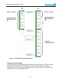
The actual backplane connection uses either 3 connectors (P0-P2) for a 3U card or 7
connectors (P0-P6) for the 6U card. P0 is reserved for the power and system control signals.
P1 has a handful of system control signals and the rest can be used for data bus connections
between modules. Any remaining unused pins are considered User I/O and are generally
routed to either the Rear Transition Module, as additional flash storage, or backup bus lines. All
connectors with the exception of P0 are generally routed in differential pairs. There are single
ended schemes listed in the standard, though they are not widely adopted as of late 2010.
-3-
Whitepaper: Introduction to VPX
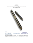
3U
6U
(Power + Control
Power + Control
High Speed Serial
Bus and/or User
I/O
High Speed Serial
Bus and/or User
I/O
User I/O –
Differential Pairs
Figure 1. VITA 46.0 VPX board connections.
Power and Control Signals
All power and system control signals are routed through P0 as noted above. The only required
control signal is the System Reset (SYSReset). Other connections such as providing a
reference clock, JTAG, and the system management Bus must be routed on the backplane but
are optional in VPX system implementations.
-4-
Whitepaper: Introduction to VPX
Power is routed through the backplane to the VPX board via 6 separate signals as noted in the
table below. Note that the 3U and 6U backplanes are inherently incompatible due to the voltage
differences on VS2.
3U1
Power Planes
6U1
VS1
+12V
+12.0/48.0V
VS2
+3.3V
Same as VS1. If 48V may
be isolated from VS1.
VS3
5V
5V
+3.3V AUX
1A Max (Optional)
1A Max (Optional)
+12V AUX
1A Max (Optional)
1A Max (Optional)
-12V AUX
1A Max (Optional)
1A Max (Optional)
1. Max module power of 276W on 3U and 768W on 6U.
P1 Connections
P1 contains 32 differential pairs numbed 1-32. These are furthered divided into transmit (Tx)
and receive (Rx) pairs for a total of 16 Tx/Rx groups. Each Tx/Rx grouping is the basis for a
high speed serial bus. Note that when present on a module the Tx/Rx groups in P1 are used
starting from the lowest numerical assignment to the highest. The VITA 46.0 specification only
references high speed serial busses and not any of the protocols that may be supported such
as PCIe, RapidI/O, or Gigabit Ethernet. This omission is purposeful. These definitions are left
for the VITA 46 dot standards.
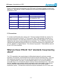
What are these VITA 46 “dot” standards I keep hearing
about?
The VITA organization has recently begun to differentiate between the minimum required
information to implement a specification and the optional features associated with it. Since the
VPX standard is designed to work with any high speed serial bus such as Serial RapidI/O™,
PCIe, Gigabit Ethernet, and others, a single standard would be very long and cluttered to
enumerate the pin out and electrical specs for the three aforementioned protocols. This is why
the “dot” standards were created to simplify organization and to help readers understand the
difference between the base requirements every design must have and the optional
implantation options. The table below outlines the major dot standards of the VITA 46.0 spec.
-5-
Whitepaper: Introduction to VPX
Dot Standard
Status1
46.1
Approved
VMEBus Signals (Hybrid) on VPX Fabric Connector
46.3
Trial Draft2
Serial RapidI/O™ on VPX Fabric Connector
46.4
Trial Draft2
PCI Express on VPX Fabric Connector
46.6
Trial Draft
2
Gigabit Ethernet External Control Plane on VPX
46.7
Trial Draft
2
Ethernet on VPX Fabric Connector
46.9
Draft
46.10
Approved
46.11
Draft
Description
PMC/XMC Rear I/O Backplane Routing
Rear Transition Modules
System Management Signals
1. Status as of 10/15/10.
2. Trial Draft standards are temporary standards that were designed specifically to
encourage compatibility among different vendors.
The VITA 46.3, 46.4, and 46.7 give implementation requirements on the three common serial
bus interfaces for use on the VPX backplane. Each standard gives pin placement and electrical
specifications and are incompatible with each other. Acromag VPX products are compliant to
VITA 46.4. They use PCI Express for communication on the backplane.
VITA 46.10-2009 is an approved standard that defines the mechanical specifications for 3U and
6U Rear Transition Modules (RTM). The module is nearly identical to its VMEbus cousin but
with a different backplane connector. As with VME, pretty much anything goes in terms of use
of the RTM.
VITA 46.11 defines the application use of the system management bus. This standard
implements an Intelligent Platform Management Interface (IPMI). This Intel standard loads
basic information from the modules prior to booting the operating system and can monitor
system health.
Lastly, VITA 46.9 brings much needed clarification for the routing of PMC and XMC Rear I/O
signals to the backplane. Compliance to this specification will allow for some standardization of
RTM modules. Note that while there is only one way to route the PMC Rear I/O signals, there
are several variations with XMC connectors. Verify that the backplane is VITA 46.9 P2w1-P64s
compliant for proper operation with Acromag’s VPX products.
-6-
Whitepaper: Introduction to VPX
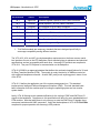
How do the VPX Modules connect on the Backplane?
Unfortunately, the key specification that VITA 46.0 leaves out is how to connect the backplanes
together. In VME, there was a parallel bus that connected the processor board to all the
remaining plug-in modules. All of the modules shared the same bus. Plug in your SBC into any
slot and the system would work.
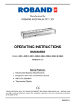
VPX Slot 3
VPX Slot 1
VPX Slot 2
Simple VPX PCIe System
VME Slot 3
VME Slot 2
VME Slot 1
Simple VME64 System
x4 PCIe
VME Parallel Bus
x4 PCIe
In a VPX system, there is a serial bus which is point to point. In this case there is no longer a
shared bus. Therefore, the backplane MUST route the serial bus from the master to each of the
slaves. In the example above, slot 1 of the VPX system routes two, 4-lane PCIe connections to
the second and third slots. This works if your SBC provides 8 lanes of PCIe and is plugged into
slot 1. However, plug-in the same SBC into VPX Slot 3 and now VPX slot 2 is unconnected.
While this is easy to understand in the simple example above, it becomes more complicated
with larger backplanes. How many signals should the backplane route to each module in a 5
slot backplane? Consider the fact they many processor boards may not have enough
resources to supply every slot with a bus connection. It gets even worse if you consider that
whatever the backplane routing, both your processor board and any plug-in modules would
have to match to the backplane for everything to function.
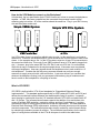
What is VPX REDI?
VPX REDI is defined within VITA 48 and standards for “Ruggedized Enhanced Design
Implementation”. This standard applies specifically for VPX systems(VITA 46.0 and 65.0) and
defines the mechanical interface between the chassis and the plug-in modules. It expands
upon the plug-in module pitch from the 0.8” standard defined in VITA 46.0 and adds both 0.85”
and 1.0” pitches. The increased size allowance permits the addition of top and bottom side
covers to facilitate ESD protection, conduction cooling, and level 2 maintenance. Level two
maintenance refers to military grade products that this field replaceable. This adds additional
Electrical Static Discharge (ESD) requirements, includes a full metal jacket around all exposed
electrical components. The mechanical plates also simplify conduction cooled chassis design
by maintaining consistency across all modules. The mechanical specifications for the various
types of cooling that are available in the VITA 48 dot specs is noted in the table below.
-7-
Whitepaper: Introduction to VPX
Dot Standard
Status1
Description
48.1-2010
Approved
REDI Air Cooling applied to VITA 46
48.2-2010
Approved
REDI Conduction Cooling applied to VITA 46
48.3
Draft
REDI Liquid Cooling Applied to VITA 46
48.5
Draft
Air cooled module electronic placement requirements
applied to VITA 46.
1. As of 10/15/10.
To simplify matters, between the various pitch boards and cooling methods available in VPX
systems, Acromag has standardized to the following three VPX board cooling types. Note that
this is subject to change based upon approval of additional draft standards and/or market
conditions.
Cooling
Method
Pitch
Description
Air
0.80″
Standard VITA 46 compliant board. Supports Front I/O. Fits in all
VPX chassis.
Conduction
Cooled
0.85″
Top Conduction Cooling plate added to VITA 46. Only supports
Rear I/O. Fits in most chassis.
Conduction
Cooled-REDI
1.00″
REDI Conduction Cooled with level 2 maintenance support. This
type of module has cover plates on both sides with no exposed
components for ESD protection. Rear I/O only. Fits only in VITA
48.2 compliant chassis.
How can all these different possible backplane, cooling, and serial protocols be
compatible with each other?
After pondering this question most companies came to the conclusion that all VPX products
would require some type of custom backplane depending upon the desired plug-in modules. In
other words, the system designer would select the modules and then create a custom
backplane that would work for them. This defeats the purpose of a having a standard in the first
place. After much discussion and debate, VITA 65.0 “OPEN VPX” was written to reign in VITA
46’s and VITA 48’s seemingly limitless configurations.
-8-
Whitepaper: Introduction to VPX
What is OPEN VPX?
Open VPX was the industry’s attempt to bring order to chaos. Open VPX methodically defines
a system of profiles that would fully explain the interactions between the backplane and plug-in
modules. The profiles are the physical mapping of resources in the system. This information
can then be used to determine compatibility.
Before diving into the actual profiles, first we need to introduce some new terminology unique
to OPEN VPX.
What is an OPEN VPX Pipe?
Definition
Pipe: A term used to characterize the total number of differential
pairs (Rx and Tx) accessible, regardless of protocol.
The pipe is used to standardize differential pair groups, regardless of protocol. There is also
specific terminology in determining the width of the pipe. See the table below. Note the
abbreviations in parenthesis next to the name. These will be used later.
Name
Differential Pairs
Example
Ultra-Thin Pipe (U)
2
x1 PCIe, 1x Serial RapidIO®
Thin Pipe (T)
4
x2 PCIe, 1000BASE-T
Fat Pipe (F)
8
x4 PCIe, 4x Serial RapidIO®, 10GBASE-KX4
Double Fat Pipe (D)
16
x8 PCIe
Pipes are easier to understand if you have a basic understanding of the serial bus protocols.
While that discussion is beyond the scope of this document, note that a single lane of PCI
Express is comprised of 2 differential pairs. One pair is dedicated to transmission (Tx), and the
other to receiving (Rx), creating a full duplex connection. In turn, this lane is represented by an
Ultra-Thin Pipe (a single pipe) within VPX. A module that supports two 4 lane PCI Express
ports is represented by two Fat Pipes. However, the Pipe itself does not represent a protocol.
Those same two Fat Pipes could also use the Serial RapidIO® protocol. This term allows us to
specify backplane capabilities, regardless of the intermediate protocol used. Acromag’s
VPX4810 products support two Fat Pipes.
-9-
Whitepaper: Introduction to VPX
What are OPEN VPX Modules?
Definition
Module: A board that conforms to defined mechanical and
electrical specifications such a 3U and 6U plug-in modules.
At first glance, a module definition appears straightforward. VITA 65.0 takes it one step further
and defines multiple module types depending on functionality. These types of modules are self
explanatory and are provided below for reference. Note the abbreviations in parenthesis next to
the name. These will be used later.
Name
Definition
Payload Module (PAY)
The module that provides hardware processing for the top
level application. (i.e. a Single Board Computer, or SBC)
Peripheral Module (PER)
An I/O module that requires a payload module to function.
Storage Module (STO)
Provides the functionality of a disk drive
Switch Module (SWH)
Provides for the switch fabric to transfer data from at least one
upstream port to multiple downstream ports. (i.e. a hub)
Bridge Module
A switch module that changes bus protocols. For example
switching from PCIe to 1000BASE-T.
The Acromag VPX product line is composed of Peripheral modules.
What is an OPEN VPX plane?
To simplify connectivity descriptions in the OPEN VPX profiles, the standard separates all
signals into 6 unique groups, called planes, as noted in the table below. Note that planes never
interconnect and are only used to clarify the purpose of the available connections on the
backplane.
Name
Definition
Control Plane
GB Ethernet Bus controller (optional, either internal or external).
Data Plane
Intramodule data transfer (i.e. system bus).
Expansion Plane
For I/O or data movement within the chassis. Miscellaneous plane.
Management Plane
VITA 46.11 Chassis (System) level management.
Utility Plane
Power, Slot level management, and identification.
User I/O
Everything that’s left. Typically used for RTM.
- 10 -
Whitepaper: Introduction to VPX
The Data plane is the most important, since those are the high speed bus connections on P1
that are used to connect modules together on the backplane. The Data Plane protocol must
match for all modules in a system to have interoperability.
The Control plane is defined by VITA 46.6 and is not required for VPX system operation. These
are Gigabyte Ethernet signals that are used to connect two separate VPX systems (i.e.
backplanes) together. These signals are often routed from a SBC to a RTM for external
connection.
The Utility Plane contains all of the power, slot level management, and system identification as
required in VITA 46.0.
The Management plane, defined in VITA 46.11, is only four signals and is not required for VPX
system operation. This plane is intended to implement the Intelligent Platform Management
Interface (IPMI).
User I/O is the term given to any backplane connections that are not part of any of the above
planes. There are no fixed requirements for these I/O.
Profiles
VITA 65.0 completely characterizes a VPX system within the scope of 4 types of profiles;
Backplane, chassis, module and slot. A brief description of each is given in the table below.
Definition
Profile: A description of the physical resource mapping
within the system.
Name
Definition
Backplane Profile
Describes number of slots, protocols supported, and the
topology for connecting the slots.
Chassis Profile
Provides information on the number of slots, power supply,
and cooling methodology.
Module Profile
Contains information on the type, size, connections, and
protocols for each plug-in module.
Slot Profile
Gives specific information on how the backplane pins are
connected for each individual slot.
Each system will have one chassis and backplane profile. There will be a slot profile for each
slot on the backplane. There is one module profile for each plug-in module in the system. The
information provided on profiles is for reference to help gain a basic understanding of VPX
systems.
- 11 -
Whitepaper: Introduction to VPX
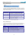
Backplane Profiles
As previously noted, the biggest problem with VITA 46 was the lack of any guidance with the
backplane routing. To clarify and to standardize the problem, Open VPX provides 14 standard
backplane configurations.
Specifically, the backplane profile describes the number of slots, the standards supported, and
the topology for connecting the boards (either star or mesh).
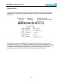
An example of a backplane profile from VITA 65 is BKP3-CEN06-15.2.2-1. The breakdown of
each item in the name is below.
BKP3- 3U Backplane
Number of
BKP6 – 6U Backplane
Slots.
Speed
grade
t d
BKP3-CEN06-15.2.2-1
VITA 65.0 Reference for
exact layout details.
Topologies
CEN = Star
DIS = Mesh
HYB = Other
For further information on the backplane profile you need to reference the VITA 65 specification
referenced in the name. In this case, turning to VITA 65 section 15.2.2.n gives us the following
graphical representation as well as other information such as compatible slot and module
profiles.
BKP3-CEN06-15.2.2.n is one example of a
backplane that is compatible with Acromag’s
VPX product line.
- 12 -
Whitepaper: Introduction to VPX
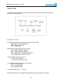
Chassis Profile
The chassis profile describes the number of slots, power provided, and the cooling method as
outlined in the example below.
Form-factor = 3U or 6U
UUU Standard Development Chassis Type {RCK | TOW | OPN}
Where RCK = 19” EIA Rack Mount
TOW = Stand-alone Tower
OPN = Open Frame
WWW Primary Power {3PA | 3PB | 1PA | 1PB}
3PA = 3 Phase, 208VAC, 50/60 Hz
3PB = 3 Phase, 400VAC 50/60 Hz
1PA = Single phase, 110/220VAC, 50/60 Hz
1PB = Single phase, 230VAC, 50/60 Hz
x Plug-in Module Cooling Type {A | C}
A = VITA 48.1 air cooled
C = VITA 48.2 conduction cooled
YYY Backplane Power Option {12H | 5VH | VEN}
12H = 12V centric power
5VH = 5V centric power
VEN = Supplier Defined
z Chassis Manager {N | Y } – Yes or no
Backplane Profile Name: Backplane profile discussed in previous section if installed.
- 13 -
Whitepaper: Introduction to VPX
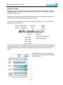
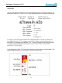
Module Profiles
The module profile contains information on the type and size of plug-in modules, the pipes
available for use and the protocol associated with those pipes. An example module profile is
given below.
Module Profile
3U or 6U
Number of
Data Plane
VITA 65 reference.
Defines the protocol on the
MOD3-PER.2F-16.3.1-2
Type of Module
Type of Pipe.
PAY = Payload
U = Ultra Thin
PER = Peripheral
T = Thin
SWH = Switch
F= Fat
STO = Storage
D= Double Fat
Note that if there are pipes available on the expansion plane a number and letter would
immediately follow the 2F. For example a module with 2 fat pipes on the data plane and four
thin pipes on the expansion pane would be 2F4T. If there were pipes on the control plane then
a number and letter would follow the expansion plane reference. Refer to the VITA 65
specification for further details on this, and on the specific protocols referenced.
- 14 -
Whitepaper: Introduction to VPX
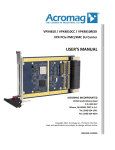
Slot Profile
The slot profile contains information on how the backplane pins are connected for each slot. An
example slot profile is SLT3-PER-1F-14.3.2 and is broken down into its component parts below.
Module Profile
3U or 6U
Number of
Data Plane
VITA 65 reference.
Defines the protocol on
SLT3-PER-1F-14.3.2
Type of Module
PAY = Payload
PER = Peripheral
SWH = Switch
STO = Storage
Type of Pipe.
U = Ultra Thin
T = Thin
F= Fat
D= Double Fat
Once again, if there were pipes available on the Expansion plane a number and letter would
immediately follow the 1F. For example, a module with 1 fat pipe on the data plane and four
thin pipes on the expansion pane would be 1F4T. If there were pipes on the control plane then
a number and letter would follow the expansion plane reference. Refer to the VITA 65
specification for further details.
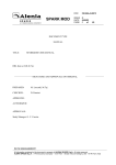
As with backplane profiles, VITA 65 provides a graphical representation for all slot profiles. The
graphical representation of the SLT3-PER-1F-14.3.2 example is below.
- 15 -
Whitepaper: Introduction to VPX
How can I tell if VPX modules and backplane are compatible?
This is perhaps the first and most important question when building a VPX system, and yet with
the propagation of backplane, module, and slots profiles it is one of the most difficult to answer.
There are multiple compatible module profiles for each slot, and multiple compatible slot profiles
for each space on the backplane and, therefore, no simple one size fits all profile check is
adequate. Acromag tries to simplify that answer for you in our White Paper Will Acromag’s
VPX4810 work in my System?. This information is available from either your local sales
representative or on our website at www.acromag.com.
Anything else I need to know?
There are plenty of other VITA standards in the works that you should monitor which may have
an effect on future VPX systems. Specifically, there is work to add a new connector for both
XMC and VPX so that they can support the next generation of high speed serial buses such as
PCIe 3.0. While the goal of these connectors is to be pin compatible with their predecessors,
they are not mechanically compatible. See the table below for a brief description of these and
other draft standards.
VITA STD1
Description
VITA 62 – Draft
Standardize power supply size/connectors.
VITA 68 – Draft
Define Electrical specifications and characteristics for VPX backplanes.
VITA 66 – Draft
2
Fiber Optics on VPX Fabric Connector
VITA 67 – Draft
2
Analog/RF on VPX Fabric Connector
VITA 60 – Draft
Alternative VPX connector (next gen buses)
VITA 61 – Draft
Alternative XMC connector (next gen buses)
1. As of 10/15/10.
2. Removed from VITA 46 dot standards due to incompatibility with backplane.
As a final note if you read the VITA specifications on VPX the pins of the backplane connectors
are referred to as wafers. They are called wafers since the connector does not employ metal
pins in the traditional sense but rather small printed circuit boards with gold fingers.
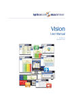
Further Reading
All of the VITA specifications noted in this document are available at www.vita.com.
Acromag White Paper: Will Acromag’s VPX4810 work in my System?
Acromag User’s Manual: VPX4810 VPX XMC/PMC Carrier
Additional Acromag documents are available on our web site www.acromag.com.
- 16 -
Whitepaper: Introduction to VPX
About the Author:
Acromag is an international corporation that has been manufacturing and developing
measurement and control products for more than 50 years. Acromag offers a complete line of
industrial I/O products including process control instruments, distributed I/O systems, embedded
I/O modules, and data acquisition boards.
For more information about Acromag products, contact the Sales Department at
Tel: (248) 295-0310, Fax: (248) 624-9234, or e-mail: [email protected].
Our web site address is www.acromag.com.
- 17 -