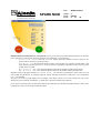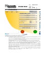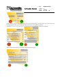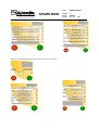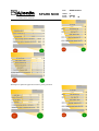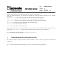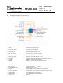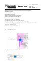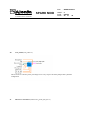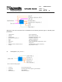
1
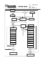
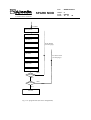
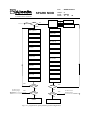
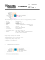
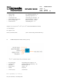
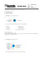
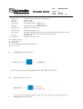
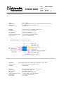
DOC 40 40 SPARK MOD SPAZIO A F IN MECC AN IC A CO MPAN Y : SD-MA-AI-0013 ISSUE : 2 DATE : 6/06/03 PAGE : 1 of 40 DOCUMENT TYPE MANUAL TITLE: SPARKMOD USER MANUAL DRL Item or D.R.D. No: SIGNATURE AND APPROVALS ON ORIGINAL PREPARED: M. Leccardi, M.Taj CHECKED: D. Panzieri APPROVED: AUTHORIZED: APPROVALS: Study Manager: G. C. Cassisa DATA MANAGEMENT: All information contained in this document is property of ALENIA SPAZIO S.p.A.. All rights reserved. ALENIA SPAZIO S.p.A. - A Finmeccanica Company - Turin Plant – Strada Antica di Collegno, 253 - 10146 Turin, Italy DOC 40 40 SPARK MOD SPAZIO A F IN MECC AN IC A CO MPAN Y : SD-MA-AI-0013 ISSUE : 2 DATE : 6/06/03 PAGE : 2 of 40 DOCUMENT CHANGE RECORD ISSUE DATE REASON FOR CHANGE First 2 26/03/03 22/05/03 Additional paragraph AFFECTED PARAGRAPHS 7. DOC 40 40 SPAZIO SPARK MOD A F IN MECC AN IC A CO MPAN Y TABLE OF CONTENTS 1. INTRODUCTION 2. STARTING THE PROGRAM 3. THE MAIN WINDOW 4. USING STK 5. SELECTING THE DATA 6. THE OUTPUT WINDOW 7. PROGRAM AND ROUTINES DESCRIPTION : SD-MA-AI-0013 ISSUE : 2 DATE : 6/06/03 PAGE : 3 of 40 DOC 40 40 SPAZIO SPARK MOD A F IN MECC AN IC A CO MPAN Y 1. : SD-MA-AI-0013 ISSUE : 2 DATE : 6/06/03 PAGE : 4 of 40 INTRODUCTION The SPARK MODEL program has been developed to evaluate and compute the main characteristics of a Space Solar Power system. The software has been written for a user with some experience in the SSP issues. In the present manual the following convention are assumed: in bold the names of input and output files in italic the titles of the dialog windows in courier the labels of the input and output fields. The SPARK MODEL program has been developed with the software LABVIEW 5.1 of National Instruments with the operating system Windows NT, the program has been successfully tested also with Windows 2000 and Windows 98. The program has a graphical user interface, optimised, following ESA request, for a screen resolution of 1024x768 pixels. To employ all the options of the SPARK MODEL program it is required to have installed the STK 4.3 program from AGI, available freely for the research institutions. AGI suggests, for the installation and execution of STK a minimum disk space of 300MB and 128MB of RAM, but for the present application a Pentium III with 800MHz clock and 256MB RAM is a minimum suggested requirement. For any question and problem about STK contact [email protected] or visit www.stk.com web page. Warning: the SPARK MODEL program reads the paths of the executable file of STK and of the report files folder from a text file called path.txt, you should edit this file writing the right paths for your system (e.g. C:\Program files\AGI\stk\4.3\bin4.3\stk.exe and C:\stk\user1). The input data for the calculation performed by SPARK MODEL program are stored in ASCII files (filename.txt) and reflect the present technological knowledge for the various elements (e.g. photovoltaic cells). This data format allows the user to keep updated these files with the new technological improvements. Warning: after any modification these files should be stored in the same directory they were before and with the same name and structure (data fields are separated with tab). 2. STARTING THE PROGRAM You can start the SPARK MODEL program double clicking on its icon. The program displays a main window and several dialog windows used to get input parameters and output the results of calculation. In the almost every window there are two round buttons: clicking on the green one you proceed with the calculations, with the red one you quit the program. In the input windows to the right of every data filed you can see a small grey button with a question mark , clicking on it you can read a brief description of the command. After a welcome screen the program asks you if you want to open an old project or to create a new one. To select the files the standard “Save as…” and “Open” dialog windows are used. The projects are stored in ASCII files with the spark extension (e.g. projectname.spark). Each time the program is executed three files are generated: • the project (with the .spark extension by default) which stores all the input data • the output file (the string _output.dat is added to the project name e.g. projectname_output.dat) which stores the relevant input and the output data. • the loss table file (the string _loss.dat is added to the project name e.g. projectname_loss.dat) which stores the power lost in each step of the project. If you create a new project the following dialog window is opened: DOC 40 40 SPAZIO A F IN MECC AN IC A CO MPAN Y SPARK MOD : SD-MA-AI-0013 ISSUE : 2 DATE : 6/06/03 PAGE : 5 of 40 With the check box on the left (USE STK) you can choose if you want to input the orbital parameters for the solar power satellite or to use the STK program (checked); the parameters you can input are: Access time (day) is the time, in a year, during which the satellite can deliver power to the ground station; the time is expressed in days Elevation (°) is the minimum elevation angle of the satellite seen from the ground station. This angle should be greater than zero; to avoid an excessive spreading of the beam on the receiving area it should not be too small. Max distance (km) is the maximum distance between the satellite and the ground station. Min distance (km) is the minimum distance between the satellite and the ground station. With the switch on the right, labelled GEO OTHER ORBIT, you can select a geostationary orbit, in this case you can’t modify the parameters, or manually input all of them. All these controls are visible only if you uncheck the USE STK checkbox. The grey box on the top right displays error messages if the chosen values are not valid, in this case your are not allowed to proceed with the calculations. A similar box is present in all the input windows. If you open an existing project all the input windows described later are automatically filled with the values of the chosen project, but you can freely modify all of them. DOC 40 40 SPAZIO A F IN MECC AN IC A CO MPAN Y 3. SPARK MOD : SD-MA-AI-0013 ISSUE : 2 DATE : 6/06/03 PAGE : 6 of 40 THE MAIN WINDOW The main window of the SPARK MODEL program is shown above. The right part of the window contains the input controls: AVAILABLE POWER at location is the total power delivered to the final application, you can select the unit of measurement from watts to gigawatts. Application is the kind of application you want to study, there are three possible choices: Space to Earth, Space to space and Space to high altitude platforms. You can select the Power generation system between photovoltaic cells and sun pumped laser. The button SELECT ORBIT calls STK, the SPARK MODEL program displays a window with a summary of the tasks to be performed with STK. This window will be better described later. The Radiator’s parameters group includes three commands: the Use default checkbox allows you to choose if you want to use default values for dissipator’s characteristics or to manually input them. The two parameters are Mass and Dissipation capability. If the operating temperature of an element is known, these values are ignored and the dissipation capability is calculated directly from the temperature itself. The button SELECT SATELLITE’S STRUCTURE opens a dialog window you can use to input the percentage in mass of the satellite due to three elements: Support structure, Power management and Orbital control. DOC 40 40 SPAZIO SPARK MOD A F IN MECC AN IC A CO MPAN Y : SD-MA-AI-0013 ISSUE : 2 DATE : 6/06/03 PAGE : 7 of 40 - The button SELECT PLATFORM’S STRUCTURE opens the same dialog window. In this you can use it to input the percentage in mass of the platform due to the same three elements. Platform altitude is the altitude over the sea level of the atmospheric platform. This control, together with the previous one, is visible only if you select space-to-platform application. The input process is split into three main sections: 1) the general configuration that includes all the choices made within the main window 2) the power generation section 3) the power transmission section When each one of these steps has been completed the corresponding red “led” on the top left of the main window turns to green. During the input process in the left part of the main window you can read the parameters you have already chosen. 4. USING STK It this manual it is assumed you know how to use the STK program. The SPARK MODEL program reads the access time, the elevation angle and the distances from two output reports of STK. In this chapter are listed only the tasks required to create these reports. The same tasks are listed in the help window that appears when you click on the SELECT ORBIT button. You have to create a scenario or to open one with one satellite and one facility. The orbit of the satellite should be circular and should be computed over an year period to average the seasonal effects. In the satellite lighting constraints select direct sun. In the facility constraint dialog select the minimum elevation angle to avoid an excessive spreading of the beam on the receiving area. Select the facility and compute access with the satellite. Warning: do not select the satellite and compute access with the facility because it would give a wrong value for the elevation angle. Create the access report and the AER (Azimuth Elevation Range) report and save them in the folder written in the second line of path.txt file in the data folder. Warning: use always the names access.dat for the access report and dist.dat for the AER report. The recorded reports are automatically renamed by the SPARK program with a progressive number that depends on the date of creation. When the four values has been read the instruction window is automatically closed and you can also close STK. 5. SELECTING THE DATA The program opens several different input windows according to the options selected in the main window. With space-to-Earth or space-to-space application and photovoltaic power generation the following windows are displayed: DOC 40 40 SPAZIO SPARK MOD A F IN MECC AN IC A CO MPAN Y : SD-MA-AI-0013 ISSUE : 2 DATE : 6/06/03 PAGE : 8 of 40 In this window you can select the kind of beam used to transfer energy, selecting laser you can also choose the wavelength band. There are two bands matching two minima of atmospheric absorption. Clicking on SELECT CELL and SELECT CONCENTRATOR the following windows are displayed: When the laser beam option is selected the following windows appear: DOC 40 40 SPAZIO SPARK MOD A F IN MECC AN IC A CO MPAN Y : SD-MA-AI-0013 ISSUE : 2 DATE : 6/06/03 PAGE : 9 of 40 When the microwave beam option is selected the following window appears: With laser power production and space-to-Earth or space-to-space application the following windows are displayed: DOC 40 40 SPAZIO SPARK MOD A F IN MECC AN IC A CO MPAN Y With Space-to-platform application and photovoltaic power generation : SD-MA-AI-0013 ISSUE : 2 DATE : 6/06/03 PAGE : 10 of 40 DOC 40 40 SPAZIO SPARK MOD A F IN MECC AN IC A CO MPAN Y With Space-to-platform application and laser power generation : SD-MA-AI-0013 ISSUE : 2 DATE : 6/06/03 PAGE : 11 of 40 DOC 40 40 SPAZIO SPARK MOD A F IN MECC AN IC A CO MPAN Y : SD-MA-AI-0013 ISSUE : 2 DATE : 6/06/03 PAGE : 12 of 40 In all these windows, with the pop-up menu, you can select from different databases the device you want to use (e.g. the cell type) or, if present, select Custom and manually digit the data. If you select a device from the database you can't modify the data. If the data are not physically achievable (e.g. efficiency greater than 100%) the top right grey box displays an error message and you can't proceed in the input process until you write an allowed value. In the bottom grey box you can read additional information about the device you selected or, if you select Custom type, you can write your own comments that will appear in the output file. In some windows there is also a checkbox labelled NASA radiator values, when checked the radiator specific mass from NASA Fresh Look (April 4, 1997) will be used in the following calculations, otherwise the specific mass will be calculated from the chosen operating temperature. 6. THE OUTPUT WINDOW There are five different output windows according to the chosen configuration; all of them have the same structure. In the left part are displayed all the input parameters grouped for device, in each group you can scroll the lines DOC 40 40 SPAZIO SPARK MOD A F IN MECC AN IC A CO MPAN Y : SD-MA-AI-0013 ISSUE : 2 DATE : 6/06/03 PAGE : 13 of 40 using the little up and down arrow buttons. In the right part there are the grouped output values: masses and surfaces of the elements of the SSP and power density on the receiving station. In all the output windows are also present some buttons for saving and printing functions, for the program management. Save project as… allows to save the project with a user chosen file name and path. Save out as… allows to save the output data with a user chosen file name and path. Save loss as… allows to save the loss table output with a user chosen file name and path. Print output allows to print the output data using notepad program. Print loss same as before for the loss table. View loss shows on the screen the loss table. In the different windows some buttons labelled Modify… allow you to recalculate output changing only the selected device. (e.g. Modify uW allows to modify the characteristics of the microwave generator) Restart button allows you to restart the program with a new project. Quit button has the obvious meaning. 7. PROGRAM AND ROUTINES DESCRIPTION This section presents the program and main routines definition in terms of inputs, outputs and their functional relationships. Fig. 7.1 presents the program routines while Fig 7.2 (a,b,c) contains the program logical flow DOC 40 40 SPAZIO A F IN MECC AN IC A CO MPAN Y SPARK MOD : SD-MA-AI-0013 ISSUE : 2 DATE : 6/06/03 PAGE : 14 of 40 Fig 7.1 program routines DOC 40 40 ISSUE : 2 DATE : 6/06/03 PAGE : 15 of SPARK MOD SPAZIO : SD-MA-AI-0013 A F IN MECC AN IC A CO MPAN Y start scr YES New? NO STK NO man orbit YES load conf general configuration call stk Struct par YES * StP? NO GEN PV PV param Select cell f Select conc f LASER laser gparam Select cell l Laser gen area L/µW ? µW LASER # Select µW cell area trans area PV area recten area pwr dens pwr dens out data 3 PV+µW mass save conf out data 1 loss table 3 save conf YES Modify loss table 1 NO YES Restart NO Modify NO Restart STOP NO STOP Fig 7.2- a program flow (direct pumped laser and PV-µW configurations) YES YES 40 DOC 40 40 SPARK MOD SPAZIO A F IN MECC AN IC A CO MPAN Y ISSUE : 2 DATE : 6/06/03 PAGE : 16 of # LASER laser param Select cell l cell area l To PV Param (see first page) PV area PV+L mass pwr dens To start screeen (see first page) out data 2 save conf loss table 2 Modify YES NO Restart YES NO STOP Fig 7. 2 b program flow (PV-Laser configuration) : SD-MA-AI-0013 40 DOC 40 40 SPARK MOD SPAZIO A F IN MECC AN IC A CO MPAN Y * YES GEN PV : SD-MA-AI-0013 ISSUE : 2 DATE : 6/06/03 PAGE : 17 of PV param 40 Select cell f Select conc f LASER laser param laser g param Select cell l Select cell l Microw Param Microw Param cell area stp Laser gen StP PV area PV area trans area trans area recten area recten area PV+L mass PV+µW mass PV+µW mass pwr dens pwr dens out data 5 out data 4 save conf save conf loss table 5 YES To start screen (see first page) Modify NO YES Restart NO STOP loss table 4 Modify YES NO Restart YES NO STOP Fig 7.2- c program flow (space-platform-ground configuration) To start screen (see first page) DOC 40 40 SPAZIO SPARK MOD A F IN MECC AN IC A CO MPAN Y 1. Call_STK ( call_STK.vi) • • • • access: satellite access time (day/year) Elevation: satellite elevation (deg) max distance: satellite max distance from ground receiving plant min distance: satellite min distance from ground receiving plant 2. Cm_m_km^2 (cm_m_km^2.vi) 3. freql.onda (da freq a lung d’onda.vi) This VI calculates the wavelength starting from the frequency • f: Frequency • Lunghezza d’onda : Wave length = 3 * 108/ f Where 3* 108 m/sec= C = velocity of light : SD-MA-AI-0013 ISSUE : 2 DATE : 6/06/03 PAGE : 18 of 40 DOC 40 40 SPARK MOD SPAZIO A F IN MECC AN IC A CO MPAN Y 4. : SD-MA-AI-0013 ISSUE : 2 DATE : 6/06/03 PAGE : 19 of 40 pwrdens (densita` di potenza.vi) This VI calculates the power density in the receiver center and the average power density at destination • • • • • Pwr (W): Wavelength: Trans eff (fr): Rec area: Beam: • • • Dist (km): Coll eff (fr): trans area (m^2): • • peak pwr density (W/m^2): PWR den: transmitted power = Pt wavelenght = L atmospheric efficiency (loss) rectenna area in case laser is used, defines the wavelenght: 0 865 nm 11.03 µm distance Km =D geometric collection efficiency transmitting area = At power density at rectenna center vector including Average pwr density, Peak pwr density, 2nd peak pwr density, 2nd peak radius Peak pwr density = ((At *Pt)/(L2 * D2)) * Trans eff Average power density = (Trans eff * Coll eff * Pt) / Rec area 2nd peak pwr density = peak pwr density * 0.0175 2nd peak radius = 1.635 * L*D/(sqrt(At/π) 5. • trans-area (diametro ant trasm mod.vi) Pant (W) : Antenna input power (W) DOC 40 40 SPARK MOD SPAZIO A F IN MECC AN IC A CO MPAN Y ISSUE : 2 DATE : 6/06/03 PAGE : 20 of • atm trans (fract) eff.gen. (fraz): op.temp. (°K) Atmospheric efficiency (loss)=atm µw generation efficiency = n Operating temperature = T • • • • Trans diameter km: power density on transmitti... Pwr on rectenna (W): Trans area m^2: Transmitting area diameter = Dt RF power density = denspot Power at rectenna = Psurec Transmitting area = At • • denspot= (n/(1-n))*(5.67*T4 *10-8) (5.67 *10-8 is the stefan-Boltzmann constant) At = Pant/denspot Dt= sqrt((4* At)/π) Psurec=(0.98*atm)*Pant 6. (0.98 = beam forming antenna efficiency) recten area (diametro della rectenna_mod.vi) • • • • • trans diam (km): coll eff (fract) Elevation: Distance (km): f(GHz): transmitting source diameter = Dt geometric collection efficiency = eta elevation angle = E distance = D frequency • rect area (m^2): rectenna area tau=sqrt(ln(1/(1-eta))) Dr=((4*L*D*tau)/(3.1416*Dt))/1000 : SD-MA-AI-0013 40 DOC 40 40 SPARK MOD SPAZIO A F IN MECC AN IC A CO MPAN Y : SD-MA-AI-0013 ISSUE : 2 DATE : 6/06/03 PAGE : 21 of 40 r e c = D * s i n ( a t a n ( D r / D ) ) / s i n ( E - a t a n ( D r /D ) ) D L= wave length = 3 * 108/ f Dt = spacetenna diameter Dr = Rectenna Diameter 7. Cell+concef (eff_con eff nota_mod.vi) • • • cel eff (%) Conc ratio: trasm Eff (fract) • PV eff(fract) cell efficiency =eff concentration ratio concentrator effciency cells+concentrators efficiency ndec = log (Conc ratio) PV eff = (eff+(0.02*ndec))* trasm Eff (the PV efficiency increases of about 2% for each decade of concentrion ratio; then the overall efficiency is degraded due the concentrator efficiency) 8. Ground PV area (Ground_PV_area.vi) • Laser PWR: Laser generated power DOC 40 40 SPARK MOD SPAZIO A F IN MECC AN IC A CO MPAN Y • • • • • Coll eff: Maxpwr cell Distance: Elevation: Wavelenght • • MAXpwr: Atm trans (fr): • • laser trans area: Pwr warning • • PV area: PV radius (m): : SD-MA-AI-0013 ISSUE : 2 DATE : 6/06/03 PAGE : 22 of 40 geometric collection efficiency = eta max power density allowed by selected PV cell distance = Dist elevation angle = E wavelenght: selection : 0 865 nm = L 11.03 µm = L Max power density allowed by laser optics atmospheric effciency (loss) laser transmitting area = At alert that the peak power density is greater than the maximum allowed by selected ground Pvcells, the fpcos spot at receiver is then enlarged ground PV area ground PV area radius = Rec Tau =sqrt((ln(1/(1-eta))) Ar = (tau*L*Dist) 2/At Dr = Sqrt (Ar/π) Rec = Dist*sin(atan(Dr/Dist))/sin(E-atan(Dr/Dist)) PV area = π * Rec 2 9. GW_MW_kW (GW_MW_kW.vi) 10. kg_ton_tons (kg_ton_tons.vi) 11. lasergen_area (lasegen_area.vi) DOC 40 40 SPAZIO SPARK MOD A F IN MECC AN IC A CO MPAN Y : SD-MA-AI-0013 ISSUE : 2 DATE : 6/06/03 PAGE : 23 of 40 This Vi provide laser section sizing for Direct solar pumped laser configuration Po(W): Struct %: Laser mass (kg/w): Max pwr: diss mass: atm trans(fract): laser to DC conv eff (fract): rectenna coll eff fract: Diss capability sun to laser(fract): Power required at end user = Po Structural part percentage laser mass per generated watt Max power density allowed by laser optics thermal dissipator mass per area (Kg/m2) atmosphere efficiency (loss)= atm Ground PV cells conversion efficiency= cell ground geometric collection fraction = coll dissipation capability for m2 sun to laser conversion efficiency = laser laser pwr(W) total area (m^2) laser dissipator area: Laser gen mass Laser generated power = Plaser Laser area = Suptot Thermal dissipators area Array including : overall mass, laser section mass, dissipator mass Suptot=Po/(1350*laser*cell*atm*coll); Plaser=Suptot*1350*laser; Pinlaser=Suptot*1350; Laser dissipator area = (laser * Pinlaser)/ Diss capability laser mass = Plaser *laser mass Laser diss. Mass = laser dissipator area * diss mass Mirror mass (if mirrors are used )= (Plaser/Max pwr)* mirror unit mass (Kg/m2) Total mass = (laser mass+Laser diss.Mass+Mirror mass)*Struct%+(laser mass+Laser diss Mass+Mirr.mass) 12. Laser parameters (laser_param_dati_file.vi) DOC 40 40 SPARK MOD SPAZIO A F IN MECC AN IC A CO MPAN Y : SD-MA-AI-0013 ISSUE : 2 DATE : 6/06/03 PAGE : 24 of 40 • • • • band: Applicazione Old_trans_laser : Elevation laser bandwith type of application (space to earth, space to platform, space to space) previously saved laser parameters array elevation angle • • • • • • Max pwr 2 trans laser eff atm. trans(fraz) laser mass collection efficiency (fract) Trans laser par Max power density allowed by optical system DC to Laser conversion efficiency atmospheric absorbtion mass per transmitted watt (Kg/W) ground geometric collection fraction Arrays laser characteristics 13. Laser g param (Laser_sun_pump_dati_file.vi) With this vi, the user can select from a data base the transmission laser type or manually input several parameter • • • Application Old_trans_laser : Elevation type of application (space to earth, space to platform, space to space) previously saved laser parameters array elevation angle • • • • • • • Max pwr 2 gen laser eff atm. trans(fraz) laser mass collection efficiency (fract) Gen laser par Wavelenght2 Max power density allowed by optical system Laser generation efficiency atmospheric absorption mass per transmitted watt (Kg/W) ground geometric collection efficiency Arrays of laser characteristics wave length DOC 40 40 SPAZIO SPARK MOD A F IN MECC AN IC A CO MPAN Y 14. : SD-MA-AI-0013 ISSUE : 2 DATE : 6/06/03 PAGE : 25 of 40 Lasergen_area_Stp (Lasergen_area_Stp.vi) This Vi provides sizing for laser and µW sections in the “space – platform- ground” application • • • Po(W): Sat Struct %: Laser mass (kg/w): diss mass: atm trans(fract): laser to DC conv eff (fract): laser coll eff fract: Diss capability sun to laser(fract): µw gen eff µw coll eff: cell temp uW temp NASA diss: Power required at end user = Po Structural part percentage laser mass per generated watt thermal dissipator mass per area (Kg/m2) atmosphere efficiency (loss)= atm Ground PV cells conversion efficiency= cell laser collection PV efficiency = laserce dissipation capability for m2 sun to laser conversion efficiency = laser µw generation efficiency =DC to µw ground geometric collection efficiency laser pwr(W) =µwce Platform PV cell operative temperature Platform RF section operative temperature = uWT NASA RF section operative temperature • • • • laser pwr(W) antenna output power Sat area Laser gen sat mass • • • cell diss mass uW diss mass "laser" area Laser generated power = Plaser RF antenna power = Pant array including laser area, platform PV area (Suptot) array including: laser section mass, laser dissipator mass, total satellite mass mass of platform PV cells dissipator mass of platform RF section dissipator laser area • • • • • • • • • • • DOC 40 40 SPAZIO SPARK MOD A F IN MECC AN IC A CO MPAN Y : SD-MA-AI-0013 ISSUE : 2 DATE : 6/06/03 PAGE : 26 of 40 Suptot=Po/(1350*laser*laserce*cell*cable*DCtouW*uWce*atm*uWtoDC*antenna); Plaser=Suptot*1350*laser; Pinlaser=Suptot*1350; Pincell=Plaser*laserce; PinuW=Pincell*cell*cable; Pant=PinuW*DCtouW*antenna; Celldiss=10^(2.94-0.00624*CellT+2.4e-6*CellT^2); uWdiss=10^(2.94-0.00624*uWT+2.4e-6*uWT^2); cable = 0.92 cable efficiency (loss) antenna = 0.98 antenna efficiency (loss) laser section mass = Plaser *Laser mass (Kg/W) Laser diss. Mass = laser* Pinlaser/Diss capability * diss mass Mirror mass (if mirrors are used )= (Plaser/Max pwr)* mirror unit mass (Kg/m2) Laser gen sat mass = (laser mass+Laser diss.Mass+Mirror mass)*Struct%+(laser mass+Laser diss Mass+Mirr.mass) cell diss mass= cell*Pincell*Celldiss uW diss mass = DC to µw PinµW* µWdiss 15. Load_conf (load_conf.vi) This vi loads last saved configuration data 16. loss_table1 (loss_table1.vi) DOC 40 40 SPAZIO A F IN MECC AN IC A CO MPAN Y 17. SPARK MOD : SD-MA-AI-0013 ISSUE : 2 DATE : 6/06/03 PAGE : 27 of Loss_table2 (loss_table2.vi) This VI writes in a file the power percentage lost in every step for the PV-laser configuration 18. Loss_table3 (loss_table3.vi) This VI writes in a file the power percentage lost in every step for the Direct-pumped laser configuration 19. Loss_table4 (loss_table4.vi) 40 DOC 40 40 SPAZIO SPARK MOD A F IN MECC AN IC A CO MPAN Y 20. : SD-MA-AI-0013 ISSUE : 2 DATE : 6/06/03 PAGE : 28 of 40 Loss_table5 (loss_table5.vi) This VI writes in a file the power percentage lost in every step for the dierct pumped laser -platform configuration 21. Microwave Parameters (Microwave_param_dati_file.vi) DOC 40 40 SPARK MOD SPAZIO A F IN MECC AN IC A CO MPAN Y : SD-MA-AI-0013 ISSUE : 2 DATE : 6/06/03 PAGE : 29 of 40 With this VI the user can select from a database the microwave generator type or manually input parameters Applicazione: Old uW eff.atm.(fraz) transmission frequency 2 temp eff 2 Nasa diss 2 mass 2 uW par rectenna collection eff (fr... uW par • • • • • • • • • • 22. type of application last saved µw data file atmospheric efficiency (loss) trasmission frequency operative temperature RF section efficiency NASA used operative temperature values mass/power ground rectenna collection efficiency µw parameters array Orbit Options (orbit_manual.vi) This VI calls the STK program • • • • Access 2 elevation 2 distance 2 Min distance 2 access time (days/year) elevation angle with respetc to ground station max distance minimum distance DOC 40 40 SPAZIO A F IN MECC AN IC A CO MPAN Y 23. SPARK MOD ISSUE : 2 DATE : 6/06/03 PAGE : 30 of Output Data1 (Output_data1.vi) This VI writes in a file the Input and Output Data for the PV-µw configuration 24. Output Data2 (Output_data2.vi) : SD-MA-AI-0013 40 DOC 40 40 SPAZIO A F IN MECC AN IC A CO MPAN Y SPARK MOD : SD-MA-AI-0013 ISSUE : 2 DATE : 6/06/03 PAGE : 31 of 25. Output Data3 (Output_data3.vi) 26. Output Data4 (Output_data4.vi) This VI writes in a file the Input and Output Data for the direct pumped laser configuration 40 DOC 40 40 SPAZIO A F IN MECC AN IC A CO MPAN Y SPARK MOD : SD-MA-AI-0013 ISSUE : 2 DATE : 6/06/03 PAGE : 32 of 40 This VI writes in a file the Input and Output Data for the Pvlaser -platform configuration 27. Output Data5 (Output_data5.vi) This VI writes in a file the Input and Output Data for the dierct pumped laser -platform configuration DOC 40 40 SPAZIO SPARK MOD A F IN MECC AN IC A CO MPAN Y 28. : SD-MA-AI-0013 ISSUE : 2 DATE : 6/06/03 PAGE : 33 of 40 Pesi_Pv+Laser (Pesi_Pv+Laser.vi) This VI calculate the mass of PV and laser sections in the PV-laser configuration • • • • • • • • • • cell area (m^2) laser diss mass(ton) trans area (m^2) struct mass % cell diss mass (ton) Laser unit mass (kg/w) conc unit mass(kg/m^2) Laser pwr conc area (m^2) cell unit mass(kg/m^2) PV cells area mass of laser section dissipators Laser area structural part mass percentage mass of PV section dissipators laser mass/watt concentrators mass/area emitted laser power concentrators area PV cells mass/area • • • PV mass (ton) Laser mass(ton) total mass (ton) PV section overall mass (includes dissipators and concentrators) Laser section overall mass DOC 40 40 SPAZIO SPARK MOD A F IN MECC AN IC A CO MPAN Y 29. : SD-MA-AI-0013 ISSUE : 2 DATE : 6/06/03 PAGE : 34 of 40 Pesi_Pv+uW (pesi_PV+uW.vi) • • • • • • • • • • struct mass % antenna area(m^2) antenna diss mass (ton) cell area (m^2) cell unit mass(kg/m^2) conc area (m^2) conc unit mass(kg/m^2) cell diss mass (ton) Laser unit mass (kg/w) uW gen mass (ton) structural part mass percentage antenna area mass of RF section dissipators PV cells area PV cells mass/area concentrators area concentrators mass/area mass of PV section dissipators laser mass/watt µw generator section mass • • • PV mass (ton) RF mass(ton) total mass (ton) PV section overall mass (includes dissipators and concentrators) RF section overall mass 30. Photovoltaic Parameters (PV_param_pop_up.vi) DOC 40 40 SPAZIO SPARK MOD A F IN MECC AN IC A CO MPAN Y 31. : SD-MA-AI-0013 ISSUE : 2 DATE : 6/06/03 PAGE : 35 of 40 Photovoltaic parameters (PV_Param_Stp.vi) With th s VI the user can select the values for PV cells, Laser and concentrators in the Space to platform configuration 32. save_conf (save_conf.vi) 33. Select Cell (select_cell_dati_file.vi) DOC 40 40 SPARK MOD SPAZIO A F IN MECC AN IC A CO MPAN Y : SD-MA-AI-0013 ISSUE : 2 DATE : 6/06/03 PAGE : 36 of 40 Mass 2 cell+conc BOL eff 2 Op temp 2 selected cell old cell Whit this VI the user can select a PV cell type for solar acquisition from a database and manually modify several parameters 34. Select cell (select_cell_laser.vi) Band old cell Op temp 2 Max pwr 2 BOL eff 2 selected cell Mass 2 Whit this VI the user can select a PV cell type for laser acquisition from a database and manually modify several parameters 35. Select Concentrator (select_conc_dati_file.vi) old conc Conc ratio Transmission Mass conc selected concentrator Whit this VI the user can select a concentrator type from a database and manually modify several parameters 36. Cell area (Superficie celle Dt output rapp_conc_mod.vi) DOC 40 40 SPAZIO SPARK MOD A F IN MECC AN IC A CO MPAN Y : SD-MA-AI-0013 ISSUE : 2 DATE : 6/06/03 PAGE : 37 of This VI calculates the PV area for PV-µw configuration, and the dissipators mass • • • Po(W) conc? Nasa diss conc ratio uW temp atm trans (fract) uW gen eff (fract) rectenna coll eff (fract) Cell T Sun to DC eff(fract) Power required at end user = Po Use of concentrator ? NASA value for RF section operative temperature concentration ratio µw generator operative temperature = µwT Atmosphere efficiency (loss) = atm µw generation efficiency = n rectenna geometric collection efficiency = conv PV cells operative temperature CellT PV cells efficiency =cell • • • • • cell area(m^2) conc area(m^2) Pant (W) cell dissipator mass(ton) antenna dissipator mass(ton) space PV cells area concentrators area RF power PV section dissipators mass = RF section dissipators mass • • • • • • • Ptrasm=Po/(n*antenna*atm*conv*RFtoDC*Cable); RF to DC =0.89 Cable = 0.92 Antenna = 0.98 Suptot=(Ptrasm/(cell*1350)); Pant=Suptot*1350*cell*n*Cable*antenna; Pinant=Suptot*1350*cell*Cable; uWdiss=10^(2.94-0.00624*uWT+2.4e-6*uWT^2); Celldiss=10^(2.94-0.00624*CellT+2.4e-6*CellT^2); 37. Laser Cell Surface Area (Superficie celle laser.vi) 40 DOC 40 40 SPAZIO SPARK MOD A F IN MECC AN IC A CO MPAN Y : SD-MA-AI-0013 ISSUE : 2 DATE : 6/06/03 PAGE : 38 of • • • • • • • • • • • Po(W) conc? laser to DC conv eff fract Cell temp conc ratio diss mass atm trans(fract) DC to laser conv eff (fract) rectenna coll eff fract Diss capability sun to DC(fract) Power required at end user = Po Use of concentrator ? ground laser to DC conversion efficiency =lasertoDC PV cells operative temperature CellT concentrationr ratio laser dissipator mass/area Atmosphere efficiency (loss) = atm Laser efficiency = n ground station geometric collection efficiency = conv max laser optic dissipation capability PV section eficiency • • • • • • • cell area(m^2) conc area(m^2) Pout_celle (W) laser pwr(W) laser dissipator area cell diss mass(ton) laser diss mass(ton) space PV cells area concentrators area space PV section output power =Ptrasm laser emitted power = Plaser PV section dissipators mass laser section dissipators mass Ptrasm=Po/(n*atm*conv*LasertoDC*Cable); Suptot=(Ptrasm/(cell*1350)); Plaser=Suptot*1350*cell*n*Cable; Pinlaser=Suptot*1350*cell*Cable; Celldiss=10^(2.94-0.00624*CellT+2.4e-6*CellT^2); Cable=0.92 40 DOC 40 40 SPAZIO SPARK MOD A F IN MECC AN IC A CO MPAN Y 38. : SD-MA-AI-0013 ISSUE : 2 DATE : 6/06/03 PAGE : 39 of 40 Cell Surface Area (superficie celle Stp.vi) This VI provides sizing for space PV in the PV-laser – platform configuration • • • • • • • • • • • • Po(W) laser to DC conv eff DCtouW Cell Temp cell laser temp uW temp nasa diss uW coll eff diss mass Diss capability conc ratio conc? DC to laser conv eff (fract) Laser coll eff Sun to DC Power required at end user = Po ground laser to DC conversion efficiency =lasertoDC platform µw generation efficiency PV cells operative temperature CellT platform PV cells operative temperature platform µw section operative temperature NASA operative temperature value rectenna geometric collection efficiency laser dissipator mass/area max laser optic dissipation capability concentrationr ratio Use of concentrator ? Laser efficiency = n platform PV cell efficiency space PV section eficiency • • • • • • • • • cell area(m^2) conc area(m^2) cell diss mass(ton) laser diss mass(ton) laser dissipator area (m^2) cell diss mass 2 (ton) uW diss mass (ton) Pant Laser PWR StP space PV cells area concentrators area space PV section dissipators mass laser section dissipators mass area of laser dissipators platform PV dissipator mass platform RF section dissipator mass platform radiated power laser emitted power • • • Poutcell=Po/(DCtoL*antenna*atm*Lce*LasertoDC*Cable^2*DCtouW*atm*uWce*uWtoDC); Suptot=(Poutcell/(suntoDC*1350)); Pinlaser=Suptot*1350*suntoDC*Cable; Pincell2=Pinlaser*DCtoL*Lce; PinuW=Pincell2*LasertoDC*Cable; DOC 40 40 SPAZIO SPARK MOD A F IN MECC AN IC A CO MPAN Y Pant=PinuW*DCtouW*antenna; Plaser=Suptot*1350*suntoDC*DCtoL*Cable; uWdiss=10^(2.94-0.00624*uWT+2.4e-6*uWT^2); Celldiss=10^(2.94-0.00624*CellT+2.4e-6*CellT^2); : SD-MA-AI-0013 ISSUE : 2 DATE : 6/06/03 PAGE : 40 of 40