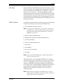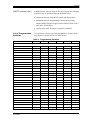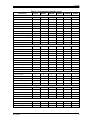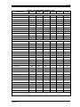
1
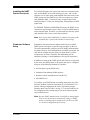
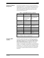
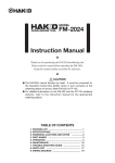
8/16/00
HART Communication
with GF868, XGM868,
XGS868, and XMT868
Flowmeters
Panametrics Model GF868, XGM868, XGS868, and XMT868
ultrasonic flowmeters may be modified to permit two-way
communication with a HART communication device. This requires
the installation of a HART option card in the flowmeter. The option
card generates a 4-20 mA analog output signal that can be read by the
HART device. Proceed to the appropriate section for detailed
instructions on installing and/or using the HART option card.
Installing the HART
Option Card
To install a HART option card in your flowmeter, complete the
following steps:
!WARNING!
This procedure should be performed only by
qualified service personnel.
1. Disconnect the main power from the flowmeter.
!WARNING!
Failure to disconnect the power before proceeding
may result in serious injury.
2. Refer to your User’s Manual for step-by-step instructions, and
install the HART option card in Slot 6 for a GF868 flowmeter or
in Slot 2 for an XGM868, XGS868, or XMT868 flowmeter.
IMPORTANT: If a MODBUS option card is installed in Slot 5 of a
GF868 flowmeter, the HART option card in Slot 6
will be ignored.
3. Interconnect the HART option card and the HART device as
shown in Figure 1 below.
HART
Communications
Device
1
2
Flowmeter
Option Card
Connector
250 ohms
+
24 Volt DC
Power
Supply
Figure 1: Option Card Wiring
913-262A
1
8/16/00
Installing the HART
Option Card (cont.)
For a GF868 flowmeter, the option card connector is mounted on the
card, and the HART device leads should go to pins 1 and 2 of this
connector. As for other option cards installed in the same meter as the
HART option card, the HART device will not recognize any option
card installed in Slots 3-5 and it will only recognize option cards
installed in Slots 1-2 if they are Analog Input, Analog Output, or RTD
option cards.
For XGM868, XGS868, and XMT868 flowmeters, the HART device
connections must be made to pins 1 and 2 of 12-pin terminal block J2
on the terminal board. Therefore, you must make sure that any option
card installed in Slot 1 does not use these terminals.
Note: Refer to your User’s Manual for a complete description of the
available Slot 1 option cards and their terminal usage.
Flowmeter Software
Setup
Panametrics flowmeters that are shipped with a factory-installed
HART option card require no special setup procedures by the user.
The meter automatically configures itself for HART communication
on startup. However, for field-installation of a HART option card, the
card must be configured in the factory test menu before it will be
recognized by the meter. Thereafter, the initialization will be
automatic on startup. Consult Panametrics for specific instructions.
In addition to setting up the HART option card so that it is recognized
by the meter, the analog output of the option card may be configured
using any of the following methods (if available):
•
the flowmeter keypad (GF868 only)
•
Instrument Data Manager (IDM) software
•
Remote Control Communications Unit (RCCU)
•
the HART device
To configure your HART option card analog output using any of the
first three methods, follow the instructions in your flowmeter User’s
Manual. During configuration, the choice of parameter must be
limited to those listed in Table 1 on page 3. To use the HART device
for configuration of the analog output, refer to the instructions that
came with that device.
Note: Because HART communication is unreliable at analog outputs
below 4 mA, the flowmeter automatically changes a HART
option card analog output configuration of 0-20 mA or OFF
to a 4-20 mA configuration upon startup.
913-262A
2
8/16/00
Flowmeter Software
Setup (cont.)
Some flowmeter parameters can only be read by the HART device
during startup. Therefore, it is recommended that both the flowmeter
and the HART device be rebooted after any reprogramming of the
HART option card analog output. Failure to do so may result in
erroneous information or a communication failure between the
flowmeter and the HART device.
Table 1: Valid HART Parameters and Units
Parameter
English Units
Metric Units
Velocity
ft/sec
m/s
Volumetric (liquid)
gal/s, gal/m, gal/h,
mgal/day, cuf/s, cuf/m,
cuf/h, mcf/day, bbls/s,
bbl/m, bbl/h, mbl/d,
acre-inch/day
l/s, l/m, l/h, ml/d, cum/s,
cum/m, cum/h, mcm/d,
bbl/s, bbl/m, bbl/h,
mbl/d
Volumetric (gas)
acf/m, acf/h, scf/m, scf/h acm/h, scm/h, scm/d
+Tot, -Tot (liquid)
gal, cuf,bbl, acre-in,
acre-ft
liter, cum, bbl
+Tot, -Tot (gas)
acf, scf
acm, scm
Mass Flow
lb/s, lb/m, lb/h, mlb/d,
ton/m, ton/h, mton/d
kg/s, kg/h, mkg/d, tne/m,
tne/h, tne/d
+Mass, -Mass
lb, ton
kg, tne
Power
kbtu/h, kw
mcal/h, kw
+Energy, -Energy
btu, kw-hr
mcal, kw-hr
Temperature
°F
°C
Pressure
psia
bar, bara
Mol Weight
none
none
NOTE: “acf” is reported as “normal cubic feet” in HART. Also, “Mega”
units (i.e. mgal/day, mcf/day, etc.) are reported as standard units x 10^6 in
HART. For example, 1 mgal is 1x10^6 gal in HART.
Using the HART
Interface
913-262A
The HART communications option card installed in Panametrics
flowmeters has been successfully tested with the Rosemount 275
Hand-Held Communicator and the Rosemount AMS ComputerBased Communications Software. Although some flowmeter
functions may be performed via the HART device, many other
functions (i.e. data logging, site file uploading, site file downloading,
printing, etc.) must still be programmed by the methods described in
the flowmeter’s User’s Manual. This is because the HART protocol
was developed for use with simple transmitters and it cannot handle
the multitude of sophisticated functions built into the Panametrics
flowmeters.
3
8/16/00
Unit Types
Due to limitations of the HART protocol, only those unit types listed
in Table 1 on page 3 are acceptable. If a meter parameter is set to any
other measurement units, the HART device displays an “Unknown
Enumerator, Can not resolve” error message and may terminate
communications entirely. In some cases, both the Hart device and the
flowmeter may have to be rebooted to clear the error. To address this
potential problem, the flowmeter has been programmed to force all
measurement units to HART compliant units if a HART option card is
detected upon startup.
HART Functions
After HART communications has been properly set up, the following
flowmeter functions may be accessed via the HART device:
•
static temperature and static pressure
Note: To view the static temperature or pressure for a channel via
the HART device, the fixed value for that parameter must be
assigned to that channel at the flowmeter. See your User’s
Manual for instructions.
•
tracking windows (XMT868 only)
•
minimum and maximum soundspeed (XMT868 only)
•
2-path error handling
•
velocity averaging response time
•
static density
•
error handling
•
mA error level (if selected)
•
clear totals
Note: Refer to your User’s Manual for a complete description of
each of the above functions.
When information is viewed through the HART device, the input
variable always appears as either Channel 1 Temperature or Channel
1 Pressure. Although these inputs are not necessarily assigned to
Channel 1, the HART protocol labels all inputs as channel-specific.
For example, a Slot 1 analog input that is programmed at the meter as
a temperature input assigned to Channel 1, Channel 2, Both, or
Neither is always reported by the HART device as a Channel 1
Temperature input.
Note: Inputs cannot be assigned via the HART device. Also, any
input assigned as “Special” is always reported as a Channel 1
Temperature input by the HART device
913-262A
4
8/16/00
HART Functions (cont.)
List of Programmable
Variables
In addition to the functions listed on the previous page, the following
procedures may be performed through the HART device:
•
calibration and setup of the HART option card analog output
•
calibration and some programming of analog inputs, analog
outputs, and RTD inputs on option cards installed in Slots 0 (all), 1
(all), and 2 (GF868 only).
•
viewing some of the flowmeter’s diagnostic parameters.
For convenient reference, all of the programmable variables for the
four flowmeter models are listed in Table 2 below.
Table 2: Programmable Variables
Description
Ch1, Ch2, or Ave vel
Ch1, Ch2, or Ave vol
Ch1, Ch2, or Ave mdot
Ch1, Ch2, or Ave power
Ch1, Ch2, or Ave Temper
Ch1, Ch2, or Ave Pressure
Ch1, Ch2, or Ave Mw
Ch1, Ch2, or Ave +tot
Ch1, Ch2, or Ave -tot
Ch1, Ch2, or Ave +mass
Ch1, Ch2, or Ave -mass
Ch1, Ch2, or Ave +energy
Ch1, Ch2, or Ave -energy
Ch1 or Ch2 Ssup
Ch1 or Ch2 ssDO
Ch1, Ch2, or Ave tUP
Ch1, Ch2, or Ave tDO
Ch1, Ch2, or Ave deltaT
Ch1 or Ch2 peak%
Ch1, Ch2, or Ave DeltaT(s)
Ch1, Ch2, or Ave DeltaT(M)
Ch1 or Ch2 qUP
Ch1 or Ch2 qDOWN
Ch1 or Ch2 ampUP
Ch1 or Ch2 ampDOWN
Ch1 or Ch2 peak#UP
Ch1 or Ch2 peak#DOWN
Ch1, Ch2, or Ave t.S
913-262A
Format*
R/W/B*
XMT868
XGS868
Channel Process Variables
f.p.
R
Y
Y
f.p.
R
Y
Y
f.p.
R
Y
Y
f.p.
R
if energy
N
f.p.
R
N
Y
f.p.
R
N
Y
f.p.
R
N
N
f.p.
R
Y
Y
f.p.
R
Y
Y
f.p.
R
Y
Y
f.p.
R
Y
Y
f.p.
R
if energy
N
f.p.
R
if energy
N
f.p.
R
Y
Y
f.p.
R
Y
Y
f.p.
R
Y
Y
f.p.
R
Y
Y
f.p.
R
Y
Y
f.p.
R
Y
Y
f.p.
R
N
if meas
f.p.
R
N
if meas
f.p.
R
Y
Y
f.p.
R
Y
Y
f.p.
R
Y
Y
f.p.
R
Y
Y
f.p.
R
Y
Y
f.p.
R
Y
Y
f.p.
R
if energy
N
XGM868
GF868
Y
Y
if mass
N
Y
Y
N
Y
Y
if mass
if mass
N
N
Y
Y
Y
Y
Y
Y
if meas
if meas
Y
Y
Y
Y
Y
Y
N
Y
Y
Y
N
Y
Y
Y
Y
Y
Y
Y
N
N
Y
Y
Y
Y
Y
Y
if meas
if meas
Y
Y
Y
Y
Y
Y
N
5
8/16/00
Table 2: Programmable Variables (cont.)
Description
Ch1, Ch2, or Ave t.R
Ch1, Ch2, or Ave t.S-t.R
Ch1 or Ch2 inco1
Ch1 or Ch2 onco2
Ch1 or Ch2 Rpowr
Ch1 or Ch2 Rqual
Ch1 or Ch2 Repp
Ch1, Ch2, or Ave c3
Ch1, Ch2, or Ave Temp_super
Ch1, Ch2, or Ave Rho
Ch1 or Ch2 Err code
Ch1 or Ch2 re#
MeterType (Model)
#Channels
2-Path?
Resp_time
Static Density?
Static Density Value
Error Mode
Aout Error Level
Meter Units (Eng. or Metric)
EnergyMeter?
Clear-totals?
Ch1 Fixed Temp
Ch1 Fixed Press
Ch1 Tracking?
Ch1 Min Sound Spd
Ch1 Max Sound Spd
Ch2 Fixed Temp
Ch2 Fixed Press
Ch2 Tracking?
Ch2 Min Sound Spd
Ch2 Max Sound Spd
Slot 0 A or B Device
Slot 0 A or B Type
Slot 0 A or B Chan
913-262A
Format*
R/W/B*
XMT868
XGS868
Channel Process Variables (cont)
f.p.
R
if energy
N
f.p.
R
if energy
N
f.p.
R
if transfl.
N
f.p.
R
if transfl.
N
f.p.
R
if transfl.
N
f.p.
R
if transfl.
N
f.p.
R
if transfl.
N
f.p.
R
Y
Y
f.p.
R
N
Y
f.p.
R
N
Y
int
R
Y
Y
f.p.
R
Y
N
Global Meter Information
int
R
Y
Y
int
R
Y
N
int
B
Y
N
int
B
Y
Y
int
B
Y
Y
f.p.
B
Y
Y
int
B
Y
Y
f.p.
B
Y
Y
uchar
B
Y
Y
uchar
R
Y
N
int
W
Y
Y
CH1 Information
f.p.
B
N
Y
f.p.
B
N
Y
int
B
Y
N
f.p.
B
Y
N
f.p.
B
Y
N
CH2 Information (if applicable)
f.p.
B
N
Y
f.p.
B
N
Y
int
B
Y
N
f.p.
B
Y
N
f.p.
B
Y
N
Slot Information
uchar
R
Y
Y
uchar
B
Y
Y
uchar
B
if 2-Ch
if 2-Ch
XGM868
GF868
N
N
N
N
N
N
N
Y
N
N
Y
N
N
N
N
N
N
N
N
Y
N
N
Y
N
Y
N
N
Y
Y
Y
Y
Y
Y
N
Y
Y
N
N
Y
Y
Y
Y
Y
Y
N
Y
Y
Y
N
N
N
Y
Y
Y
Y
N
N
N
Y
Y
Y
Y
if 2-Ch
Y
Y
if 2-Ch
N
N
N
N
6
8/16/00
Table 2: Programmable Variables (cont.)
Description
Format*
R/W/B*
XMT868
Slot Information (cont.)
Slot 0 A or B Variable
uchar
B
Y
Slot 0 A or B Units
uchar
R
Y
Slot 0 A or B Zero
f.p.
B
Y
Slot 0 A or B Span
f.p.
B
Y
Slot 1 or 2 Active
int
R
Y
Slot 1 or 2 A, B, C, or D Device
uchar
R
if active
Slot 1 or 2 A, B, C, or D Type
uchar
B
if active
Slot 1 or 2 A, B, C, or D Chan
uchar
B
if active
Slot 1 or 2 A, B, C, or D Variable
uchar
B
if active
Slot 1 or 2 A, B, C, or D Units
uchar
R
if active
Slot 1 or 2 A, B, C, or D Zero
f.p.
B
if active
Slot 1 or 2 A, B, C, or D Span
f.p.
B
if active
HART Variables
Universal Rev
uchar
R
Y
Software Rev
uchar
R
Y
Transmitter Rev
uchar
R
Y
Hardware Rev
uchar
R
Y
Device ID
uchar
R
Y
PollAddress
uchar
B
Y
Message
uchar24
B
Y
Tag
uchar6
B
Y
Descriptor
uchar12
B
Y
Date
uchar3
B
Y
Final Assy No
uchar3
B
Y
Derial No.
uchar3
R
Y
Pvt. Label Dist
uchar
R
Y
Pri Var Code
uchar
R
Y
Alarm Select
f.p.
B
Y
Write Protect Code
uchar
B
Y
Config Chgd Flag
uchar
B
Y
Response Preambles
uchar
B
Y
HART Device
uchar
R
Y
HART Type
uchar
B
Y
HART Channel
uchar
B
Y
HART Variable
uchar
B
Y
HART Units
uchar
R
Y
HART Zero
f.p.
B
Y
HART Span
f.p.
B
Y
XGS868
XGM868
GF868
Y
Y
Y
Y
Y
if active
if active
if active
if active
if active
if active
if active
Y
Y
Y
Y
Y
if active
if active
if active
if active
if active
if active
if active
Y
Y
Y
Y
Y
if active
if active
if active
if active
if active
if active
if active
Y
Y
Y
Y
Y
Y
Y
Y
Y
Y
Y
Y
Y
Y
Y
Y
Y
Y
Y
Y
Y
Y
Y
Y
Y
Y
Y
Y
Y
Y
Y
Y
Y
Y
Y
Y
Y
Y
Y
Y
Y
Y
Y
Y
Y
Y
Y
Y
Y
Y
Y
Y
Y
Y
Y
Y
Y
Y
Y
Y
Y
Y
Y
Y
Y
Y
Y
Y
Y
Y
Y
Y
Y
Y
Y
* Format - f.p. = IEEE floating point, int = integer, uchar = unsigned character ucharX = X bytes of
unsigned characters. R/W/B - R = read only, W = write only, B = read or write via HART
913-262A
7