1
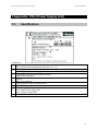
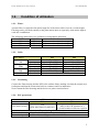
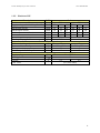
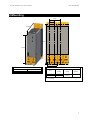
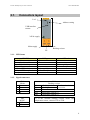
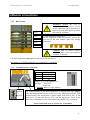
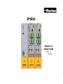
PSU User’s manual Rev. 0 … 2010 1 Parker Hannifin S.p.A. S.B.C. Division user’s manual PSU This user manual is for the standard version of the converter. All information in this user manual, including methods, techniques and concepts described herein, are proprietary information of Parker Hannifin Divisione S.B.C. – EME Division and of its licensees, and they shall not be copied or used without express authorization. Parker Hannifin S.p.A. Divisione S.B.C. is committed to a continuous product upgrade and reserves the right to modify products and user manuals at any time without prior notice. No part of this user manual may be howsoever reproduced without previous consent by Parker Hannifin S.p.A. S.B.C. Division. Cod 1007141600 2 Parker Hannifin S.p.A. S.B.C. Division user’s manual PSU 1. APPENDIX: PSU (POWER SUPPLY UNIT) .......................................................... 4 1.1. Identfication ............................................................................................................... 4 1.2. Condition of utilization .............................................................................................. 5 1.2.1. Filters.................................................................................................................. 5 1.2.2. Cable................................................................................................................... 5 1.2.3. Grounding........................................................................................................... 5 1.2.4. PSU protections.................................................................................................. 5 1.2.5. Hardware PSU.................................................................................................... 6 2. MOUNTING ............................................................................................................ 7 2.1. Connectors layout....................................................................................................... 8 2.1.1. LED Status ......................................................................................................... 8 2.1.2. Signal connectors ............................................................................................... 8 3. MODULE CONNECTIONS..................................................................................... 9 3.1.1. Rail system ......................................................................................................... 9 3.1.2. Communication connection................................................................................ 9 3.2. Mains supply ............................................................................................................ 10 4. PARAMETERS SET-UP ...................................................................................... 10 4.1.1. Voltage supply.................................................................................................. 10 5. PSU ALARMS...................................................................................................... 11 6. REVISION HISTORY OF THE USER MANUAL .................................................. 12 3 user’s manual PSU Parker Hannifin S.p.A. S.B.C. Division 1.Appendix: PSU (Power Supply Unit) 1.1. Identfication 8 1 2 3 4 6 5 7 7 Explanation: Type designation 1 The complete order designation of the device (2 - 4). PSUPx0: Mains module 3AC 230...480V, nominal power in 1kW (10=10kW, 20=20kW) 2 D6: Designation nominal supply Configuration and parameterization interface 3 USB: USB connection Options 4 Mxx: I/O extension 5 Unique number of the particular device 6 Date of factory test Nominal supply voltage 7 Power Input: Input supply data Power Output: Output data 8 CE compliance 4 user’s manual PSU Parker Hannifin S.p.A. S.B.C. Division 1.2. Condition of utilization 1.2.1. Filters A mains filter is required in the mains input line if the motor cable exceeds a certain length. Filtering can be provided centrally at the plant mains input or separately at the mains input to each axis combination. The following mains filters are available for independent utilization: PSU Order No. Condition P10 NFI03/01 Reference axis combination 6x10m P10 NFI03/02 Reference axis combination 6x50m P20 NFI03/03 Reference axis combination 6x50m 1.2.2. Cable PSU Model 24VDC X9 Braking resistor X40 Mains X41 PE P10 P20 Section 4mm2 (AWG8) 4mm2 (AWG8) Tightening torque 1.2 Nm (M5) 1.2 Nm (M5) Section 0.25÷4mm2 (AWG23÷11) 0.25÷4mm2 (AWG23÷11) Tightening torque 0.5 Nm (M4) 0.5 Nm (M4) 2 Section 0.5÷6mm (AWG20÷10) 0.5÷16mm2 (AWG20÷6) Tightening torque 1.2 Nm (M5) 1.7 Nm (M5) 2 Section 10mm (AWG6) 1.2.3. Grounding Connect the filter housing and the PSU to the cabinet frame, making sure that the contact area is adequate and that the connection has low resistance and low inductance. Never mount the filter housing and the device on paint-coated surfaces! 1.2.4. PSU protections Mains connection P10 Fuse (short circuit) Fuse Short-circuit proof P20 50A 25A MTP: S203U-K 50(440VAC) MTP: S203UP-K 25(480VAC) 2 circuit breakers in line are required Control voltage 24VDC Delayed action fuse, due to capacitive load conditional (internally protected with 3.15AT) 5 Parker Hannifin S.p.A. S.B.C. Division user’s manual PSU 1.2.5. Hardware PSU Description UdM Value Models P10 P20 Supply voltage (3AC±10% _ 50-60Hz) VAC 230 400 480 230 400 480 Rated input current Arms 22 22 18 44 44 35 Rated output current Arms 18 18 15 36 36 30 Peak output current (2 sec) Arms 36 36 30 72 72 60 Power kW 6 10 10 12 20 20 Internal capacitance µF 550 1175 Total capacity applicable µF 2400 4000 External braking resistor Minimum braking resistance Ω 27 15 Recomended nominal power W 500 ÷ 1500 500 ÷ 3500 Pulse power (1s) kW 22 40 Maximum permissibile peak current A 13 15 Control stage Supply voltage V= 21…27VDC Max ripple Vpkpk 0,5 Current A 0,2 0,3 EMC Filter (see filters table) 6 user’s manual PSU Parker Hannifin S.p.A. S.B.C. Division 2.Mounting 101mm 50,5mm 263mm 90° 400mm 360mm 96mm 100mm PSU Weight Size 1 Size 2 3,95 kg 6,5 kg Size Dimensions Lenght Height [mm] [mm] 1 2 50 100 360 (410**) Depht (*) [mm] 270 (*) without connectors (**) with clamps 7 user’s manual PSU Parker Hannifin S.p.A. S.B.C. Division 2.1. Connectors layout Led Address setting USB interface RS485 24Vdc supply Main supply Braking resistor PE 2.1.1. LED Status STATUS No 24Vdc Error of main module Pow. Volt. is built up Phase failure Address CPU active Address CPU completed Ready LED green Off Off On Flashes quickly Flashes slowly On LED red Off On Flashes quickly Flashes slowly Off 2.1.2. Signal connectors 1 2 3 4 X41 Mains L1 L2 L3 PE 1 2 X9 24VDC +24V 0Vdc +R -R PE T1R T2R X40 Braking resistor + Braking resistor No short-circuit protection - Braking resistor PE Temperature switch (*) Temperature switch (*) (*) If the external braking resistor hasn’t the temperature sensor, connect T1R to T2R. 8 user’s manual PSU Parker Hannifin S.p.A. S.B.C. Division 3.Module connections 3.1.1. Rail system 24Vdc 0Vdc - DCbus Earth Protective covers: the user is responsible for protective covers and/or additional safety measures in order to prevent damages to persons and electric accidents. Use the dedicate fixing plates. On the right side of the last module, and on the left side of the first module insert the closing protection: + DCbus Caution! Risk of Electric Shock. Discharge time of the bus capacitor is approx. 5 minutes. External components may not be connected to the rail system. Maximum no. of TPDM modules in a combination: 15 modules 3.1.2. Communication connection IN OUT IN OUT IN OUT Address setting Switch Value upon ON 1 16 2 32 3 64 Range: 0,16,32,48,64,80,96,112 Settings: left: OFF right: ON st 1 Module address = basic address The communication in the axis combination is implemented via a SSK28 cable and double RJ45 sleeves on the device top. Beginning with the TPD (mains module) the connection is always made from X30 to X31 of the next device. On the first device (X31) and the last device (X30) in the multi-axis combination, a bus termination plug (BUS07/01) is required. Serial connection of up to 32 axes (or 15 modules) 9 Parker Hannifin S.p.A. S.B.C. Division 3.2. user’s manual PSU Mains supply The PSU series is designed for fixed connection to TN networks (TN-C, TN-C-S or TN-S). Please note that the line-earth voltage may not exceed 300VAC. • When grounding the neutral conductor, mains voltages of up to 480VAC are permitted. • When grounding an external conductor (delta mains, two-phase mains), mains voltages (external conductor voltages) of up to 300VAC are permitted. Servo controllers which are to be connected to an IT network must be provided with a separating transformer. Then the PSU device is operated locally like in a TN network. The secondary sided center of the separating transformer must be grounded and connected to the PE connector of the PSU. 4.Parameters set-up N.B.: This operation must be executed only by the first axis connected to the PSU. 4.1.1. Voltage supply The default status of the drive is configured to 400VAC (=560V DC). For all other cases, it’s necessary to set the correct value of the voltage [3-phase VACsupply * √2 = VDCbus]: 230V AC 3-phase Æ Pr206 = 325 400V AC 3-phase Æ Pr206 = 565 480V AC 3-phase Æ Pr206 = 680 To activate the new configuration, it’s necessary to save the parameter and restart the PSU unit. 10 user’s manual PSU Parker Hannifin S.p.A. S.B.C. Division 5.PSU alarms Malfunction error code Pr23 Pr24 b0 b1 b2 b3 b4 24 b5 b6 Alarm Power supply not 3phases Undervoltage PSU Over voltage PSU Over temperature Over load braking resistor Temperature switch Over load on DC-bus Over current on DC-bus b7 b14 b15 AC supply configuration Time-out data exchange Remedies Check the main supply Check the main supply. Check the set up of the parameter Pr206 (by the first axis connected to the PSU). Check the main supply Check the environment temperature. Check the cooling fans and for any restrictions to air flow. Check the cycle and if it’s necessary use an external braking resistor. Check the connection of the temperature switch (X40). Short circuit on Braking control circuit. The current required is more than the current that can be supplied Check for any mechanical blockage and make sure the motor is the appropriate size for its current use. Check the motor connections and any phase-phase or phase-ground short-circuits. Check the length and type of the motor cable in use. Make sure a mains filter isn’t connected to the motor! Check the configuration (Pr206 of the first axis connected to the PSU) of the mains supply because it’s not correct. Check the serial connection. 11 Parker Hannifin S.p.A. S.B.C. Division user’s manual PSU 6.Revision history of the User Manual - Rev 0 – … 2010 First edition For other informations log into website www.sbcelettronica.com. Arranges to the manual data can be made by the manufacturer without advance notice. The data shown in the manual correspond to the specifications relating to the revision date 12