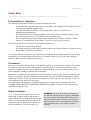
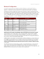
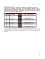
1
Ethernut Version 2.1 Hardware Manual Manual Revision: 2.0 Issue date: February 2008 Copyright 2003-2008 by egnite GmbH. All rights reserved. egnite makes no warranty for the use of its products and assumes no responsibility for any errors which may appear in this document nor does it make a commitment to update the information contained herein. egnite products are not intended for use in medical, life saving or life sustaining applications. egnite retains the right to make changes to these specifications at any time, without notice. All product names referenced herein are trademarks of their respective companies. Ethernut is a registered trademark of egnite GmbH. Contents Declaration of Conformity............................................................................................ 4 About the Ethernut 2.1 Board....................................................................................... 5 Ethernut Features.................................................................................................... 5 Block Diagram........................................................................................................ 6 LED Indicators........................................................................................................ 6 Serial Ports............................................................................................................ 6 Ethernet Port.......................................................................................................... 6 Expansion Port........................................................................................................ 7 Power Supply......................................................................................................... 7 Watchdog Timer..................................................................................................... 7 System Clock......................................................................................................... 7 Flash ROM............................................................................................................. 8 Static RAM............................................................................................................ 8 EEPROM................................................................................................................ 8 Upgrading from Previous Ethernut Revisions................................................................ 8 Quick Start................................................................................................................ 9 Prerequisites for Operation....................................................................................... 9 Precautions............................................................................................................ 9 Board Installation.................................................................................................... 9 Testing the Board...................................................................................................... 11 Ethernet Controller Read/Write Loop........................................................................ 11 Jump to Bootloader............................................................................................... 12 SRAM Read/Write Loop.......................................................................................... 12 Send Broadcasts Loop........................................................................................... 12 Exit BaseMon....................................................................................................... 12 Network Configuration............................................................................................... 13 DHCP/BOOTP Method............................................................................................ 14 Fixed IP Address................................................................................................... 14 Testing Network Operation..................................................................................... 14 Jumper Configuration................................................................................................ 15 Jumper Overview.................................................................................................. 15 Serial Ports........................................................................................................... 15 JTAG Port............................................................................................................ 18 Hardware Expansion.................................................................................................. 19 Expansion Port...................................................................................................... 19 Analog Input Port.................................................................................................. 21 Troubleshooting........................................................................................................ 22 Sick Ethernuts.......................................................................................................... 25 Schematics.............................................................................................................. 25 Ethernut 2.1 Hardware Manual Declaration of Conformity Konformitätserklärung Declaration de Conformité We / Wir / Nous egnite GmbH, 44575 Castrop-Rauxel, Germany declare under our sole responsibility that the product erklären in alleiniger Verantwortung, dass das Produkt declarons sous notre seule responsabilite que le produit Ethernut 2.1 Rev-B to which this declaration relates is in conformity with the following standards auf das sich diese Erklärung bezieht, mit den folgenden Normen übereinstimmt auquel se refere cette declaration est conforme aux normes EN 61000-6-1:2001 EN 61000-6-2:2001 EN 61000-6-3:2001 EN 61000-6-4:2001 following the provisions of Directive gemäss den Bestimmungen der Richtlinie conformement aux dispositions de Directive Electromagnetic compatibility 91/336/EWG Castrop-Rauxel, 31. March 2006 Harald Kipp General Manager egnite GmbH 4 About the Ethernut 2.1 Board About the Ethernut 2.1 Board Low-cost Ethernet capability can be added to many embedded applications. Since its introduction in the year 2000, Ethernut boards have been used to develop some of the most innovative products. Using the hardware, firmware, software and tools, developers have everything they need to develop leading networked devices rapidly and affordable. The board is well suited for application development in a wide range of applications. Some areas are: • • • • • • Networked sensors Remote monitoring equipment Alarm service providing Remote diagnose and service Industrial Ethernet applications Home and building control Ethernut Features Ethernut 2.1 is a small (80 x 100 mm) board combining Atmel's ATmega128 RISC micro controller with SMSC's LAN91C111 Ethernet controller. The main features are: • • • • • • • • • • • • • • ATmega128 RISC microcontroller with up to 16 MIPS throughput Full duplex IEEE 802.3 compliant 10/100 Mbps Ethernet controller with on-board RJ- 45 connector Two serial ports, RS-232 at DB-9 connector and half duplex RS-485 at screw terminal 128 kByte in-system programmable Flash ROM and 512 kByte serial Dataflash 4 kByte in-system programmable EEPROM 32 kByte SRAM plus 480 kByte banked SRAM Up to 28 programmable digital I/O lines 8-channel, 10-bit analog/digital converter Two 8-bit and two 16-bit timer/counters Watchdog timer for enhanced reliability LED indicators for power supply and Ethernet activity Single power supply 9-12V DC Lead-free and RoHS compliant Industrial temperature range: -40°C to 85°C (-40°F to 185°F) 5 Ethernut 2.1 Hardware Manual Block Diagram The block diagram shows the main components. Definitely the most important part is the ATmega128 microcontroller. It’s a quite complex chip and described in detail in Atmel’s ATmega128 data sheet. Almost all pins are routed to the Ethernut expansion port, a 64-pin connector, which can be used to add custom hardware like the Medianut MP3 decoder with LCD interface. The microcontroller provides two UART channels, which are routed to the on-board RS-232 and RS-485 level shifters. A Xilinx CPLD is used to implement an address latch and the bank select logic of the external 512kByte SRAM. It further generates the LAN Controller's chip select. Memory Map The microcontroller uses a Harvard Architecture, where memory is divided into data and pro gram memory. The following table shows the data memory layout. Byte Address 0x0000 - 0x001F 0x0020 - 0x005F 0x0060 - 0x00FF 0x0100 - 0x10FF 0x1100 - 0x7FFF 0x8000 - 0xBFFF 0xC000 - 0xCFFF 0xD000 - 0xDFFF 0xE000 - 0xEFFF 0xFF00 - 0xFFFF 6 Description CPU Registers I/O Registers (Note 1) Extended I/O Registers (Note 1) Fast Internal RAM, no wait states required Fixed External RAM Banked External RAM, 30 pages, 16k each Ethernet Controller Registers (Note 2) Unused, Available for Custom Extensions (Note 3) Unused, Available for Custom Extensions (Note 4) Bank Select Register (Note 5) (Note 1) About the Ethernut 2.1 Board Note Note Note Note Note 1: 2: 3: 4: 5: See ATmega128 datasheet See LAN91C111 datasheet. Not fully decoded, registers are mirrored. Recommended for fast access. Recommended for slow peripherals. Writing bank number to (0xFF00 + bank number) selects the bank page at 0x8000. The layout of the program memory is a follows: Word Address 0x0000 - 0x0045 0x0046 - 0xEFFF 0xF000 - 0xF7FF 0xF800 - 0xFBFF 0xFC00 - 0xFDFF 0xFE00 - 0xF7FF Description Vector Table Initialization, RTOS and Application Sections Boot loader Section, if BOOTSZ = 00b (Note 1) Boot loader Section, if BOOTSZ = 01b (Note 1) Boot loader Section, if BOOTSZ = 10b (Note 1) Boot loader Section, if BOOTSZ = 11b (Note 1) Note 1: Available for applications if not used by boot loader JTAG Port While Ethernut’s software offers serveral boot loader capabilities over RS-232 or WARNING: Never plug an SPI programming Ethernet, program code is initially uploaded adapter into the Ethernut 2.1 JTAG connec through the JTAG interface, using a JTAG tor. This will result in a power supply shortcut programming adapter. Recommended and will at least blow the fuse on the Ethernut adapters are the SP Duo and the SP Duo board. 2, but almost any AVR compatible JTAG adapter should work. When used with Atmel's AVR JTAGICE mkII (or similar), this port additionally allows In-Circuit Debugging. The connector layout conforms to Atmel’s 10-pin JTAG interface. Unfortunately the same con nector type is used by Atmel for the SPI programming interface (see warning). Note, that the JTAG connector is not protected against over voltage. Make sure, that the power supply is switched off when attaching or detaching the programming adapter. Take proper precautions to avoid electrostatic discharge (ESD). Refer to page 20 for the correct jumper settings. Serial Ports Ethernut provides an on-board DB-9 connector for RS-232 serial communication as well as a screw terminal for RS-485 half duplex communication. IC6 is used to convert the required voltage levels for RS-232 from the 5V power supply, while IC7 provides the signal conversion for the RS-485 interface. Both interfaces are ESD protected. You can safely connect or dis connect them without power removal. 7 Ethernut 2.1 Hardware Manual Any of the two serial interfaces of the microcontroller can be routed to the RS-232 or the RS485 connector. By default, the first interface (UART0) is routed to the RS-232 connector while the second interface (UART1) is not used. Available jumper configurations are explained on page 17. Ethernet Port Ethernut provides an on-board modular RJ-45 connector for its twisted pair Ethernet port. This port is connected to the SMSC LAN91C111 Ethernet controller via a 100/10Base-T transformer/filter. The interface supports the maximum cable length of 100 meters between the Ethernet board and a hub and is galvanically isolated. Expansion Port Add-on boards can be added to the expansion port. These boards may contain simple I/O circuits driven by the Ethernut board, or may be equipped with their own processor, using the Ethernut board as an Ethernet I/O processor only. For further informations about the expan sion port refer to page 21. LED Indicators The Ethernut 2 board is equipped with three LEDs. For historical reason, these LEDs are named LED1, LED3 and LED4, while LED2 doesn’t exist. The red LED1 is directly connected to the power supply. It is lit when power is applied to the board. A green and a yellow LED (LED3 and LED4 resp.) are used to indicate activity on the Ethernet port. The yellow LED indicates the network link status and is lit when the link status is OK. The green LED indicates receive and transmit activity from and to the network. Watchdog Timer Software bugs, temporary hardware failures caused by electrical transients or interference and many other problems might cause the system to malfunction. The ATmega128 micro controller (IC1) provides an on-chip watchdog timer, which forces a system reset, if the appli cation program fails to periodically update this timer. System Clock The ATmega128 microcontroller clock is generated by a 14.7456 MHz crystal (Q1), which may be replaced by a crystal of up to 16 MHz. An additional 32.768kHz crystal (Q2) drives an on-chip asynchronous timer, which is typically used for a software realtime clock. The Ethernet controller is driven by a separate 20MHz crystal (Q3). WARNING: Note, that changing any crystal will alter the Ethernut board's EMC characteristics and require re-testing. 8 About the Ethernut 2.1 Board Flash ROM The ATmega128 provides 128 kBytes of on-chip, non-volatile flash memory space, which is used for program code and read-only data storage. This memory is organized as 64K x 16 bits and can be (re-)programmed through in-system programming. Static RAM The Ethernut board provides 512 kByte SRAM (IC4), which is used as read/write data storage. The lower 4 kBytes are overlayed by the ATmega128 internal register and SRAM space. The required address latch is provided by the CPLD (IC3). With its 16 bit address bus the ATmega128 can address up to 64 kByte RAM only. The lower 32 kByte on the Ethernut board are fixed. EEPROM The ATmega128 provides 4 kBytes of on-chip, non-volatile, electrically erasable memory, typically used for configuration data storage. This memory provides read/write access under program control as well as through in-system programming. Note, that EEPROM write access is much slower (about 2.5 ms) than writing to SRAM. Power Supply The complete logic of the Ethernut board is driven by 5V and 3.3V power supply. The board provides its own voltage regulators (IC8 and IC9). It requires an unregulated power supply of 9-12V DC only, with a minimum current of 300 mA. The voltage regulators are linear types, with an almost constant current over the full voltage range. This way the total power con sumption and heat dissipation increases with higher voltages. One out of four different methods may be used to connect an unregulated external power supply. (1) 2.1mm Barrel connector Due to an additional rectifier bridge, the polarity is automatically adjusted (D4, D5, D6 and D7). This input is further protected by a fast acting fuse (F1) and a clamp ing diode (D3). At input voltages above 14V, D3 will short the input, which immediately blows the fuse (Littelfuse 0453 001, 1A fast). (2) Screw terminal Short pin 3 with pin 4 of jumper JP6. Diode D2 protects this input against wrong polarity, but apply ing voltages above 24V will de stroy the Ethernut board. Typically this is used to supply external RS-485 devices, in which case pins 1 and 2 must be shortened additionally to disable D2. 9 Ethernut 2.1 Hardware Manual (3) Ethernet Wires 4&5 and 7&8 Pins 1 and 3 and pins 2 and 4 of jumper JP3 must be shortened. Like the barrel connector, this input is fully protected. Note, that this input is not compatible to IEEE 802.3af. A special power supply injector is required for the Ethernet cable. Do not set jumpers on JP3 without such an injector. You may destroy other equipment attached to the Ethernet cable. (4) Expansion Port The DC signal is routed to pin 10 of the Ethernut expansion connector to either supply add-on boards or to receive power supply from an add-on board. Like the screw terminal, this input is unprotected. As soon as power is attached to one of the inputs mentioned above, the red LED1 will lit. Upgrading from Previous Ethernut Revisions Ethernut has undergone many changes since its initial release in the year 2000, but board dimensions and positions of main connectors remained unchanged. Also, the software still supports all previous Ethernut Boards, even revision 1.1 with the ATmega 103 microcontroller, which is no longer in production. However, there are a few things to consider. The most important change to notice is, that you can’t use programming adapters shipped with previous starter kits, because Ethernut 2.1 is programmable via JTAG only. A standard AVR SPI programming socket is no longer available. Never plug your SPI adapter into Ethernut 2.1. However, you may use a special adapter or flying wires to connect an SPI programmer to the expansion port. Upgrading from Ethernut 2.0 is trouble-free. Bit 4 of PORTB is used as a high active chip select for the additional data flash. You may either wire a different port bit for this purpose or ask your distributor for Ethernut 2.1 boards without data flash. Upgrading from Ethernut 1 additionally requires a very few application code changes only in the initialization part, where references to the RTL8019AS have to be replaced by the LAN91C111. 10 Quick Start Quick Start This chapter will help you quickly set up and start using the Ethernut board. Prerequisites for Operation The following items are necessary to run the Ethernut board: • • • • A standard PC equipped with Linux or Windows, an available serial COM port and a twisted pair Ethernet adapter card. Terminal emulation software, such as MiniTerm (Linux) or TeraTerm or Hyperterminal (Windows). An unregulated power supply matching your local mains. It should supply 9-12V DC, 300 mA minimum, on a standard 2.1 mm barrel plug. Two straight-through twisted pair cables together with 100 or 10 Base-T hub or switch or a twisted pair cross cable, if you don't got a hub or switch. The following items are included in the Ethernut Starter Kit: • • An SP Duo programming adapter. A straight through serial communication cable with a DB-9 female on one end and a DB-9 male connector on the other. It is further assumed, that you got some basic knowledge about digital hardware and TCP/IP networking. This manual will not present any of these basics, but you can find excellent books or web resources about these topics. Precautions Born out of an Open Source Project, the Ethernut board is a commercial product, from which you expect some kind of fail safe operation. But also keep in mind, that a bare electronic circuit is a fragile product, which demands careful handling. In the first place learn how to avoid problems caused by electrostatic discharge. Moreover, no limitations are applied to chip programming, which may guard you against acci dents. In particular, the ATmega128 microcontroller may be completely disabled by mispro gramming its fuses. Thus we strictly recommend not to change the fuse settings, if you are not absolutely sure what you are doing. The following fuses had been enabled (programmed to zero) before shipping the board: JTAGEN, SPIEN, BOOTSZ1, BODLEVEL, BODEN and CKOPT. All other fuses remain unpro grammed (erased to one). Board Installation Step 1: Remove the board from the anti static bag. Visually inspect the board to verify that it was not damaged during ship ment. Do not use the antistatic bag as a underlying pad for Ethernut, because it’s electro conductive. Put the board on a WARNING: As with all computer equipment, the Ethernut board may be severely damaged by electrostatic discharge (ESD). Be sure to take proper precautions before removing the Ethernut board from the antistatic bag. Never pass the board from one person’s hand to another. 11 Ethernut 2.1 Hardware Manual wooden surface or simply on a piece of paper. Plastic surfaces may be harmful because of electrostatic discharge. Step 2: Connect Ethernut`s DB-9 RS232 port to an available COM port using the serial cable. Step 3: Use one twisted pair cable to connect Ethernut's RJ-45 connector to the hub or switch and the other twisted pair cable to connect the hub or switch with the network adapter in the PC. If you are not using a hub or switch, then directly connect the Ethernut board with the PC’s network adapter using a twisted pair cross cable. However, the latter may sometimes create link timing problems. While one interface tries to establish the link, the other may just had given up and cut the link for re-initialization, and vice versa. Step 4: Connect the power supply to the barrel connector on the Ethernut board. The Ethernut board is equipped with its own rectifier bridge and voltage regulator. Therefore the polarity of the barrel can be safely ignored. WARNING: The power supply should not be plugged into an electrical outlet before con necting it to the Ethernut board. Step 5: Apply power to the Ethernut board by connecting the power supply to an electrical outlet. When the board is powered up, the red power LED (LED1) should go on. Step 6: Start the terminal emulation pro gram at 38400 baud or any higher rate up to 115200 Baud, no parity, 8 data bits, and 1 stop bit. Disable hardware (RTS/CTS) and software (XON/XOFF) flow control. Step 7: Reset the Ethernut board by de pressing and releasing the reset switch located near the SMSC chip. Hold down the space bar on the terminal emulation program and wait until the BaseMon wel come message is displayed. See the next chapter for a detailed description of the BaseMon program. 12 Baudrate The baudrate of the Ethernut board is speci fied by the CPU crystal (Q1, 14.7456 MHz by default) and a baudrate selector ranging from 0 to 255. The actual baudrate can be calculated by crystal frequency / (16 * (selector + 1)) Running at 14.7456 MHz, a selector value of 23 gives a baudrate of 38400 Baud: 14745600 / (16 * (1 + 1)) = 38400 The Basemon program provides a simple auto matic baudrate selection by changing the selector from zero to 71, while trying to receive a space character. If no space charac ter could be received within about a minute, then the default selector 23 is set (38400 Baud at 14.7456 MHz). Testing the Board Testing the Board Using the preloaded BaseMon firmware to test the Ethernut hardware. When using a terminal emulation program like described in the previous chapter, hold down the space bar on the PC keyboard and press and release the reset button on the Ethernut board. This is the tiny push button at the board’s edge near the screw terminal. After some seconds the following output should appear in the terminal emulation window: BaseMon 4.0.2 Nut/OS 3.4.2.1 Baudrate select = 23 External RAM Test... 44800 bytes Banked RAM Test... 30 banks, 16384 bytes ea. Detecting NIC... LAN91C111 Testing NIC... OK I/O Port Test... OK Press any of the following keys: B - Send broadcasts E - Ethernet controller read/write J - Jump to boot loader S - SRAM read/write X - Exit BaseMon, configure network and start WebServer Depending on the preloaded version and the baudrate, your output may slightly differ. But the amount of RAM should match and all tests should report the result OK. The menu will not appear, if BaseMon didn’t receive a space character or failed to determine the baudrate. Check again the configuration of the terminal emulation program and make sure that all handshakes are disabled. Sometimes the keyboard repeat rate of the PC is too slow, in which case BaseMon isn’t able to verify the baudrate. If you don’t know how to increase this rate, thumb on the space bar as fast as you can. (Replacing the Beethoven sound from your MP3 player by a record from Metallica or Deep Purple will be helpful.) Nevertheless, if BaseMon is unable to receive three consecutive space characters at the same baudrate, it will continue at 38,400 Baud. In this case it will not display the menu, nor wait for any further input, but display the test results and then immediately start the build-in web server. Unlike some other embedded monitors, BaseMon is not resident. You will later upload other sample applications or your own code, which overwrite BaseMon. Whenever you are not sure, whether any problems may arise from hardware or software failures, it’s always a good idea to upload the BaseMon hex file again for running the integrated tests. The menu offers further tests, which will be described now. Ethernet Controller Read/Write Loop When pressing E on the BaseMon menu, the Ethernut board will enter an endless loop, trying to read the revision ID of the Ethernet controller at base address C000 hex: rev=0x91 The loop keeps running until a key is pressed in the terminal emulation program and may be used to check the board's address and data bus signals with an oscilloscope or logic analyzer. 13 Ethernut 2.1 Hardware Manual Jump to Boot loader When pressing J on the BaseMon menu, the program will jump to flash memory location 1F000 hex. Fully assembled Ethernut boards are delivered with a preloaded boot loader, which uses DHCP/BOOTP/TFTP to load a new flash ROM image. Note, that the boot loader will be deleted by the chip erase command, which is typically required before uploading a new application. SRAM Read/Write Loop When pressing S on the BaseMon menu, the Ethernut board enters an endless loop, doing a walking bit test on all address and data bus lines. The loop keeps running until a key is pressed in the terminal emulation program and may be used to check the board's address and data bus signals with an oscilloscope or logic analyzer. Send Broadcasts Loop When pressing B on the BaseMon menu, the Ethernut board will initialize the Ethernet Controller and start sending Ethernet broadcasts in an endless loop. The yellow link LED will lit and the green activity LED will start flashing. The terminal emulation window will show the progress. The loop keeps running until a key is pressed in the terminal emulation program and may be used to check the board's Ethernet output with an oscilloscope. Exit BaseMon Pressing X on the BaseMon menu will quit the BaseMon program, initialize the Nut/OS operat ing system and Nut/Net TCP/IP stack and finally enter a sample HTTP daemon application. However, before that is done, BaseMon queries a MAC address, IP address, network mask and default route: MAC address (000698000000): IP address (0.0.0.0): Net mask (255.255.255.0): Default route (0.0.0.0): The last six digits of the MAC address are written on the board. Enter these six digits on the MAC address prompt. On all prompts, you may simply press enter to confirm the default shown in brackets, or enter other values in their decimal dotted form. If the IP address is 0.0.0.0, Ethernut will not query the network mask and default route, but request these values from a DHCP server. This requires of course, that a DHCP server is running in your local net work. Network configuration is discussed in more detail in the next chapter. 14 Network Configuration Network Configuration This chapter shows different methods to configure Ethernut`s network parameters. In order to communicate over a TCP/IP network, the Ethernut board needs a unique IP address. It is important, that this address is not used by any other node on the network. Changing the network configuration requires user interaction, either by keyboard/LCD inter face, web browser, RS-232 communication or whatever the final system may provide. It’s up to the specific application to deal with these values. Nut/OS just provides a common frame work. The BaseMon application explained in the previous chapter uses RS-232, for example. The TCP/IP configuration is stored in EEPROM and contains the following values (Nut/OS Version 4.2). Name Type Default Description size Byte value 31 Total size of the configuration structure. Used to check validity. name Char array “eth0” Name of the network interface. Maximum size is 8 characters. mac Byte array 000698000000 6 bytes unique MAC address. ip_addr Long value 0.0.0.0 Last used IP address. ip_mask Long value 255.255.255.0 Configured IP mask. gateway Long value 0.0.0.0 Default gateway IP. cip_addr Long value 0.0.0.0 Configured IP address. Default values will be used by the software when the EEPROM has been previously erased. When Ethernuts are shipped, the EEPROM contains the values from the final test. The last used IP address is set to 192.168.0.x, with x varying between 100 and 254. The MAC address will be the one, that has been uniquely assigned to your board. You can find it in your invoice too and the last six digits are written on the board. The configured IP address is set to 0.0.0.0, which automatically enables DHCP. A MAC address, also referred to as the hardware or Ethernet address is a unique 48 bit num ber assigned to every Ethernet node. The upper 24 bits are the manufacturer's ID, assigned by the IEEE Standards Office. The ID of Ethernut boards manufactured by egnite Software GmbH is 000698 hexadecimal. The lower 24 bits are the board's unique ID assigned by the manufacturer of the board. Boards produced by egnite do have a unique ID, which is written on the board. The ATmega128 microcontroller offers a number of programmable flags to change general modes. One of these flags disables EEPROM erasure during chip erase and has been set before shipping the board. Thus, if the chip is erased in order to upload a new application, the EEPROM contents is preserved and re-used by the new application. 15 Ethernut 2.1 Hardware Manual DHCP/BOOTP Method This is the preferred method. As explained, the configured IP of shipped Ethernuts is set to 0.0.0.0, which enables DHCP/BOOTP. If a DHCP server exists on the network, Ethernut will automatically request its IP address, the IP address of the standard gateway, and the IP mask of the local network. If no DHCP server could be located, the board will reuse the last used address. If this is 0.0.0.0 or if the EEPROM had been erased, then Ethernut switches to the ARP method. Fixed IP Address If DHCP service is not available, you should assign a fixed IP address. Before you create your own applications with fancy user interfaces to set this address, you can use BaseMon. The EEPROM configuration will be preserved when reprogramming the Ethernut and will be reused by the new applications. Testing Network Operation After configuring the network parameters, you can check, that the Ethernut board is properly hooked up to the network by running ping from your PC. On a DOS prompt or command line shell, type: ping 192.168.171.5 Instead of the above IP address use the one you configured previously. If you receive a response without timing out, the Ethernut board is ready to try the HTTP daemon. Use any Webbrowser to query the following URL: http://192.168.171.5 Again, instead of the above IP address use the one previously configured. 16 Jumper Configuration Jumper Configuration Adapting Ethernut to specific requirements. Jumper Overview For maximum flexibility, the board is equipped with 5 jumper areas. The picture below shows the default jumper configuration, set when Ethernuts is shipped. JP3 enables power supply over Ethernet cable. JP1 configures the connection to the two serial devices (UART). JP2 is used to select the port bit of the RS485 direction signal. JP5 is used to specify the JTAG chain. JP6 configures the RS485 screw terminal. JP4 had been used on previous board revisions to select between SPI and JTAG pro gramming. Ethernut 2.1 doesn’t provide an SPI connector and thus JP4 had been removed. Note, that in the following pictures pin 1 is always the one in front on the left side. Serial Port Jumper Configuration Ethernut provides an on-board DB-9 connector for RS-232 serial communication as well as a screw terminal for RS-485 half duplex communication. IC6 is used to convert the required voltage levels for RS-232 from the 5V power supply, while IC7 provides the signal conversion for the RS-485 interface. Both, the RS-232 or the RS-485 connector may be connected to the first (UART0) or the second (UART1) serial device of the ATmega128. This is configured by jumper JP1. 17 Ethernut 2.1 Hardware Manual JP1 Shortening pins 1 and 2 and pins 11 and 12 will route UART0 transmit and receive lines to the DB-9 connector. JP1 When pins 1 and 3 and pins 9 and 11 are shortened, then UART1 is connected to the DB-9 connector. JP1 Even both UARTs can be routed to the DB-9 connector when shortening pins 1 and 2, 3 and 4, 7 and 9 and 11 and 12. How ever, a special adapter is required to route the UART1 transmit line from the on board DB-9 pin 7 to a second DB-9 pin 3 and the receive line from the on board DB-9 pin 8 to pin 2 of the second connector. JP1 If your application requires hardware handshake via RTS/CTS, then connect JP1 pins 4 and 6 and pins 5 and 7. The picture on the right shows the hardware handshake configuration for UART0. JP1 Hardware Handshake can also be used, if UART1 is routed to the RS-232 interface. JP1 Most applications will probably use UART0 for RS-232 and UART1 for RS-485. This configuration is shown here. Pins 1 and 2, 3 and 4, 9 and 10 and 11 and 12 of JP1 are shortened. 18 Jumper Configuration JP2 The RS-485 interface is half duplex. Only two wires are needed for communication, but an additional port bit is required to switch between receive and transmit mode. Thus pins 1 and 2 as well as pins 3 and 4 of JP2 must be shortened to control the data direction via ATmega port bit PD5. JP2 Shortening pins 5 and 6 instead of pins 1 and 2 will use port bit PD4. JP2 The direction signal is pulled low by R27. If pins 3 and 4 are shortened only, the RS-485 interface is configured as a receiver and no port bit for direction control is required. JP6 Both ends of a RS-485 communication line must be terminated by a resistor. If the Ethernut board is located at one end of the line, you must short pins 5 and 6 of JP6 to enable the 120 Ohm termi nation resistor (R24). JP6 During switching from transmit to receive mode, the condition of the RS-485 line becomes undetermined and may introduce problems on connected receivers. Shortening pins 7 and 8 and pins 9 and 10 will enable two 560 Ohm fail safe resistors (R23 and R25). These resistors should be enabled on one end only. JP6 Pin 3 of the screw terminal is connected to Ethernut's signal ground via a 100 Ohm resistor (R26) and can be used to connect a cable shield. Alternatively pins 3 and 4 of the screw terminal may be used to provide power to the external RS-485 device. In this case shorten pins 3 and 4 of JP6 to disable R26 and connect screw terminal pin 3 directly to ground. 19 Ethernut 2.1 Hardware Manual JP6 Pin 4 of the screw terminal is connected to the Ethernut's unregulated DC line via a diode (D2). The diode protects the Ethernut from supply with wrong polarity. If you want Ethernut to supply external devices, the diode must be disabled by shortening pins 1 and 2. Be aware, that this jumper bridge should only be set to supply external devices and should always be removed when supplying Ethernut via the screw terminal. JTAG Interface Jumper Configuration The angled, boxed 10-pin header connec tor allows serial programming of the ATmega128 non-volatile Flash ROM and EEPROM as well as the Xilinx CPLD with out physical removal of the chips from the system. WARNING: The SP Duo programming adapter included in the Ethernut 2.1 Starter Kit pro vides both, SPI and JTAG programming, using two clearly marked cables. Never plug the SPI cable into the Ethernut 2.1 JTAG connector. Always use the cable, which is clearly marked with the label “JTAG”. The recommended SP Duo programming adapter can be used to program the Atmega128 only. Programming the CPLD requires special tools. Further informations are available at the Xilinx homepage. JP5 Jumper JP5 routes the JTAG signals to the ATmega128, if pins 1 and 2 and pins 5 and 6 are shortened. JP5 Routing the JTAG interface to the CPLD is provided by shortening pins 1 and 3, 4 and 6, 7 and 8 as well as pins 9 and 10. However, you need a special Xilinx adapter for programming the CPLD via JTAG. JP5 As an alternative, the Ethernut is able to program its own CPLD. The required jumper configuration is shown on the left. 20 Hardware Expansion Hardware Expansion Ethernut and custom hardware. Many applications will do just fine with nothing else than the Ethernut or external hardware may be connected to the RS-232 or RS-485 port. However, if more is required, the Ethernut expansion port is the first choice to add custom designed hardware. Expansion Port Add-on boards can be added to the expansion port. These boards may contain simple I/O circuits driven by the Ethernut board, or may be equipped with their own processor, using the Ethernut board as an Ethernet I/O processor only. The expansion port contains CPU data and address bus, memory read/write signals, digital I/O ports, reset signal and power supply. Nearly all microcontroller pins are available at the ex pansion port connector, providing an interface with lots of features like PWM, I2C (2-wire), SPI (3-wire) or counter inputs, to name just a few. It is strictly recommended to consult the ATmega128 data sheet before attaching hardware to the expansion port. Although available at the connector, some signals are used internally by Ethernut and can’t be used by external hardware. Carefully check the schematic. Bit 5 of Port E is used for LAN controller interrupts. You can switch this to bit 6 of the same port by removing R2 and mounting R31 (bottom side). Bit 4 of Port B is used as a chip select for the serial data flash. Other pins may not be available, depending on the jumper configuration. Please refer to the previous chapter for additional information. The ALE signal is not available at the expansion port by default and may be connected to pin 64 by mounting R34 on the bottom side. The following table lists the expansion port’s pin assignment. 21 Ethernut 2.1 Hardware Manual Pin Signal Description Pin Signal Description 1 VCC3 +3.3V regulated 2 VCC3 +3.3V regulated 3 VCC5 +5V regulated 4 VCC5 +5V regulated 5 GND Signal ground 6 GND Signal ground 7 GND Signal ground 8 GND Signal ground 9 MR\ Reset input 10 DC Unregulated supply 11 VCC5 +5V regulated 12 VCC5 +5V regulated 13 RD\ Memory read signal 14 WR\ Memory write signal 15 D0 Databus bit 0 16 D1 Databus bit 1 17 D2 Databus bit 2 18 D3 Databus bit 3 19 D4 Databus bit 4 20 D5 Databus bit 5 21 D6 Databus bit 6 22 D7 Databus bit 7 23 A0 Adressbus bit 0 24 A1 Adressbus bit 1 25 A2 Adressbus bit 2 26 A3 Adressbus bit 3 27 A4 Adressbus bit 4 28 A5 Adressbus bit 5 29 A6 Adressbus bit 6 30 A7 Adressbus bit 7 31 A8 Adressbus bit 8 32 A9 Adressbus bit 9 33 A10 Adressbus bit 10 34 A11 Adressbus bit 11 35 A12 Adressbus bit 12 36 A13 Adressbus bit 13 37 A14 Adressbus bit 14 38 A15 Adressbus bit 15 39 PE0 Port E bit 0 40 PE1 Port E bit 1 41 PE2 Port E bit 2 42 PE3 Port E bit 3 43 PE4 Port E bit 4 44 PE5 Port E bit 5 45 PE6 Port E bit 6 46 PE7 Port E bit 7 47 PB0 Port B bit 0 48 PB1 Port B bit 1 49 PB2 Port B bit 2 50 PB3 Port B bit 3 51 PB4 Port B bit 4 52 PB5 Port B bit 5 53 PB6 Port B bit 6 54 PB7 Port B bit 7 55 PD0 Port D bit 0 56 PD1 Port D bit 1 57 PD2 Port D bit 2 58 PD3 Port D bit 3 59 PD4 Port D bit 4 60 PD5 Port D bit 5 61 PD6 Port D bit 6 62 PD7 Port D bit 7 63 NC Available 64 NC ALE, if R34 stuffed 22 Hardware Expansion Analog Input Port In order to avoid interference with typically noisy digital lines, a separate 20-pin header connector (J6) is used for the microcontroller’s analog inputs. Be aware, that the connector is directly connected to related CPU pins. Depending on your application, these inputs typically require additional signal conditioning. You may either use the CPU internal 2.65V reference or connect an external reference voltage to pin 2. Pin Signal Description Pin Signal Description 1 AVCC5 +5V regulated 2 AREF Voltage reference 3 AVCC5 +5V regulated 4 AGND5 Analog ground 5 PF0 Port F bit 0 6 AGND5 Analog ground 7 PF1 Port F bit 1 8 AGND5 Analog ground 9 PF2 Port F bit 2 10 AGND5 Analog ground 11 PF3 Port F bit 3 12 AGND5 Analog ground 13 PF4 Port F bit 4 14 AGND5 Analog ground 15 PF5 Port F bit 5 16 AGND5 Analog ground 17 PF6 Port F bit 6 18 AGND5 Analog ground 19 PF7 Port F bit 7 20 AGND5 Analog ground If not used as analog inputs, this port can provide 8 additional digital input/outputs. In any case, the upper 4 bits PF4 to PF7 are shared with the JTAG interface. Before using them, the application software must disable the JTAG interface by writing one to the JTD bit in register MCUCSR. 23 Ethernut 2.1 Hardware Manual Troubleshooting The red LED does not go on when applying power. The fuse may be blown. Remove any kind of attached hardware and remove all jumpers. Make sure the board is placed on a non con ductive surface like a piece of paper. Replace the fuse (Littelfuse part #0453 001) and supply the board via the barrel connector J2 only with not more than 12V DC. Best use a lab power supply with current control and carefully increase the voltage starting from 3V. The board should not draw more than 300 milliamps. The yellow LED does not go on after enter ing the BaseMon HTTP server or similar net work enabled software. The yellow LED will go on only if Ethernut is connected to an Ethernet network and the Ethernut software properly initialized the LAN controller hardware on the Ethernut. Load the board with BaseMon to make sure, that the CPU is working. Replace the Ethernet cable and try the same connection with your PC to make sure that the network link is working. The board seems to work unreliable. I’m not able to program the microcontroller. This problem is typically caused by a wrong power supply. Make sure to use one with 9-12V and a minimum DC current of 300 mA. Although equipped with a rectifier bridge, Ethernut will not work with AC supply. BaseMon reports errors during hardware checks. BaseMon may report port problems when additional hardware is attached to the board. The program enables the internal pullups and expect the port signals to become high. It will then set a single port bit to low and check whether the all other port bits remain high. Depending on the hardware attached, this may not be considered a failure. It is generally a good idea to remove external hardware before running BaseMon. 24 Troubleshooting Ethernut doesn’t respond to pings. The green LED does not go on. Configuring TCP/IP looks generally simple after one has understood the principle, but may still become confusing under some cir cumstances. For example, changing Ethernut’s MAC address can disable a link, which had been running fine before the change. This happens, because the PC re members the MAC/IP relations for some minutes. Check your configuration again. Make sure, that Ethernut and the PC are located in the same network, sharing the same IP mask and network IP address. If you don’t know what all this means, check the Web, there are some excellent TCP/IP tutorials. Ethernut works fine after pressing reset, but not after switching on the power supply. The LAN controller’s power on reset requires a minimum supply raise time, while some power supplies do have an intentionally slow rise. The Ethernut 2.1 board is equipped with an MIC2775 reset controller (IC10) to keep the LAN controller in reset state during power on. A broken reset controller results in the failure described. BaseMon doesn’t produce any output on the terminal emulation window. However, after a few minutes the yellow LED lits. Probably an RS-232 communication problem. Put all jumpers on the Ethernut to their default positions. Check the settings of the terminal emulator. Use 8 data bits, 1 stop bit and no parity, all handshakes should be disabled. Set the baudrate to 38400 baud. Test the PC’s serial port with the terminal emulation and some other hardware or a second PC (requires a null modem cable). If it takes several minutes until the yellow LED goes on, you may have misprogrammed your ATmega128 fuses. The CPU may be driven by the slow internal clock instead by the external 14.7465 MHz crystal. 25 Ethernut 2.1 Hardware Manual BaseMon displays positive test results but doesn’t show the menu. It immediately starts the web sever. BaseMon produces garbage output and the yellow LED goes on after about a minute. BaseMon was unable to detect three con secutive space characters at the same bau drate. The keyboard repeat rate of the PC may be too slow or the terminal emulator doesn’t send any characters because of handshake settings or other RS-232 communication issues. See the previous problem solution. Uploading new applications fails. The programming software reports, that no tar get has been detected. Either by accident or because you refused to read any warnings you may have disabled the JTAG fuse. If you didn’t disable the ISP as well, there is still hope. You can build an adapter to use the ISP signals at the expan sion port and try to re-enable the JTAG fuse via ISP programming. If this fails, check the 14.7456MHz crystal with an oscilloscope. If there is no sine wave, you may be still lucky having disabled the external clock only with the ISP fuse still intact. Feed an external clock signal of at least 1 MHz to the XTAL1 pin of the ATmega128 and try again to program the board via SPI. In case you disabled both, SPI and JTAG, the ATmega128 needs to be replaced. JTAG programming reports verification errors. Flash memory has a limited number of erase cycles. For the ATmega128 this limit is roughly at 10,000 cycles minimum and may be 10 times more. With normal usage this number will never be reached. However, if an application like a boot loader uses the self programming feature and runs weird, flash memory may soon wear out. Another pitfall is not to erase the chip be fore uploading the new code. Flash memory bits can be cleared to zero during program ming but must be erased to set them back to one. Check your programming software. 26 Sick Ethernuts Sick Ethernuts Is there still life in it? Our warranty scheme is simple. All boards have been extensively tested before shipment and we feel responsible, that it continues to work reliable after passing it to you. If the trouble shooting guide doesn’t help or if it results in the conclusion, that your Ethernut is broken, you should send an email to [email protected], including the following information: • • • • Ethernut Revision, printed on the back side of the board. MAC address of your Ethernut, written on top of the board and on the invoice. BaseMon output, if applicable. Or software revision you’re using, noted on the first page of the API documentation. Description of your problem. You may keep it simple, we may request details later. Please understand, that we are not able to provide any warranty, if you misprogrammed the fuses, destroyed the board because of ignoring our ESD precautions advises or attaching badly designed hardware. In such cases we may ask at least for a refund of our shipping costs. Anyway, whatever happened, we will do anything possible to revitalize your Ethernut. Or, if it finally passed away, let it rest in peace and send a replacement back to you at the least pos sible costs. Schematics Full schematics are provided on the next 4 pages. 27 Ethernut 2.1 Hardware Manual 28 Schematics 29 Ethernut 2.1 Hardware Manual 30 Schematics 31 egnite GmbH Erinstr. 9 44575 Castrop-Rauxel Germany Phone +49 (0)23 05-44 12 56 Fax +49 (0)23 05-44 14 87 Email [email protected] http://www.egnite.de http://www.ethernut.de