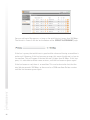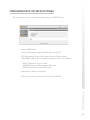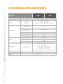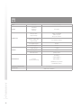
1
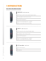
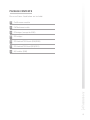
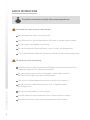
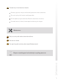
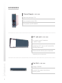
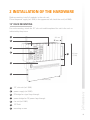
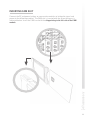
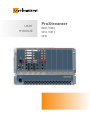
user manual ProStreamer 5202 / 5203 5210 / 5211 5230 No part of this manual may be copied, reproduced, transmitted, transcribed or translated into any language without permission. Unitron reserves the right to change the specifications of the hardware and software described in these manuals at any time. Unitron can not be held liable for any damages resulting from the use of this product. Specifications are subject to change without notice. 09/11 © Unitron - Frankrijklaan 27 - B-8970 Poperinge - Belgium T +32 57 33 33 63 F +32 57 33 45 24 email [email protected] www.johansson.be - www.unitrongroup.com 2 CONTENTS 1INTRODUCTION the ProStreamer range............................................................................................................ 4 package contents..................................................................................................................... 5 safety instructions.................................................................................................................... 6 accessories............................................................................................................................... 8 2 INSTALLATION OF THE HARDWARE 19” rack mounting..................................................................................................................... 9. wall mounting.......................................................................................................................... 10. inserting CAM slot.................................................................................................................. 11. module overview..................................................................................................................... 12 3WEBGUI setting the name of the device............................................................................................. 14 logging into the device........................................................................................................... 15 general configuration............................................................................................................. 16 global.................................................................................................................................... 16 export configuration.......................................................................................................... 16 factory reset........................................................................................................................ 17 firmware upgrade............................................................................................................... 17 configuration of the input...................................................................................................... 18 DVB-S2 input: 5202/5203.................................................................................................... 18 configuration of the output.................................................................................................... 21 configuration of the MPEG setting....................................................................................... 25 4 TECHNICAL SPECIFICATIONS 5202/5203 DVB-S2................................................................................................................... 26 5210/5211 DVB-T..................................................................................................................... 27 5230 A/V.................................................................................................................................... 28 5 CONDITIONS OF WARRANTY......................................................................................... 29 6 UHF FREQUENCY TABLE................................................................................................... 30 7 POWER CONVERSION TABLE......................................................................................... 31 3 1INTRODUCTION THE PROSTREAMER RANGE DVB-S(2) » REF. 5202, 5203 4 SAT inputs with 4 active loop-through outputs 4 transponders over 4 tuner matrix up to 16 FTA programs up to 12 encoded programs: ref. 5203 (with associated multiservice CAM) DVB-T » REF. 5210, 5211 1 RF input with active loop-through output 4 multiplexes over 4 tuner matrix up to 16 FTA programs up to 12 encoded programs: ref. 5211 (with associated multiservice CAM) A/V encoder » REF. 5230 4 A/V stereo inputs 4 programs 4 PACKAGE CONTENTS Be sure all items listed below are included: 1 ProStreamer module 2 CAT6 ethernet cable 4 RF bridges (except for 5230) 2 DC bridges 4 DC blocked 75 Ω loads (5202/5203) 1 DC blocked 75 Ω load (5210/5211) 4 A/V cables (5230) 5 SAFETY INSTRUCTIONS Read these instructions carefully before connecting the unit To prevent fire, short circuit or shock hazard: Do not expose the unit to rain or moisture. Install the unit in a dry location without infiltration or condensation of water. Do not expose it to dripping or splashing. Do not place objects filled with liquids, such as vases, on the apparatus. If any liquid should accidentally fall into the cabinet, disconnect the power plug. To avoid any risk of overheating: Install the unit in a well aery location and keep a minimum distance of 15 cm around the apparatus for sufficient ventilation. Do not place any items such as newspapers, table-cloths, curtains,… on the unit that might cover the ventilation holes. The unit must not be exposed to any source of heat (sun, heater,...). Do not place any naked flame sources, such as lighted candles, on the apparatus. 6 Do not install the product in a dusty place. Use the apparatus only in moderate climats (not in tropical climates). Respect the minimum and maximum temperature specifications. To avoid any risk of electrical shocks: Connect apparatus only to socket with protective earth connection. The mains plug shall remain readily operable. Pull out power plug to make the different connections of cables. To avoid electrical shock, do not open the housing of adapter. Maintenance Only use a dry soft cloth to clean the cabinet. Do not use solvent. For repairing and servicing refer to qualified personnel. Dispose according your local authority’s recycling processes 7 ACCESSORIES Power Supply » REF. 5050 operating voltage: 15 V max. output current: 10 A can power up to 9 modules 19” sub-rack » REF. 5060 can contain up to 9 modules* + power supply mounting in 19” rack or wall-mountable (bindings delivered) delivered with 8 blank plates mounted * depending on the configuration Fan Unit » REF. 5062 voltage: 230 VAC essential for proper functioning of the system 8 2INSTALLATION OF THE HARDWARE Before mounting, install all modules in the sub-rack. Place the power supply (ref. 5050) in the uppermost left slot of the rack (ref.5060). 19” RACK MOUNTING For rack mounting, attach the 19” sub-rack and the optional fan-unit in the rack as indicated by the picture. 1 231 mm 2 3 4 7 312 mm (7 RU) 5 6 484 mm (19”) 1 19” sub-rack (ref. 5060) 2 power supply (ref. 5050) 3 RF bridge for signal loop-through 4 power bridge for DC power loop-through 5 fan unit (ref. 5062) 6 19” Rack 7 mounting screws 9 WALL MOUNTING When mounting the headend to a wall, attach the fan-unit to the sub-rack with the delivered bindings. Attach the mounting brackets on the back of the sub-rack for the mural mounting. 1 231 mm 2 3 4 9 5 6 7 8 484 mm 1 19” sub-rack (ref. 5060) 2 power supply (ref. 5050) 3 RF bridge for signal loop-through 4 power bridge for DC power loop-through 5 wall mounting holes 6 mounting brackets 7 bindings for attaching fan unit to the sub-rack 8 fan unit (ref. 5062) 9 mounting screws 10 312 mm (7 RU) INSERTING CAM SLOT Connect the RF and power bridges on consecutive modules to bridge the signal and power to the following modules. The CAM slot is inserted with the pit on the top as is indicated below. Insert the CAM card with the chip pointing to the left side of the CAM module. 11 MODULE OVERVIEW 5202/5203 5230 9 9 a b c d e f 1 10 1 10 2 11 2 11 3 12 3 12 4 13 4 13 5 14 5 14 6 15 6 15 b 7 8 3 4 5 6 7 8 9 10 11 12 13 14 15 16 1 2 12 a 7 16 SAT input 1 (DiSEqC) a tuner 1 lock LED SAT input 2 (DiSEqC) b tuner 2 lock LED SAT input 3 (DiSEqC) c tuner 3 lock LED SAT input 4 (DiSEqC) d tuner 4 lock LED e power indication LED +15 VDC input f alarm indication LED GND input RJ-45 control port RJ-45 streaming port mounting screws SAT output 1 for loop-through to next module SAT output 2 for loop-through to next module SAT output 3 for loop-through to next module SAT output 4 for loop-through to next module +15 VDC output for loop-through GND output for loop-through CI slot (5303S/T/Q only) 8 3 4 5 6 7 8 9 10 11 12 13 14 15 a b 1 2 CVBS IN 1 (Video IN 1) CVBS IN 2 (Video IN 2) CVBS IN 3 (Video IN 3) CVBS IN 4 (Video IN 4) +15 VDC input GND input RJ-45 control port RJ-45 streaming port mounting screws stereo audio IN 1 stereo audio IN 2 stereo audio IN 3 stereo audio IN 4 +15 VDC output for loop-through GND output for loop-through power indication LED alarm indication LED 5210/5211 6 a 1 7 2 8 3 9 b c d e f 4 5 Terrestrial input +15 VDC input GND input RJ-45 control port RJ-45 streaming port mounting screws terrestrial output for loop-through to next module 8 +15 VDC output for loop-through 9 GND output for loop-through 10 CI slot (5211 only) 3 4 5 6 7 1 2 10 c d e f a b tuner 1 lock LED tuner 2 lock LED tuner 3 lock LED tuner 4 lock LED power indication LED alarm indication LED 13 3WEBGUI SETTING THE NAME OF THE DEVICE When first connecting the modules, be sure to follow this exact procedure! •Connect the first module in the rack with your PC, using an RJ-45 Ethernet cable (without using a switch!). •Open a browser and surf to START •You will now enter the webGui. Go to the Configuration Global menu: •Change the name START to another name. Be sure to choose a logical name and don’t forget this name! This name is the only way to connect to the module later on! It’s advisable to print this name, and label the devices. •After you press APPLY, the module will restart. This will take about 25 seconds. Afterwards, you can surf to the new name you just entered, to connect to the module. •Repeat this procedure with the next modules (1 at a time). •When all modules have a new name, you can connect all modules to the same network. The modules will now get a new IP address, but you can connect by surf- ing to the right name (the unique name you gave the module in the previous steps). 14 LOGGING IN TO THE DEVICE Open your network browser, and surf to the name of the module. You will now log in to the module. After logging in, the Summary window appears. status ‘LED’ On this screen, you see all the services, streamed by this module. The type of module, the status and the language are visible on every screen. In the picture above, the status ‘LED’ is green, indicating that there are no alarms. The alarm status is shown when you move over the status ‘LED’ with your mouse. 15 GENERAL CONFIGURATION GLOBAL Here you can configure the hostname of the module. This name can be used to access the module by simply typing it into your browser as the address and surf to it. This is more convenient than using the IP address. Just enter ‘http://hostname’ into your favorite browser (not case sensitive) and press enter: EXPORT CONFIGURATION The configuration can be exported as an .xml-file. Press DOWNLOAD to save the .xml-file. 16 FACTORY RESET All settings can be reset to default by means of a factory reset. FIRMWARE UPGRADE To upgrade the firmware of the device, click the Firmware upgrade menu item. Click on the BROWSE button, and open the upgrade file. Click UPLOAD to send the file to the device, and click START FIRMWARE to install the new firmware on the device. 17 CONFIGURATION OF THE INPUT DVB-S2 INPUT: 5202/5203 Go to the LNB Settings menu to configure the 4 LNB inputs. • Input: Sequence number of the input (also indicated on the front of the actual module) • Label: custom label for each input (e.g. V low, or ASTRA 19.2 V Low,…) • Voltage: The LNB voltage to select the polarization 13V: Vertical polarization 18V: Horizontal polarization • Tone: LNB tone to select low/high band ON: high band OFF: low band • DiSEqC®: control of a DiSEqC® switch (A/B/C/D) • Band: Satellite band Ku-band: common in Europe C-band: mostly used in the USA • Ext. Voltage: Add 1V to the LNB voltage to compensate the cable losses for long coaxial cables. Press APPLY to confirm the parameters. 18 Go to the TUNER menu to configure the tuner frequency. The modules have 4 independent tuners, which can be assigned to every input, thanks to a built-in multiswitch. • • • Input: One of the 4 labels configured in the previous step. This selects the satellite input. Frequency: Transponder frequency Baud rate [kBaud] Press APPLY to confirm the parameters. The module will now set the tuner to this frequency. Wait until the correct parameters are loaded. 19 When the tuner is able to lock on the frequency, the list of services from this transponder will be shown. The status of the tuner is shown. • Status: Green: tuner locked Red: tuner unlocked • Level: input signal level [dBm] • BER: Bit Error Rate • SNR: Signal to Noise Ratio [dB] The table ‘Available services’ shows all the services found in the transponder. • Type: Type of data TV service radio service locked service (encoded) unlocked service (decoded) • Name: Service name • SID: Service Identifier (unique ID for a service) 20 CONFIGURATION OF THE OUTPUT Navigate to the IP SETTINGS menu to configure the IP addresses at the output. • Channel: The number of the channel • Multicast address: Multicast IP address of the 16 streams. These multicast addresses will be needed to receive the streams on a PC/TV. • UDP port: UDP port number • VLAN: turn VLAN ON/OFF • PCP: Priority Code Point: a 3-bit field which refers to the IEEE 802.1p priority. It indicates the frame priority level. Values are from 0 (best effort) to 7 (highest); 1 represents the lowest priority. These values can be used to prioritize different classes of traffic (voice, video, data, etc) • VID: VLAN Identifier: a 12-bit field specifying the VLAN to which the frame belongs. 21 Navigate to the SERVICE ASSIGNMENT menu to configure the streams. Every Prostreamer module (except for the 5230) can stream up to 16 services. • • • • • • • Multicast address: IP address of the stream Port: UDP port of the application Name: Name of the service SID: Service ID: Unique number, which identifies the service ON: Check this box to enable the streaming of this service, uncheck to stop the streaming. CAM: Check this box to pass this stream through the CAM slot for decryption. Icons: add a new program to the list of services update the current service, this icon will become active if some setting has changed delete the service from the list, pressing this icon will remove the program permanently (you can add it again) 22 Press the button to add a new service. A list of available services (from all 4 tuners) will appear on the screen. Click on the service to be added and wait until the service is loaded into the list. The list will be refreshed and the added service will appear. 23 You can add up to 16 programs, as long as the total bitrate is lower than 100 Mbps. The bitrate is shown in the bar on the bottom of the SERVICE ASSIGNMENT page: If the bar is green, the total bitrate is good and the chance of having an overflow is quite small. However, if this bar becomes orange, this means the bitrate is close to an overflow. This will happen if the total bitrate is higher than 85 Mbps. If this happens, it is advisable to delete some services, until the bar becomes green again. If the bar becomes red, there is an overflow. This can be due to the fact that the total bitrate exceeds 100 Mbps, or there can be a CAM overflow. Delete services until the bar becomes green again. 24 CONFIGURATION OF THE MPEG SETTINGS This menu item is only visible with modules having a DVB-S2 input. • Forward EPG tables: Forward Electronic Program Guide tables to the TV’s • CAS forwarding: Forward the Control Access System tables (CAT, EMM, ECM) to descramble the programs with a set-top box CAT: Conditional Access Table EMM: Entitlement Management Message ECM: Entitlement Control Message • Block others: Block private data • PID share: Enable sharing of the PES, PCR and ECM 25 4 TECHNICAL SPECIFICATIONS DVB-S2 5202 5203 INPUT interface 4 x QPSK / 8PSK OUTPUT standard protocols capacity IEEE 802.3 10/100 Base-T Multicast IP/UDP up to 16 simultaneous streams (up to 100 Mbps) RF input with loop-through 8 x female F power supply with loop-through 4 x ‘banana socket’ management port RJ-45 CONNECTORS streaming port PCMCIA CAM slot RJ-45 no supply voltage GENERAL PERFORMANCE OPERATING TEMPERATURE DIMENSIONS 26 consumption yes +15 VDC 0.6 A 0.8 A LED indications 4x lock status, power, alarm transport stream processing de-multiplexing of up to 4 transponders PSI/SI parsing PID filtering/remapping capability regeneration of PAT/PMT tables EMM/ECM pass-through IP/UDP encapsulation of up to 16 MPEG streams 0 to +40°C 5RU x 8TE x 195 mm DVB-T 5210 5211 INPUT interface 4 x COFDM OUTPUT standard protocols capacity IEEE 802.3 10/100 Base-T Multicast IP/UDP up to 16 simultaneous streams (up to 100 Mbps) RF input with loop-through 2 x female F power supply with loop-through 4 x ‘banana socket’ management port RJ-45 CONNECTORS streaming port PCMCIA CAM slot RJ-45 no supply voltage GENERAL PERFORMANCE OPERATING TEMPERATURE DIMENSIONS consumption yes +15 VDC 0.5 A 0.7 A LED indications 4x lock status, power, alarm transport stream processing de-multiplexing of up to 4 multiplexes PSI/SI parsing PID filtering/remapping capability regeneration of PAT/PMT tables EMM/ECM pass-through IP/UDP encapsulation of up to 16 MPEG streams 0 to +40°C 5RU x 8TE x 195 mm 27 5230 A/V INPUT interface 4 x A / V (CVBS) OUTPUT standard protocols capacity 4 streams RF input with loop-through video: 4 x CINCH audio: 4 x jack Ø 3,5 mm stereo power supply with loop-through 4 x ‘banana socket’ management port RJ-45 streaming port RJ-45 supply voltage +15 VDC CONNECTORS GENERAL PERFORMANCE OPERATING TEMPERATURE DIMENSIONS 28 consumption 0.65 A LED indications power, alarm transport stream processing encoding: video: MPEG-2 audio: MPEG-1 IP/UDP encapsulation of 4 MPEG streams 0 to +40°C 5RU x 8TE x 195 mm 5 CONDITIONS OF WARRANTY PERIOD OF WARRANTY Unitron N.V. warrants the product as being free from defects in material and workmanship for a period of 24 months starting from the date of production indicated on it. See note below. If during this period of warranty the product proves defective, under normal use, due to defective materials or workmanship, Unitron N.V, at its sole option, will repair or replace the product. Return the product to your local dealer for reparation. THE WARRANTY IS APPLIED ONLY FOR DEFECTS IN MATERIAL AND WORKMANSHIP AND DOES NOT COVER DAMAGE RESULTING FROM •Misuse or use of the product out of its specifications. •Installation or use in a manner inconsistent with the technical or safety standards in force in the country where the product is used. •Use of non-suitable accessories (power supply, adapters ...). •Installation in a defect system. •External cause beyond the control of Unitron N.V. such as drop, accidents, lightning, water, fire, improper ventilation… THE WARRANTY IS NOT APPLIED IF •Production date or serial number on the product is illegible, altered, deleted or removed. •The product has been opened or repaired by a non-authorised person. NOTE Date of production is MMYY format, example 0411 = April 2011. For the serial number barcodes, the date corresponds to the 4 first numbers. 29 6 UHF FREQUENCY TABLE TV band Channel Frequency MHz IV 21 22 23 24 25 26 27 28 29 30 31 32 33 34 35 36 37 38 39 40 41 42 43 44 45 46 47 48 49 50 51 52 53 54 55 56 57 58 59 60 61 62 63 64 65 66 67 68 69 470-478 478-486 486-494 494-502 502-510 510-518 518-526 526-534 534-542 542-550 550-558 558-566 566-574 574-582 582-590 590-598 598-606 606-614 614-622 622-630 630-638 638-646 646-654 654-662 662-670 670-678 678-686 686-694 694-702 702-710 710-718 718-726 726-734 734-742 742-750 750-758 758-766 766-774 774-782 782-790 790-798 798-806 806-814 814-822 822-830 830-838 838-846 846-854 854-862 V 30 7 POWER CONVERSION TABLE μV 75 Ω dBμV dBm 1 1.5 2 2.5 3 3.5 4 4.5 5 6 7 8 9 10 15 20 25 30 35 40 45 50 60 70 80 90 100 150 200 250 300 350 400 450 500 600 700 800 900 0 3.5 6 8.0 9.5 11 12 13 14 15.5 17 18 19 20 23.5 26 28 29.5 31 32 33 34 35.5 37 38 39 40 43.5 46 48 49.5 51 52 53 54 55.5 57 58 59 -109 -105.5 -103 -101 -99.5 -98 -97 -96 -95 -93.5 -92 -91 -90 -89 -85.5 -83 -81 -79.5 -78 -77 -76 -75 -73.5 -72 -71 -70 -69 -66.5 -63 -61 -59.5 -58 -57 -56 -55 -53.5 -52 -51 -50 mV 75 Ω 1 1.5 2 2.5 3 3.5 4 4.5 5 6 7 8 9 10 15 20 25 30 35 40 45 50 60 70 80 90 100 150 200 250 300 350 400 450 500 600 700 800 900 1000 dBμV dBm V 75 Ω dBμV dBm 60 63.5 66 68 69.5 71 72 73 74 75.5 77 78 79 80 83.5 86 88 89.5 91 92 93 94 95.5 97 98 99 100 103.5 106 108 109.5 111 112 113 114 115.5 117 118 119 120 -49 -45.5 -43 -41 -39.5 -38 -37 -36 -35 -33.5 -32 -31 -30 -29 -25.5 -23 -21 -19.5 -18 -17 -16 -15 -13.5 -12 -11 -10 -9 -5.5 -3 -1 +0.5 +2 +3 +4 +5 +6.5 +8 +9 +10 +11 1 1.5 2 2.5 3 3.5 4 4.5 5 6 7 8 9 10 120 123.5 126 128 129.5 131 132 133 134 135.5 137 138 139 140 +11 +14.5 +17 +19 +20.5 +22 +23 +24 +25 +26.5 +28 +29 +30 +31 31 www.unitrongroup.com UNITRON NV Frankrijklaan 27 B-8970 Poperinge Belgium T +32 57 33 33 63 F +32 57 33 45 24 [email protected] www.johansson.be