1
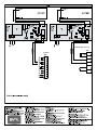
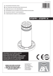
027908
D811348_03 31-07-12
8
197030
STOPPY BAT
INSTALLATION AND USER’S MANUAL
BUFFER BATTERY KIT
Attenzione! Leggere attentamente le “Avvertenze” all’interno! Caution! Read “Warnings” inside carefully! Attention! Veuillez lire attentivement les Avertissements qui se trouvent à l’intérieur! Achtung! Bitte lesen Sie
aufmerksam die „Hinweise“ im Inneren! ¡Atención¡ Leer atentamente las “Advertencias” en el interior! Let op! Lees de “Waarschuwingen” aan de binnenkant zorgvuldig!
INSTALLATION MANUAL
1) GENERAL OUTLINE
STOPPY-BAT mod. buffer battery kit.
The use of this accessory prevents the anti-transiting bollard from lowering
spontaneously when the mains power supply is off.
NOTE: When the mains power supply is off, no opening or closing manoeuvres can be carried out.
The kit includes:
• 1 buffer battery
• 1 battery-charger board
• Fitting instruction manual.
2) SPECIFICATIONS FOR STOPPY-BAT BOARD AND BATTERIES
Power supply voltage: ................................................. 230V~ ±10% 50Hz*
Max absorbed power: ........................................................................ 12 VA
Battery: .................................................................................... 12V (7,2Ah)
Charge voltage: ............................................................................... 13.8V=
Max charge current: ........................................................................... 10.5A
Service with power supply off ............ : from 6h (1 Stoppy) to 2h (4Stoppy)
(* other voltages available on request)
3) FITTING
personnel.
- Disconnect the mains power supply.
- Carry out the connections as shown in the diagram (Fig.1).
Connect the board power supply to the same power supply line for the
Perseo control panel.
2 - STOPPY-BAT - Ver. 03
Use two wires having a minimum cross section of 1 sq mm (maximum length
5 m) to connect outputs:
V. OUT+
to terminal 13 on the Perseo panel
V. OUTto terminal 14 on the Perseo panel.
The battery poles are to be connected to the appropriate Faston terminals.
Once a year, check that the anti-transiting bollard and buffer battery operate
correctly.
A value of about 13.8V= must be obtained after disconnecting the buffer battery
and measuring the voltage present at the ends of the Faston terminals.
In the case where the value needs to be regulated, operate the VR1 trimmer.
For battery disposal, refer to the current standards.
The descriptions and illustrations contained in the present manual are
not binding. The Company reserves the right to make any alterations
deemed appropriate for the technical, manufacturing and commercial
improvementof theproduct,whileleaving theessentialproductfeatures
unchanged, at any time and without undertaking to update the pres
ent publication.
-
D811348_03
ENGLISH
PERSEO CBD 230.P SD
J10
PERSEO
EF
SHIELD
ANT
CN2