1
1
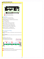
■ Table of Contents
Title
■ Table of Contents
■ For Safe Operation
■ Getting Started
●Transmitter Assembly
●Transmitter Dismantling
■ Names of Parts
●ET Keys (1-5) and BT Button (1)
●Steering Wheel Adjustment
●Throttle Trigger Adjustment
●Throttle Trigger Position Adjustment
●ICS Port
●Headphone Jack
●Colored Grip and Pad Replacement
●Unit Connector
●Charger Jack
●Power Switch
■ Preparations
●Battery Installation
●Battery Level Warning
●Operation Alarm
●Battery Pack(Under Development)
●Countermeasures Against Noise
●Receiver Installation
●Pairing
●Fail safe Setting ■ Procedures Prior to Operation
●Trim and Sub Trim Operation
■ Display and Control Method
●Basic Operations to Change Settings
●Startup Screen and Initial Screen
■Function Reference
●Main Menu
Model Menu(Model)
Model Select(MDL-Select)
Model Name(MDL-Name)
Model Copy(MDL-Copy)
Model Reset(MDL-Reset)
Steering Menu(Steering)
Steering Trim(ST-Trim)
Steering Travel(ST-Travel)
Steering Balance(ST-Balance)
Steering Sub Trim(ST-SubTrim)
Steering Trim Rate(TrimRate)
Steering Turn Speed(TurnSpeed)
Steering Return Speed(RetnSpeed)
Steering Punch(ST-Punch)
Steering Curve(ST-Curve)
Steering Reverse(ST-Reverse)
Travel Override(Travel Override)
Throttle Menu(Throttle)
Throttle Trim(TH-Trim)
Throttle High Point(TH-Point)
Throttle Brake(TH-Brake)
Throttle Sub Trim(TH-SubTrim)
Throttle Trim Rate(TH-TrimRate)
Throttle Turn Speed(TH-TurnSpeed)
Throttle Return Speed(TH-ReturnSpeed)
Throttle Punch(TH-Punch)
Throttle Curve(TH-Curve)
Throttle Reverse(TH-Reverce)
Throttle Drag Brake(TH-DragBrake)
Brake Override(Brake Override)
Throttle ABS(TH-ABS)
Throttle Acceleration(TH-Accel)
Throttle Auto-Start(TH-AutoStart)
Idle Up(IdleUp)
Click the page number to jump to that page.
Page
2
3
5
5
5
6
7
7
7
7
7
7
8
8
8
8
9
9
9
9
9
10
11
11
12
13
14
15
15
16
17
17
17
18
18
19
19
20
20
20
21
21
21
22
22
24
23
24
24
25
25
25
26
26
26
27
28
29
29
30
30
30
31
32
33
33
Title
3CH/4CH Menu(3/4ch Menu)
Control Menu(Control Menu)
Control Mode(Control Mode)
2WAY(2WAY)
3WAY(3WAY)
5WAY(5WAY)
ANALOG(ANALOG)
4WS Mixing(4WSMix)
4WS Mixing Mode(4WSMix MODE)
4WS Mixing Left(4WSMix LEFT)
4WS Mixing Center(4WSMix CENTER)
4WS Mixing Right(4WSMix RIGHT)
4WS Mixing Travel(4WSMix TRAVEL)
4WS Mixing Reverse(4WSMix REVERCE)
4WS Mixing Key(4WSMix KEY)
Amp Mixing(AMP Mix)
Amp Mixing Mode(AMPMix MODE)
Amp Mixing Throttle Hold(AMPMix HOLD)
Amp Mixing High Point(AMPMix HIPOINT)
Amp Mixing Brake(AMPMix BRAKE)
Amp Mixing Reverse(AMPMix REVERSE)
Amp Mixing Trim(AMPMix TRIM)
Amp Mixing ET Mode Setting(AMPMix ET MODE SET)
Amp Mixing Key(AMPMix KEY)
Throttle Mixing(T-Mix)
Throttle Mixing Brake(T-Mix BRAKE)
Throttle Mixing Center(T-Mix CENTER)
Throttle Mixing High Point(T-Mix HIPOINT)
Throttle Mixing Reverse(T-Mix REVERCE)
Throttle Mixing Curve(T-Mix CURVE)
Throttle Mixing Delay(T-Mix DELAY)
Throttle Mixing Steering(T-Mix STEER)
Throttle Mixing On/Off(T-Mix ON/OFF)
Throttle Mixing Key(T-Mix KEY)
Quick Setup(QuickSetup)
Timer Menu(Timer Menu)
Stopwatch(StopWatch)
Countdown Timer(DownTimer)
Lap History(LapHistory)
Function Menu(Function Menu)
Monitor(Monitor)
LED Color(LEDcolor)
LCD Backlight(BackLight)
LCD Contrast(Contrast)
Sound Volume(SoundVol)
Buzzer(Buzzer)
Key Repeat(KeyRepeat)
System Menu(System Menu)
Response(Response)
Setup(Setup)
Direct Switch(DirectBT)
Adjust VR (ST)(SteeringAjustVR)
Adjust VR (TH)(ThrottleAjustVR)
Operation Timer(OP-Timer)
2.4G Band(2.4GBand)
Power Management(POWER MANAGEMENT)
All Reset(AllReset)
ICS(ICS)
Approval
●Warning Display
Battery Level Warning
■ Glossary
■ Specifications
2
Page
34
34
34
34
35
35
36
37
37
37
37
38
38
38
38
39
39
40
40
40
41
41
41
41
42
42
42
43
43
43
43
44
44
44
45
46
46
47
47
48
48
48
48
49
49
49
49
50
50
51
51
51
52
52
52
53
53
53
53
54
54
55
58
■ For Safe Operation
Due to the nature of radio controlled models, improper handling may lead to dangerous situations. Therefore please
read the following information carefully in order to ensure safe operation. Please also understand that KO Propo is
not responsible for any injuries or damage which result from noncompliance of these cautions and notices.
Warning! Improper handling/
usage may lead to a high probability of material damage as well as a possibility of
serious personal injury or even death.
Notice! Improper handling/
usage may lead to personal injury or material damage.
●When Installing Components
Warning!
Prohibited matters
Warning!
Enforcement matters
●Make sure metal parts on the model (car chassis/ship hull) do not come into contact
with each other.
※Contact between metal parts may result in noise, which could cause the receiver to
malfunction and lead to an uncontrollable model.
●Do not cut or bundle the antenna cable.
※This may lower the receiver's sensitivity and lead to an uncontrollable model.
●Ensure correct polarity when installing transmitter and receiver batteries.
※Incorrect polarity may damage the product.
●Within Japan, this product is limited to usage with models which operate on the
ground or in the water.
※Do not use for other non-designated purposes.
●Ensure that all connectors (receiver, servo, switch, etc.) are connected securely.
※If connections become loose due to vibrations, it may lead to an uncontrollable model.
●Securely attach receiver with thick double-sided tape and ensure that it does not
make contact with other parts.
※Strong shocks or contact with other parts due to vibrations may lead to an
uncontrollable model.
●Check servo operation to ensure the pushrod is not subject to excessive loads.
※Excessive loads may damage the servo or increase battery power consumption.
●Make sure to use the rubber grommet when attaching the servo and that the servo
does not contact the R/C equipment tray.
※If vibrations affect the servo, it may lead to damage or an uncontrollable model.
●Use in conjunction with genuine official KO Propo products.
※KO Propo is not responsible for any damages or injuries which result from use of this
product in combination with other manufacturer's products.
●Notes for Usage
Warning!
Prohibited matters
Warning!
Enforcement matters
●Do not use when there is thunder.
※It is possible for lightning to strike the antenna.
●Do not use in the rain or in areas where water has accumulated.
※If water enters the product it may lead to an uncontrollable model.
●Do not use in the following locations:
1. Near R/C circuits (within 3km)
2. Near crowds, on streets, or near actual vehicles or ships.
3. Near high-voltage power lines or communication facilities.
※If signal interference, etc. causes an uncontrollable model, a serious accident may
result.
●Do not use when your concentration levels are compromised by tiredness, alcohol,
medication, etc.
※Mistakes in judgment may result in serious accidents.
●Do not allow glow engine fuel or engine exhaust to contact the product.
※These may attack the plastic and damage the product.
●Check to ensure that the selected model memory matches the model to be controlled.
※Using an incorrect memory may lead to an uncontrollable model.
●Make sure to stop the engine (disconnect motor cables) before changing transmitter
settings.
3
Caution!
Prohibited matters
Caution!
Enforcement matters
●Do not touch engine, motor, ESC, etc. immediately after use as they may be hot.
※Doing so may lead to burns.
●When switching on, always turn on the transmitter first, followed by the receiver.
Follow the reverse order when switching off.
※If the wrong order is followed, it may lead to an uncontrollable model.
●Dismantling or modifying the RF Module (internalized in the case of the EX-1) is
prohibited and is punishable by law.
※Doing so may lead to accidents such as short circuits and KO Propo Customer
Service Department may not accept dismantled/modified products for repair.
●Do not use this product in aircraft, hospitals, or near fire alarms or medical equipment.
※This may lead to malfunctions and result in serious accidents. Also, by law you must
cease operation if the product affects other wireless or electrical devices.
●2.4GHz transmitters must be registered with the Japan Radio Control Safety
Association.
※The transmitter which you have purchases is already registered. Products which do
not have proof of registration are illegal.
●Notes After Usage
Warning!
Enforcement matters
Caution!
Enforcement matters
●In the case of an R/C car, make sure to remove the battery pack after driving.
※If the car is switched on accidentally, it may lead to a fire or an uncontrollable model.
●Keep transmitters, batteries, and models away from small children.
※Chemical agents and the items themselves may cause personal injury.
●Remove batteries from transmitter if it will not be used for a considerable time.
※If batteries are left in the transmitter, battery leakage may result in damage.
●Do not store transmitter/receiver in the following conditions:
1. Extremely hot (over 40ºC) or cold (below 10ºC) temperatures.
2. Locations in direct sunlight.
3. Locations with high humidity.
4. Locations subject to vibrations.
5. Locations with lots of dust.
※These conditions may cause the case to deform and damage the product.
●Transmitter Battery Handling and Charging (separately available option)
Danger!
Enforcement matters
Danger!
Enforcement matters
●Never short-circuit the battery connector.
※This may lead to a fire or explosion.
●Do not dispose batteries in fires.
※This is very dangerous and may lead to an explosion.
●Use KO Propo chargers to charge the battery and use the correct current (under 1A).
※Incorrect current may lead to battery damage, overheating, or leakage.
※Other manufacturer's chargers may not have a automatic cutoff function.
●Do not subject the battery to strong shocks.
※This may damage the battery and cause leakage or a short circuit.
●Do not dismantle or modify the battery.
※This may cause dangerous leakage of battery fluids.
●Keep away from water. Do not charge a wet battery.
※This may cause overheating and damage.
●Do not charge alkaline batteries.
※Alkaline and other single-use batteries cannot be recharged. Doing so may lead to fire
and damage.
●Do not use wet hands when plugging in the charger's AC Adapter.
※This may result in electrical shocks.
※If there is battery fluid leakage, avoid contact with eyes as it may result in blindness. If contact
with eyes occur, flush with large amounts of water and seek medical attention immediately.
※When disposing batteries, Ni-Cd, Ni-MH, Li-Po, and Li-Fe batteries should be recycled in order to
help protect the environment.
4
■ Getting Started
[Legend]
P
:Point
:Notice
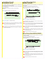
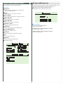
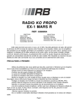
●Transmitter Assembly
●Transmitter Dismantling
Insert the Grip Unit into the Master Unit, then attach the
Steering Unit.
Detach the Steering Unit, then detach the Master Unit.
Remove the connector cover before attaching.
1.
Steering Unit
1.
Master Unit
First detach the
antenna.
Steering Unit Release Button
③
Steering Unit Lock Lever
①
②
Grip Unit
2.
Grip Unit Lock Lever
2.
Steering Unit
Master Unit
3.
Grip Unit Release Button
①
③
Steering Unit Release Button
①
Steering Unit Lock Lever
②
②
If storing the transmitter in dismantled form, please remember to
attach the connector covers.
3.
4.
Tilt Display
(Raised Position)
5
Antenna
(Rotate to loosen)
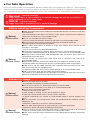
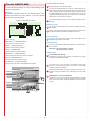
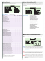
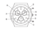
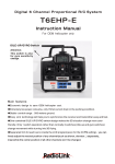
■ Names of Parts
[Side View]
[Front View]
Antenna
Tilt Display
Direct Button
DBT 1-4(p.7)
Jog Dial
Steering Wheel
(p.7)
ET1
(p.7)
Multicolor LED
ET2
ET3
(p.7)
BT1
Dial Guard
(p.7)
Enter Key
(p.7)
Back Key
ET4
Power Switch (p.8)
(p.7)
Steering Unit
Release Button (p.5)
Charger Jack (p.8)
Open the cover
ET5
(p.7)
Trigger Guard
Steering Unit
Lock Lever (p.5)
Throttle Trigger (p.7)
Colored Grip
(p.8)
Colored Pad (p.8)
Guard Bar
[Rear View]
Open the cover
Grip Unit
Release Button (p.5)
ICS Port (p.7)
Grip Unit Lock Lever
(p.5)
Throttle Trigger
Position Adjuster (p.7)
6
Headphone Jack (p.7)
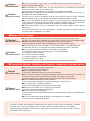
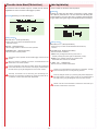
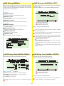
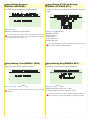
●Throttle Trigger Position Adjustment
●ET Keys (1-5) and BT Button (1)
The position of the throttle trigger may be adjusted to match the
user's hands.
Functions may be assigned to the keys/button.
[How to Adjust]
The possible functions which each key/button may be assigned to
are different.
Loosen two screws on the rear side of the transmitter.
Slide the Throttle Trigger Position Adjuster as desired.
Tighten the loosened screws to secure.
●Steering Wheel Adjustment
Adjust the tension of the steering wheel spring.
Screws
[How to Adjust]
Insert a 1.5mm hex wrench referring to the image below.
Rotate clockwise to increase tension and counterclockwise to
decrease it.
Throttle Trigger
Position Adjuster
Hex Wrench
●ICS Port
This port is used for the ICS USB Adapter HS (sold separately),
which enables the transmitter to connect to a PC. Special
software, which can be downloaded from KO Propo's website,
enables the setting and modification of the transmitter's model
memory from a PC. It also enables numerous model memory
settings to be saved onto a PC. Refer to KO Propo's website
for details on how to use this feature.
( http://www.kopropo.co.jp/sys/ )
Excessive counterclockwise rotation will result in the wheel being
unable to return to neutral position. In this case, rotate clockwise
until the wheel returns to neutral.
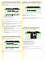
●Throttle Trigger Adjustment
Adjust the position and angle of the brake trigger to your
preferences.
Connect to PC
[How to Adjust]
Loosen the hex screws on the throttle trigger with a 1.5mm
hex wrench.
●Headphone Jack
Freely adjust the brake trigger position.
Attach audio plugs from commercially available headphones,
etc. (sold separately) to the transmitter. This feature helps
users hear the transmitter's operation sounds while in a noisy
pit area.
Tighten the hex screws to secure.
Throttle Trigger
Brake Trigger
Audio Plug
(Sold Separately)
Hex Screws
Ball Joint
The trigger may be loosened due to temperature, strong shocks,
or prolonged use. In this case, cementing the trigger in position is
recommended. If looseness persists, contact KO Propo Customer
Service Department.
Even when headphones are plugged in, sounds will still be emitted
by the transmitter itself. The headphone jack is monaural.
7
●Colored Grip and Pad Replacement
●Charger Jack
Users can choose to install grips and pads of other colors (sold
separately).
A rechargeable battery can be recharged via the charger jack.
[How to Replace]
[How to Recharge]
Confirm that the power switch is in the OFF position. If only
using the Grip Unit, make sure that the connector cover is in
place.
Remove the two screws on each side of the grip to detach the
grip plates, then attach the colored grip and pad.
Screws
Make sure the battery is securely connected. If the
connection is loose, the battery may not charge completely.
Grip Plate
Securely connect the charger plug to the charger jack.
Begin charging using a current of less than 1A.
AC 100V Charger
(Available Soon)
Colored Pad
Colored Grip
Screws
Grip Plate
Make sure the battery box or battery pack is removed before
replacing the colored grip and pad.
Quick Charger (Sold Separately)
The tabs on the colored grip and pad are to be inserted into holes.
Note the direction.
Make sure the power switch is in the OFF position when charging.
If only using the Grip Unit, make sure that the connector cover is in
place. A short circuit may occur if the connector makes contact with
metal and lead to a serious accident. Use a current of less than 1A to
charge. Do not connect/disconnect the battery during charging. Take
note of the charger plug's polarity in order to avoid damage.
Note direction of the of the colored grip and pad.
●Unit Connector
Do not attempt to charge if using alkaline batteries. Doing so
may result in battery leakage or cracking which will damage the
transmitter.
This product may be dismantled and therefore each unit
features their respective connectors. Dirty or damaged
connectors may result in malfunctions, so please handle them
carefully.
[Discharging the Battery Pack]
If using a battery pack, please note that it cannot be discharged via
the charger jack. Remove the battery pack from the transmitter to
discharge it.
Connector Cover
●Power Switch
This product features a safety lock. The Master Unit and Grip
Unit cannot be detached when the Power Switch is in the ON
position. Turn off the transmitter before dismantling.
Power Switch
Do not touch the unit connectors with your fingers. If connectors
become corroded due to grime, they may become inoperable.
If storing the transmitter in dismantled form, please remember
to attach the connector covers. After prolonged use, a black
residue may build up on the connectors. Use cotton swabs dipped
in cleaning alcohol to remove. KO Propo's Customer Service
Department also handles transmitter maintenance.
8
■ Preparations
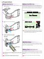
●Battery Installation
1.
●Battery Level Warning
The power source used may be set in Power Management. A
warning will be displayed and an alarm will sound when low
battery voltage is detected. When you see this warning, stop
your model in a safe area and install new transmitter batteries.
Press the tab on the bottom of the transmitter to open
battery box cover.
[Warning Display on Startup]
①
②
Battery Box Cover
2.
[Warning Display During Use]
Remove the lock to pull out battery
box.
①
Operation of the transmitter's jog dial, buttons, or levers will
temporarily disable the low-voltage warning sound. The warning
will be displayed again after a certain amount of time has passed.
Voltage value is not display and display "Low".
②
3.
Install four R03/AAA/UM4 alkaline
batteries while noting their polarity,
then replace
battery box.
●Operation Alarm
An alarm will sound after 3 minutes of transmitter idleness.
Operating the steering wheel, ET Keys, BT Button, Direct
Buttons, etc. will disable the alarm.
R03/AAA/UM4
Batteries (4pcs.)
●Battery Pack(Under Development)
Battery Box
A rechargeable battery pack specific to the EX-1 is under
development. An announcement will be made on the KO
Propo website when it is ready for release. Thank you for your
patience.
Use batteries which have adequate remaining capacity. Weak
batteries mean lower transmitting power and may result in
malfunctions.
Do not install Ni-Cd or Ni-MH batteries in the battery box.
(These may cause the battery connectors to corrode.)
Make sure to fully charge the battery pack before installing it.
9
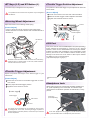
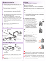
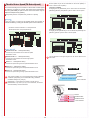
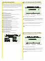
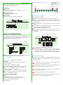
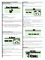
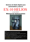
●Countermeasures Against Noise
Keep antenna cable away from all sources of noise!
Noise is generated in any area where a large amount of
electric current is flowing. Position the receiver and
antenna cable as far away from the motor, battery, ESC,
and their associated cables as possible. (Metal or carbon
fiber chassis components will also conduct electricity
and generate noise.)
Since R/C models are controlled via radio signals, taking
appropriate measures against noise generated by
on-board equipment is of utmost importance. Take
adequate measures against noise so that your machine
can fully realize your driving potential.
Carbon Fiber Chassis
Battery Pack
isisee
NNoo
see
oisi
NNo
N
Noo
iiss
ee
Receiver
Motor
isisee
NNoo
Silicon Cables
isisee
NNoo
ESC
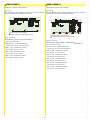
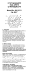
● Receiver Installation on a Carbon Fiber Chassis
When installing the receiver to the chassis or R/C
equipment deck/tray, use two or more pieces of thick
double-sided tape to raise the receiver off the chassis
surface. By increasing the separation between the
receiver and the noise-generating carbon-fiber chassis
components, the effects of noise can be decreased.
※Install the receiver so that its LEDs are visible.
see
oisi
NNo
isisee
NNoo
Double-Sided Tape
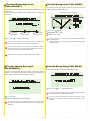
● Antenna Installation
Raise the antenna cable vertically from as high a position as possible. Insert the antenna cable into the antenna
pipe so that the tip of the antenna aligns with the end of the pipe. Make the length of cable which runs between
the receiver and the pipe as short as possible and position the antenna holder as close to the receiver as
possible. Position the antenna cable away from sources of noise such as the chassis and R/C equipment
deck/tray. Use an antenna pipe and antenna mount that are made from plastic, since metal parts will conduct
noise.
Signal Receiving Section
N
Noo
iisse
e
Antenna Cable
※Do not bend or cut the antenna cable.
(This may break the antenna wire and deteriorate its
performance.)
Plastic Antenna Pipe
Piano Wire
Aluminum Antenna Holder
isisee
NNoo
Soldered Lug Plate
Aluminum Antenna Holder
isisee
NNoo
Plastic Antenna Pipe
Plastic Antenna Holder
(Acceptable with FRP
or plastic chassis)
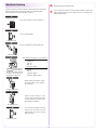
● Installing Onto a Glow Engine Car
Engine vibrations may damage the receiver. Make sure to attach a
grommet (receiver holder) to reduce the effects of such vibrations. Do
not attach the receiver directly to the chassis or R/C equipment
deck/tray with double-sided tape. Also position the receiver so that it
does not contact the heat and exhaust of the engine and muffler.
※Install the receiver so that its LEDs are visible.
10
Grommet
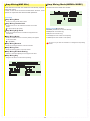
●Receiver Installation
●Pairing
1.
1. Preparing the Transmitter
Install the receiver, servo, and ESC (in the case of an
electric car) onto your machine and connect them. Install
the receiver while taking noise into consideration (p.10).
Switch on the transmitter.
Press the ENTER key at the startup screen. (Main Menu
display)
Carefully read the instructions included with the servo and
ESC before installing and using them.
2.
3.
Use the jog dial to move the cursor to [System], then press
the ENTER key.
Install batteries into the transmitter's battery box (p.9).
In the case of an electric car, install battery pack. In the
case of a glow engine car, install battery for receiver.
Move the cursor to [2.4Gband] on the System Menu
screen, then press the ENTER key.
Move the cursor to (START) on the 2.4Gband screen, then
press the ENTER key.
Images of the transmitter and receiver will display and the
arrow flow can be checked. (In this state, the transmitter is
transmitting the pairing signal.)
For 2.4GHz systems, conduct pairing of the transmitter
and receiver (see right column).
In order for the receiver to operate, it must store the
transmitter's unique ID in its memory in a process called
“pairing.” Even if a single transmitter is used to control
multiple receivers, each receiver must go through the
pairing process with the transmitter before being used for
the first time.
4.
Adjust steering(p.20)and throttle/braking(p.25).
5.
Set the Fail-Safe Function.
2. Preparing the Receiver
Connect the receiver power source
while pressing the setup button.
BATT
Check that the receiver's LED has lit
up, then release the setup button.
Check that the receiver's LED lights up
again (indicating pairing completion)
When pairing is complete, pressing
the ENTER key on the transmitter
will return the screen to the previous
[2.4Gband] menu.
●For an Electric Car
Switch off the receiver, then switch it
back on again for normal operations.
●Battery Pack
(Sold Separately)
The preparations below are to be carried
out following the pairing procedure.
Lit LED
Preparations for Operation
●Motor
(Sold Separately)
●Steering Servo (CH1)
(Sold Separately)
Switch off the receiver.
3.
●ESC (CH2)
(Sold Separately)
●Receiver (KR-411FH)
●For a Glow Engine Car
Press the ENTER key on the
transmitter, then press the BACK key
twice to return to the initial screen.
Switch on the receiver and check
that the receiver LED is lit. If the LED
flashes, the receiver is not getting
the transmitter signal and the pairing
procedure should be repeated.
Lit LED
●Steering Servo (CH2)
(Sold Separately)
Flashing LED
●Steering Servo (CH1)
(Sold Separately)
●Receiver
(KR-411FH)
●Battery for Receiver
(Sold Separately)
P
See p.52 regarding the 2.4Gband menu.
During this process, your car may become uncontrollable if the
ESC has not been adjusted. As a precaution, set your car so that its
wheels do not touch the ground.
This transmitter is only compatible with digital servos. Correct
operation is not possible when used with analog servos.
Pairing procedures may not go smoothly if there are wireless LAN,
microwave ovens, or other users conducting pairing procedures
nearby. In this case, move some distance away or wait a while
before attempting the pairing procedure again.
For items which are not included in this product, please refer to the
KO Propo website for a list of compatible products. (http://www.
kopropo.co.jp)
11
●Fail-Safe Setting
Please be sure to set the fail-safe.
Fail-safe is when the receiver loses the radio signal of the transmitter
and the function keeps channel 2 (throttle) in an optional position.
The configuration is usually full brake or neutral.
If you change the position of the fail-safe operation, please set
again. We recommend to set it again even if you modify the car
engine brake linkage.
This function works for only 2nd channel.
4
3
2
1
B
Turn on the transmitter.
Transmitter ON
Turn on the receiver and verify operation.
Receiver ON
Recommended positions are the following :
Full brake
Hold the throttle
to the position
On the transmitter, hold the
throttle to the position you
would like it to be set to.
Neutral
Full Brake
●GP car
●EP car
(forward / Brake)
Neutral
●EP car
(forward / Back)
(forward / Brake / Back)
While holding the position, press
the setup button on the receiver
for 3 seconds.
Press for 3 seconds
Hold the setup button on the
receiver until the LED light goes
off and release the button. Failsafe setting is complete.
LED light goes off
Turn off the transmitter. And the
device that connected into 2nd
Channel will move to the position
that you set up.
Transmitter OFF
12
■ Procedures Prior to Operation
1.Switching On
After ensuring that it is safe to do so, switch on the transmitter followed by the receiver.
This product uses the FHSS transmission system, which switches between frequencies in the2.4GHz range at a high speed.
FRANCE Mode needs to be selected if this product is to be used in France, while other countries should use GENERAL Mode.
(If the mode is switched between GENERAL and FRANCE, pairing procedure must be done with the receiver again.)
2.Model Confirmation
Confirm the model which will be used.
3.Checking Movements
With the model's wheels lifted off the ground, operate transmitter to check for proper
movement. While driving, use steering and throttle trims to make fine adjustments. Drive in a
figure 8 pattern to check steering balance.
P
Use the [Quick Setup] function to easily arrange the initial settings.
P
See[Trim and Sub Trim Operation] on the following page.
Figure 8 Pattern
Trim
Stand
4.Switching Off
After a driving session, switch off the receiver, followed by the transmitter. Remove the
battery pack from the model.
After switching off, wait at least 5 seconds before switching on again to ensure proper operation.
An alarm will sound if the controls are idle for **minutes. Operate the transmitter to stop the alarm.
13
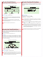
●Trim and Sub Trim Operation
The sub trim is a convenient feature but it could also complicate the setting process if used incorrectly. Use the sub trim in the correct
manner while also referring to the sub trim operation instructions on p.21 and p.26.
[Purpose of the Trim]
When a servo is to be mounted onto a model, it is usually connected to the
receiver temporarily to enable the transmitter to check its neutral position
before it is installed. However, upon running the model it is often the case
that it does not run in a straight line and the steering servo's neutral position
has to be readjusted. This adjustment function is known as the “trim,” but trim
adjustment is not only done at the beginning, but it also must be done during
model operation to account for factors such as tire wear and chassis warp.
However, using the normal trim to make these intermediary adjustments could
cause other problems. In the case of the steering trim, it could lead to different
turning radii for the left and right wheels. For throttle trims on glow engine cars,
the point of maximum braking, the full open position of the carburetor, etc.
would be shifted. For this reason, the normal trims are designated as “center
trims” that only adjust the neutral position, while a new function called sub trim
is used in conjunction to enable the most optimal settings.
●Trim (Center Trim)
Adjusting neutral position only.
Left/Right movement range
is fixed.
P
Initially, steering trim and throttle trim are
assigned to ET1 and ET2 respectively.
[Purpose of the Sub Trim]
The effect of the sub trim is illustrated in the image on the right. Adjusting
the sub trim also moves the left/right angle range. In contrast, the center
trim moves the neutral position without changing the angle range position.
However, trying to compensate the neutral position while making large sub
trim adjustments may throw off the model's left/right balance.
●Sub Trim
Left/Right angle range and neutral position can b
both be adjusted.
[Actual Setting Sequence]
When installing R/C equipment, the servo's neutral position is set first,
then final adjustments would be made with the sub trim after installation.
However, if the sub trim setting value is high, adjust the neutral position
again.
Test run to confirm neutral position. Adjustments during this time should also
be made with the sub trim. After neutral position is fixed, adjust steering
balance (p.21) so that the left and right wheels have the same turning
radius and use steering travel (p.20) to adjust overall steering angle.
During the course of practice or racing, use the center trim to correct slight
changes to the neutral position. If the setting value becomes high, correct
in conjunction with the sub trim so that the center trim value is zero.
P
Use the sub trim to adjust settings prior to driving instead of the center trim.
P
Install R/C equipment when the sub trim setting value becomes low.
P
If the neutral position becomes slightly off during driving, use center trim to correct.
14
P
The sub trim is accessed via the function menu,
but the steering trim can be assigned to one of
the ET keys in SETUP.
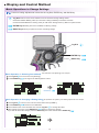
■ Display and Control Method
●Basic Operations to Change Settings
Control of setting adjustments is done via the Jog Dial, ENTER key, and BACK key.
Jog Dial:Used to move cursor between menu choices and change setting values.
Clockwise Rotation:Raising value (for L/R cases: raising toward R); Proceed to next item
Counterclockwise Rotation:Lowering value (for L/R cases: raising toward L); Return to previous item
ENTER Key:Selecting item to be modified; Confirming change
BACK Key:Returning to previous screen; Canceling change
Jog Dial
ENTER Key
BACK Key
Basic Operation 1: Selecting from a Menu
This explanation uses [Steering] as an example.
Use Jog Dial to move cursor over [Steering].
Press ENTER key
to change to the Steering Menu screen.
ENTER Key
Basic Operation 2: Changing a Setting Value
This explanation uses [TURN 1] on the Steering Speed screen as an example.
Use Jog Dial
to move cursor over the 100% value next to [TURN 1].
Press ENTER key
to select it for modification.
Once selected, the cursor will blink. Now use the Jog Dial
to change the value.
After changing the value, press ENTER key
again to confirm the change.
If you wish to cancel the change, press the BACK key at this time instead of the ENTER key
15
.
●Startup Screen and Initial Screen
When the transmitter is switched on, the startup screen will display, followed by the initial screen.
Pressing the ENTER key during the startup screen will allow you to proceed to the initial screen.
Startup Screen
Version Information:
Displays the version of the program that is installed in the Master Unit's
CPU.
This product's performance may be upgraded via paid or free upgrades. Check the KO
Propo website for information regarding such upgrades. (http://www.kopropo.co.jp)
Initial Screen
Model Number:Displays the currently selected model number.(p.18)
Model Name:Displays the name of the currently selected model number.(p.18)
Steering Trim Monitor:Displays the position of the steering trim.(p.20)
Throttle Trim Monitor:Displays the position of the throttle trim.(p.25)
Function Monitor:Functions that are in active will be lit up.
IUP:Idle Up
ACC:Throttle Acceleration
BOR:Brake Override
DBK:Drag Brake
AUT:Throttle Auto Start
ABS:Throttle ABS
SOR:Steering Travel Override
TIM:Timer Activated (including Throttle Start Ready)
Power Source Type:Displays the type of battery being used.(p.53)
DR:R03/AAA/UM4 Alkaline Batteries
NI:Ni-MH
LP:Li-Po
LF:Li-Fe
Notice) If you switch battery types, make sure to also change the [Battery Management] setting.
Voltage:Displays the current power source voltage.
Operation Time:Displays how long the transmitter has been used. (p.52)
2.4G Band:Displays the 2.4G Band Mode. (p.52)
G:GENERAL
F:FRANCE
Response Mode:Displays the Steering (S) and Throttle (T) Response (p.50)
ADV:Advanced High Speed
HSPD:Super High Speed
NORM:Normal Speed
Control Mode:Displays 3CH (3) and 4CH (4) control mode. (p.34)
On the 4CH response output will be displayed.
--:OFF
2WAY:
3WAY:
5WAY:
2WAY
3WAY
5WAY
ANLG:
ANALOG
4WS:4WS Mixing
AMP:Amp Mixing
TH-M:
Throttle Mixing
Direct Button:Displays the functions assigned to each of the 4 buttons.(p.51)
Press the ENTER key
to proceed to [Main Menu].
16
■Function Reference
[Legend]
:Operating Procedure
(see p.15 for basic operation)
P
:Point
:Notice
●Main Menu
This an index which displays the 8 different function menus. To
switch between function menus, use the direct keys or do so via
the main menu. (If you wish to use the direct keys, they must
first be assigned.)
Model Menu (Model)
Model Menu(Model)
Save various settings as model memories Up to 40 model
memories can be named and stored.
[Functions]
(p.17)
Model Select
Operations such as selecting or copying a model.
Switch between different model memories.
Steering Menu (Steering)
Names the model memories.
Model Name
(p.20)
Model Copy
Modify settings related to steering.
Copies model memories.
Throttle Menu (Throttle)
Model Reset
(p.25)
Resets model memories.
Modify settings related to the throttle.
3CH/4CH Menu (3/4ch)
(p.34)
Modify settings related to 3CH and 4CH
Quick Setup Menu (QuickSetup)
(p.45)
Modify settings required for initial setup.
Timer Menu (Timer)
(p.46)
Operating timer-related functions.
Function Menu (Function)(p.48)
Modify settings such as the monitor and buzzer.
System Menu (System)
(p.50)
Modify system-related functions such as key assignment
and pairing.
17
Model Select(MDL-Select)
Model Name(MDL-Name)
Switch between different model memories.
Example
If you have multiple cars, it is convenient to have a separate
model memory for each one. Even in the case of only one car,
you could save specific settings for different courses as different
model memories as well.
This function is used to name the model memory that is
currently in use. Distinguish each model memory with different
names, which may also be edited. The set model name will be
displayed on the initial screen and model select screen.
Choose one character at a time from the right side.
(Basic Operation p.15)
Select the model to be used.(Basic Operation p.15)
Setting Range Maximum 16 characters.
Setting Range MODEL:01 - 40
P
All of the various settings are registered under a model memory.
P
The settings which will be switched by Model Select are...
1)Steering Setting
2)Throttle Setting
3)3CH Setting
4)4CH Setting
5)Steering and Throttle Response
6)Setup Functions (ET1-ET5, BT1 function assignments)
7)LED Color
8)Model Name
9)Stopwatch Settings
10)Countdown Timer Settings
[Selectable Characters]
Switching model memory while driving may cause setting
mismatches and lead to an uncontrollable model. Please place the
car on a stand or switch if off before switching model memories.
P
18
To delete a character, overwrite the character to be deleted by
using the blank space at the end of each page of characters.
Model Copy(MDL-Copy)
Model Reset(MDL-Reset)
Copies the current model memory to a different model memory.
Return the current model memory to default setting values.
Example
When changing settings on the same car to match driving
conditions, it is convenient to copy the original memory before
modifying it. This function also allows you to try out new settings
while keeping your original one.
Select [YES] (hold ENTER key) to reset. Select [NO] to cancel
and return to the menu. (Basic Operation p.15)
Select the model memory to copy to, then hold the ENTER key
to copy.(Basic Operation p.15)
Setting Range MODEL:01 - 40
P
When selecting the model memory to copy to, that model
memory's name will be displayed.
P
The settings which will be switched by Model Select are...
1)Steering Setting
2)Throttle Setting
3)3CH Setting
4)4CH Setting
5)Steering and Throttle Response
6)Setup Functions (ET1-ET5, BT1 function assignments)
7)LED Color
8)Model Name
9)Stopwatch Settings
10)Countdown Timer Settings
P
After reset is finished, [COMPLETE] will flash on the screen before
returning to the menu.
P
The settings which will be switched by Model Select are...
1)Steering Setting
2)Throttle Setting
3)3CH Setting
4)4CH Setting
5)Steering and Throttle Response
6)Setup Functions (ET1-ET5, BT1 function assignments)
7)LED Color
8)Model Name
9)Stopwatch Settings
10)Countdown Timer Settings
Deleted data cannot be recovered. Be careful to avoid undesired
resets.
The contents of the model memory that is being copied to will be
overwritten. Overwritten data cannot be recovered, so be careful
to avoid undesired memory overwrites.
19
Steering Menu(Steering)
Steering Trim(ST-Trim)
Settings related to steering control.
Adjusts the neutral/center position of the steering angle range.
Also refer to Trim and Sub Trim Operation.(p.14)
[Functions]
Steering Trim
Modify the neutral position of the steering angle.
(N:Neutral L:Left R:Right)
Steering Travel
Modify the overall amount of steering movement.
Steering Balance
Modify the left/right steering angles.
Steering Sub Trim
Modify the overall steering angle range.
Steering Trim Rate
Modify the amount of movement which corresponds to one
click of the Trim button.
Trim Position
Travel Position
Steering Turn Speed
Setting Range L50 - 0 - R50(Default:0)
Modify the speed of the steering's turn movement.
Steering Return Speed
Modify the speed of the steering's return movement.
Steering Punch
Modify how much the steering initially turns from neutral
position.
P
Setting adjustments prior to driving should be carried out with the
sub trim, not the trim.
P
The setting range cannot exceed what is set by [Steering Travel] or
[Steering Balance].
Steering Curve
Modify the movement speed ratio which corresponds to
steering angle.
Steering Reverse
Modify the steering direction.
Travel Override
Setting or switching the steering angle.
Steering Travel(ST-Travel)
Adjust the overall amount of steering servo movement when the
steering wheel is at full lock.
(N:Neutral L:Left R:Right)
Balance Position
Travel Position
Setting Range 0 - 150(Default:100)
P
Since the Balance setting value is a ratio of the Travel setting
value, if the latter is modified the actual movement value and
the displayed graphic will also change.(the Travel value will not
change).
Steering will not operate if the Travel value is set to 0.
20
Steering Balance(ST-Balance)
Steering Sub Trim(ST-SubTrim)
Adjust the left/right steering angles independently. This enables
the turning radii to match up during cornering.
Adjust the position of the overall steering angle range. Use this
to match the neutral position when installing the steering servo.
Also refer to Trim and Sub Trim Operation.(p.14)
(N:Neutral L:Left R:Right)
Example
The servo horn position can be adjusted by the linkages, etc.
when the servo is installed onto the model, but in case this does
not set the neutral position, this function can be used to set it
from the transmitter.
(N:Neutral L:Left R:Right)
Balance L Position
Travel Position
Balance R Position
Setting Range (Default:70%)
L:30 - 100%
R:30 - 100%
P
The set percentage is a ratio of the value set by the Steering
Travel.
P
Steering balance can be adjusted by using the steering wheel
and ET key!
If an ET key that is assigned to steering trim is pressed while the
steering is turned over halfway in either direction, the balance of
the direction of the turn can be adjusted.
However, this cannot be done while on the Function Menu or
System Menu screens.
P
Sub Trim Position
Steering Angle Image
(Dotted Line:Neutral Position)
Setting Range L80 - 0 - R80(Default:0)
P
If the sub trim value becomes large, adjust the servo horn position
or linkages so that the value becomes closer to 0. If the sub trim
value is too large, dead zones could result and the servo may not
operate at the extremities of its movement range.
Steering Trim Rate(TrimRate)
If the trim is set to a large value, a large left/right value discrepancy
may result. If adjusting steering balance for the first time, follow the
procedures below.
Adjusts the amount of movement associated with one click of
the trim button. This setting screen is common with the throttle.
Set trim value to 0.
Adjust sub trim so that the car drives in a straight line when
steering is in neutral position.
Use steering travel to match the overall steering angle range.
Use steering balance to match the left/right turning radii.
If the car does not drive straight at this point, use trim to correct.
Setting Range
STEERING:1 - 10 intervals (Default:5)
THROTTLE:see Throttle Trim Rate
21
P
Although the amount of movement of one interval can be adjusted,
the lower the number the smaller the amount of movement.
P
The overall number of intervals does not change, so a change in
trim rate will result in a change in the range in which the trim can
be used to make corrections.
P
If the trim rate is changed when the trim is already set, the trim
may be thrown off. If the trim setting is 0 then this does not
apply.)
P
Lower trim rates enable fine adjustments, but the effects may not be
apparent depending on the servo used. If there is a lot of slop in the
linkage or servo saver, fine trim adjustments could cause the user to
constantly worry about the trim settings. In that case, please reexamine
the linkages, etc.
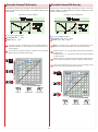
Steering Turn Speed(TurnSpeed)
Steering Return Speed(RetnSpeed)
This function limits the maximum speed of the steering servo
by adjusting the steering turn direction [TURN] setting. The
steering angle between neutral and full lock is split into two
zones and each may be adjusted independently (2WAY).
This function limits the maximum speed of the steering servo
by adjusting the steering return direction [RETURN] setting.
The steering angle between neutral and full lock is split into two
zones and each could be adjusted independently (2WAY).
(N:Neutral)
(N:Neutral)
Setting Range
RETNPOS:1 - 100%(Default:50%)
Setting Range
TURNPOS:1 - 100%(Default:50%)
This sets the point at which the two speed zones are split.
This sets the point at which the two speed zones are split.
TURN 1:1 - 100%(Default:100%)
RETN 2:1 - 100%(Default:100%)
This sets the speed from when the steering has begun to turn.
This sets the speed before the split position point.
TURN 2:1 - 100%(Default:100%)
RETN 1:1 - 100%(Default:100%)
This sets the speed from after the split to the second zone.
This sets the speed from after the split to the second zone.
If your car flips on high-grip surfaces, lower the [TURN 1] value to
make cornering easier.
P
[Changing to 1WAY]
Changing [TURNPOS] to 100 will deactivate [TURN 2] and [TURN
1] will be used to set the speed.
P
Effective speed values are dependent on the speed characteristics
of your selected servo.
OS
)
Take into account such factors as the servo used, car, driving
surface, etc. when adjusting all settings. Conduct test drives to find
the best setting values.
P
Effective speed values are dependent on the speed characteristics
of your selected servo.
Wheel Operation
ee
ck
o
lL
l
Fu
Neutral
Zo
ne
(P
Elapsed Time
Sp
2
n
P
Full Lock
d
sit
ion
Po
Tu
r
Turn 1
Speed
Zone
Take into account such factors as the servo used, car, driving
surface, etc. when adjusting all settings. Conduct test drives to find
the best setting values.
Neutral
P
[Changing to 1WAY]
Changing [RETNPOS] to 100 will deactivate [RETN 2] and [RETN 1]
will be used to set the speed.
Begin Turn
Neutral
Quick Operations
Return
Elapsed Time
Full Lock
Speed Position
Servo Movement
Neutral
Servo Speed
Different values will affect the graph's appearance
22
R
Po
sit
etu
ion
rn
(P
2
OS
Sp
)
ee
d
Zo
ne
P
P
1 Spe
ed Zo
ne
You can set the speed to be slow during initial turning, then
subsequently faster.
Return
P
k
oc
lL
l
Fu
Steering Curve(ST-Curve)
Steering Punch(ST-Punch)
This function adjusts the ratio of the steering angle to servo
movement speed (Curve Characteristics). Choose between (+)
Quick Curve and (-) Mild Curve.
This function quickens the steering's initial response and can
be used to instill a strong turning movement when the steering
initially moves from neutral.
(N:Neutral L:Left R:Right)
(N:Neutral L:Left R:Right)
Setting Range OFF, 1 - 50%(Default:OFF)
The larger the value, the stronger the amount of turning
movement.
P
This could be effective if steering linkages have a lot of slop, but
please note that it does not improve straight-line performance.
P
When using this in conjunction with other functions such as
[Steering Speed], adjust one at a time to confirm their effects to
produce an effective overall setting.
P
As the graph shows, servo movement speed can be changed
according to wheel movement angle.
Positive values (+1 to +100) equal high initial response followed by
mild response.
Negative values (-1 to -100) equal a mild initial response followed
by high response.
P
When using this in conjunction with other functions such as
[Steering Speed], adjust one at a time to confirm their effects to
produce an effective overall setting.
P
To adjust only the steering's initial response, use the [Steering
Punch] function.
0
A
+
0
0
t
0
−
1
0
0
A
t
t
t
1
A
Servo Movement Angle
+5
0
At
A
Servo Movement Angle
P
Setting Range -100 - OFF - 100%(Default:OFF)
Wheel Movement
Wheel Movement
23
Steering Reverse(ST-Reverse)
Travel Override(Travel Override)
This function reverses the steering direction. This setting screen
is common with the throttle.
Adjust the steering angle according to the driving conditions to
make the car easier to control.
Example
Use this function when, after installing the servo, movements
are the opposite of transmitter inputs (turning the steering wheel
right results in wheels turning left, etc.).
Example
Convenient for changing the steering angle on straights to give
the car better straight-line stability.
Setting Range
KEY:OFF, ET1 - 5, BT1(Default:OFF)
Setting Range (Default:NOR)
STEERING:REV(Reverse), NOR(Normal)
THROTTLE:see [Throttle Reverse]
Assigns a key to be used to switch between the steering
travel/balance settings and the travel override.
TRAVEL:0 - 150(Default:100)
Sets the travel override's travel setting.
Steering direction varies from car to car and should be checked
when the R/C equipment has been installed.
BALANCE L:40 - 100%(Default:70%)
BALANCE R:40 - 100%(Default:70%)
Sets the balance of the travel override. R and L refer to the
balance when turning right and left respectively.
For detailed explanations of travel and balance, refer to
[Steering Travel]and [Steering Balance]
24
P
[SOR] Display on the Function Monitor!
Operating the key that is assigned by [KEY] will result in [SOR]
being displayed on the initial screen's function monitor. If that key
is pressed while at the initial screen, [SOR] will disappear from the
function monitor.
P
The setting value percentage is a ratio of the travel value set during
[Steering Travel].
P
Steering balance can be adjusted by using the steering wheel
and ET key!
When travel override is ON, if an ET key that is assigned to
steering trim is pressed while the steering is turned over halfway
in either direction the balance of the direction of the turn can be
adjusted.
However, this cannot be done while on the Function Menu or
System Menu screens.
Throttle Menu(Throttle)
Throttle Trim(TH-Trim)
Settings related to throttle control.
Adjusts the neutral/center position of the throttle range.
Also refer to Trim and Sub Trim Operation. (p.14)
[Functions]
Throttle Trim
(N:Neutral F:Forward B:Brake)
Modify the neutral position of the throttle.
Throttle High Point
Modify the maximum amount of throttle movement (towards
forward acceleration).
Throttle Brake
Modify the maximum amount of throttle brake movement.
Throttle Sub Trim
Modify the overall throttle movement range.
Throttle Trim Rate
Trim Position
Brake Position
Modify the amount of movement which corresponds to one
click of the throttle trim button.
Throttle Turn Speed
High Point Position
Setting Range F50 - 0 - B50(Default:0)
Modify the speed of the throttle's movement (towards
forward acceleration).
Throttle Return Speed
Modify the speed of the throttle's return movement.
Throttle Punch
Modify how much the throttle initially accelerates from
neutral position.
P
Setting adjustments prior to driving should be carried out with the
sub trim, not the trim.
P
The setting range cannot exceed what is set by [Throttle High
Point] or [Throttle Brake].
Throttle Curve
Modify the movement speed ratio which corresponds to how
much throttle is applied.
Throttle Reverse
Throttle High Point(TH-Point)
Modify the throttle direction.
Throttle Drag Brake
Adjust the maximum amount of throttle forward acceleration
movement.
Modify the amount of neutral braking.
Brake Override
Example
This makes it particularly easy to adjust a glow engine car's
high carburetor setting. For electric cars, this is used to set the
point of the ESC's highest speed.
Modify of switch the maximum amount of braking.
Throttle ABS
Modify the amount of brake pumping.
Throttle Acceleration
(N:Neutral F:Forward B:Brake)
Modify the amount of acceleration burst of the throttle.
Throttle Auto-Start
Set the amount of throttle automatically at startup.
Idle Up
Modify the neutral position of the throttle trigger.
High Point Position
Brake Position
Setting Range 0 - 150(Default:100)
P
On glow engine cars, an overly high setting value will increase load
on the servo and lead to it being damaged. Check carefully while
adjusting.
P
On electric cars, a setting value that is too small may cause
problems with the ESC settings. Make adjustments starting from
the default setting (100).
P
If the throttle high point is set low and the trim is set to a high
value toward acceleration, the resulting throttle movement may be
extraordinarily small.
Throttle will not operate if the High Point value is set to 0.
25
Throttle Trim Rate(TH-TrimRate)
Throttle Brake(TH-Brake)
Adjusts the amount of movement associated with one click of
the throttle trim button. This setting screen is common with the
steering.
Adjust the maximum amount of brake movement.
(N:Neutral F:Forward B:Brake)
High Point
Brake Position
Setting Range
STEERING:see [Steering Trim Rate]
THROTTLE:1 - 10 intervals (Default:5)
Setting Range 0 - 150(Default:100)
P
On glow engine cars, an overly high setting value will increase
load on the servo and lead to it being damaged. Check carefully
while adjusting.
P
On electric cars, a setting value that is too small may cause
problems with the ESC settings. Make adjustments starting from
the default setting (100).
P
The overall number of intervals does not change, so a change in
trim rate will result in a change in the range in which the trim can
be used to make corrections.
P
If the trim rate is changed when the trim is already set, the trim
may be thrown off. If the trim setting is 0 then this does not
apply.)
P
Lower trim rates enable fine adjustments, but the effects may not
be apparent depending on the servo used. If there is a lot of slop
in the linkage or servo saver, fine trim adjustments could cause
the user to constantly worry about the trim settings. In that case,
please reexamine the linkages, etc.
P
Although the amount of movement of one interval can be adjusted,
the lower the number the smaller the amount of movement.
Brake will not operate if the value is set to 0.
Throttle Sub Trim(TH-SubTrim)
Adjust the position of the overall throttle movement range. Use
this function when the neutral position cannot be centered with
only linkage adjustment.
Also refer to Trim and Sub Trim Operation. (p.14)
Example
The servo horn horn position can be adjusted by the linkages,
etc. when the servo is installed onto the model, but in case the
neutral position cannot be centered, this function can be used to
set it from the transmitter.
(N:Neutral F:Forward B:Brake)
Sub Trim Position
Steering Angle Image
(Dotted Line:Neutral Position)
Setting Range F80 - 0 - B80 (Default:0)
P
If the sub trim value becomes large, adjust the servo horn position
or linkages so that the value becomes closer to 0. If the sub trim
value is too large, dead zones could result and the servo may not
operate at the extremities of its movement range.
26
P
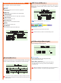
Throttle Turn Speed(TH-TurnSpeed)
This function delays the conversion of the throttle control signal
to make the car easier to control. The speed of the forward
acceleration direction [TURN] is split into three zones and each
may be adjusted independently (3WAY).
Turn Speed may be set to be divided into two zones (2WAY) or
have no divisions at all (1WAY).
[Changing to 2WAY]
Changing the two [TURNPOS] to the same value will deactivate
[TURN M]. [TURN H] and [TURN L] will be used to set the speed.
The [RETURN] direction is adjusted with [Throttle Return Speed].
Example
If the car spins or otherwise does not drive straight when the
throttle is applied suddenly, limiting the throttle speed can be
effective.
(N:Neutral F:Full Acceleration L:Low Speed Zone
M:Mid Speed Zone H:High Speed Zone)
[Changing to 1WAY]
Changing the two [TURNPOS] to 100 will deactivate [TURN M] and
[TURN H]. [TURN L] will be used to set the speed.
Setting Range
TURNPOS L>M:1 - 100%(Default:30%)
This sets the point between the low and mid-speed
acceleration zones.
P
TURNPOS M>H:1 - 100%(Default:80%)
This sets the point between the mid and high speed
acceleration zones.
This is effective for both glow engine cars as well as electric cars
with ESCs.
Throttle Turn Speed only affects the throttle's forward acceleration.
It does not affect the brake.
TURN L:1 - 100%(Default:100%)
This sets the speed during the low speed acceleration zone.
TURN M:1 - 100%(Default:100%)
This sets the speed during the mid speed acceleration zone.
TURN H:1 - 100%(Default:100%)
This sets the speed during the high speed acceleration zone.
P
This product enables you to set throttle speed to either POSITION
or SPEED. (Depending on the POSITION setting, SPEED's
modifiable settings may change.)
P
[TURNPOS L > M] is always the smaller or equal value to
[TURNPOS M > H]. Even if you try to set it otherwise, the values
will automatically correct themselves.
Neutral
Speed L Limited Zone
Position
Speed H Limited Zone
Full Acceleration
Neutral
TURNPOS L>M
TURNPOS M>H
Full Acceleration
27
P
Throttle Return Speed(TH-ReturnSpeed)
This function delays the conversion of the throttle control signal
to make the car easier to control. The speed of the deceleration
direction [RETURN] is split into three zones and each may be
adjusted independently (3WAY).
Return Speed may be set to be divided into two zones (2WAY) or
have no divisions at all (1WAY).
[Changing to 2WAY]
Changing the two [RETNPOS] to the same value will deactivate
[RETN M]. [RETN H] and [RETN L] will be used to set the speed.
The [TURN] direction is adjusted with [Throttle Turn Speed].
Example
If the car spins or locks up the brakes when the throttle is
released suddenly, limiting the throttle speed can be effective.
(N:Neutral F:Full Acceleration L:Low Speed Zone
M:Mid Speed Zone H:High Speed Zone)
[Changing to 1WAY]
Changing the two [RETNPOS] to 100 will deactivate [RETN M] and
[RETN H]. [RETN L] will be used to set the speed.
Setting Range
RETNPOS H>M:1 - 100%(Default:80%)
This sets the point between the low and mid-speed
deceleration zones.
RETNPOS M>L:1 - 100%(Default:30%)
This sets the point between the mid and high speed
deceleration zones.
P
This is effective for both glow engine cars as well as electric cars
with ESCs.
RETN L:1 - 100%(Default:100%)
This sets the speed during the low speed deceleration zone.
RETN M:1 - 100%(Default:100%)
This sets the speed during the mid speed deceleration zone.
RETN H:1 - 100%(Default:100%)
This sets the speed during the high speed deceleration zone.
Neutral
P
P
Neutral
Speed L Limited Zone
Speed L Limited Zone
This product enables you to set throttle speed to either POSITION
Position
or SPEED. (Depending on the POSITION setting, SPEED's
Speed H Limited Zone
modifiable settings may change.)
Full Acceleration
[RETNPOS L > M] is always the smaller or equal value to
[RETNPOS M > H]. Even if you try to set it otherwise, the values
will automatically correct themselves.
Position
Speed H Limited Zone
Full Acceleration
Neutral
Neutral
TURNPOS L>M
TURNPOS M>L
TURNPOS M>H
TURNPOS H>M
Full Acceleration
Full Acceleration
28
Throttle Curve(TH-Curve)
Throttle Punch(TH-Punch)
This function quickens the throttle's initial response and can be
used to instill a sense of power when the throttle initially moves
from neutral.
This function sets the signal conversion rate to a curve to
enable quicker or milder response. Likewise, braking can also
be set to a braking curve.
(N:Neutral F:Forward B:Brake)
(N:Neutral F:Forward B:Brake)
Setting Range (Default:OFF)
Setting Range (Default:OFF)
FORWARD:OFF, 1 - 50%
BRAKE:OFF, 1 - 50%
FORWARD:-100 - OFF - 100%
BRAKE:-100 - OFF - 100%
The larger the value, the larger the amount of throttle movement.
However, depending on other settings, the throttle operation may
become jagged.
P
When [Throttle Punch] is activated, the characteristics of the
throttle curve value is also added to the Throttle Punch value.
If using this in conjunction with other functions such as [Throttle
ABS], confirm the operation before using.
P
Positive values (+1 to +100) equal high initial response followed by
mild response.
Negative values (-1 to -100) equal a mild initial response followed
by high response.
P
When using this in conjunction with other functions, adjust one at a
time to confirm their effects to produce an effective overall setting.
P
This function adjusts only the curve. Use the [Throttle Punch]
function if you wish to adjust the initial response.
50
At
0
Neutral
Half Throttle
Full Throttle
A
t
+
1
0
0
t
0
0
0
A
−
1
Wheel Movement
Quick
t
t
Servo Movement Angle
A
A
Servo Movement Angle
At 80
Mild
Wheel Movement
Neutral
29
Half Throttle
Full Throttle
Brake Override(Brake Override)
Throttle Reverse(TH-Reverce)
This function reverses the throttle direction. This setting screen
is common with the steering.
Arrange another maximum brake setting, which can be
activated/deactivated by the ET lever or BT button.
Example
Use this function when, after installing the servo, movements are
the opposite of transmitter inputs (pulling the trigger to accelerate
forward results in reverse movement).
Example
If a change in driving conditions is foreseen, the throttle brake
setting can be changed during driving.
Setting Range
KEY:OFF, ET1 - 5, BT1(Default:OFF)
Setting Range (Default:NOR)
STEERING:see [Steering Reverse]
THROTTLE:REV(Reverse), NOR(Normal)
P
Assigns a key to be used to activate/deactivate the brake
override.
If brake override is deactivated, the throttle brake setting
will be activated.
For electric cars, the throttle is set by the ESC so there is no need
to set this function. However, some older ESCs will not function
properly unless reverse is also set.
BRAKE:0 - 100%(Default:100%)
Sets the brake override's brake setting.
For detailed explanations of the brake function, refer to
[Throttle Brake].
Throttle Drag Brake(TH-DragBrake)
This function enables a light brake application at the moment
when the throttle position changes from acceleration to
deceleration.
P
Like Travel Override, this function is used to change the brake
setting. If a change in driving conditions is foreseen, the throttle
brake setting can be changed during driving.
Example
Normally, the throttle would return to neutral when it is released
from acceleration. However, depending on the type of vehicle
or race, a light application of brake at this moment may make
driving easier.
P
[BOR] Display on the Function Monitor!
If the key assigned to brake override is pressed, [BOR] will be
displayed on the initial screen's function monitor. If this key is
pressed while at the initial screen, [BOR] will disappear from the
function monitor.
Setting Range (Default:OFF)
KEY:OFF, ET1 - 5, BT1
Assigns a key to be used to activate/deactivate the drag brake.
BRAKE:OFF, 0.5 - 50.0 {increments of 0.5}
Sets the amount of neutral brake.
P
If [BRAKE] is set to any value other than OFF, drag brake will be
activated. Drag brake can also be activated/deactivated via the
key assigned by [KEY].
P
[DBK] Display on the Function Monitor!
If [BRAKE] is not set to OFF, [DBK] will be displayed on the initial
screen's function monitor. If the key assigned to drag brake is
pressed while at the initial screen, [DBK] will disappear from the
function monitor.
30
Throttle ABS(TH-ABS)
[Regarding WIDTH and TRG.P]
To prevent tires from locking up during sudden braking, brake
pumping will be applied.
P
P
The amount of ABS applied by the servo is determined by the
amount of throttle trigger movement as well as the [WIDTH] and
[TRG.P] setting values. Using the throttle trigger position as a base
and with [WDITH] set at 100, the servo will return to the point set
by [TRG.P]. If the [WIDTH] value is too small, the servo will not be
able to return to the point set by [TRG.P].
P
The smaller the [TRG.P] value, the more brake pumping the servo
will apply.
Example
This function is effective when your car's wheels lock up under
braking and disturbs the car's balance. It will help enable
smooth cornering performance.
(n:Neutral B.MAX:Maximum Brake)
Setting [WIDTH] to 0 will deactivate ABS.
[Regarding CYCLE]
P
If [CYCLE] is set at a large value, the servo's operation frequency
will increase.
P
Setting a high value will increase the servo's power consumption and
may also simultaneously shorten the lifespan of the servo.
[Regarding DELAY]
P
Setting Range
WIDTH:OFF, 1 - 100%(Default:OFF)
During the time that is set by this function, the brakes will be
applied strongly rather than the ABS.
[Regarding DUTY]
Sets the amount of brake pumping.
P
TRG.P:5 - 100%(Default:60%)
Sets the function's starting position.
CYCLE:1 - 30(Default:28)
Sets the speed of the brake pumping.
[DUTY] is used to set the ABS brake application to release ratio to
one of 9 steps.
DUTY Ratio = (A) Time that brake is applied :
(B) Time that brake is released
[Regarding KEY]
DELAY:OFF, 1 - 100(Default:OFF)
Sets the delay time before the function's operation.
P
Activate ABS While Driving!
If [WIDTH] is not set to OFF, pressing the assigned key during
driving will activate/deactivate ABS.
P
For electric cars, it may be easier to understand if the throttle
channel is connected temporarily to the servo to check ABS
operation instead of to the ESC.
P
Actual ABS effectiveness may differ according to the servo used.
Optimum settings will differ due to different torque and speed
values.
P
[ABS] Display on the Function Monitor!
If [WIDTH] is not set to OFF, [ABS] will be displayed on the initial
screen's function monitor. If the key assigned to ABS is pressed
while at the initial screen, [ABS] will disappear from the function
monitor.
DUTY:10 - 90%(Default:50%)
Sets the duration of the brake pumping.
KEY:OFF, ET1 - 5, BT1(Default:OFF)
Assigns a key to be used to activate/deactivate the ABS.
Elapsed Time
Full Brake
Throttle Operation
Throttle moved
toward braking.
Neutral
Elapsed Time
Full Brake
WIDTH(50)
Servo Movement
Neutral
TRG.P(30)
DUTY
CYCLE
31
Throttle Acceleration(TH-Accel)
[Regarding WIDTH]
Just like professional drivers who are capable of precise throttle
inputs, this function enables fine throttle adjustments to allow
quicker cornering.
Example
By setting the throttle to feather automatically, the car could be
made to grip and corner faster on low-grip surfaces.
(n:Neutral F.MAX:Full Throttle)
P
Setting [WIDTH] to 0 will deactivate ABS.
[Regarding TRG.L and TRG.H]
P
Throttle feathering will occur when the throttle trigger is moved to
the positions set by [TRG.L] and [TRG.H].
P
The function settings have the following relationship: [TRG.L ≤
TRG.H]. Thus the [TRG.L] value will always correct itself to be less
than the [TRG.H] value.
[Regarding CYCLE]
P
If [CYCLE] is set at a large value, the servo's operation frequency
will increase.
P
Setting a high value will increase the servo's power consumption and
may also simultaneously shorten the lifespan of the servo.
[Regarding KEY]
P
Activate ACC While Driving!
If [WIDTH] is not set to OFF, pressing the assigned key during
driving will activate/deactivate ACC.
P
[ACC] Display on the Function Monitor!
If [WIDTH] is not set to OFF, [ACC] will be displayed on the initial
screen's function monitor. If the key assigned to ACC is pressed
while at the initial screen, [ACC] will disappear from the function
monitor.
Setting Range
WIDTH:OFF, 1 - 100%(Default:OFF)
Sets the amount of throttle feathering.
TRG.L:1 - 100%(Default:5%)
Sets the function's starting position.
TRG.H:1 - 100%(Default:50%)
Sets the function's completion position.
Take into account such factors as the servo used, car, driving
surface, etc. when adjusting all settings. Conduct test drives to
find the best setting values.
CYCLE:1 - 30(Default:28)
Sets the speed of the throttle feathering.
KEY:OFF, ET1 - 5, BT1(Default:OFF)
Setting a large [CYCLE] or [WIDTH] value may increase the
servo's power consumption and also shorten its lifespan.
Assigns a key to be used to activate/deactivate the Acceleration
Function.
Elapsed Time
Full Throttle
Throttle Operation
Throttle moved
toward acceleration.
Neutral
Elapsed Time
High
Servo Movement
TRG.H
WIDTH
TRG.L
Neutral
CYCLE
32
Throttle Auto-Start(TH-AutoStart)
Idle Up(IdleUp)
This function sets the throttle output to a fixed level at startup,
regardless of how much the throttle trigger is pulled.
Example Launching from the starting line.
Used to offset the throttle's neutral position.
Example
Raising the idling has the effect of improving a glow engine
car's launch performance. It is also useful for canceling the
neutral brake of a motor with strong cogging and preventing
engine stalls when glow engine cars enter the pit for refueling.
Setting Range
KEY:OFF, ET1 - 5, BT1(Default:OFF)
Assigns a key to be used to activate/deactivate the
Auto-Start Function.
Setting Range
KEY:OFF, ET1 - 5, BT1(Default:OFF)
TRG.P:5 - 100%(Default:5%)
Assigns a key to be used to activate/deactivate the Idle Up
Function.
Sets the trigger position at which the function operates.
FORWARD:OFF - 100%(Default:OFF)
BUTTON:TGLE, PUSH(Default:TGLE)
Sets the function's throttle position.
Sets the method of activation.
P
The function will not operate until the throttle trigger reaches the set
position.
P
When the throttle is released, the function is deactivated and the
throttle returns to normal operation.
P
If the key assigned to Auto-Start is pressed, [AUT] will be displayed
on the initial screen's function monitor. If this key is pressed while at
the initial screen, [AUT] will disappear from the function monitor.
Normally, full throttle is set for launching from the starting line.
However, tire and surface conditions may mean full throttle will not
be effective. Conduct tests and make adjustments
TGLE:If a key is assigned to Idle Up, press once to
activate (2 beeps) and press again to deactivate (1 beep).
PUSH:It is only activated controls are operated and is
deactivated when controls are released.
C.TRM: -100 - 100(Default:0)
Sets the amount of throttle neutral offset.
P
Throttle can be operated even when Idle Up is activated. The high
point and brake point do not change during this time.
P
If the key assigned to Idle Up is pressed, [IUP] will be displayed on
the initial screen's function monitor. If this key is pressed while at
the initial screen, [IUP] will disappear from the function monitor.
Please note that if the transmitter is switched on while Idle Up is
activated, a malfunction could occur.
33
3CH/4CH Menu(3/4ch Menu)
Control Mode(Control Mode)
Set the usage choice for channels 3 and 4.
3Settings related to 3CH and 4CH operations.
(In order to operate 3CH and 4CH, the response function's OUTPUT
setting must be changed from 2CH to 4CH.)
[Functions]
3CH Control Menu
Adjusts settings related to 3CH.
4CH control Menu
Adjusts settings related to 4CH.
Setting Range (Default:OFF)
2WAY(Modify the 2-interval output settings.),
3WAY(Modify the 3-interval output settings.),
5WAY(Modify the 5-interval output settings.),
ANALOG(Modifies settings for continuous output.),
For example steering and throttle.
P
4WS-MIX(Modify settings related to 4-wheel steering.),
AMP-MIX(Modify settings related to 4-wheel drive.),
T-MIX(Modify independent settings for brake operation.)
The functions which may be set are the same for both 3CH and
4CH. Set them to match the desired purpose.
Control Menu(Control Menu)
Various settings related to the use of channels 3 and 4 may be
adjusted. You can select from 2WAY, 3WAY, 5WAY, ANALOG,
4WS MIX, AMP MIX, and T-MIX operations, which can be set in
control mode according to the desired purpose.
2WAY(2WAY)
[Functions]
Control Mode
Modify the 2-interval output settings.
Set the usage choice for channels 3 and 4.
(select from 2/3/5WAY, ANALOG, 4WS/AMP/TH Mixing)
Example
May be used to activate/deactivate an engine starter unit or a
semi-trailer's support legs.
2WAY
Modify the 2-interval output settings.
3WAY
Modify the 3-interval output settings.
5WAY
Modify the 5-interval output settings.
ANALOG
Modifies settings for analog (continuous) output.
(For example steering and throttle.)
4WS Mixing
Modify settings related to 4-wheel steering.
START position (white square)
Position aside from START (black square)
AMP Mixing
Modify settings related to 4-wheel drive.
Setting Range
START:POS 1, POS 2(Default:POS 1)
T-Mixing
Modify independent settings for brake operation.
Sets the starting position.
KEY:OFF, ET1 - 5, BT1(Default:OFF)
Assigns a key to use for switching positions.
POS 1:-100 - 100%(Default:-100%)
Sets Position 1's output position.
POS 2:-100 - 100%(Default:100%)
Sets Position 2's output position.
34
5WAY(5WAY)
3WAY(3WAY)
Modify the 3-interval output settings.
Modify the 5-interval output settings.
Example
May be used for gear changing operations or when you wish to
set a 3-interval control scheme for the servo.
Example
May be used for gear changing operations or when you wish to
set a 5-interval control scheme for the servo.
START position (white square)
Position aside from START (black square)
START position (white square)
Position aside from START (black square)
Setting Range
START:POS 1, POS 2, POS 3(Default:POS 1)
Setting Range
Sets the starting position.
START:POS 1, POS 2, POS 3, POS 4, POS 5
(Default:POS 1)
Sets the starting position.
KEY:OFF, ET1 - 5, BT1(Default:OFF)
Assigns a key to use for switching positions.
KEY:OFF, ET1 - 5, BT1(Default:OFF)
POS 1:-100 - 100%(Default:-100%)
Assigns a key to use for switching positions.
Sets Position 1's output position.
POS 1:-100 - 100%(Default:-100%)
POS 2:-100 - 100%(Default:0%)
Sets Position 1's output position.
Sets Position 2's output position.
POS 2:-100 - 100%(Default:-50%)
POS 3:-100 - 100%(Default:100%)
Sets Position 2's output position.
Sets Position 3's output position.
POS 3:-100 - 100%(Default:0%)
Sets Position 3's output position.
POS 4:-100 - 100%(Default:50%)
Sets Position 4's output position.
POS 5:-100 - 100%(Default:100%)
Sets Position 5's output position.
35
ANALOG(ANALOG)
These settings are to enable continuous output for channels 3
or 4.
CCEN Position (white square)
LLOW Position (black square)
HHIGH Position (black square)
Setting Range
KEY:OFF, ET1 - 5, BT1(Default:OFF)
Assigns a key to use for switching positions.
REVERSE:NOR(Normal), REV(Reverse)(Default:NOR)
Sets operation direction.
STEP:1 - 25(Default:5)
Sets the amount of change for the operation.
LOW(Low Position):-100 - 0(Default:-100)
Sets the lowest value for the operation range.
CEN(Center Position):LOW - HIGH(Default:0)
Sets the neutral position for the operation range.
HIGH(High Position):0 - 100(Default:100)
Sets the highest value for the operation range.
How to Use Analog Settings
Low Position Side:
Between LOW and CEN are 100 steps within which the intervals can be
adjusted.
High Position Side:
Between CEN and HIGH are 100 steps within which the intervals can be
adjusted.
Example)When STEP value is 2
When LOW side is set to 5 intervals.
When HIGH side is set to 4 intervals.
High Position
Maximum
High Angle
2 Steps
Center
100 Steps
Movement Range
Interval Position
2 Steps
100 Steps
Low Position
Maximum
Low Angle
P
Center position is the staring position.
P
Low/High positions cannot be exceeded. Operations which try to
do so will stop just before the Low/High positions.
36
4WS Mixing(4WSMix)
4WS Mixing Left(4WSMix LEFT)
This function is related to an R/C car's 4-wheel steering feature.
If 3CH or 4CH is assigned to control the rear axle, it will operate
in conjunction with 1CH (steering). The direction of the rear axle
steering may also be changed.
Adjusts the rear axle servo movement range when steering is
turned to the left.
Equivalent to (Balance L) in the [Steering Balance] function.
[Functions]
4WS Mixing Mode
Choose from four types of 4-wheel steering controls.
4WS Mixing Left
Modify the rear axle servo movement range when steering
is turned to the left.
4WS Mixing Center
Modify the rear axle servo's neutral position when steering
is at neutral.
Left Position (white square)
Center Position (black square)
Right Position (black square)
4WS Mixing Right
Modify the rear axle servo movement range when steering
is turned to the right.
Setting Range 0 - 100%(Default:70%)
4WS Steering Travel
Modify the movement range of the rear axle servo.
4WS Mixing Reverse
Modify the rear axle servo direction.
4WS Mixing Key
Assigns ET keys to be used for 4WS Mixing.
P
If the rear axle servo's direction has been reversed, use [4WS
Mixing Reverse] to adust.
P
This setting percentage is a ratio against the movement angle
setting in the [4WS Mixing Travel] function.
P
If the 4WS Mixing trim is set to a large value, a large left/right
value discrepancy may result. If adjusting 4WS Mixing Left for the
first time, follow the procedures below.
Set 4WS Mixing trim value to 0.
Adjust 4WS Mixing trim so that the car drives in a straight line
when steering is in neutral position.
Use 4WS Mixing Travel to match the overall steering angle
range.
Use 4WS Mixing Left and 4WS Mixing Right to match the left/
right turning radii.
4WS Mixing Center(4WSMix CENTER)
4WS Mixing Mode(4WSMix MODE)
Adjust the rear axle servo's neutral position.
Equivalent to the [Steering Sub Trim] function.
Choose from four types of 4-wheel steering controls.
Center Position (white square)
Left Position (black square)
Right Position (black square)
Setting Range (Default:NORMAL)
NORMAL(front and rear axles turn in the same direction),
REVERSE(front and rear axles turn in opposite directions),
F STEER(steer front axle only),
R STEER(steer rear axle only)
P
Setting Range -50 - 50%(Default:0%)
P
ET lever may be used for activation if is assigned to 4WS Mixing
Mode.
37
The setting range cannot exceed what is set by [4WS Mixing
Travel] or [4WS Mixing Left] and [4WS Mixing Right].
4WS Mixing Right(4WSMix RIGHT)
4WS Mixing Reverse(4WSMix REVERCE)
Adjusts the rear axle servo movement range when steering is
turned to the right.
Equivalent to (Balance R) in the [Steering Balance] function.
This function reverses the rear axle's movement direction.
Setting Range
NOR(Normal), REV(Reverse)(Default:NOR)
Right Position (white square)
Left Position (black square)
Center Position (black square)
Steering direction varies from car to car and should be checked
when the R/C equipment has been installed.
Setting Range 0 - 100%(Default:70%)
P
If the rear axle servo's direction has been reversed, use [4WS
Mixing Reverse] to adjust.
P
This setting percentage is a ratio against the movement angle
setting in the [4WS Mixing Travel] function.
P
If the 4WS Mixing trim is set to a large value, a large left/right
value discrepancy may result. If adjusting 4WS Mixing Right for
the first time, follow the procedures below.
Set 4WS Mixing trim value to 0.
Adjust 4WS Mixing trim so that the car drives in a straight line
when steering is in neutral position.
Use 4WS Mixing Travel to match the overall steering angle
range.
Use 4WS Mixing Left and 4WS Mixing Right to match the left/
right turning radii.
4WS Mixing Key(4WSMix KEY)
Assigns ET keys to be used for 4WS Mixing.
4WS Mixing Travel(4WSMix TRAVEL)
Adjusts the overall amount of movement of the rear axle servo
when the steering is at full lock.
Setting Range (Default:OFF)
MODE(4WSMix MODE):OFF, ET1 - 5
LEFT(4WSMix LEFT) :OFF, ET1 - 5
CENTER(4WSMix CENTER):OFF, ET1 - 5
RIGHT(4WSMix RIGHT):OFF, ET1 - 5
TRAVEL(4WSMix TRAVEL):OFF, ET1 - 5
Setting Range 0 - 150%(Default:100%)
Steering will not operate if the 4WS Mixing Travel value is set to 0.
38
P
ET keys may also be assigned via the [Setup] function in the
System Menu.
P
Convenient for when you need to adjust 4WS Mixing settings.
Amp Mixing Mode(AMPMix MODE)
Amp Mixing(AMP Mix)
Used when the front and rear wheels are controlled by separate
ESCs and motors.
If 3CH or 4CH is set to the front-wheel drive function, it will
operate in conjunction with 2CH's throttle operations.
Choose from five 4-wheel drive modes.
[Functions]
Amp Mixing Mode
Choose from five 4-wheel drive modes.
Amp Mixing Throttle Hold
Set either the front or rear wheels to be driven at a certain
speed.
Setting Range (Default:OFF)
NORMAL(drives both front and rear wheels),
BURN(drives rear wheels only),
DIG(drives front wheels only),
F HOLD(drives front wheels at a set speed),
R HOLD(drives rear wheels at a set speed)
For (F HOLD) and (R HOLD).
Amp Mixing High Point
Modify the maximum amount of throttle to be applied to the
front wheels.
Amp Mixing Brake
Modify the maximum amount of reverse (brake) to be applied
to the front wheels.
For (NORMAL).
P
Amp Mixing Reverse
Modify the movement direction of the front wheels.
Amp Mixing Trim
Modify the neutral position of the front wheels.
Amp Mixing ET Mode Setting
Enables 4 wheel drive [Mode] to be changed via ET lever.
Amp Mixing Key
Assigns an ET lever to be used for Amp Mixing.
39
ET lever may be used for activation if is assigned to Amp Mixing
Mode.
Amp Mixing Throttle
Hold(AMPMix HOLD)
Amp Mixing High Point
(AMPMix HIPOINT)
This function adjusts the set speed used for (F HOLD) and (R
HOLD) selected in Amp Mixing Mode.
[F HOLD] adjusts the front wheel drive while [R HOLD] adjusts
the rear wheel drive.
This setting is activated when F HOLD or R HOLD mode is
selected.
Adjusts the maximum amount of throttle to be applied to the
front wheels.
Equivalent to the [Throttle High Point] function.
This setting is activated when NORMAL, DIG, or R HOLD
mode is selected.
Example May be used for rock crawlers, etc.
High Point Position (white square)
Brake Position (black square)
Setting Range 0 - 150%(Default:100%)
Setting Range -150 - 150%(Default:0%)
On glow engine cars, an overly high setting value or mistaking
the +/- value will increase load on the servo and lead to it being
damaged. Check carefully while adjusting.
P
This makes it easy to adjust the amount of maximum throttle,
particularly on a glow engine car.
P
If the amp mixing high point is set low and the amp mixing trim
is set to a high value toward acceleration, the resulting throttle
movement may be extraordinarily small.
On glow engine cars, an overly high setting value will increase
load on the servo and lead to it being damaged. Check carefully
while adjusting.
On electric cars, a setting value that is too small may cause
problems with the ESC settings. Make adjustments starting from
the default setting (100).
On electric cars, a setting value that is too small may cause
problems with the ESC settings. Make adjustments starting from
the default setting (100).
Brake will not operate if the value is set to 0.
Amp Mixing Brake(AMPMix BRAKE)
Modify the maximum amount of reverse (brake) to be applied
to the front wheels.
Equivalent to [Throttle Brake] function.
This setting is activated when NORMAL, DIG, or R HOLD
mode is selected.
Brake Position (white square)
High Point Position (black square)
Setting Range 0 - 150%(Default:100%)
On glow engine cars, an overly high setting value will increase
load on the servo and lead to it being damaged. Check carefully
while adjusting.
On electric cars, a setting value that is too small may cause
problems with the ESC settings. Make adjustments starting from
the default setting (100).
Brake will not operate if the value is set to 0.
40
Amp Mixing Reverse
(AMPMix REVERSE)
Amp Mixing ET Mode Setting
(AMPMix ET MODE SET)
Changes the movement direction of the front wheels.
Assigns ET or BT keys to activate the various front wheel drive
modes.
Setting Range
NOR(Normal), REV(Reverse)(Default:NOR)
P
Setting Range (Default:OFF)
For electric cars, the throttle is set by the ESC so there is no need
to set this function. However, some older ESCs will not function
properly unless reverse is also set.
NORMAL:ON, OFF
BURN :ON, OFF
DIG:ON, OFF
F HOLD:ON, OFF
R HOLD:ON, OFF
P
Amp Mixing Key(AMPMix KEY)
Amp Mixing Trim(AMPMix TRIM)
Assigns ET or BT keys to be used for Amp Mixing.
Adjusts the neutral position of the front wheels.
Setting Range -50 - 50%(Default:0%)
P
Assigning these keys may be convenient for rock crawlers or when
you need to adjust Amp Mixing settings.
Setting Range (Default:OFF)
The setting position cannot exceed what is set by [High Point] or
[Brake].
MODE(AMPMix MODE):OFF, ET1 - 5, BT1
TH HOLD(AMPMix Throttle Hold) :OFF, ET1 - 5, BT1
P
41
Convenient for when you need to adjust Amp Mixing settings. It is
also convenient if you are using [MODE] or [TH HOLD] functions.
Throttle Mixing Brake(T-Mix BRAKE)
Throttle Mixing(T-Mix)
Mainly used for 1/5 scale R/C cars where the left/right front
wheels' braking operation is controlled by an independent servo.
If 3CH is assigned to front right wheel brake and 4CH
is assigned to front left wheel brake, they will operate in
conjunction with 2CH (throttle) and 1CH (steering).
Adjusts the maximum amount of front brake servo movement.
Example Simplifies adjustment of the independent brake
channel (servo) on 1/5 scale R/C cars.
[Functions]
Throttle Mixing Brake
Brake Position
(white square)
Modify the maximum amount of front brake servo movement.
Throttle Mixing Center
Modify the front brake servo's neutral position.
High Position
(black square)
Center Position
(black square)
Setting Range 0 - 150%(Default:100%)
Throttle Mixing High Point
Modify the maximum amount of throttle to be applied to the
front brake servo.
To avoid operating only the brakes, set value to 0.
P
Please begin with the same value set for front right brake (3CH)
and the front left brake (4CH). If the car's becomes unbalanced
during full braking, then there is a discrepancy between the left
and right which should be corrected.
P
An overly high setting value will increase load on the servo and
lead to it being damaged. Check carefully while adjusting.
Throttle Mixing Reverse
Modify the front wheel brake servo's movement direction.
Throttle Mixing Curve
Modify the front wheel brake servo's movement speed ratio.
Throttle Mixing Delay
Forward movement will be inoperable if the value is set to 0.
Delays the operation of the front wheel servo brake.
Throttle Mixing Steering
Modify the amount of brake applied by the front wheel brake
servo in relation to steering input.
Throttle Mixing On/Off
Enables Throttle Mixing to be activated via ET keys.
Throttle Mixing Key
Assigns ET keys to be used for Throttle Mixing.
Throttle Mixing Center(T-Mix CENTER)
Modify the front brake servo's neutral position.
Center Position
(white square)
High Position
(black square)
Brake Position
(black square)
Setting Range -80 - 80%(Default:0%)
42
P
The points at which the front right brake (3CH) and front left brake
(4CH) begin to operate is vital. If these are not adjusted, the car
will become unbalanced under braking.
P
The setting position cannot exceed what is set by [High Point] or
[Brake].
Throttle Mixing High Point
(T-Mix HIPOINT)
Throttle Mixing Curve(T-Mix CURVE)
Adjust the maximum amount of throttle to be applied to the front
brake servo.
If 3CH and 4CH are assigned to the brake servo, the value will
be set to 0.
This function sets the signal conversion rate to a curve to
enable quicker or milder response.
(N:Neutral F:Forward B:Brake)
Setting Range (Default:0%)
High Position
(white square)
Center Position
(black square)
FORWARD:-100 - 100%
BRAKE:-100 - 100%
Brake Position
(black square)
Setting Range 0 - 150%(Default:100%)
P
An overly high setting value will increase load on the servo and
lead to it being damaged. Check carefully while adjusting.
P
The amount of movement may become very small if the throttle
high point is set to a low value and if the throttle mixing center is
set to a high value toward forward acceleration.
P
Positive values (+1 to +100) equal high initial response followed
by mild response.
Negative values (-1 to -100) equal a mild initial response followed
by high response.
Forward movement will be inoperable if the value is set to 0.
Throttle Mixing Reverse(TMix REVERCE)
Throttle Mixing Delay(T-Mix DELAY)
Delays the operation of the front wheel servo brake.
This function reverses the front brake servo's movement
direction. It is useful for when servo output movement does not
match inputs after the servo has been installed.
Setting Range OFF, 1 - 100%(Default:OFF)
Setting Range
NOR(Normal), REV(Reverse)(Default:NOR)
An incorrect brake servo movement direction will increase load
on the servo and lead to it being damaged. Check carefully while
adjusting.
43
P
This delay comes into effect when the signal first begins to enter
the brake range and is deactivated thereafter.
P
If the front brakes operate quickly, the car may spin or lose
its balance. In this case applying throttle mixing delay can be
effective.
Throttle Mixing Steering(T-Mix STEER)
Throttle Mixing Key(T-Mix KEY)
Assigns ET keys to be used for Throttle Mixing.
Full braking can be weakened or made even stronger in
accordance with steering input.
Example
When a 1/5 scale R/C car is driven for a long duration, loss of
front tire grip would lead to understeer. Throttle Mixing Steering
can be used to apply stronger braking in this case. Use this
function in conjunction with Throttle Mixing On/Off.
Setting Range (Default:OFF)
BRAKE(T-Mix BRAKE):OFF, ET1 - 5
CENTER(T-Mix CENTER) :OFF, ET1 - 5
HIPOINT(T-Mix HIPOINT):OFF, ET1 - 5
DELAY(T-Mix DELAY):OFF, ET1 - 5
STEER(T-Mix STEER):OFF, ET1 - 5
ON/OFF(T-Mix ON/OFF):OFF, ET1 - 5
Setting Range -100 - 100%(Default:0)
P
The same effect can be obtained regardless of which direction the
steering is turned in.
Use of Throttle Mixing Steering may increase load on the servo
and cause increased wear or damage. Check the servo while
adjusting.
Enables Throttle Mixing to be activated/deactivated.
Setting Range ON, OFF(Default:OFF)
Convenient for when you wish to activate/deactivate front wheel
braking according to the corner.
P
Useful for driving at the circuit as well as checking settings.
These keys may also be assigned with [SETUP].
P
Convenient for when you need to adjust Throttle Mixing settings.
It is also convenient if you are using [DELAY], [STEER], or [ON/
OFF] functions.
These keys must be set for both front right brake (3CH) and front
left brake (4CH).
Throttle Mixing On/Off
(T-Mix ON/OFF)
P
P
44
Quick Setup(QuickSetup)
By following the menu in order, this function enables creation of
a basic initial setup.
Example
Useful for setting up a car for the first time. It is recommended
for users to use quick setup first, then make fine adjustments to
match the driving conditions.
[Functions]
ST REVERCE(p.24)
Modify the steering direction.
( Not required for ESCs.)
ST SUBTRIM(p.21)
Modify the steering's neutral position.
ST TRIM(p.20)
Modify the center point of the steering angle range.
ST TRAVEL(p.20)
Modify the maximum amount of steering movement.
ST BALANCE(p.21)
Modify the left/right turning radii.
TH SUBTRIM(p.26)
Modify the throttle's neutral position.
( Not required for ESCs.)
TH TRIM(p.25)
Modify the center point of the throttle movement range.
TH HIPOINT(p.25)
Modify the maximum amount of throttle forward movement.
( Not required for ESCs.)
TH BRAKE(p.26)
Modify the maximum amount of throttle brake movement.
( Not required for ESCs.)
P
This menu is a shortcut to the various setting functions and the
explanations for those functions are the same. Refer to the section
for each function for their respective detailed explanations.
45
How to Use the Various Alarms
Timer Menu(Timer Menu)
Alarm Setting
Warning Buzzer Setting
Navigation Setting
Operating Timer-related functions.
Race Start
[Functions]
Race Finish
Race Finish Warning
Stopwatch
This may be used to keep track of elapsed time. It also has
a lap navigation function.
Stopwatch Start
Countdown Timer
Lap Average
Stopwatch Stop
A timer which counts down the time.
Lap History
How to Start Stopwatch
Displays the lap times recorded by the stopwatch.
Set the stopwatch settings.
Settings aside from switching [START/STOP] to OFF are required.
Move the cursor to [SW START] and press the ENTER key. SW
START will switch to READY for a brief moment before returning to
the initial screen.
Start the stopwatch via throttle operation or pressing the [START/
STOP] key.
Other settings may be adjusted during the time between the initial
screen is displayed and starting the stopwatch.
Timer starts when stopwatch is started.
Until the stopwatch is stopped it is not possible to switch to another
display screen. However, if ET or BT keys are assigned, they can still
be operated.
Stopwatch(StopWatch)
(m:minute s:second)
Lap times may be recorded by setting a recording point, then
pressing a button when the car passes through that point.
It also features a lap navigation function.
(s:second)
Assigning a [START/STOP] Key is Required!
A [START/STOP] key is required in order to use the stopwatch
function. If operation does not start when when SW START
is pressed, check whether the [START/STOP] key has been
assigned. Go to the initial screen and check if [TIM] is displayed.
After inputting the various settings, select [SW START] (hold the
ENTER key) to enable the stopwatch function.
How to Stop Stopwatch
Pressing the key assigned to [SW START] will stop the stopwatch. If
lap key is pressed while stopwatch is in use, the lap history record
may be viewed.
(Basic Operation p.15)
Setting Range
SW START
MIN(minute) SEC(second)
Prepares the stopwatch for activation via the START key or
throttle movement.
ALARM:1 MIN - 99 MIN(Default:5 MIN)
Alarm will sound after the set amount of time has elapsed.
Convenient for setting the anticipated race completion time.
P.ALM:0 - 30 SEC(Default:0 SEC)
Sets a warning buzzer to sound at a set time prior to the alarm.
Convenient for setting a warning for when a race is about to end.
NAVI:0 - 59.9 SEC(Default:0 SEC)
Adjusts the lap navigation settings.
Conenient for setting a target lap.
P
Up to 100 lap times may be stored. Laps will continue being
recorded consecutively until being reset.
P
The [NAVI] alarm will sound when the set time is exceeded. This is
convenient for knowing the target time while driving.
P
If the stopwatch is stopped by pressing the stop key, pressing it
again will restart the timer.
P
[Lap History] may be used to check the recorded laps.
P
START/STOP:OFF, ET1 - 5, BT1(Default:OFF)
Assigns a key to activate/deactivate the stopwatch. (Required)
LAP:OFF, ET1-5, BT1(Default:OFF)
Assigns a lap key.
46
If a [START/STOP] key is assigned, [TIM] will display on the initial
screen. If it is not assigned, [TIM] will not appear.
Countdown Timer(DownTimer)
Lap History(LapHistory)
A timer which counts down from a set time.
Displays the lap times recorded by the stopwatch.
Example
Useful to tracking the refueling timing for a glow engine car.
(TTL:Total Time)
(m:minutes s:seconds)
Use the jog dial to scroll. (Basic Operation p.15 )
P
MIN[minutes] SEC[seconds]
Setting Range
ALARM:1 MIN - 99 MIN 59 SEC(Default:5 MIN)
Only the last recorded lap times may be checked and previously
recorded results will not be saved.
(Even if the transmitter is switched off, the last recorded times will
remain in the memory.)
The time from which the countdown timer will start.
P.ALM:0 - 59 SEC(Default:0 SEC)
Sets a warning buzzer to sound at a set time before
countdown timer ends.
START/STOP:OFF, ET1 - 5, BT1(Default:OFF)
Assigns a key to activate/deactivate the countdown timer.
How to Use the Various Alarms
Alarm Setting
Warning Buzzer Setting
Race Start
Countdown Timer Start
P
P
Up to 6 lap times can be displayed at one time. Scrolling to the end
will display the total time.
Estimated Refueling Time
Refuel Warning
Stop Driving
(to start refueling)
A warning buzzer may be set to sound prior to the alarm sounding.
If a [START/STOP] key is assigned, [TIM] will display on the initial
screen. If it is not assigned, [TIM] will not appear.
Assigning a [START/STOP] Key is Required!
A [START/STOP] key is required in order to use the countdown
timer function. Go to the initial screen and check if [TIM] is
displayed.
47
Function Menu(Function Menu)
LED Color(LEDcolor)
Menu related to various function settings.
Select the color of the backlight for the EX-1 logo on the
Master Unit. Choose to set it at one of seven colors, or disable
it altogether.
[Functions]
Monitor
Display the operations of each channel as a graphical
representation.
LED Color
Select the color of the transmitter's logo LED backlight.
LCD Backlight
Set the backlight mode of the LCD. (ON, OFF, Automatic)
LCD Contrast
Adjust the contrast of the LCD.
Sound Volume
Select the desired choice. (Basic Operation p.15)
Adjust the volume of the transmitter buzzer.
Buzzer
Setting Range (Default:OFF)
RED , GREEN , BLUE , YELLOW , PURPLE ,
LIGHTBLUE , WHITE , OFF
Set the transmitter buzzer type.
Key Repeat
Set the operation speed of the ET/BT keys.
P
The LED color may be set for each model.
Disable the LED if you wish to conserve battery power.
LCD Backlight(BackLight)
Set the backlight mode of the LCD.
Setting Range
LIGHT MODE:KEY-ON, ON, OFF(Default:OFF)
Monitor(Monitor)
Displays the operations of 1CH to 4CH graphically. This may be
used to confirm the position or speed of the various settings.
Sets the light activation mode.
LIGHT TIME:1- 60(Default:3)
Sets the time between a key operation (other than steering
or throttle) and the LCD turning off when [LIGHT MODE] is
set to [KEY-ON].
When the backlight is set to [KEY-ON], it will only be activated by
ET/BT key operation, not by steering or trigger operation.
This function is just a reference to quickly confirm the various
signals. Final confirmation should be done via actual servo and
ESC operation.
48
Buzzer(Buzzer)
LCD Contrast(Contrast)
Adjusts the contrast of the LCD.
Sets the transmitter buzzer type.
Select the desired choice. (Basic Operation p.15)
Adjust the slide bar.(Basic Operation p.15)
Setting Range 5 intervals(Default:3)
P
Setting Range OFF, 7 types (Default:1)
LCD contrast will characteristically be darker when warm and
lighter when cold. Make corresponding contrast adjustments if this
is a concern for you.
Sound Volume(SoundVol)
Key Repeat(KeyRepeat)
Adjusts the delay between operations if the ET/BT key is
pressed repeatedly.
Adjusts the sound level of the transmitter buzzer.
Adjust the slide bar. (Basic Operation p.15)
Adjust the slide bar.(Basic Operation p.15)
Setting Range 3 intervals (Default:2)
Setting Range 6 intervals (Default:3)
0:Key Repeat Disabled
1:1 second (decreases to 0.5 seconds after 5 presses)
2:0.8 seconds (decreases to 0.4 seconds after 5 presses)
3:0.6 seconds (decreases to 0.3 seconds after 5 presses)
4:0.3 seconds (decreases to 0.1 seconds after 5 presses)
5:0.1 seconds
P
49
Sliding the bar towards + will shorten the delay time.
System Menu(System Menu)
Response(Response)
Menu related to various system settings.
Select the response mode to match your servo, ESC, etc. It
may also be used to adjust cornering response, etc.
[Functions]
Please refer to the KO Propo website for a list of
compatible products. (http://www.kopropo.co.jp)
Response
Select a response mode according to the equipment
installed or driving conditions.
Setup
Assign a key (ET1 – ET5, BT1) to a function.
Direct Switch
Assign a direction button (DBT1 – DBT4) to a function.
Adjust VR (ST)
Adjust the potentiometer of the steering.
Adjust VR (TH)
Adjust the potentiometer of the throttle.
Operation Timer
Setting Range
OUTPUT:2CH, 4CH(Default:2CH)
Display the transmitter operation time.
2.4G Band
Sets the output channel.
Use to conduct pairing or select FRANCE mode.
STEERING:ADV, HSPD, NORM(Default:HSPD)
Power Management
Sets the steering response.
Select the type of battery used.
THROTTLE:ADV, HSPD, NORM(Default:HSPD)
All Reset
Sets the throttle response.
Reset the transmitter to default factory settings.
ICS
Connect transmitter with ICS.
Approval
Displays overseas product approvals.
Not related to settings.
50
Direct Switch(DirectBT)
Setup(Setup)
Assign a key (ET1- ET5, BT1) to a function.
Setting Range
Assign a direction button (DBT1-DBT4) to a function to
serve as a shortcut button. The default assignments may be
customized.
○:Assignment Possible
ET1 5
ET1 3
ET4
Setting Range
ET5 BT1
OFF(No Assignment)
OFF(No Assignment)
○
○
○
○
MAIN MENU(Main Menu)
S:TRIM(Steering Trim)
○
○
○
-
MODEL.M(Model Menu)
S:TRAVEL(Steering Travel) ○
○
○
-
STEERING.M(Steering Menu)
S:TRVLOR(Travel Override)
○
○
○
-
THROTTLE.M(Throttle Menu)
T:TRIM(Throttle Trim)
○
○
○
-
QUICK.SET(Quick Setup)
T:HIPOINT(Throttle High Point)
○
○
○
-
3CH.C(3CH Control Menu)
T:BRAKE(Throttle Brake)
○
○
○
-
T:DRAGB(Throttle Drag Brake)
○
○
○
○
T:BRAKEOR(Throttle Override)
○
○
○
○
T:ABS(Throttle ABS)
○
○
○
○
T:ACCEL(Throttle Acceleration)
○
○
○
○
T:AUTOST(Throttle Auto-Start)
○
○
○
○
T:IDLEUP(Throttle Idle Up)
○
-
○
○
STOPWATCH(Stopwatch)
○
○
○
○
LAPTIME(Lap Time)
○
○
○
○
DOWNTIME(Countdown Timer)
○
○
○
○
3:POS(3CH/Control)
○
○
○
-
3:SMMODE(3CH/4WS Mixing Mode)
○
○
○
-
3:SMCENT(3CH/4WS Mixing Center)
○
○
○
-
3:SMTRVL(3CH/4WS Mixing Travel)
○
○
○
-
3:AMMODE(3CH/Amp Mixing Mode)
○
-
○
○
3:AMTH(3CH/Amp Mixing Throttle Hold)
○
○
○
-
3:TMBRAKE(3CH/Throttle Mixing Brake)
○
○
○
-
3:TMCENT(3CH/Throttle Mixing Center)
○
○
○
-
3:TMHIPO(3CH/Throttle Mixing High Point)
○
○
○
-
3:TMDELAY(3CH/Throttle Mixing Delay)
○
○
○
-
3:TMSTEER(3CH/Throttle Mixing Steering) ○
○
○
-
3:TMON(3CH/Throttle Mixing ON/OFF)
○
○
○
-
4:POS(4CH/Control)
○
○
○
-
4:SMMODE(4CH/4WS Mixing Mode)
○
○
○
-
4:SMCENT(4CH/4WS Mixing Center)
○
○
○
-
4:SMTRVL(4CH/4WS Mixing Travel)
○
○
○
-
4:AMMODE(4CH/Amp Mixing Mode)
○
-
○
-
4:AMTH(4CH/Amp Mixing Throttle Hold)
○
○
○
-
4:TMBRAKE(4CH/Throttle Mixing Brake) ○
○
○
-
4:TMCENT(4CH/Throttle Mixing Center)
○
○
○
-
4:TMHIPO(4CH/Throttle Mixing High Point)
○
○
○
-
4:TMDELAY(4CH/Throttle Mixing Delay)
○
○
○
-
4:TMSTEER(4CH/Throttle Mixing Steering) ○
○
○
-
4:TMON(4CH/Throttle Mixing ON/OFF)
○
○
-
○
4CH.C(4CH Control Menu)
TIMER.M(Timer Menu)
FUNCTION.M(Function Menu)
SYSTEM.M(System Menu)
MONITOR(Monitor)
STOPWATCH(Stopwatch)
DOWNTIMER(Countdown Timer)
LAP.HIS(Lap History)
Adjust VR (ST)(SteeringAjustVR)
Adjust the steering steering resistance to offset wear during
use.
Numbers will change as the steering is turned slowly to full left
and right lock. Release the wheel, then select YES (press and
hold ENTER) to adjust or NO to cancel and return to the menu.
(Basic Operation p.15)
Do not operate steering wheel while pressing ENTER, as this may
change the data values and affect subsequent operations. If this
function is not adjusted properly, improper operation may result.
Default
ET1(S:TRIM) ET2(T:TRIM) ET3(T:BREAK)
ET4(S:TRAVEL) ET5(OFF) BT1(OFF)
VR Adjust timing may vary depending on usage. If problems persist
even after using VR Adjust, contact KO Propo Customer Service
Department to arrange repairs. (We recommend that you contact KO
Propo Customer Service Department if you are not sure what the
problem is.)
51
Adjust VR (TH)(ThrottleAjustVR)
2.4G Band(2.4GBand)
Adjust the throttle resistance to offset wear during use.
Use to conduct pairing or select FRANCE mode.
This product uses the FHSS transmission system, which switches
between frequencies in the2.4GHz range at a high speed. In order
to increase usability with other transmitters, FRANCE Mode and
GENERAL Mode are available. Select according to driving conditions.
Numbers will change as the throttle trigger is moved slowly to full
forward and reverse positions. Release the trigger, then select
YES (press and hold ENTER) to adjust or NO to cancel and
return to the menu.
(Basic Operation p.15)
Do not operate throttle trigger while pressing ENTER, as this may
change the data values and affect subsequent operations. If this
function is not adjusted properly, improper operation may result.
VR Adjust timing may vary depending on usage. If problems persist
even after using VR Adjust, contact KO Propo Customer Service
Department to arrange repairs. (We recommend that you contact KO
Propo Customer Service Department if you are not sure what the
problem is.)
Select the mode, then select [START] (press and hold ENTER
key) to confirm or begin pairing process.
(Basic Operation p.15)
See p.11 for pairing procedure details.
Setting Range (Default:GENERAL)
GENERAL(Normal Mode), FRANCE(France Mode)
Pairing is Required!
If the mode is changed, please conduct pairing procedures with
the receiver you are using again.
[Pairing Status]
Operation Timer(OP-Timer)
Display the transmitter operation time.
Example
Use to check the battery replacement time or time until
maintenance is required.
Press ENTER key after pairing has completed to return to the
menu.
Display Explanation
USER TIMER DISPLAY
Timer which shows how long the transmitter has been in use
by the user.
ELAPSED TIMER DISPLAY
Timer which shows total time the transmitter has been in
use since shipment from the factory.
Clear the User Timer by pressing and holding the ENTER key.
(Basic Operation p.15)
ALL RESET can also be used to clear User Timer.
ELAPSED TIMER cannot be cleared. However, there may be
instances such as damage or repairs which require it to be cleared.
52
Power Management(POWER
MANAGEMENT)
ICS(ICS)
Connect transmitter to a PC with ICS.
Select the type of battery used.
Example
Use when you wish to adjust the transmitter's data with a PC.
Select the appropriate choice.(Basic Operation p.15)
Setting Range
DRY(Alkaline Batteries), NI-MH(Ni-MH Battery),
LIPO(Li-Po Battery), LIFE(Li-Fe Battery)
Select [YES] (press and hold ENTER key) to connect ICS. (Basic
Operation p.15)
How to Connect ICS
P
According to the selected power source type, a low voltage warning
will be displayed. Transmitter signals will not be cut at this time,
but problems with control may be experienced. Stop operation
immediately and replace batteries.
Prior to procedure, connect ICS USB Adapter HS (sold separately) to the
See p.7 regarding ICS port.
transmitter's ICS port.
Change Power Management After Switching Battery Type!
If the battery used does not match the Power Management setting,
the battery may be over-discharged and damaged. This may also
result in fire, so make sure you pay special attention.
If ICS connection status becomes (EXIT >> POWER OFF), you cannot
return to the System Menu screen.
ICS connection confirmation message will be displayed. Move the
cursor to select [YES].
Press and hold ENTER key.
The PC environment will be readied to allow transfers (data reading/
writing).
All Reset(AllReset)
Delete all model data, function settings, system settings, etc.
and reset the transmitter to default factory settings.
How to Disconnect ICS
Since you cannot return to the System Menu, confirm that all transfers
are complete and then switch off the transmitter.
P
If the maximum number of model data entries is reached (40
models), ICS is convenient to enable storage of model data on a
PC or switching of model data.
Check the instructions included with connection equipment for
information regarding PC or ICS environment settings.
Select [YES] (press and hold ENTER key) to reset and [NO] to
cancel and return to the menu.(Basic Operation p.15)
Approval
How to Display the Setting Screen
Displays overseas product approvals.
From the System Menu, use the jog dial to select [AllRset].
Select [AllRset] by pressing the ENTER key to display the AllReset
screen.
Use the jog dial to select [YES].
To reset, press and hold ENTER key. To cancel, press BACK key or
select [NO].
Once reset, the previous data cannot be recovered, so be careful
to avoid undesired resets.
53
●Warning Display
Battery Level Warning
During startup, this warning will be displayed if the battery
voltage is below the required level. Normal operation will not
be able to continue.
During driving, this warning will be displayed if the battery
voltage is below the required level.
You may still operate the model, but it is recommended to
replace the battery immediately.
54
■ Glossary
This section explains terms which appear in this instruction manual as well as terms which are common in
the radio control hobby.
2.4GHz
A radio frequency range which is higher than previous ones such as 27MHz and 40MHz.
However, this also means it is also more direct and signal transmission may be difficult if there
are interfering objects between the transmitter and receiver.
4WS
A feature which changes the steering angle of all four wheels according to the driving
condition to enable greater stability.
7.2V Servo
A servo which uses a separate power source for its motor. In the case of electric R/C cars, KO
Propo's unique system sees the servo draw power from the 7.2V battery used for running the
car.
27MHz
One of the radio frequency ranges used for the R/C hobby. 12 bands exist for both
ground-based and airborne R/C models.
40MHz
One of the radio frequency ranges used for the R/C hobby. 8 bands and 5 bands are assigned
for use with ground-based and airborne R/C models respectively.
AC Charger
A battery charger which plugs into the standard 100V wall socket (in Japan). It often requires
charging times of several hours or more.
Alarm
A buzzer sound emitted by the transmitter. It may be used as a warning notification, etc.
Amp
See ESC.
Analog Servo
A type of servo which uses analog-type integrated circuits (IC).
Backlight
Since LCDs do not generate their own light and are difficult to see in dark places, this light is
placed beneath it to illuminate the display.
Band
Another word for radio frequency. This can be set with frequency crystals and different crystals
can dictate the frequencies used in a certain frequency range.
Band ID Tag
An item which indicates to others the frequency that a particular user is using.
Brake Pumping
The repeated action of applying and releasing the brakes.
Carburetor
A device which mixes air and fuel in an engine and governs engine RPM.
Center Trim
A trim which only adjusts the position of neutral without disturbing the overall range of travel.
Channel
Refers to the number of servos, etc. which can be controlled by a transmitter or their individual
signal numbers.
Clutch
A device which is used to engage/disengage an engine's drive shaft with the transmission.
Connector
An electric circuit contact unit which can be connected/disconnected.
CPU
The core of a computer which performs digital calculations for various uses. Also sometimes
called an MPU.
Crystal
A device which sets the frequency used by a transmitter. 27MHz and 40MHz systems require
crystals for changing frequencies while DSSS and FHSS 2.4GHz systems do not.
Cursor
A marker on the display which indicates the position in the text which can be controlled at
that time.
Cycle
A process which returns to the beginning and repeats itself.
Databank
A module containing additional memory which may be used to increase the amount of model
memory.
DC Charger
A battery charger which uses a 12V battery or other stable 12V power source.
DDS
Acronym for Direct Digital System. Previous transmitters transmitted an analog signal, but
transmitters such as Eurus and EX-1, which use DDS, transmit a digital signal to enable lag-free,
direct control.
Dead Zone
An area in which transmitter wheel or trigger movement does not result in servo operation. It
could be caused by worn out components and may be resolved using VRADJ.
Delay
When an operation is slow, or has been slowed.
Digital Servo
A type of servo which uses digital-type
integrated circuits (IC).
55
Delay
When an operation is slow, or has been slowed.
Digital Servo
A type of servo which uses digital-type integrated circuits (IC).
Discharger
A device which forcibly discharges remaining electricity from batteries such as Ni-Cd.
DSSS
Acronym for Direct Sequence Spread Spectrum. It is a type of spread spectrum transmission
system which uses the 2.4GHz band.
Duty Cycle
A ratio between two operations.
EEPROM
A type of memory in which stored data is not deleted when the power is turned off. This
product features this type of memory.
ESC
An acronym for Electronic Speed Controller, which controls the speed of the motor on an
electric-powered R/C car.
ET
An acronym for Electric Trim. Button Trim is similarly shortened as BT.
Fail-Safe Adapter
A device which sets the servo horn to a predetermined position to prevent the car from going
out of control when signal interference is experienced.
FET Servo
A high-end servo in which the motor features field-effect transistors as opposed to bipolar
transistors.
FHSS
Acronym for Frequency-Hopping Spread Spectrum. Like DSSS, it is a type of spread spectrum
transmission system.
Frequency Range
A range of radio wave frequencies such as 27MHz, 40MHz, 2.4GHz, etc.
High Frequency ESC
An ESC which utilizes a high frequency to control the motor. Nearly all current ESCs are high
frequency types, but older ESCs which are not also exist. There are ESCs to match either
brushed or brushless motors.
ICS (Interactive
Communication System)
This system is unique to KO Propo and enables two-way communication with a PC. By using
the Interface Kit (sold separately), the transmitter's internal memory data may be edited on a
PC.
Internet
A global communications network which connects smaller networks made up of multiple PCs.
This network enables the release of information via websites around the world,
communication via E-mail, etc.
Jog Dial
A type of rotating dial which has no stops. Each click of the dial equates to a one point
adjustment to the data to be modified and it is convenient for making large adjustments at
one time.
LCD
Acronym for Liquid Crystal Display. The screen is used to display letters, numbers, etc.
LED
Acronym for Light Emitting Diode. It is a type of semi-conductor which uses electricity to
generate light.
Linkage
A component which connects the servo to another part of the car chassis.
Lithium-Ferrite (Li-Fe)
Battery
A type of battery which is quick to charge and is good for repeated recharges. They are also
less susceptible to natural discharging and are easy to manage, making them safer compared
to other types of lithium batteries.
Lithium-Polymer (Li-Po)
Battery
A type of lithium battery which is lightweight and available in various sizes. They are equipped
with balance connectors since there is a risk of fire/explosion if they are overcharged.
Megahertz (MHz)
A unit of frequency. 1000 Hertz (Hz) = 1 Kilohertz (kHz), 1000 kHz = 1 MHz.
Memory
A term which refers to a location where information is temporarily stored (on a PC for
example). Transmitters feature non-volatile memory where the stored information is not
erased when power is turned off (refer to EEPROM).
Mixing
A feature which combines the signals for multiple operations or effects into a more efficient
output signal.
Monitor
A function which checks the operation of each channel.
Neutral
The position of the transmitter controls when they are not operated, or the position of the
servo horn at that time.
Neutral Brake
A feature where braking is applied when the throttle is returned from forward acceleration to
neutral position. Also called drag brake.
Ni-Cd
A type of battery which can be recharged for repeated use. Other types of rechargeable
batteries include Ni-MH and Li-ion.
Compared to Ni-Cd batteries,56
Ni-MH batteries have a larger capacity. They are more
environmentally-friendly since it does not contain Cadmium, but they are also more
Ni-Cd
A type of battery which can be recharged for repeated use. Other types of rechargeable
batteries include Ni-MH and Li-ion.
Ni-MH
Compared to Ni-Cd batteries, Ni-MH batteries have a larger capacity. They are more
environmentally-friendly since it does not contain Cadmium, but they are also more
susceptible to damage from overdischarging.
Noise
Electrical interference. Since it is a type of frequency, it could cause the receiver to operate in
error.
Override
When a high-priority (1CH / 2CH) function setting is switched to a low-priority one.
Pairing
The act of writing a 2.4GHz transmitter's ID into a receiver so that the receiver only chooses to
receive that transmitter's signals. This must be done once before a transmitter is used.
PC Interface
An adapter used to connect a transmitter to a PC to enable the adjustment of the former's
settings on the latter.
Preset
The act of specifying a setting position in advance.
Propo
Japanese language abbreviation of proportional. Refers to an R/C transmitter or the
transmitter/receiver combination.
Pushrod
A rod-shaped linkage.
Quick Recharger
A charger which could recharge Ni-Cd, Ni-MH, etc. batteries in a short amount of time.
R/C Equipment Tray
A tray/deck on an R/C car chassis on which the receiver servo, etc. are installed.
Receiver (RX)
A device which receives radio signals from the transmitter and passes them on to the servo
and ESC. Use of the same type of signal as the transmitter is required.
Regulator
A circuit which stabilizes the input voltage to the level of the required voltage.
Reset
Returning the settings to the original preset condition.
Response
The time between a transmitter input and a receiver reaction.
RF Module
A component which generates and transmits radio frequencies. They exist in 27MHz, 40MHz,
2.4GHz (DSSS), and 2.4GHz (FHSS) types, with some transmitters allowing modules to be
interchanged.
Rubber Grommet
A rubber component attached to the servo case ears which protects the servo from vibrations.
Servo
A device which translates the transmitter's radio signals into mechanical rotational movement.
Servo Saver Horn
A horn which features an internal shock absorber. This is included in the kit.
Spec List
A list which describes the makeup, performance, etc. of a piece of R/C equipment.
Spline
Another word for universal. Due to the offset integrated into the output shaft's groove and
the horn's hole, this will precisely match their positions when spun.
Sub Trim
Adjusts the overall steering angle range.
※Refer to Trim and Sub Trim Usage
Swing
A repeated action between two set points.
Torque
A measure of the force at work in the rotating shafts of motors, servos, etc.
Transmitter (TX)
A device which sends out radio waves to a receiver linked to servos, ESCs, etc. to control an
R/C model.
Travel
The angle/amount of servo horn movement.
Trigger
A mechanism on a transmitter which looks like a gun trigger, the operation of which controls
the throttle.
Trim
A mechanism which adjusts the neutral position of each channel.
VR
Acronym for Variable Resistor. An electrical component which senses the position of the
steering, throttle, etc.
Website
Places on the internet on which information is disseminated. They are accessed via PC
software called web browsers. Some websites are also known as homepages.
Wheel
A mechanism on a transmitter which is rotated left and right to control steering.
Width
The range within which the ABS or throttle operates.
57
■ Specifications
■ Transmitter: KT-411H
Control Type: Wheel & Trigger
Number of Channels: 4
Power Source: R03/AAA/UM4 battery x4
Current: Below 140mAh
Dimensions: 230 x 135 x 100mm (not including protrusions)
Weight: 590g (not including batteries)
■ High Frequency Module: Internal
Modulation Type: FHSS
Transmission Frequency Range: 2.4GHz
■ Receiver: KR-411FH
Receiver Modulation Type: FHSS
Number of Channels: 4
Receiver Frequency Range: 2.4GHz
Operating Voltage: 4.8V ‒ 7.4V
Neutral Balance: 1.5 mSec
Dimensions: 28 x 18.3 x 18.5mm
Weight: 7.5g
58
59