1
TRANSTECH DEVICES LIMITED
TMB08
INSTALLATION
AND
USER
MANUAL
Transtech Devices Ltd, Unit 17, Wye Industrial Estate,
London Road, High Wycombe, Bucks. HP11 1LH.
Tel : 0494 464303 Fax: 0494 463686 Telex: 838844
CONTENTS
1.
Introduction
2.
Hardware Description
2.1
2.2
2.3
2.4
2.5
2.6
Overview
Transputer Pipeline
TRAM Slot Location &Pipe Jumpers
IMSC004 Crossbar Switch Control
System Services (Reset, Analyse & Error)
The IBM Interface
2.6.1 Polling the Link Adaptor
2.6.2 Direct Memory Access (DMA)
2.6.3 Interupts
2.6.4 TMB08 Interface Registers
2.7 The Patch Area
2.8 Link Speed Selection
3.
Setting up the Configuration
3.1 Default Settings
3.2 Board Address
3.3 Selecting the DMA and Interupt Channels
3.3.1 DMA Channel Selection
3.3.2 Interupt Channel Selection
3.4 Link Speed Selection
3.5 System Services (Reset, Analyse and Error)
3.6 Jumper Locations
3.7 Example Configurations
3.7.1 A Single Board Running the TDS
3.7.2 A Single Board as a Target System (3L Languages)
3.7.3 Cascaded Boards
4.
Installation
4.1 TRAM Fitting & Handling
4.2 Installing a TMBOB
5.
Testing the Board
6.
C004 Configuration Software
6.1 Listing of Occam Program for T212
6.2 Listing of Pascal Program
APPENDICES
A.
37 Way D-Type Connector PINOUT
B.
37 Way Adaptor PINOUT
TRANSTECH TMB08 USER MANUAL
PAGE 1
PIPf.TAlL {TRAH9 LlNt:2)
LHln
QJNF'lG .00'JtC (T2l2 LlN(2~
I
IHSOlO4
'\.3
EIK;E LINKS 0 TO 7 (INC)
,"
'2
CXlO4 UNKS
28 AND 29
CDNnCLINK
CROSSBAR
SWITOI
LH:XJ
.-
If1STII2
16 BIT
LINKO
TRANSP\1TER
R~ET
UNtIl
"'~9
UN[S 0 AND 3 FROt
,-"""--
\.~~ 0
AND.!
LINt
PATaI
AREA
2\
,
.
1'1Wt SLOTS 1 TO 9
AND TIWtO UNO
i
--
,
..J
Llf((1
PIPEHEAD)
TRAK
LINK2
TIW1
LINt 1
SLOT
SLOT
PC LE!!
-------- ~
0
I
ISUBSISTDI
SUBSYSTEJ1
.11Wt
UIfl2
UNll
SlDT
2
1
1
~- ...
~l E
§l
§I ~
~I E
§I
~ - - - - ---!:!!!!.
...:I
..:
DAf'I
SLOT
9
1
1
RESET. ANALYSE AND ERROR fOR DAMS I TO 9
I------. .MiPER"O"'
OO'JM SYSTD1
\,
UP SYSl"EM
JUKPU"I" RESET. AHALTS!
I
AND ERROR
UN[ ADAFTOR
(I) D1SCOl2
I I
1I
SYSTEM
tECISTERS
I I
~
II~T
II
OPTIONAL UHt 10 PItOGRAr1 n12/C004
..
PC BUS
-
IN PATaI AREA AICD .JUHPERS SHCN DEFAULT OJNflGUlATION
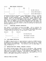
TRANSlmC 'n1B08 : fUMCTIONAL BLOCX DIAGlJJ1
TRANSTECH TMB08 USER MANUAL
PAGE 2
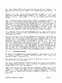
1.
INTRODUCTION
The Transtech range of TRAMs (~nsputer Modules) and motherboard provides a
flexible solution to building transputer systems, with a wide range of
processor and memory configurations.
Transtech TRAM motherboards allow TRAMs to be connected together as well as
to be connected to other transputer board products from Transtech and other
suppliers, and adhere to a published TRAM standard. This document describes
the Transtech TMB08 TRAM motherboard for IBM PC XT/AT systems and how to
install the TRAMs.
TRANSTECH TMBOB USER MANUAL
PAGE 3
TRANSTECH TMB08 USER MANUAL
PAGE 4
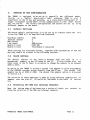
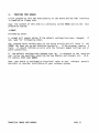
2.
HARDWARE DESCRIPTION
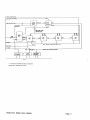
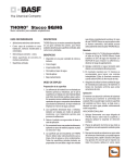
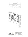
2.1
Overview
The TMB08 is a TRAM motherboard for use in an IBM PC XT/AT or compatibles.
It has slots for up to 10 daught~rboard TRAMs.
TRAMs are daughterboards
with some or all of the following:- transputers, memory, peripheral
circuitry, and they communicate with motherboards using transputer serial
links.
Each slot on the motherboard is made up from 16 DIL (Dual-in-line)
pins which provide 4 links, reset, analyse, error, power, ground, clock and
link speed selection to the TRAM. The 10 slots are arranged in a hard wired
pipeline so that links 2 to 1 of consecutively numbered slots are
pre-connected.
The remaining links can be configured using an IMSC004
crossbar switch which is supplied on the TMB08 and can be set up from a
PROGRAM running on a T212 16-bit transputer on the board. Multiple TMB08
boards can be cascaded to build larger systems, with the T212 transputers
connected in a chain to allow configuration of a network on multiple
motherboards, by sending the relevant configuration information to the
IMSC004 1 s connected to each T212 transputer.
The TMB08 also has an interface to the IBM bus so that a program on the PC
can communicate with the TRAMs on the TMBOB.
There are two options for
communication between the IBM bus and transputers, one is via software
polling of the link adaptor and the second is via a DMA mechanism which
provides a much higher data rate.
2.2
Transputer Pipeline
The TMB08 has 10 slots for TRAM daughterboards.
When fully populated with
10 size 1 TRAMs a hardwired pipeline of processors is formed with link 2
from each TRAM connected to Link 1 of the next TRAM in the chain. At the
ends of this pipeline are two links, Module 0 link 1 and Module 9 link 2
which are termed Pipehead and Pipetail resprectively.
Pipetail is taken to
the 37 way D-type connector at the edge of the board to allow it to be
connected to another transputer board.
Pipehead is taken to a 16 way patch
area on the board to allow it to be connected to various other links.
The
remaining links 0 and 3 of each TRAM slot are connected to the IMSC004
crossbar switch to allow more complicated network topologies to be built.
Further information on the programming of the C004 is provided in sections
2.4 and 6.
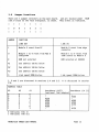
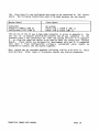
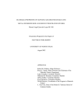
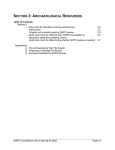
2.3 TRAM Slot Location & Pipe Jumpers
The diagram outlines the physical location of the TRAM slots on the TMB08.
It is clearly shown that adjacent TRAM slots have alternate orientation.
~
,
~
~
2
0
3
,
~
t
q
t
I
ALTERNATE ORIENTATION OF TRAM SLOTS
TRANSTECH TMB08 USER MANUAL
PAGE 5
When some TRAMs are fitted to the TMB08 which are larger than size one;- they
will physically cover more than one TRAM slot. A larger TRAM will only take
signals from one slot but will take power and ground from adjacent slots.
The hardwired pipeline will be broken on adjacent slots when a size 2 or
larger TRAM is fitted.
Transtech1s TRAMs follow two design rules to overcome this problem. The
first is to use 8 way connectors, called pipe jumpers, supplied with the
TMB08 motherboard.
TRAMs can be stacked on top of some of the TRAMs as the
signals from the motherboard slot below are propogated through to a further
set of DIL pins on top of the TRAM. When stacking of TRAMs is not necessary
or not required, a pipe jumper needs to be inserted at one end of the TRAM
covering the unused slot. This pipe jumper connects links 1 and 2 on the
unused slot to continue the hardwired pipe.
The pipe jumper needs to be
orientated so that its yellow dot aligns with the white dot on the
motherboard, indicating pin 1 of the TRAM slot.
Some of Transtech1s TRAMs have a height profile which does not easily allow
stacking of TRAMs.
These TRAMs incorporate the pipejumper connectors onto
the PCS, so that all unused TRAM slots underneath them already have their
link 1 and 2 connected, when the TRAM is inserted, to complete the hardwired
pipeline.
2.4
IMSC004 Crossbar Switch Control
The IMSC004 crossbar switch allows software control of the topology of the
transputer network.
The C004is a 32 way link switch with 32 link inputs
and outputs and is configured via a configuration link.
Links 0 and 3 from
TRAM slots 1 to 9 and link 3 from TRAM slot 0 are directly connected to the
C004.
There are ten other links connected to the C004, two of these go to
the 16 way patch area and eight to the 37 way edge connector and are
designated Edge Link 0 to Edge Link 7 respectively. TRAMO linkO can also be
connected to the C004 if required, but only via the patch area.
This
enables TRAMO linkO to be connected to the PC via the IMSC012 link adaptor
which also terminates at the patch area.
Full details on setting up the
patch connectors are to be found in section 3.7.
There are two methods of programming the IMSC004. Firstly,
link of the IMSC004 is programmed from an IMST212 16-bit
IMST212 has link 3 connected to the C004, and uses links 1
and transmit configuration information.
Link 1 is termed
2 configdown.
the configurationtransputer.
The
and 2 to receive
configup and link
Configdown goes to the 37 way edge connector to be conncted to the next
board in the chain, while configup goes to the patch area to allow the
The IImaster or
source of the configuration information to be selected.
first board in the chain has its configup connected to Pipehead (TRAM 0 link
1) for information to be down loaded fron the TDS running on the root
In this way a PROGRAM for a network of T212 transputers can be
processor.
down loaded to program all C004 s as required.
ll
1
TRANSTECH TMB08 USER MANUAL
PAGE 6
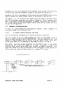
Secondly, the IMSC004 can be programmed via a link from a link adaptor,
memory mapped into the PC bus.
This method requires a second link adaptor
to be installed on the board in a spare socket marked C012(2) above the
other IMSC012 which provides the PC interface to TRAM slot O.
The IMST212 needs to be removed and the link from the link adaptor (2) needs
to be connected to the C004 crossbar switch. The link from link adaptor (2)
is connected to link 0 of the T212, and link 3 of the T212 is connected to
the configuration of the C004.
Hence with the T212 removed, link 0 on the
T212 socket needs to be connected to link 3. These connections are shown in
the diagram below.
10
A
CONNECT PIN AS TO B7
AND PIN 85 TO A9
B
c
o
G
H
K
Once the hardware adjustments have been made, the Pascal program supplied on
the floppy disk can be edited and compiled to set up the relevant
connections on the C004. The program can be included in a batch file on the
PC to allow the transputer network configuration to be set up without the
need to use the TDS.
Further details on the software provided to support
programming the C004 are contained in Section 6.
2.5
both
techniques of
System Services (Reset, Analyse & Error)
Transputers in a system as well as having links connected together must also
have system services connected to control the resetting and analysis of
errors in the system.
The TRAM in slot 0 can either be reset by the PC bus
or by another board via the 37 way edge connector.
When the TRAM on slot 0
is reset from the PC bus, it can also be analysed by the PC bus as well as
having any error ready by the PC bus.
All of these functions can also be
controlled via the 37 way edge connector.
TRAMs in slots 1 to 9 can either be controlled by the same source as TRAM 0,
(PC bus or 37 way edge connector) or from the subsystem port of TRAM O. The
subsystem port allows TRAM 0 to control the reset, analyse and error
functions of TRAMs 1 to 9.
TRANSTECH TMB08 USER MANUAL
PAGE 7
The selection of the source of system services is detailed -in section-- 3.5,
and discussed in the example board configuration in section 3.7.
2.6
The IBM Bus Interface
The IBM interface consists of 3 elements, 2 link adaptors systems (1 of
which is optional) and a BIOS EPROM which sits at IDOOOX in the IBM memory
map and is 32KBytes long.
The link adaptor systems are for communication between the PC bus and
transputer network and optionally a method of programming the C004 crossbar
switch as discussed in section 2.4.
The EPROM is not supplied as standard, but by adding it to the available
socket on reset of the PC the ROM code can be read and acted upon. This can
be useful for end user systems, where the user may not know about transputer
systems, but has a developed software package running on the supplied
hardware.
There are two ways to use the link adapator(l) (IMSCOI2) to communicate
between the PC bus and transputer system, described in the following two
sections.
2.6.1
Polling the Link Adaptor
This method is the simplest form of data transfer between the PC bus and the
TMB08.
Earlier Transtech boards used only this method and the TMB08 is
totally compatible with them.
It is often referred to as a 11 B004 11
interface.
The status of the registers of the IMSC012 are continuously polled by
software running on the PC.
Further details are contained in the IMSC012
data sheet which is included in the Transputer Reference Manual, available
from Prentice Hall. Before any data can be sent to the TMB08, it must first
be reset by software.
2.6.2
Direct Memory Access (DMA)
The data rate for polling the link adaptor is slow.
This is why a DMA
interface facility has been developed for the TMB08 to satisfy demands for
higher data rates.
This technique uses the 8237 DMA controller chip in the PC, details of which
can be found in the 8237 data sheet.
The DMA interface can be used in different ways, once the 8237 has been
initialised. A transfer to the TMB08 is started by the program running on
the PC writing a 0 to the DMA control register of the TMB08. A 111
is
written to the PC to receive data from the TMB08.
11
The TMB08 makes a DMA request for a single byte at a time, so a byte is
transferred between the execution of each instruction on the PC.
Hence the
TRANSTECH TMB08 USER MANUAL
PAGE 8
PC appears to be running code at the same time as the DMA transfer is taking
place.
The end of the DMA transfer is signalled by either the 8237 being
polled by reading its status register, giving information about which DMA
channels have a transfer pending and which have completed transfers, or by
an interupt being set up.
Further details on interupts appear in the next
section.
2.6.3
#
Interupts
There are four sources of interupt that the TMB08 can use to signal to the
PC.
1.
2.
3.
4.
Interupt
Interupt
Interupt
Interupt
on
on
on
on
end of DMA transfer
transputer error
link data input ready
link data output ready
The interupt control register is used to determine which of these events
cause an interupt.
Four bits are used in this write only register (see
section 2.6.4).
Writing a 111 11 to a bit interupts on the relevant event and
a 110 11 disables the interupt.
To determine the source of an interupt it is required to read status
regi sters. The error flag Output Int and Input Int are status 1 inks
bits present in the TMB08 registers, while the interupt on DMA end can be
detected by reading the 'status register of the 8237 DMA controller in the
PC.
I
2.6.4
TMB08 Interface Registers
The registers of the TMB08 are located in the PC I/O address space detailed
below.
Board Address
Register
boardbase + #00
boardbase + H01
boardbase + H02
boardbase + H03
boardbase + #10
boardbase + #11
boardbase + #10
boardbase + #12
boardbase + #13
Input data register
Output data register
Input status register
Output status register
Reset register (write only)
Analyse register (write only)
Error location (read only)
DMA request register
Interupt control register
Boardbase is the base address and can be #150 or #200 as detailed in section
3.2.
The function
data sheet.
of the first four registers is also detailed in the
TRANSTECH TMB08 USER MANUAL
PAGE 9
IMSC012
The others which a specific to the TMB08 are detailed here:
Reset Register (Write Only)
Writing bit 0 : to 111
11
asserts Reset: to 110 11 desserts.
Analyse Register (Write Only)
Writing bit 0 : to 111 11 ass~_rts Analyse: to 110 11 desserts.
Error Register (Read Only)
Reading bit 0 : as 111 11 indicates Error: as 110 11 no error.
DMA Request Register (Read/Write)
Writing bit 0 : as 110 11 indicates DMA from PC to TMB08
: as 111 11 indicates DMA from TMB08 to PC
IRQ control register (Write Only)
Four bits are used to control the function of the register.
Writing 111 11 to bit 0 enables interupt on end of DMA.
Writing 111 11 to bit 1 enables interupt on error.
Writing 111 11 to bit 2 enables interupt when TMB08 is ready to receive
byte.
Writing 111 11 to bit 3 enables interupt when TMBOB is ready to transmit
byte.
Writing 110 11 to any bit disables the interupt.
2.7
The Patch Area
The Patch Area is a 16 pin DIL header block which has 8 links terminating at
it.
(A link consists of two wires).
These 8 links allow different
configurations to be set up for the TMB08 to be used as a "mas ter or
IIslave" board. The links are:
ll
TRAM slot 0 link 0
IMSCOI2(l)
Pipehead
Configup
Patch link 0
Patch link 1
C004 link 28
C004 1ink 29 .
The options on connecting these links are detailed
section 3.7 showing example conf~gurations.
2.8
in
the
configuration
Link Speeed Selection
The link speed of all links on the TMB08 is selectable for
MBits/sec and is detailed in the configuration section 3.4.
TRANSTECH TMB08 USER MANUAL
10 or 20
PAGE 10
3.
SETTING UP THE CONFIGURATION
The TMBOB is designed to be set up in generally two different modes,
firstly, as a IIMaster board with a IIroot processor TRAM in slot 0
interfaced to the PC bus and secondly, as a slave board forming part of a
larger transputer system where all the communication is with other boards
and not the PC. The various configurations and options are set up using
different jumpers on the board.
ll
3.1
ll
Default Settings
The boards default configuration is to be set up as a Master board and this
is how the TMB08 will be supplied from Transtech.
Boardbase address
Interupt channel
DMA channel
Link Speed
Module 0 reset
Module N reset
#150
3
1
20Mbits/sec
FROM IBM
from Module 0 subsystem
These settings are discussed further, together with explanations of how and
why they should be altered in the following sections.
3.2
Board Address
The default address of the board is between #150 and #163 (# is a
hexadecimal number) in the I/O space of the PC.
If this clashes with any
other cards in the PC there is an option to change the address to be between
#200 to #213.
An option of the TMBOB is to have a second link adaptor to allow programming
of the IMSC004 crossbar switch directly from the PC bus.
This second link
adaptor can be at #250 or #300. The second link adaptor option is discussed
in section 2.4.
The selection of these addresses is made by using different combinations of
jumpers over the pins AI, A2 and A3 as indicated in the table in section
3.6.
3.3
Selecting the DMA and Interupt Channels
Near the bottom edge of the board are a series of single pin
allow the selection of the DMA and interupt channels.
TRANSTECH TMB08 USER MANUAL
sockets to
PAGE 11
3.3.1
DNA
Channel Selection
1
DRQ
2
1
DMA
2
*
*
*
*
*
*
*
*---------*
*
*---------*
*
*---------*
*---------*
*
No DMA selection
Selects DMA Channel 1
Selects DMA Channel 2
The default setting of the board is to use DMA Channel 1 which is available
on both PC AT and XT systems.
However, DMA channel 1 is often u~ed for
ethernet or other networking cards.
DMA channel 2 is the floppy disk DMA
channel, which can be disabled by writing I/O to memory location #3F2,
allowing it to be used by the TMBOB for data transfer.
Whenever a floppy
disk access is required, the disk BIOS always enables location #3F2, this
means that the TMBOB driver must disable location #3F2 and enable its
drivers at the start of a DMA transfer, and then disable its drivers at the
end of a transfer. Separate software routines are provided for handling the
different DMA channels.
Interrupt Channel Selection
3.3.2
IRQ channel 3 is the default setting of the TMBOB.
This is normally the
setting for a second RS232 port, while the other option IRQ channel 6 is
associated with the diskette driver.
The software routines for DMA channel
1 support IRQ3 and the routines for DMA channel 2 support IRQ6.
Channe13
IRQ
Channe16
*
*
*
*
*------------*
*-----------*
*
3.4
No IRQ Selection
IRQ Channe13 selected
IRQ Channe16 selected
Link Speed Selection
The TMBOB is -supplied with all links running at a default of 20Mbits/second.
To change the links running at 10Mbits/second a jumper needs to be inserted
between the two pins marked IISII. This affects all links on the T212, C004,
link adaptors and fitted TRAMs.
The location of the link speed jumper is
shown in section 3.6.
3.5
System Services (Reset, Analyse & Error)
The default settings assume a TRAm in slot 0 is the Master TRAM connected
via its link 0 to link adaptor (1) and hence the PC bus.
Consequnetly the
TRAM in slot 0 is reset by the PC, and the remaining TRAM on the board are
controlled from TRAM O's subsystem.
The location of the jumpers used to
control these functions is shown in section 3.6. More details are- to be
found in the example configuration in section 3.7.
TRANSTECH TMBOB USER MANUAL
PAGE 12
3.6
Jumper Locations
There are 7 jumper selectors on the main board, and are located under TRAM
slot 9 close to the T212 transputer, as shown. They select as indicated.
*
*
*
*
*
I
*
o
R
1
2
3
S
*
*
*
*
*
*
*
*
JUMPER
FUNCTION
LINK OUT
LINK IN
I
Module 0 reset from PC
Module 0 reset from edge
connector
0
Module 1 to 9 reset from Mod 0
SubSystem
Module 1 to 9 reset from
same source as Module 0
R
ROM not selected
ROM selected at #DOOOX
Al
See address tables below
A2
See address tables below
A3
See address tables below
S
Link speed 20Mbits/sec
Link speed 10Mbits/sec
I, 0 and S are discussed in sections 3.4 and 3.5.
2.6.
R is discussed in section
ADDRESS TABLE
A3
A2
Al
0
0
0
0
0
0
1
0
1
0
1
1
1
0
0
0
I
1
1
1
1
1
0
1
boardbase L/A(2)
boardbase L/A (1)
(optional link adaptor)
#200
#250
#250
#200
#300
#200
#300
#150
#300
#150
-
o indicates link in
I indicates link out
TRANSTECH TMBOB USER MANUAL
PAGE 13
Boardbase L/A (1) is the address of the IMSC012 which provides the interface
to the PC bus from the transputer system as discussed in section 3.2.
Boardbase L/A (2) is the address of the second optional IMSC012 which can be
used to program the C004 crossbar switch as discussed in section 2.4.
,-
The jumper I, 0, AI, A2 and A3 also appear near the edge of the board above
the 37 way D-type connector as a series of headers.
These headers have
small link jumpers on one pin equivalent to jumper link out as the default.
It is often easier to use these jumpers rather than the ones under slot 9 to
set up the configuration.
3.7
Example Configurations
To help in understanding the configuration options,
configured TMB08 1s are discussed here.
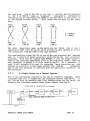
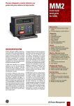
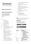
3.7.1
three examples of
A Single Board Running the TDS
This is the default configuration in· which the board is supplied.
The TDS should be run on a TRAM plugged into slot 0 of the TMB08, with a
server program running on the PC under MS.DOS. The two communicate via link
adaptor I, memory mapped onto the PC bus at either #150 or #200, which goes
to the patch where it is connected to the TRAM in slot 0 via link o.
The reset, error and analyse functions for the TRAM in slot 0 are under
control from the PC bus (i.e. jumper 111 11 is out).
The TRAM1s in slots 1 to
9 and the T212, derive their reset under control of TRAM01s subsystem. This
means that TRAMO can reset and analyse all the transputers in the system as
well as read the status of their error (i.e. jumper 110 is out).
11
A SINGLE BOARD RUNNING THE TDS
0
. -_ _
LI_NK--4
TRAMO
LINK2
RESET
ANALYSE
& ERROR
LINK 1 TRAMl
. LINK2
LINK 1
TRAM2
LINK2
RESET. ANALYSE AND ERROR FOR TRAMS 1 TO
_ .. _ LINK 1
TRA~19
9- ..···
PC BUS
TRANSTECH TMB08 USER MANUAL
PAGE 14
The "config up" link of the T212 is its link 1, and this must be connected
to link 1 of TRAM 0, known as pipehead
Consequently, configuration
information can be down loaded from TRAMO to the T212 which in turn passes it
to the IMSC004 crossbar switch.
These connections are made via the patch
area.
ll
II
PATCH
LINK 1
I
0
PATCH
LINK 0
I
0
•
C012
LINK 1
I
0
T2112
LINK 1
I
0
o = OUTPUT
I
I
C004
LINK 28
0
I
0
C004
LINK 28
I
TRAMO
LINK 1
0
0
=
INPUT
I
TRAMO
LINK 0
The other connections made on the patch area are Patch Link 0 and 1
connected to C004 links 28 and 29, which provide two more (making 10 in all)
link connections from the C004 to the edge connector.
This configuration allows the TDS to run on the root processor and download
code to a network of target processors controlled by the root processors
subsystem.
Each time the command LOAD NETWORK is used the target system is
reset by the subsystem immediately prior to the code betng loaded. When the
root processor is booted it is first reset by the PC.
As a processor is
reset it will automatically reset its subsystem, hence preventing any code
running on processors in the target network from sending
unexpected
data to the root processor to interfere with the application running on the
root processor.
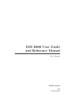
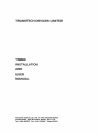
A Single Board as a Target System
3.7.2
This is the configration required to run the 3L scientific languages, where
a bootable code file is loaded onto the transputer network from the pc.
It
can also be used for bootable code files produced using the TDS which are
loaded to the transputer network under server support from the PC.
A SINGLE BOARD AS A TARGET SYSTEM (3L LANGUAGES)
a---_ _
L1-NK-;O
TRAMO
F=I:.:.:.:.NK;:.;:..2_
.....
I .......
NK~l
TRAMl
r-;,:I::..:.:.;NK;.;.;;;.2
1 TRAM2
L-...-IN........
K'""-1
INK2
••
INKl
TRAM9
PUS BUS
TRANSTECH TMB08 USER MANUAL
PAGE 15
The link between TRAM 0 Link 0 and the PC bus via the Link adaptor 1 is
maintained from the previous example as the communication route between the
two.
However, the reset analyse and error functions of TRAMs 1 to 9 are now
controlled from the same source as TRAM 0, i.e. the PC bus.
This means
jumper 0 is now in, while jumper"111 is still out allowing control from the
PC bus.
11
This configuration means that a reset to TRAM 0 is propogated directly to
TRAMs 1 to 9 and the T212 without going via the subsystem of TRAM O.
The
same effect can be achieved in the configuration in 3.7.1 where the reset is
propogated via the subsystem hence the PC resets all the transputers at
once.
The difference with this new configuration is that the PC can also
analyse all the TRAMs at once and not just TRAM 0, and that the PC can
monitor the error status of all the transputers whose error signals are
logically ORld together, rather that just the error status of TRAM O.
3L l s languages can be run on the configuration in 3.7.1. but in that case it
is not possible to receive errors from TRAMs other than TRAM 0 or to analyse
TRAMs other than TRAM O.
Since the TDS cannot reset the T212 immediately before down loading code to
configure the T212 in this configuration, it is suggested that the C004
crossbar switch is programmed by the Turbo Pascal program running on the PC
addressing the link adaptor 2 as discussed in section 2.4.
The patch
connection between TRAM 0 link 1 and the T212 link 1 can remain, but since
the T212 is removed that connection will not be used.
The link adaptor (2)
will be connected directly to the C004 by means of connections made to the
T212 socket as shown below.
The link adaptor 2 can be at boardbase address
#250 or #300 and is selectable by reference to the table in section 3.6.
The registers for link adaptor 2 are the same as for link adaptor 1 as
described in section 2.6.4 except that the boardbase address is different.
Cascaded Boards
3.7.3
An example of two TMBOB boards cascaded together is described here. The TDS
is running on TRAM 0 of a IImaster board and another s lave board with
additional TRAMs is connected to it.
ll
II
ll
The master board should be set up exactly as detailed in section 3.7.1
the TDS running on a single board.
for
The "s 1ave board 'should be invisible to the PC bus, with its link adaptor
and system registers disabled. This is achieved by removing the connections
between TRAM 0 link 0 and link adaptor 1.
ll
TRAM 0 link 1 on the slave board should be connected to TRAM 9 link 2 on the
IImaster to continue the IIlink 2 to link 111 hardwired pipeline discussed in
section 2.2.
This is why TRAM 0 link 1 is known as IIpipehead
To enable
this connection TRAM 0 link 1 should be connected to Patch link 1 on the
patch area.
ll
ll
•
TRANSTECH TMBOB USER MANUAL
PAGE 16
TWO CASCADED BOARDS
LINKO
TRAMO
RESET
ANALYSE
K-t
1
.....I_NK_2_ _L_IN_
TRAMl
~LI~NK;.;.;;;;..2----.-.;L~IN_K~l
SUBSYSTEM
& ERROR
t------a.-------~
TRAM2
LINK2
INK2_o_ - ..
TRAN9
..-._------.---. -_.- --.-
RESET, ANALYSE AND ERROR FOR TRAMS 1 TO 9
PC
SUBSYSTEM
UP
BUS
PIPETAIL
PIPEHEAD
LINKl
TRAMO
t-I_NK~2_.;;;;LI;.;;.;.;.NK~l
TRAMl
LINK2
LINKI
TRAM2
.IINK2
__ _ _
LINKl
TRAM9
RESET, ANALYSE AND ERROR FOR TRAMS 0 TO 9
To allow the configuration of the slave board to be programmed from the
master board the T212 link 1 (lI config Upll) should be connected to the patch
link 0 on the patch area, to allow it to be connected to the T212 on the
master board via config down on the masterboard1s edge connector.
The final adjustment to the patch area is not necessary but may be useful
and allows an extra link to be connected to the C004, i.e. TRAM 0 link 0 to
C004 link 28.
Hence the patch area should be configured as follows:
PATCH
LINK 0
0
I
PATCH
LINK 1
I
0
T212
LINK 1
I
0
C012
LINK 1
0
I
= OUTPUT
I = INPUT
0
0
I
COO4
LINK 28
0
I
COO4
LINK 29
0
I
TRAMO
LINK 1
I
0
lRAMO
LINK 0
TRAMO should derive its system services control from the "uP" on the 37 way
edge connector, hence jumper I should be in.
TRAMs 1 to 9 and the T212
should also receive control from the "UP" so jumper 0 should be in too.
TRANSTECH TMB08 USER MANUAL
PAGE 17
The slave board is now configured and ready to be connected to the master
board. The following connections need to be made between the two boards.
Master Board
Subsystem
Pipetail (TRAM 9 LINK 2)
Config Down (T212 LINK 2)
Slave Board
~
Up system
Patch link 1 (TRAM 0 LINK 1)
Patch link 0 (T212 LINK 1)
The pin out of the 37 way D-type edge connector is given in appendix A. The
pin out of an adaptor board which converts the 37 way connector to the
standard Inmos 5 way connectors for links and system services is in appendix
B, to allow the supplied cables to be used to make the connections between
boards.
These cables are designed for development only and it is suggested
that when a final configuration is known a customised cable should be
assembled to connect the two boards together.
More boards may be cascaded together following similar principles to these
detailed here. Other types of transputer boards can also be connected.
TRANSTECH TMB08 USER MANUAL
PAGE 18
4.
INSTALLATION
4.1
TRAM Fitting and Handling
Care must be taken when fitting or removing TRAMs from the TMBOB, to ensure
no damage occurs to the TRAM pins.
A white circle in the corner of each
TRAM slot indicates Pin 1 of that slot on the TMB08.
TRAMs also have an
indicator for pin 1, which should be matched with the marking on the
motherboard to ensure correct orientation.
A TRAM plugged in the wrong way
round may result in damage to the TRAM and the motherboard.
The TMB08 has some components mounted on the board between the TRAM sockets,
which foul some of the TRAMs available. These can effect TRAM slots 6, 7, 8
and 9.
If a TRAM cannot be fitted without fouling these components, stand
off strips or larger pins supplied with the TRAM should be fitted to allow
the TRAM to be raised above these components.
4.2
Installing a TMB08
Remove the TRAM that is to be the root processor from its protective
packing, observing the appropriate anti-static handling precautions. If the
TRAM is to run the TDS its subsystem pins will need to be connected to the 3
sockets marked E.R.A. (Subsystem) near to Pin 1 on TRAM slot 0 of the TMB08.
This is achieved using a 3 pin 2 way header supplied with the TMB08 or in
some cases with the TRAM.
You may also need, depending on the TRAM or
length of subsystem pins, to use a ~ way spacing strip supplied with the
TMB08.
The 3 pin header (subsystem pins) fit into 3 sockets on the
underside of the TRAM near Pin 1 so that when the TRAM is fitted to the
board the 2 way header makes a connection between the subsystem sockets on
the TRAM and the TMB08.
N.B. The subsystem pins are only needed if the Subsystem of TRAM 0 is needed
to control other TRAMs in the system. Refer to section 3.7 and the example
configurations.
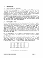
Plug the TRAM into slot 0 ensuring pin 1 matches pin 1 on the TMB08. The 16
pins that carry the signals should fit into the required slot, so a TRAM
larger than size 1 that fits over more that one slot will cover adjacent
slots to TRAM slot 0, i.e. a size 1 TRAM will cover slots 0 and 3 and a size
4 TRAM will cover slot 0, 3, 6 and 8 as shown in the diagrams below.
~
I
~
5
2
0
~
~
3
G
~
~
9
~
I
I
A SIZE 2 TRAM FITTED TO SLOT 0 WITH PIPE JUMPER IN SLOT 3
TRANSTECH TMB08 USER MANUAL
PAGE 19
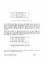
t=-
t=-
,
if-
2
S
0
3
6
~
9
~
-===:J
~
I
I
A SIZE 4 TRAM FITTED TO SLOT 0 WITH PIPE JUMPERS IN SLOTS 3, 6 AND 8
If the TRAM is larger than size 1 insert link jumpers in the slots that do
not carry signals to ensure the continuity of the hardwired pipeline.
A
jumper is an B way connector that connects link 1 to link 2 on a slot· that
does not carry any signals, and should be inserted at one end of the slot
with its indicator lining up with the Pin 1 index of the slot. If a TRAM is
stacked on top of it the jumpers need to be removed from the slots used for
stacking.
Install other TRAMs as required in the other slots of the TMB08, not
necessarily in order, provided that the pipeline is maintained as discussed
in section 2.2.
Pipe jumpers should also be fitted in the slots that are
not being used as shown in the following diagram where slots 5 and 9 have
been jumped out to complete the pipeline.
i===:II
c=::..
t:::=::II
1I
I
I
Jt
5
-=:=I
l:l
L~
0
3
6
-=:=I
g
"1
9
IIlr..
I
I
SIZE 2 TR~S FITTED TO SLOTS 0, 1 AND 8, AND SIZE 1 TRAMS IN
SLOTS 2 AND 7. SLOTS 5 AND 9 ARE JUMPED OUT. PIPE JUMPERS
ARE ALSO IN SLOTS 3, 4 AND 6.
Once all the TRAMs have been fitted follow the instructions
manual for installing an option board.
TRANSTECH TMBOB USER MANUAL
in your PC
PAGE 20
5.
TESTING THE BOARD
A test program to test the functionality of the board and the IBM
is supplied on floppy disk.
interface
Copy the content of this disk to a directory called TMBOB and run the test
program by typing:
:>test
followed by enter.
A prompt will appear asking if the default settings have been
not, type Un" followed by enter.
changed,
if
The program tests various parts of the board briefly and will check if the
TMB08 has been set up and installed correctly.
If the program reports a
fault, it should indicate an error with the relevant jumper settings and or
patch connections.
If the default settings have changed type "y" in response to the question
and follow the questions inserting the new address and channels etc. (N.B.
for address #200 type $200)
Once your board is confirmed as functional refer to your software manuals
and start to consider installation of your software system.
TRANSTECH TMBOB USER MANUAL
PAGE 21
TRANSTECH TMBOB USER MANUAL
PAGE 22
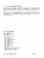
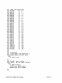
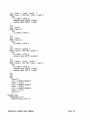
6.
C004 CONFIGURATION SOFTWARE
There are example programmes supplied on the floppy disk to demonstrate the
possible ways to configure the C004 on the TMBOB board. These programs are
listed here.
Please refer to section 2.4 to decide which program you will
use.
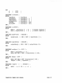
Firstly, there is an Occam PROGRAM which is intended to be compiled for the
T212 which can be extended to cover any number of T212 s in a chain of
cascaded boards.
This example can be used as a template to set up for any
C004 configuration.
1
C004 Occam PROGRAM
{{{ se e004set.tsr
{{{F C004set.tsr
PROC e004.from.T2.set ()
{{{
INT
{{{
{{{
VAL
VAL
VAL
VAL
VAL
VAL
VAL
VAL
}}}
declarations
A, B :
constants
link declarations
LinkOOut IS 0:
LinklOut IS 1:
Link20ut IS 2:
Link30ut IS 3:
LinkOIn IS 4:
LinklIn IS 5:
Link2In IS 6:
Link3In IS 7:
CHAN OF BYTE to.C004, from.C004:
PLACE to.C004 AT Link30ut:
PLACE from.C004 AT Link3In:
}}}
TRANSTECH TMB08 USER MANUAL
PAGE 23
{{{
VAL
VAL
VAL
VAL
VAL
VAL
VAL
VAL
VAL
VAL
VAL
VAL
VAL
VAL
VAL
VAL
VAL
VAL
VAL
VAL
VAL
VAL
VAL
VAl
VAL
VAL
VAL
VAL
VAL
VAL
VAL
VAL
e004 link definitions
Unused1
IS 0:
Mod1l0
IS 1:
Mod2l0
IS 2:
Mod3LO
IS 3:
Mod4LO
IS 4:
Mod5LO
IS 5:
Mod6LO
IS 6:
Mod7LO
IS 7:
Mod8LO
IS 8:
Mod9LO
IS 9:
ModOl3
IS 10
Mod1L3
IS 11
Mod2L3
IS 12
Mod3L3
IS 13
Mod4L3
IS 14
Mod5L3
IS 15
Mod6L3
IS 16:
Mod7L3
IS 17:
Mod8L3
IS 18
Mod9L3
IS 19
EdgelO
IS 20
EdgeL1
IS 21
EdgeL2
IS 22
Edgel3
IS 23
EdgeL4
IS 24
EdgeL5
IS 25
EdgeL6
IS 26
EdgeL7
IS 27
C004L28
IS 28
C004L29
IS 29
Unused2
IS 30
Unused3
IS 31:
Hi
{{{ procedures
{{{ output.byte ( VAL BYTE byte)
PROC output. byte (VAL BYTE byte)
SEQ
to.C004 ! byte
·
·
}}}
{{{ funcO ( input, output)
PROC funeO ( VAL-INT input, output)
SEQ
to.C004 ! BYTE 0
output. byte (BYTE input)
output. byte (BYTE output)
·
·
}}}
TRANSTECH TMB08 USER MANUAL
PAGE 24
{{{ fune! ( link!, link2 )
PROC fune! ( VAL INT link!, link2 )
SEQ
to.C004 ! BYTE 1
output.byte (BYTE linkl)
output.byte (BYTE link2)
··
III
{{{ fune3
PROC fune3 ()
SEQ
to.C004 BYTE 3
··
}}l
{{{ fune4
PROC fune4 ()
SEQ
to.C004 ! BYTE 4
··
III
{{{ funeS ( output )
PROC fune5 ( VAL INT output )
SEQ
to.C004 ! BYTE 5
output. byte (BYTE output)
..
}l}
{{{ fune6 ( link!, link2 )
PROC fune6 ( VAL INT link!, link2 )
SEQ
to.C004 ! BYTE 6
output.byte (BYTE link!)
output.byte (BYTE link2)
·
tB
SEQ
fune4 ()
A,B := ModlLO,ModlL3
fune! ( A,S )
A,S := Mod2LO,EdgeL7
fune! ( A,B )
A,B := ModOL3,Mod2L3
func! ( A,B )
func3 ()
.
PLACED PAR
PROCESSOR 0 T2
C004.from.T2.set ()
TRANSTECH TMBOB USER MANUAL
PAGE 25
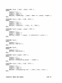
Secondly, there is a Pascal programme which can be run on the PC and access
the C004 directly via link adaptor (2). This programme can be used as a
template, edited and re-compiled to produce a programme to configure the
C004 as required.
This programme could be included in a batch file to set
up the required configuration at the start of a given application run.
C004SET.PAS Pascal programme
CONST
boardbase
inputData
outputData
inputStatus
outputStatus
resetM2
analyseM2
INTEGER = $0300
INTEGER = 0
INTEGER = 0
INTEGER = 0
INTEGER = 0
INTEGER = 0
INTEGER = 0
Unused1
Mod1LO
Mod2LO
Mod3LO
Mod4LO
Mod5LO
Mod6LO
Mod7LO
Mod8LO
Mod9LO
ModOL3
Mod1L3
Mod2L3
Mod3L3
Mod4L3
Mod5L3
Mod6L3
Mod7L3
Mod8L3
Mod9L3
EdgeLO
EdgeL1
EdgeL2
EdgeL3
EdgeL4
EdgeL5
EdgeL6
EdgeL7
C004L28
C004L29
Unused2
Unused3
BYTE
BYTE
BYTE
BYTE
BYTE
BYTE
BYTE
BYTE
BYTE
BYTE
BYTE
BYTE
BYTE
BYTE
BYTE
BYTE
BYTE
BYTE
BYTE
BYTE
BYTE
BYTE
BYTE
BYTE
BYTE
BYTE
BYTE
BYTE
BYTE
BYTE
BYTE
BYTE
·
-
.
·
TRANSTECH TMB08 USER MANUAL
{ TMB08 REGISTERS }
0
1
2
3
4
5
=6
= 7
= 8
= 9
= 10
= 11
= 12
= 13
= 14
= 15
= 16
= 17
= 18
= 19
= 20
= 21
= 22
= 23
= 24
= 25
= 26
= 27
= 28
= 29
= 30
= 31
=
=
=
=
=
=
PAGE 26
VAR
A
B
BYTE
BYTE
PROCEDURE initconst
BEGIN
inputData
outputData
inputStatus
outputStatus
resetM2
analyseM2
END
:=
:=
:=
:=
:=
:=
boardbase ,"
boardbase +
boardbase +
boardbase +
boardbase +
boardbase +
PROCEDURE initC012
BEGIN
PORT [ inputStatus]
PORT [ outputStatus]
END ;
1
2
3
;
$10;
:= 0
:= 0
$11;
{ Disable inputInt }
{ Disable inputlnt }
FUNCTION dataPresent : BOOLEAN ;
BEGIN
dataPresent := ODD ( PORT [ inputStatus ] )
END;
FUNCTION outputReady : BOOLEAN ;
BEGIN
outputReady := 000 ( PORT [ outputStatus ])
END;
PROCEDURE QutByte ( b : BYTE ) ;
BEGIN
PORT [ outputOata ] := b ;
WHILE NOT 000 ( PORT [ outputStatus ] ) DO
END ;
FUNCTION inByte : BYTE ;
BEGIN
WHILE NOT ODD ( PORT [inputStatus] ) DO
inByte := PORT [ inputOata ] ;
END;
PROCEDURE loopFor (i
INTEGER)
BEGIN
WHILE ; <> 0 DO ; := ;-1
END ;
TRANSTECH TMBOB USER MANUAL
PAGE 27
PROCEDURE funcO (input, output BYTE)
BEGIN
outbyte ( 0 ) ;
outbyte ( input ) ;
outbyte ( output ) ;
WRITELN ( tConnecting : l,input,1 input. To l,output,1 output l )
END
PROCEDURE func! ( link! , link2 ~ BYTE) ;
BEGIN
outbyte ( ! ) ;
outbyte ( linkl ) ;
outbyte ( link2 ) ;
WRITELN ( IConnected : t ,1inkl,1 to I, link2 )
END
PROCEDURE func2 ( output , answer BYTE)
BEGIN
outbyte ( 2 ) ;
outbyte ( output ) ;
answer := inbyte
WRITELN (Ioutput : 1,0utput,1 is connected to I,answer )
END
PROCEDURE func3
BEGIN
outbyte ( 3 ) ;
WRITELN (IC004 SET
END ;
I
)
PROCEDURE func4
BEGIN
outbyte ( 4 ) ;
WRITELN (IC004 RESET I )
END ;
PROCEDURE func5 ( output : BYTE )
BEGIN
outbyte ( 5 ) ;
outbyte ( output ) ;
WRITELN (IDisconnecting output: I,output )
END
PROCEDURE func6 ( linkl , link2 : BYTE) ;
BEGIN
outbyte ( 6 ) ;
outbyte ( linkl ) ;
outbyte ( link2 ) ;
WRITELN (I Disconnecting link
I ,link!,· from l,link2 )
END
TRANSTECH TMB08 USER MANUAL
PAGE 28
PROCEDURE doReset ;
BEGIN
PORT [ analyseM2 ] := 0
100pFor ( BOO)
PORT [ resetM2 ] := 1
100pFor (3000)
PORT [ resetM2 ] := 0
100pFor (1000)
END ;
PROCEDURE clearError
BEGIN
doReset ;
initC012 ;
outByte (4) ;
outByte ($22)
END ;
PROCEDURE SetError
BEGIN
doReset ;
initC012 ;
outByte (6) ;
outByte ($22)
outByte ($FB)
END
.
t·
outbyte ($F9)
outByte ($60)
outByte ($F9)
outByte ($21)
outByte ($25)
outByte ($FO)
outByte ($OE)
PROCEDURE loadT2code ;
VAR
data
: BYTE ;
bootcode : FILE OF BYTE
BEGIN
ASSIGN ( bootcode , Ilistener.m2
RESET (bootcode);
WRITELN ( ILoading bootcode to transputer ... I)
REPEAT
READ ( bootcode , data )
outByte ( data ) ;
UNTIL EOF ( bootcode ) = TRUE
WRITELN ( 1 Loaded code I ) ;
END ;
1
)
;
PROCEDURE switches ;
BEGIN
boardbase := $0200
END ;
TRANSTECH TMBOB USER MANUAL
PAGE 29
BEGIN
WRITELN ( 1 SET UP FOR C004 CONFIG
switches
initconst
doreset
initC012
func4
;
B : = Mci-d3L3
A := Mod2LO
A := ModlLO
B := EdgeLO
A := EdgeL7
B := ModlL3
func3
I)
funcl ( A,B )
funcl ( A,B )
func! ( A,8 )
END.
TRANSTECH TMBOB USER MANUAL
PAGE 30
APPENDICIES
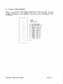
A. 37 WAY D-TYPE CONNECTOR PIN OUT
down notError
-------------19
down notReset
18
configdown out
17
pipetail out
16
notSubsystem Analyse
15
Patch link1 in
14
Patch linkO in
13
GND
12
Edge link7 out
11
Edge link6 out
10
Edge link5 out
9
Edge link4 in
8
Edge link3 in
Edge link2 in
GND
Edge link1 out
6
36
configdowm in
35
pipetail in
34
notSubsystem Error
33
notSubsystem Reset
32
Patch link1 out
31
Patch linkO out
30
Edge link7 in
29
Edge link6 in
28
Edge link5 in
27
GND
26
Edge link4 out
25
Edge link3 out
24
Edge link2 out
23
Edge link1 in
22
Edge linkO in
21
up notError
20
up notReset
5
4
3
up notAnalyse
2
TRANSTECH TMB08 USER MANUAL
down not Analyse
7
Edge linkO out
GND
37
1
--------------
PAGE 31
B. 37 WAY D-TYPE ADAPTOR
There is a D-type socket adaptor supplied to plug into the 37 way
D-type connector at the edge of the board. This adaptor enables
standard link cables to be attached. The pin outs of this adaptor are
as follows:
DOWN
SUBSYSTEM
11
10
9
8
7
6
5
4
3
2
1
o
(configdown)
(pipetail M9 L2)
(patch link 1)
(patch link 0)
(edge link 7)
(edge link 6)
(edge link 5)
(edge link 4)
(edge link 3)
(edge link 2)
(edge link 1)
(edge link 0)
UP
TRANSTECH TMB08 USER MANUAL
PAGE 32
C. REFERENCES
1. Transputer Reference Manual, Inmos Limited
Prentice Hall ISBN 0-13-929001-X
2. Transputer Technical Notes, Inmos Limited
Prentice Hall ISBN 0-13-929126-1
3. Intel 8237 data sheet, Intel Limited
TRANSTECH TMB08 USER MANUAL
PAGE 33