1
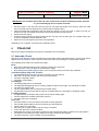
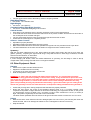
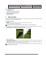
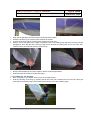
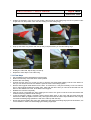
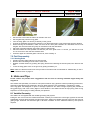
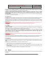
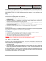
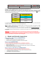
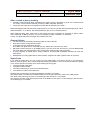
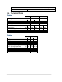
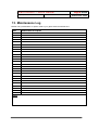
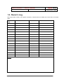
Icaro Orbiter – User’s manual 20/01/07 Page # 1/22 Edition Dec. 2006 Orbiter User’s Manual Rev. 12.06 Icaro Orbiter – User’s manual 20/01/07 Page # 2/22 Edition Dec. 2006 Congratulations on buying an Icaro 2000 hang glider! We are certain that you have made the right choice! The new Laminar represents the greatest technological advancement in its field over the last few years; hang gliding will never be the same again. Icaro 2000 srl is one of the world's leading hang glider manufacturers. The company has built over 8,000 hang gliders during the course of the last twenty-two years. Icaro 2000’s competition and sales record are the envy of other manufacturers… Icaro 2000 gliders are fully designed and manufactured in our factory at Sangiano, in Northern Italy, using exclusively top quality materials. The development of our wings reflects the commitment of Manfred Ruhmer, four times World Champion (two Cross Country titles, one Speed Gliding title and one Class V title), and our two decades of experience in hang glider manufacture. All our hang gliders have German certification (DHV). You can rest assured that spare parts and service will always be available, no matter where you fly, by means of our worldwide network of distributors. This includes spares for all models, both those in production and earlier designs. Thank you for choosing our hang gliders and we wish you great flights! For whatever information or service, please contact the nearest authorized dealer, or the factory direct: Icaro 2000 srl via Verdi, 19 21038-Sangiano, VA ITALY Ph. +39-0332-648-335 Fax +39-0332-648-Z89 e-mail: [email protected] Internet: www.icaro2000.com Icaro Orbiter – User’s manual 20/01/07 Page # 3/22 Edition Dec. 2006 Table of Contents 1. 2. 3. 4. 5. 6. 7. 8. 9. 10. 11. 12. 13. 14. INTRODUCTION 1.1 KEEP RISKS TO A MINIMUM 1.2 PRELIMINARIES 1.3 ASSEMBLY CHECK AND FIRST FLIGHT 1.4 HIGH FLIGHTS FUNDAMENTAL RULES CERTIFICATION AND GENERAL LIMITS 3.1 CERTIFICATION 3.2 WIND SPEED 3.3 TURBULENCE 3.4 AEROBATIC FLYING TRANSPORT 4.1 BY CAR 4.2 BY GONDOLA OR CABLE CAR 4.3 BY PLANE 4.4 SHORT PACKING ASSEMBLY 5.1 ON THE FRAME CHECK LIST 6.1 ASSEMBLY CHECK 6.2 OTHER EQUIPMENT CHECK 6.3 PRE-FLIGHT CHECK DISASSEMBLY HINTS AND TIPS 8.1 VARIABLE GEOMETRY 8.2 TAKE OFF 8.3 FLIGHT 8.4 LANDING TRIM 9.1 TURN TENDENCY: 9.2 TRIM S PEED REFLEX AND DIHEDRAL REPAIR AND PERIODICAL INSPECTIONS TECHNICAL DATA MAINTENANCE LOG OWNER’S LOG 4 4 4 4 4 4 5 5 5 5 5 5 5 6 6 6 6 7 10 10 11 12 12 15 15 16 16 16 16 17 17 17 18 20 21 22 Icaro Orbiter – User’s manual 20/01/07 Page # 4/22 Edition Dec. 2006 1. Introduction Over the last two decades hang gliding has become much safer. Accidents have diminished, due to the increased professionalism of flying schools, and increasingly stringent certification procedures. In Switzerland, for example, the insurance risk factor for hang gliding is the same as for winter sports. However, hang gliding is an active sport, in which there is a certain degree of risk. Your safety can be greatly enhanced by following a few simple rules: Note: The Orbiter is also available in a version with variable geometry (VG) (optional). Reference is made to this system in various parts of this manual. Its function and use is comprehensively described in Chapter 5. 1.1 Keep risks to a minimum Attend a professional school. Fly a glider suited to your skills. In order to fly the Orbiter you should be an intermediate pilot with at least 50 hours logged on another hang glider. Fly only when weather conditions are suitable. Be aware of adverse weather conditions; caution is a mark of intelligence, not of cowardice. Keep in continuous contact with your sport. Try to avoid long intervals between one flight and the next. This will also help you to progressively increase your flying skills. A new risk may arise when you fly a new type of glider for the first time. The reactions of your new glider may well differ from those of the glider you were used to. In order to minimise this risk, we recommend a gradual process of familiarisation with your new glider. Make your first flight in calm conditions. 1.2 Preliminaries Study your manual before your first flight. Practice assembly and disassembly as explained in the manual. Always follow the same assembly and pre-flight check routine; do not allow yourself to be distracted during these procedures! 1.3 Assembly check and first flight Every authorized ICARO 2000 dealer can test fly your glider. If requested, it can be test flown at the factory before delivery. We recommend this procedure: you are entitled to it. Your dealer should also help you set up your glider for the first time and see you off on your first flight. We strongly recommend speedbar wheels, especially for your first flights. 1.4 High flights For your first mountain launch, wait until weather conditions are ideal. It is best to fly in a location with which you are familiar, as long as it has a suitable launch site and landing site, in terms of both space and aerological conditions. Fly with your habitual harness and instrument. Experiment with different VG settings, roll reversals, slow flight, high speed flight and stalls at an altitude of at least 350 m (about 1,000 feet). 2. Fundamental Rules After major repairs, after replacing the sail or after a long period without flying, always choose a site to fly from that you are familiar with; and where it is possible to land immediately after take-off. Your glider is delivered to you ready to fly. WARNING: Do not make any adjustments that are not described in this manual. Icaro Orbiter – User’s manual 20/01/07 Page # 5/22 Edition Dec. 2006 Periodically check the trim values shown in the tables (Chapter IX). Fly only after having attended a good school, recognized by your hang gliding federation. This Owner's Manual does not replace the checks on serviceability performed by an authorized dealer. This is true even for expert pilots. A pilot who is in doubt about any aspect of his/her glider should consult his dealer, or ICARO 2000, for advice. Never fly alone. Before every take-off, always perform both an assembly check and a pre-flight check. Don’t push your luck! Fly only in places suited to hang gliding. It is your responsibility to be aware of the limits of your glider, and the limits of your own experience. Don’t attempt towing of any kind, unless you have attended a recognized towing school. Always fit wheels on your speedbar when towing. 3. Certification and General Limits 3.1 Certification All ICARO 2000 hang gliders have German certification (DHV). Icaro gliders are rated according to the German DHV as follows: Class 1 (beginner pilots) – Laminar RELAX and Mars Class 2 (intermediate pilots) – Laminar EZ, Orbiter Class 2-3 (advanced pilots) – Laminar 12 Master, 13 Master, Class 3 (advanced pilots) – Laminar 14 Master, Z8 12.9, Z8 13.2, Z813.7, Z8 14.1, Z8 14.8 3.2 Wind speed When the wind speed is stronger than 30 km/h (~15 knots), launch becomes risky. In these conditions, consult with more experienced pilots before launching. Trust those who advise prudence, and do not be let yourself be influenced by pilots showing excessive self-confidence or brash disregard. If in doubt, do not fly. 3.3 Turbulence In turbulent conditions, gusts of descending air can induce sudden powerful negative forces on the glider; such negative forces must be avoided. Do not fly in turbulent conditions or on the lee side of a mountain; this is extremely risky in strong winds. 3.4 Aerobatic flying Aerobatic flight includes flying with bank angles greater than 60 , pitch angles greater than 30 , whip-stalls, wingovers, loops and spins. AEROBATIC FLIGHT CAN BE FATAL . I T IS, THEREFORE, PROHIBITED BY I CARO 2000 AND BY THE G ERMAN CERTIFICATION FEDERATION (DHV). 4. Transport 4.1 By Car The glider can be seriously damaged during car transportation; a well-padded roof rack is essential to avoid damage. For additional safety and support, we strongly suggest the installation of a front rack on your vehicle. There are good racks on the market, specially designed for glider transport; these can easily be fixed to normal roof racks. Ask your dealer for details. Icaro Orbiter – User’s manual 20/01/07 Page # 6/22 Edition Dec. 2006 4.2 By Gondola or Cable car To avoid any damage when transporting your glider on a cable car, it is best to supervise the loading and unloading of the glider. 4.3 By Plane Your glider needs to be well protected if it is to be transported by plane. Use a wooden crate, or a stiff cardboard tube. Your dealer or ICARO 2000 can supply these. Always let the airline know the dimensions and weight of your glider, well in advance. 4.4 Short Packing It is best to avoid short packing your glider, because it may cause the formation of a marked crease on the leading edge Mylar of both wings. If, however, you have to short pack your glider, it is important to follow these instructions: Write notes as you disassemble so that you know exactly how to reassemble the glider afterwards. Where possible, reposition pins, bolts and washers in their correct positions, maintaining the sequence in which they will be reassembled. Undo the sail fastening on the end of the leading edge tube. Remove the pin holding the compensator cable attached to the swivel tip lever. Replace the pin in order not to lose it. Press the spring button on the leading edge tube and remove the terminal section. Be careful not to wrinkle the Mylar leading edge insert too much when you fold the sail; it is possible to remove the insert. Wrap the leading edge tube that you have removed with soft fabric. At the outer end of the leading edge tube inside the sail, place a suitable form of protection on the end of the tube to prevent it from damaging the sail (for example, a plastic bottle from which you have removed the top half). Fold the wingtips as normal (i.e. in the same way as when you are folding the outer section of the sail), and fold it back onto the shortened wing. In performing this operation, place a cardboard tube on the sail around which to make the fold. This will prevent or reduce damage to the wing and the internal mylar. Repeat steps 2-8 for the other wing. To re-assemble your wing, follow the instructions in reverse order. The length of the shortened wing will be as follows: Orbiter Cm S M L 100.0 120.0 140.0 When re-assembling the leading edge tube, check that the spring button has popped up and emerged from the tube. Remember to reconnect the compensator cable to the tip, making sure that it is not wound around the wing tip. 5. Assembly There are two methods of correctly assembling your Orbiter: On the A-frame: This method helps you protect your glider to the highest possible degree, because the sail almost never touches the ground; this avoids scratches from sharp stones and the accumulation of dirt on your sail. Flat assembly: This method is only recommended when setting up in strong wind conditions. Left and right in this section should be understood as seen from flying position. Icaro Orbiter – User’s manual 20/01/07 Page # 7/22 Edition Dec. 2006 5.1 On the Frame Place the glider on the ground In a light breeze, place the glider so that the tail is facing into the wind. In a moderate breeze, the keel must be perpendicular to the wind If the ground where you are assembling the glider is not flat, point the nose of the glider towards the top of the slope. 5.1.1 Starting Point Open the glider bag, remove the Velcro ties, pull the uprights out and fix the speedbar with the pushpins and safety rings. Do not forget the safety rings! (The competition A-Frame does not have these rings). Make sure that the camber of the speedbar faces the nose of the glider. When you turn the glider over, the centre of the speedbar touches the ground first (carbon speedbars can only be assembled the right way), before the extremities of the A-frame. Turn the glider over and lean it on the A-frame so it stands stably. Remove the glider bag and any remaining Velcro ties. Fix the nose fairing temporarily using just the Velcro strips on the lower side (this preliminary operation is useful in preventing the appearance of unwanted folds in the nose cover while tensioning the cross bar). Raise the kingpost Open the wings completely, keeping the tips close to the ground and leaving the tip covers on. Attach the rear wire to the keel. (If you hook in the front cables first, you will not be able to fix the rear cable). Make sure that the VG is totally released and that the wings are completely open. Pull the bungee on the rear part of the keel until you can grasp the handle. Pull it until you reach the small bolt on the keel and hook the plate in by pushing the two spring buttons (on the Z8, with loose VG, the sail has less tension than on the other models; therefore it is possible to hook the cross bar in before inserting the battens. This sequence must be followed in order to prevent the compensator tip wires from causing problems while assembling the hang glider). Detach the nose cone Velcro. Take the shackle that is attached to the front wires and secure it to the nose hook. In order to do this, you need to force the nose slightly downwards using the handle fitted for this purpose. Note: On our hang gliders there is a small safety cord attached to the shackle on the front wires. This has the effect that if the crossbar is not completely opened, it is impossible to hook the front wires in. At the same time, once the front wires are secured, it will be impossible to close the glider even when the crossbar is not locked open. Remember that having secured the front wires does not necessarily mean that the crossbar is also hooked in. In the event that the crossbar is not hooked in, the safety cord will prevent the wing from closing after take off; but in this case it is essential to head straight for the landing field without making any brusque manoeuvres. Do not, therefore, omit this point from your pre-flight checklist. Replace the nose cone. You will only need to secure the lower Velcro strips because on the upper part there is an elastic cord that guides the nose cone into place. IMPORTANT: do not lift the keel at the rear if the crossbar has not been completely opened. If you do so, you risk damaging the nose plates and bolts. If the wind is not too strong, you can extract the terminal part of the keel by means of the spring button and rest the hang glider on the keel end. This makes assembly more practical. However, remember that this position is not very stable, and the hang glider may topple over and hit the ground with its wings. This is particularly true when wheels are fitted on the speed bar. Icaro Orbiter – User’s manual 20/01/07 Page # 8/22 Edition Dec. 2006 5.1.2 Mounting the Fibreglass Tips Remove the tip cover and open the wing-tip zipper. Insert the thick end of the fibreglass tip into the aluminium hole at the end of the leading edge tube. Push firmly until you hear the tip hitting the stopper (clack!). Standing in front of the glider, hold the leading edge with one hand and the wingtip with the other hand. Bend (do not pull) the thin end of the tip towards the trailing edge and, at the same time, position the tiplever cap over it. Using the attached cord, push the tip-lever into the sail until it “clicks” against the fibreglass tip. The sail is now tensioned. Warning : Keep your fingers clear while closing the lever! Close the wingtip zipper. At this stage, the sail may not be flat but slightly twisted. If so, twist the end of the sail slightly to make it flat; failing to do this could cause a slight turning tendency in the air. 5.1.3 Positioning the Aluminum tip Note: In the pictures shown below you will see the battens already inserted in the sail. Remember that it is important – and better – to position the tip before inserting the battens Hold the rear part of the tip (not attached to the leading edge tube), located in the outer section of the wing, and rotate it towards the trailing edge until it is inside the sail. Icaro Orbiter – User’s manual 20/01/07 Page # 9/22 Edition Dec. 2006 Make sure that the tip wire is free and running parallel to the tip; it must not be twisted around it! In order to complete the positioning of the tip, you have to close the zipper on the sail; this should be done after the battens have been inserted. Repeat the same procedure for the other wing. 5.1.4 Inserting the Battens The red battens are for the left wing and the green battens are for the right wing. Take them out of the bag and lay them down on the ground on the correct side. Start from the centre of the hang glider, begin with the longest one and continue outwards until you have inserted the shortest batten. Place each one into its batten pocket and secure it on the trailing edge. Then insert the straight battens into their pockets on the double surface. Note: The number of battens may vary according to the hang glider model. The nose battens are never removed from the glider. 5.1.5 Final Steps It is now possible to close the aluminium tip zippers. Simply closing the zippers will automatically secure the position of the tips, by means of a special ribbon. Close the zipper making sure that both zip pulls are near the nose. By doing this, the crossbar safety cord is almost completely enclosed inside the sail. Now place the nose fairing in its final position. All that you have to do is to position the lower Velcro strip fasteners, because the upper part is guided into the correct position by an elastic cord. Pass the VG cord through the jam cleat on the speedbar. Assembly is now complete: now perform the assembly check! . 5.2 Flat Assembly Position the hang glider on the ground with the nose into the wind. 5.2.1 Starting Point Open the bag, lay down the down tubes and secure the speedbar with the push pins and the safety rings. Do not forget the safety rings! The Competition A-Frame does not have these rings. Make sure that the camber of the speedbar is facing the nose of the hang glider. Turn the hang glider over but leave it on the ground. Remove the glider bag and the remaining Velcro ties. Open the wings keeping them low with respect to the ground. Note: follow the same steps as for the “Assembly on the A-frame”; therefore return to page 8. 5.2.2 Final Steps Rest the hang glider on the A-frame. Icaro Orbiter – User’s manual 20/01/07 Page # 10/22 Edition Dec. 2006 IMPORTANT: do not lift the keel at the rear if the crossbar has not been completely opened. If you do so, you risk damaging the nose plates and bolts. Pull the bungee on the rear part of the keel until you can grasp the handle. Pull it until you reach the small bolt on the keel and hook the plate in by pushing the two spring buttons. Take the shackle that is attached to the front wires and secure it to the nose hook. In order to do this, you need to force the nose slightly downwards using the handle fitted for this purpose. Position the nose fairing. Close the zipper making sure that both zip pulls are near the nose. By doing this, the crossbar safety cord is almost completely enclosed inside the sail. Pass the VG cord through the jam cleat on the speedbar. Assembly is now complete: now perform the assembly check! Check list 6. Before every flight it is obligatory to perform a systematic check of the glider. 6.1 Assembly Check Start at the nose. Proceed counter-clockwise around the glider checking all listed locations, opening and closing zippers where necessary in order to perform inspections. Finish by checking the centre and the A-frame. The following points need to be checked thoroughly: Nose Nose wire is attached and the hook is properly closed by the spring clip. Nuts and bolts on the nose plate are screwed down tightly. Nose fairing fits the leading edge properly, and it is properly fixed by the Velcro strip fasteners. Crossbar/Leading Edge Left Junction Crossbar/leading edge junction is properly secured by the nut and bolt. Side wire is in perfect condition and runs in the right direction. The zip is completely closed. Crossbar is not damaged. Left Wingtip The leading edge tube is not damaged. The integrated fibreglass tip lever is correctly positioned and the sail is tight. The end zipper is closed. The sail at the wingtip is flat. The tip compensation wire is unobstructed and slides freely. The aluminium tip is mounted and the cable is not twisted around it. The zipper is completely closed. Left Wing Battens All upper battens are inserted and properly secured at the trailing edge. All lower battens are inserted and properly secured. The reflex wires are not tangled. Rear Keel All nuts and bolts on the rear section of the keel are firmly tightened. The crossbar tension plate is secured in place by the spring buttons. Tension strap is in good order. VG pulleys are in good condition and the cord is not twisted. Lower rear wires are in perfect condition. Detachable rear section of the keel is inserted into the main keel and held in position by the spring button. The kingpost cap holding the upper cables is correctly inserted into the kingpost. The upper wires are in good condition and not intertwined. Icaro Orbiter – User’s manual 20/01/07 Page # 11/22 Edition Dec. 2006 The rear upper wire is fixed to the keel by means of its spring shackle. Right Wing Battens see above : L EFT W ING BATTENS Right Wingtip see above : L EFT W ING TIP Crossbar/Leading Edge Right Junction see above: "Crossbar/Leading Edge Left Junction" Central Section Hang strap is not damaged, and it is properly secured by means of the respective bolt. Look inside the sail to make sure that the main tubes are in perfect condition and that all nuts and bolts on the central plate of the crossbar are tight. The nut and bolt that fix the A-frame to the keel are tight and the bolt is not bent. Check that the central zipper is completely closed. A-frame - Lower Corners Speedbar is properly attached. Speedbar pushpins and their safety rings are in place. Both socket head bolts which secure the speedbar are tight and do not protrude from the nylon block. The wires attached to the A-frame are not twisted or caught around the A-frame corners. Symmetry With the VG totally slackened (zero VG), stand behind the glider while holding the keel up and check the glider’s symmetry, comparing the right and left wings. Verify that the twist on both wings is identical; the twist should increase outwards, on both sides. Perform the same check with VG full on. If, when changing VG tension, there are marked differences in symmetry, the first thing to check is the tip compensation cable, making sure that it has not caught somewhere. 6.2 Other Equipment Check Harness Parachute is in place and the handle secured. Zippers are unobstructed and run freely. Leg-straps are in place and buckles are secured. Hook in and perform a hang check. WARNING: To reduce the risk of taking off without having hooked in, it is a good idea to hook the harness to the hang glider before putting on the harness. Today, nearly all harnesses open at the front, and so they are easy to put on even when the harness is attached to the glider. If you have to leave the glider after having hooked in, it is best to take off the harness while leaving it attached to the hang glider. The possibility of being surprised and overturned by a gust of wind while you are waiting at the launch site generally involves less risks than those consequent to taking off without having hooked in. Check that your legs are in the leg straps and that the latter are properly fastened. During the hang check, the centre of the speedbar deforms about 5 cm (~2 inches) upwards, when compared to its position in flight. Bear this in mind when evaluating your height from the bar; on the ground you should leave a gap of at least 5 cm (~2 inches) in order to have a distance of 10 cm (~4 inches) in flight. This position is generally the one that is most comfortable. The airfoil section speedbar does not deform on flat ground because it does not have the “ox-horn curve”. Helmet Make sure that the outer shell has not been damaged (take care not to sit on your harness pack when the helmet is inside, which can damage the helmet. It was not designed for this sort of function). Strap is fastened. Icaro Orbiter – User’s manual 20/01/07 Page # 12/22 Edition Dec. 2006 6.3 Pre-Flight Check You ARE hooked in. Launch site and glider are unobstructed. Airspace is clear from other aircraft. Wind strength and direction are safe. Nose angle is correct. Wings are levelled. 7. Disassembly The disassembly of the hang glider is carried out in the opposite sequence with respect to assembly; therefore you have to follow the procedure detailed below: 7.1 On the A-Frame 7.1.1 Point Position the hang glider with the rear extremity of the keel facing into the wind. Make sure that the VG is completely loose. Note: make sure that the sail is loose before removing the battens, the tip and fibreglass tips. In a light wind, you can extract the rearmost extremity of the keel, by pushing the spring button and pullin g it out. This part remains attached to the glider by a bungee. Rest the glider on the rearmost part of the keel as shown in the photograph. Open the tip zippers. Remove the lower battens and then the upper battens starting from the outer extremity of the wing and moving towards the centre. Hold the end of the tip and rotate it towards the centre of the wing until it rests alongside and parallel to the leading edge (the tip remains on the outside of the double surface). Note: In the pictures below you will see the battens still inserted in the sail, but the tip should be rotated only after all battens have been removed. Icaro Orbiter – User’s manual 20/01/07 Page # 13/22 Edition Dec. 2006 Open the wingtip zipper and take out the transversal carbon batten. Grasp the tip-lever by the cord and pull it towards the outside. Unhook the tip lever with the cord and pull it towards the outer side. Stand in front of the glider at the wingtip, and hold the end of the leading edge tube with one hand and the fibreglass tip lever with the other. Bend (not pull) the tip towards the trailing edge and, at the same time, rotate the lever cap outwards removing it from the tip. Remove the fibreglass tip and put it together with the other straight battens. Rotate the tip-lever inwards and close the zipper. 7.1.2 Folding the sail wingtips With one tip bag in your pocket, stand in front of the leading edge. Hold the extremity of the wing by grasping the tip lever bolt, pull it towards the nose and put it along the lower side of the leading edge. The wingtip will be between you and the leading edge. Icaro Orbiter – User’s manual 20/01/07 Page # 14/22 Edition Dec. 2006 Holding the extremity of the wing in this position, take the sail by the trailing edge and lift it upwards until it is tight and from this position roll in the sail, starting from the trailing edge. Wrap up the entire wing section with the tip that you kept between you and the leading edge. Holding the rolled sail, slip the bag over the tip. Repeat the same steps on the other wing. 7.1.3 Final Steps Put the battens and the fibreglass tips into their bag. Return the extremity of the keel to its closed position. Remove the nose fairing. Unhook the nose wires. To do this you have to pull the nose downwards slightly. Pull the nose ribbon so that you can remove the front wire shackle. Open the nose hook’s safety system. Remove the kingpost cable attached to the keel. To achieve this, it may be necessary to use one hand to pull on the kingpost towards the trailing edge, while with the other hand you unhook the shackle from the keel. Fix the shackle to the sail, at the base of the kingpost. Release the cross-bar completely. Fold the wings in alongside the keel, keeping them close to the ground. Pull the loose sail towards the outside of the wing and keel while closing it. Lower the kingpost, folding it forwards, leaving all the reflex wires on top of the sail (the reflex wires will therefore be rolled up together with the sail). The upper lateral wire should be kept outside the sail, bringing it towards the leading edge (therefore it will not be rolled up with the sail). Roll up the sail and fasten with Velcro ties. Make sure that where the leading edge joins the downtubes, it is curved inwards in order to avoid damaging the leading edge Mylar. Icaro Orbiter – User’s manual 20/01/07 Page # 15/22 Edition Dec. 2006 Put the nose cone under the Velcro tie closest to the nose. Put the glider bag onto the hang glider. Turn the hang glider over and lay it carefully on the ground. Unhook the speedbar and place the protection over the downtube tips. This protects the sail from damage. While lowering the downtubes, make sure that all the wires pass between the downtubes and are not tangled. Also check that the hang strap is not twisted under the downtubes. Place the downtubes between the leading edges, inside the sail. Place the battens and the speedbar into the rear part of the glider cover. To do this, you will have to undo one or more Velcro ties and then refasten them. Close the zipper and load the glider onto the car; drive carefully 7.2 Flat Disassembly 7.2.1 Starting Point Position the hang glider with the nose into the wind. Remove the nose fairing and unhook the nose wires. Release crossbar tension by pushing the spring buttons and releasing the tension plate; let it slide into the sail. Lower the hang glider down on the ground by pulling it towards you. Note: make sure that the sail is loose. Now proceed in the same order as indicated for “Disassembly on the Aframe”, therefore return to page 14. 8. Hints and Tips In this section we provide some suggestions with the aim of ensuring maximum flight safety and enjoyment. The Orbiter was specifically conceived to offer pilots maximum flying pleasure without penalising performance, while also guaranteeing high standards in terms of glider behaviour and predictability, contributing to safety. This hang glider was designed for pilots of average experience who wish to begin exploring the potential of hang glider flying, with cross country flights of some distance. The Orbiter will also be enjoyed by pilots of long experience for whom flying is nothing else but pure pleasure. 8.1 Variable Geometry The Orbiter can be supplied with the variable geometry (VG) system. Pulling the VG cord moves the crossbar backwards. Thereby it increases the nose angle, tightens the sail and substantially changes twist (washout) and airfoil geometry. Pulling the variable geometry improves sink rate and gliding angle. Therefore VG should be tight in all those conditions in which maximum efficiency and speed is required. Icaro Orbiter – User’s manual 20/01/07 Page # 16/22 Edition Dec. 2006 When VG is loose, handling improves. VG should therefore be totally or partially released in all those conditions in which maximum handling sensitivity is required, such as when near the ground, at take off if turbulent conditions are likely just after launch, in thermals, and when landing. In order to further improve handling, all Icaro’s gliders are fitted with “swivel tips”. This is a special system that links both outer tips, allowing them to move asymmetrically during turns, making it easier to fly the glider. To get the maximum performance from your hang glider you can use your VG intensively throughout the flight, to increase or decrease the sail tension. 8.2 Take Off For take off you can pull the VG in by about 50 cm (~20 inches), which improves ground handling and tightens the lower wires. If the conditions around take off are very buoyant, it is better to leave VG totally released. Although the launch characteristics of the Laminar are sufficiently forgiving to permit minor errors during taking off, such as the nose angle a little too high or takeoff speed a little too slow, always keep the nose down (~15 ) and run hard. IMPORTANT: Do not take off with a wet sail!!! If your glider has got wet during set up, dry it before take off. A wet sail will stall at higher speeds, making take off and landing considerably more difficult. 8.3 Flight In conditions of calm rising air, you can fly with the VG tightened to a degree, which enables a better rate of climb to be achieved. However, in general, you should use VG in proportion to the speed at which you wish to fly. The faster the desired speed, the more you should tension the sail by tightening the VG. It is usually counter-productive to fly at excessively low speed with the VG fully tightened, because manoeuvrability is lower when VG is tight. In addition, under these conditions, stalling is faster and more marked than when the VG is released, and this requires faster reactions on the part of the pilot, and more altitude in which to return to normal flight. IMPORTANT: therefore you should never fly close to the ground with the VG fully tightened, whatever hang glider you are flying. Use the VG according to the aerological conditions: in turbulence, the wing should not be excessively loose, which would reduce performance, but neither should manoeuvrability be compromised by too much VG. 8.4 Landing When flying the Orbiter, the final flare is easily performed under all conditions and VG configurations. Close to the ground though, you should not have more than ⅓ VG on in order to ensure a fast response time for your glider. When landing in turbulent conditions, it is better to leave the VG off. After the approach, fly your final leg into the wind at a medium-high speed. When you are close to the ground slow down smoothly, flying parallel to the ground and gradually easing up the speedbar. As soon as you feel that the glider is about to stall, flare! With less wind you should flare harder. If the ground wind speed is above 16 km/h it is not necessary to flare strongly. 9. Trim When the glider is assembled, the sail must be placed on the frame in such a way that the tension is perfectly symmetric. Icaro Orbiter – User’s manual 20/01/07 Page # 17/22 Edition Dec. 2006 The sail’s tension may be modified by adjusting the fibreglass tip lever tension or the pressure exerted on the batten tips at the trailing edge. On all Icaro’s wings you can also adjust wingtip sail tension by means of the plate with multiple holes that permits leading edge tension to be modified. Unless absolutely necessary, we strongly suggest that you leave the sail tension as when delivered from the factory. 9.1 Turn tendency: If the glider does not fly straight, please check the following: Check that the leading edge and all other tubes are undamaged. Verify the batten profile using the supplied batten plans. Make sure that the tips’ compensating/connecting cables are running freely and are not generating asymmetrical twist. Check that the sail tension on the left wingtip is equal to that of the right wingtip. If there is a difference, fix the sail at a different hole so that tension is properly balanced. Check that the sail tension on the left fibreglass tip is the same as on the right fibreglass tip. If they are different, fix the lever to a different hole in order to restore symmetrical tension. Check that the tube holding the fibreglass tips (at the end of the leading edge) is not damaged, and that the tips are held correctly inside it. Check that the eccentric Nylon caps, holding the above-mentioned tubes, are symmetrical. If the glider still turns: If the glider still has a turn tendency, try adjusting the Nylon cap by rotating it no more than 15 mm (measured from the tube holding the tip), so that the end of the fibreglass tip rises. Make sure you raise the tip opposite to the turn direction, i.e. if the glider has a right turn tendency, raise the left tip. 9.2 Trim Speed It is possible to regulate trim speed by changing the hang point amongst the six holes on the keel. By moving the hang point forward, the glider will fly faster (and vice versa). With a higher trim speed, the glider tends to drop the wing less during turns. An excessively low trim speed considerably reduces manoeuvrability. WARNING: move the hang point (forwards or backwards) only one hole at a time. The minimum and maximum positions are limited to the six holes on the keel supplied by our factory. 10. Reflex and Dihedral The amount of reflex and dihedral is extremely important. The following checks should be performed with the glider fully rigged. There are 3 main points to check: Points 1-2 are on the trailing edge and are used for checking the reflex. These tests should be performed with the VG on its tightest setting, and the keel supported so that it is horizontal. Battens are numbered outwards from the keel. Point 3 is at the end of the leading edge tube, where the tip-wand is inserted, and is used for checking the dihedral. This test should be performed with the glider lying on its back, the VG at its tightest setting, and the side-wires tight. For each test, take a length of nylon fishing line, and stretch it tightly between the corresponding points on each wing. Measure the vertical distance from the line to the top edge of the keel. In each case, the measurement must be within the tolerances shown in the following tables: Icaro Orbiter – User’s manual Page # 18/22 20/01/07 Edition Dec. 2006 Crossbar cable length that these measurements should refer to: The above reflex measurements refer to very precise nose angles. For every different nose angle, the wing should have a corresponding reflex. The maximum nose angle attainable with VG full on is determined by the crossbar cable (running parallel to the crossbar). Therefore, the measurements given above are only valid for the following crossbar cable measurement: Modell Crossbar Cable Length Orbiter S 1040 mm Orbiter M 1160 mm Orbiter L 1080 mm If your glider measurements do not comply with those above, you must take your glider to an authorized dealer or directly to the Icaro 2000 factory for the necessary adjustments. Note: the negative measurements (for example position 2) indicate that the Nylon cord should be 5 mm beneath the upper part of the keel. The same side of the keel is used for all measurements – the upper side. Even for position 3 you must measure from the upper side, which in this case will be underneath, because the glider is upside down. If your measurements fall outside the limits, you should send your glider to an authorized ICARO workshop to be adjusted. IMPORTANT: do not modify the reflex wires or the lateral wires, and above all, do not lengthen the reflex wires. If you change the glider in such ways, its certification is no longer valid, and its behaviour will become dangerous. Always consult qualified staff. Any modifications made by non-qualified staff automatically invalidate the certification of your hang glider. 11. Repair and Periodic Inspections Every year, or after 100 hours (MANDATORY): Replace the side wires. Compare your batten profile with the supplied batten plan. Check the reflex and dihedral as described in the previous chapter. Every 2 years (MANDATORY): This check, performed by qualified personnel, is mandatory in Germany. Have a complete check performed by an authorized dealer or directly by Icaro 2000. Replace all bottom wires. Remove the sail and carefully check the frame for bends, dents, corrosion or other damage. Check that all bolts are tight and not damaged. Every 5 years or after 500 hours (MANDATORY): This check, performed by qualified personnel, is mandatory in Germany. The glider should be checked by an authorised dealer or directly by our factory. The sail will be replaced if necessary. All damaged or worn parts will be replaced. Icaro Orbiter – User’s manual 20/01/07 Page # 19/22 Edition Dec. 2006 After a crash or heavy landing Carefully check the whole glider. Sometimes the impact energy is absorbed by parts of the frame that did not come in contact with the obstacle (commonly called “whip lash” damage). Thoroughly check the parts of the glider that were directly affected by the crash. Replace damaged parts with exclusively original parts. If you have any doubts about the damaged parts, call an authorized dealer, or our factory. We will be pleased to give you any necessary advice. When replacing spare parts, make sure to note exactly how each component is connected or placed. Never rush a repair job; by taking your time, you are far less likely to make a mistake in re-assembly. In brief, your glider will last much longer when treated with care. General Advice: The wires must be periodically checked for kinks or broken strands. Dirty parts must be rinsed with warm water. A wet glider must be dried before storage. Don’t leave your glider wet for more than one day: mildew and corrosion may result. Salt water causes corrosion on all metallic parts. If you land in the sea and survive, you must disassemble the entire glider and wash all tubes, bolts, wires and the sail thoroughly with fresh water. If you fly regularly at coastal sites in windy conditions, be aware that evaporated seawater can have the same effect. Disassemble your hang glider after a certain number of flights and make a special check for corrosion. Spare Parts If you need any spare parts, you may contact your Icaro 2000 dealer or our factory directly. If you should ever place an order (by phone, fax or e-mail), keep the following information in mind so we may enhance the quality of our service (fast and accurate) and to avoid ordering the wrong part: The exact model of the glider. The glider’s serial number. The name of the part you need or its exact description. The reference number of the spare part. We think that you will have no problems regarding the model of your glider… The serial number is located on the adhesive label on the rear part of the keel, close to the cable junction. The name of the parts may be found on the drawings in this manual or in our website. The reference number of the parts may be found on the labels on each part or on the drawings in this manual or on the drawings in our website. Icaro Orbiter – User’s manual Page # 20/22 20/01/07 12. Technical Edition Dec. 2006 Data Orbiter Wing surface Nose angle Wing span Aspect ratio Double surface Battens (Upper + Lower) Weight (without glider bag) Hook-in pilot weight (Min / Max) Packed length Short packed length CERTIFICATION Mylar CERTIFICATION Dacron UoM sq m sq ft deg m ft % N° kg lb kg m m lb ft ft Orbiter S 13.73 147.8 128 9.73 31’92’’ 6.9 85% 16+4 27 59 Orbiter M 14.61 157.3 128 10.19 33’43’’ 7.1 85% 18+4 29.5 65 176 / 60 / 85 132 / 187 80 / 95 209 5.00 16’40’’ 5.20 17’02’’ 4.00 13’12’’ 4.00 13’12’’ DHV 2-3 Orbiter Wing surface Nose angle Wing span Aspect ratio Double surface Battens (upper + lower) Weight (without glider bag) Hook-in pilot weight (Min / Max) Packed length Short packed length CERTIFICATION Mylar CERTIFICATION Dacron UoM sq m sq ft deg m ft % N° kg lb kg m m lb ft ft Orbiter L 15.23 163.9 126 10.41 34’15’’ 7.1 85% 18+4 31 68 85 / 110 187 / 242 5.40 17’71’’ 4.00 13’12’’ DHV 2-3 Icaro Orbiter – User’s manual 20/01/07 13. Maintenance Log Details of any modifications or repairs made to your glider should be entered here. Date Notes: Modification or Repair Page # 21/22 Edition Dec. 2006 Icaro Orbiter – User’s manual Page # 22/22 20/01/07 Edition Dec. 2006 14. Owner’s Log This log provides a history of the glider's ownership. Please make sure details are correct when you sell the glider. Purchase Date Notes: Name Phone Address