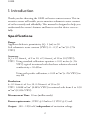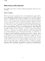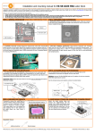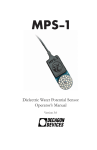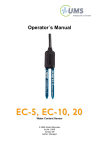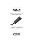
1
Operator´s Manual 10HS Water Content Sensor © UMS GmbH München Art.Nr. 10HS Version 04/2010 Author: Decagon ©2008 Decagon Devices, Inc. All rights reserved. Decagon Devices, Inc. 2365 NE Hopkins Court Pullman WA 99163 www.decagon.com Vertreten in Deutschland durch: UMS GmbH Gmunderstr. 37 D-81379 München Tel. +49 (0) 89-12 66 52-0 Fax: +49 (0) 89-12 66 52-20 [email protected] www.ums-muc.de Ansprechpartner: Thomas Keller Durchwahl: - 19 [email protected] 10HS Table of Contents 1. Introduction...................................................2 Specifications..................................................................................2 Contact Information.......................................................................3 Warranty Information.....................................................................4 2. About the 10HS..........................................5 3. Theory............................................................6 4. Installing the Sensors...............................7 Procedure........................................................................................7 5. Collecting Data..........................................9 Datalogger Requirements...............................................................9 Using the 10HS with Em50/Em50R and Em5b dataloggers..........9 3.5mm Stereo Plug Wiring............................................................10 Connecting to a non-Decagon Datalogger.....................................10 6. Calibration..................................................12 Dielectric calibration.....................................................................12 Mineral Soil Calibration................................................................12 7. Sample Programs.....................................14 1 10HS 1. Introduction Thank you for choosing the 10HS soil water content sensor. This innovative sensor will enable you to monitor volumetric water content of soil accurately and affordably. This manual is designed to help you understand the sensor’s features and how to use this device successfully. Specifications Range: Apparent dielectric permittivity (ea): 1 (air) to 50 Soil volumetric water content (VWC): 0 – 0.57 m3/m3 (0 -57% VWC) Accuracy: (ea): ± 0.5 from ea of 2 to 10, ±2.5 from ea of 10 to 50 (VWC): VWC: Using standard calibration equation: ± 0.03 m3/m3 (± 3% VWC) typical in mineral soils that have solution electrical conductivity < 10 dS/m Using soil specific calibration, ± 0.02 m3/m3 (± 2% VWC) in any soil Resolution: εa: 0.1 from ea of 1 to 30, 0.2 from ea of 30 to 50 VWC: 0.0008 m3/m3 (0.08% VWC) in mineral soils from 0 to 0.50 m3/m3 (0-50% VWC) Measurement Time: 10 ms (milliseconds) Power requirements: 3VDC @ 12mA to 15 VDC @ 15 mA Output: 300 – 1250 mV, independent of excitation voltage 2 10HS Operating Temperature: 0 – 50 °C Survival Temperature: -40 to 50 °C Connector types: 3.5 mm “stereo” plug or stripped and tinned lead wires Cable length: 5 m standard; custom cable length available upon request Datalogger Compatibility (non-exclusive): Decagon: Em50, Em50R, Em5b, ProCheck handheld reader. Campbell Scientific: CR10X, 21X, 23X, CR850, 1000, 3000, etc. Other: Any data acquisition system capable of switched 3 to15 V excitation and single ended voltage measurement at 12 bit or better resolution Contact Information E-mail: [email protected] Fax: (509)-332-5158 Telephone: (US and Canada only) 1-(800)-755-2751 or 509-332-2756 3 10HS Warranty Information The 10HS sensors have a 30-day satisfaction guarantee and a one year warranty. Seller’s Liability Seller warrants new equipment of its own manufacture against defective workmanship and materials for a period of one year from date of receipt of equipment (the results of ordinary wear and tear, neglect, misuse, accident and excessive deterioration due to corrosion from any cause are not considered to be a defect); but Seller’s liability for defective parts shall in no event exceed the furnishing of replacement parts f.o.b. the factory where originally manufactured. Material and equipment covered hereby which is not manufactured by the Seller shall be covered only by the warranty of its manufacturer. Seller shall not be liable to Buyer for loss, damage, or injuries to persons (including death), or to property or things of whatsoever kind (including, but not without limitation, loss of anticipated profits), occasioned by or arising out of the installation, operation, use, misuse, nonuse, repair, or replacement of said material and equipment, or out of the use of any method or process for which the same may be employed. The use of this equipment constitutes Buyer’s acceptance of the terms set forth in this warranty. There are no understandings, representations, or warranties of any kind, express, implied, statutory or otherwise, (including, but without limitation, the implied warranties of merchantability and fitness for a particular purpose), not expressly set forth herein. 4 10HS 2. About the 10HS The 10HS measures the dielectric constant of the soil in order to find its volumetric water content (VWC). Since the dielectric constant of water is much higher than that of air or soil minerals, the dielectric constant of the soil is a sensitive measure of volumetric water content. The 10HS has a low power requirement and very high resolution. This gives you the ability to make as many measurements as you want (i.e. hourly) over a long period of time with minimal battery usage. Background Info In 2005, the Decagon research team optimized a sensor oscillator frequency for very high accuracy soil moisture measurements. The first sensor to incorporate the new frequency was our EC-5 sensor. It quickly became the most popular soil moisture sensor we’ve designed. The new 10HS sensor uses the same 70MHz oscillator frequency as the EC-5 but has a larger soil volume and requires no special calibration when used with other systems. New features of the 10HS include: • Onboard voltage regulator allowing you to power the sensor with a wide range of excitation voltages (3-15 VDC) without changing the calibration • Large sensing (1100 cubic centimeters)allowing you to have a more representative measurement of soil VWC The 10HS sensor runs at the same oscillator frequency that has given the EC-5 exceptional performance in soils (Kizito et.al, 2008, Bogena et. al, 2007). We recommend the 10HS sensor for mineral soil applications where soil heterogeneity is a concern. However, we continue to recommend the smaller EC-5 sensor for soilless substrate applications or applications where VWC measurements on smaller scales (e.g. near surface measurements, laboratory column studies, greenhouse applications) are desired. 5 10HS 3. Theory The 10HS sensor measures the volumetric water content of the soil using a capacitance technique. By rapidly charging and discharging a positive and ground electrode (capacitor) in the soil, an electromagnetic field is generated whose charge time (t) is related to the capacitance (C) of the soil by V −Vf t = R C ln Vi − V f (1) where R is the series resistance, V is voltage at time t, Vi is the starting voltage and Vf is the applied or supply voltage. Further, for a capacitor with a geometrical factor of F, the capacitance is related to the dielectric permittivity (e) of the medium between the capacitor electrodes by C = e o eF (2) where eo is the permittivity of free space. Thus, the e of the soil can be determined by measuring the change time (t) of a sensor buried in the soil. Consequently, as water has a dielectric permittivity that is much greater than soil minerals or air, the charge time t in the soil of Eq. (1) can be correlated with soil volumetric water content. 6 10HS 4. Installing the Sensors When selecting a site for installation, it is important to remember that the soil adjacent to the sensor surface has the strongest influence on the sensor reading and that the sensor measures the volumetric water content of the soil. Therefore any air gaps or excessive soil compaction around the sensor and in between the sensor prongs can profoundly influence the readings. Also, do not install the sensors adjacent to large metal objects such as metal poles or stakes. This can attenuate the sensor’s electromagnetic field and adversely affect readings. In addition, the 10HS sensor should not be installed within 5 cm of the soil surface, or the sensing volume of the electromagnetic field can extend out of the soil and reduce accuracy. Because the 10HS has gaps between its prongs, it is also important to consider the particle size of the medium you are inserting the sensor into. It is possible to get sticks, bark, roots or other material stuck between the sensor prongs, which will adversely affect readings. Finally, be careful when inserting the sensors into dense soil, as the prongs can break if excessive sideways force is used when pushing them in. Procedure When installing the 10HS it is imperative to maximize contact between the sensor and soil. For most accurate results, the sensor should be inserted into undisturbed soil. There are two basic methods to accomplish a high quality installation. Method 1. Horizontal Installation: Excavate a hole or trench a few centimeters deeper than the depth at which the sensor is to be installed. At the installation depth, shave off some soil from the vertical soil face exposing undisturbed soil. Insert the sensor into the undisturbed soil face until the entire sensing portion of the 10HS is inserted. The tip of each prong has been sharpened to make it easier to push the sensor in – be careful with the sharp tips! Backfill the trench taking care to pack the soil back to natural bulk density around the black plastic portion of the 10HS. 7 10HS Method 2. Vertical Installation: Auger a 4 inch hole to the depth at which the sensor is to be installed. Insert the sensor into the undisturbed soil at the bottom of the auger hole using your hand or any other implement that will guide the sensor into the soil at the bottom of the hole. Many people have used a simple piece of PVC pipe with a notch cut in the end for the sensor to sit in, with the sensor cable routed inside the pipe. After inserting the sensor, remove the installation device and backfill the hole taking care to pack the soil back to natural bulk density while not damaging the black plastic portion of the sensor or the sensor cable in the process. With either of these methods, the sensor may still be difficult to insert into extremely compact or dry soil. Never pound the sensor into the soil! If you have difficulty inserting the sensor, you may need to wet the soil. This will obviously result in inaccurate VWC measurements until the water added during installation redistributes into the surrounding soil. Orientation The sensor can be oriented in any direction. However, orienting the flat side perpendicular to the surface of the soil will minimize effects on downward water movement. Keep in mind that the sensor measures the average VWC along its length, so a vertical installation will integrate VWC over a 10 cm depth while a horizontal orientation will measure VWC at a more discrete depth. Removing the Sensor When removing the sensor from the soil, do not pull it out of the soil by the cable! Doing so may break internal connections and make the sensor unusable. 8 10HS 5. Collecting Data Data logger Requirements The 10HS is designed to work most efficiently with Decagon’s Em50 Em50R, or EM5b data loggers or our ProCheck handheld readout. They can, however, be adapted for use with other data loggers, such as those from Campbell Scientific, Inc., for example. The 10HS requires an excitation voltage in the range of 3 to 15V. It produces an output voltage that is related to the volumetric water content of the soil in which it is buried, and ranges between approximately 0.3 to 1.25V. The output of the 10HS is independent of the excitation voltage between 3 and 15V. Any datalogger which can produce a 3 to 15V excitation with approximately 10 millisecond duration and read a voltlevel signal with 12-bit or better resolution should be compatible with the 10HS. The current requirement for the 10HS is less than 15mA. Note: The 10HS is intended only for use with dataloggers and readout devices which can provide short excitation pulses, leaving the sensor turned off most of the time. Continuous excitation not only wastes battery power, but may, under certain circumstances, cause the sensor to exceed government specified limits on electromagnetic emissions. Using the 10HS with Em50/Em50R and Em5b data loggers The 10HS is designed for very easy integration into the Em50, EM50R and Em5b based data logging systems. Simply plug the stereo plug into one of the five ports on the Em50/Em50R or Em5b, use ECH2O Utility, ECH2O Utility Mobile or DataTrac software to configure that port for a 10HS (see respective manuals) and set a measurement interval for the logger. For more detailed instructions on configuring the data logger, consult your Em50/Em50R or Em5b user manual. 9 10HS 3.5mm Stereo Plug Wiring 10HS sensors used with Decagon loggers come with a 3.5mm “stereo plug” connector. The stereo plug allows for rapid connection directly to Decagon’s Em50, Em50R, and Em5b dataloggers and to the hand-held ProCheck readers. Below is a diagram showing the wiring configuration for this connector. Analog out Ground Excitation Extending sensor cables Decagon supplies 10-foot (3m) and 50-foot (15.25m) extension cables for use with the stereo plug type 10HS sensors. You can safely connect up to four of the 50-foot cables without signal attenuation. For field applications, it is critical to seal the connections from the elements to maintain a good connection and to prevent corrosion. It is imperative that these connections are checked before the sensor is buried. Please see the Decagon web-site (www.decagon.com) for an application note detailing some preferred methods for waterproofing these connections. Connecting to a non-Decagon Data logger 10HS sensors for use with non-Decagon data loggers come pre-configured with stripped and tinned lead wires at the customer’s request. Analog out (Red) Ground (Bare) Sensor cable Excitation (White) 10 Extending sensor cables with UMS M12 cables CC-4/1.5, CC-4/5, CC-4/10, CC-4/20 "Supply +" equates Excitation, "Supply -" equates Ground (internal connected with "Signal -") "Signal +" equates Analog out © UMS GmbH München Art.Nr. 10HS Version 09/2008 Author: Decagon 10HS 10HS sensors with the stripped and tinned cable option can be made with custom cable lengths (up to 250 ft) on a per-foot fee basis. This option gets around the need for splicing wire (a possible failure point). Connect the wires to the data logger as shown, with the supply wire (white) connected to the excitation, the analog out wire (red) to an analog input, and the bare ground wire to ground as seen below. Supply Analog out H Switched 3-15V DC Analog Ground L G In Datalogger Note: The acceptable range of excitation voltages is from 3-15VDC. If you wish to read the 10HS with Campbell Scientific data loggers, you will need to power the sensors off of the switched 12V port rather than the excitation port. If your 10HS is equipped with the standard 3.5mm plug, and you wish to connect it to a non-Decagon datalogger, you have two options. First, you can clip off the plug on the sensor cable, strip and tin the wires, and wire it directly into the datalogger. This has the advantage of creating a direct connection with no chance of the sensor becoming un-plugged; however, it then cannot be easily used in the future with a Decagon readout unit or datalogger. The other option is to obtain an adapter cable from Decagon. The 3-wire sensor adapter cable has a connector for the sensor jack on one end, and three wires on the other end for connection to a datalogger (this type of wire is often referred to as a “pigtail adapter”). Both the stripped and tinned adapter cable wires have the same termination as seen above; the white wire is excitation, red is output, and the bare wire is ground. 11 10HS 6. Calibration Dielectric calibration The 10HS comes pre-calibrated to measure the dielectric permittivity of the soil with the accuracy stated in the specification section above. With Decagon’s Em50, Em50R, Em5B, and ProCheck readers, the following standard calibration function can be applied. ea = 7.449 X 10⁻¹¹ * raw counts4 - 1.969 X 10 -7 * raw counts3 + 1.890X 10⁻⁴ * raw counts2 - 6.691 X 10⁻² * raw counts + 7.457 With non-Decagon data acquisition equipment, the following calibration can be applied. Note that this calibration function is valid for any sensor excitation between 3 and 15 V DC. ea = 2.589 X 10⁻¹⁰ * mV4 – 5.010 X 10 -7 * mV3 + 3.523 X 10⁻⁴ * mV2 – 9.135 X 10⁻² * mV + 7.457 Mineral Soil Calibration For convenience, Decagon has also developed a standard calibration equation for mineral soils to be used with the 10HS. With this standard calibration equation and careful sensor installation, accuracy of better than ±3% VWC (0.03 m3/m3) is possible with most mineral soils. In these soils, it is generally not necessary to calibrate the 10HS for your particular soil type, and the standard mineral calibration below can be used. Em50, Em50R, Em5B, and ProCheck: -7 2 3 -3,95*10 counts – 1.47-6 X 10⁻⁴ * raw counts VWC (m3/m3) = 3.13 VWC(m³/m³)= 1,17X *1010-9* raw * raw x raw² – 5.82 X 10⁻² +4,90*10-3* *raw - 1,92 (Doug Cobos 03/2010) 12 10HS With non-Decagon data acquisition equipment, the following calibration can be applied. Note that this calibration function is valid for any sensor excitation between 3 and 15 V DC. -7 2 mV 2.01 X-610-4 * mV – 5.82 X VWC (m3/m3) = 5.84 X 10 -9 * *mV 3 -– VWC(m³/m³)= 2,97*10 7,37*10 * mV2 -2 10 + 6,69*10-3 * mV - 1,92 (Doug Cobos 03/2010) Due to the complexity of soils, the accuracy of the VWC measurement can be poor despite an accurate measurement of dielectric permittivity. Some examples of this are highly compacted soils, very low bulk density soils, soils with abnormally high organic matter content, and soils with high-dielectric mineral composition (e.g. TiO2 sands). Additionally, the accuracy of the 10HS may suffer in soils with very high electrical conductivity (> 10 dS/m solution EC). In these soils, it may be necessary to calibrate the 10HS to your specific soil type. With a soil-specific calibration, the accuracy of the VWC measurement will be improved to 1-2% in any soil or other porous medium. If you are interested in a soil-specific calibration for your 10HS, there are two options available. You can create your own sensor calibration by following the directions in our application note titled Calibrating ECH2O soil moisture probes from the Decagon website (www.decagon.com) and following the step-by-step instructions for calibrating your soil moisture sensors. Since some users do not have the time or equipment to conduct their own calibration, Decagon now offers a service providing soil-specific calibrations to our customers. This calibration service also applies to non-soil materials, such as compost, potting materials, etc. Contact Decagon for more information on this service ([email protected]). 13 10HS 7. Sample Programs The following programs are examples that can be used with dataloggers from Campbell Scientific. The first program is for a CR1000 data logger, but can be easily adapted for other “CRBasic” type loggers. The second program is for a CR10X data logger, but can be easily adapted to other “Edlog” type loggers. Note that the 10HS needs 3-15 V DC excitation, and therefore cannot be excited with the 2.5 V excitation port of many Campbell Scientific data loggers. We recommend that the switched 12V or CAO port be used to excite the 10HS. CR Basic type datalogger ‘CR1000 Series Datalogger ‘program to read one Decagon 10HS sensor ‘ ‘wiring: ‘white - SW-12 ‘red - SE CH1 ‘bare - gnd Public tenHSmV, VWC DataTable (Test,1,-1) DataInterval (0,60,Min,10) Average (1,VWC,FP2,False) EndTable BeginProg Scan (30,Sec,0,0) SW12 (1) Delay (0,10,mSec) VoltSe (tenHSmV,1,mV2500,1,1,0,_60Hz,1.0,0) SW12 (0) VWC = 5.84e-7 * tenHSmV^2 -2.01e-4 * tenHSmV - 5.82e-2 ‘mineral soil calibration 14 10HS CallTable Test NextScan EndProg Edlog type data logger ;{CR10X} ;program to read 10HS sensor with CR10X ;wiring: ;Jumper from C1 to SW 12V CTRL - C1 is used to turn on the ;switched 12V port ;10HS white - excitation - SW 12V ;10HS red - Vout - SE CH1 ;10HS bare - gnd - G or AG *Table 1 Program 01: 30 Execution Interval (seconds) ;set C1 high to pull SW 12 port high 1: Do (P86) 1: 41 Set Port 1 High ;delay program 10 ms and measure SE channel 1 2: Excite-Delay (SE) (P4) 1: 1 Reps 2: 5 2500 mV Slow Range 3: 1 SE Channel 4: 1 Excite all reps w/Exchan 1 5: 1 Delay (0.01 sec units) 6: 0000 mV Excitation 7: 1 Loc [ ten_HS_V ] 8: .001 Multiplier 9: 0.0 Offset ;turn off excitation 15 10HS 3: Do (P86) 1: 51 Set Port 1 Low ;apply calibration 4: Polynomial (P55) 1: 1 Reps 2: 1 X Loc [ ten_HS_V ] 3: 2 F(X) Loc [ VWC ] 4: -0.0582 C0 5: -.201 C1 6: .584 C2 7: 0.0 C3 8: 0.0 C4 9: 0.0 C5 5: If time is (P92) 1: 0000 Minutes (Seconds --) into a 2: 60 Interval (same units as above) 3: 10 Set Output Flag High (Flag 0) 6: Real Time (P77) 1: 1110 Year,Day,Hour/Minute (midnight = 0000) 7: Average (P71) 1: 1 Reps 2: 2 Loc [ VWC ] *Table 2 Program 02: 0.0000 Execution Interval (seconds) *Table 3 Subroutines End Program 16 10HS 17 10HS Index A Accuracy 2 alternate connection methods 11 B Background 5 C Cable length 3 calibration 13 calibration service 13 Campbell Scientific 9 capacitance technique 6 Compatibility 3 Connector types 3 Contact 3 D datalogger connections 11 dielectric permittivity 6 duration 9 E ECH2O Utility 9 Edlog 14 electromagnetic field 7 extension cables 10 F Frequency 5 I Installation 7 Horizontal 7 Vertical 8 Introduction 2 18 10HS L Liability 4 M Measurement Time 2 Mineral soil calibration 12 O Operating Temperature 3 Orientation 8 Output 2 P particle size 7 Power requirements 2 programs 14 R Range 2 removing the sensor 8 Resolution 2 S Sample Programs 14 Specifications 2 stereo plug 10 Survival Temperature 3 T Theory 6 W Warranty 4 wiring configuration 10 19