1
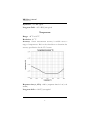
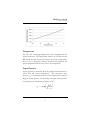
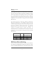
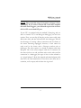
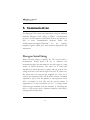
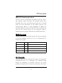
VP-3 Vapor Pressure, Temperature & Relative Humidity Sensor Operator’s Manual Version 0 Decagon Devices, Inc. 2365 NE Hopkins Court Pullman WA 99163 USA [email protected] tel: 1-509-332-5600 fax:(509) 332-5158 www.decagon.com VP-3 User’s Manual Table of Contents 1. Introduction . . . . . . . . . . . . . . . . 1 Customer Support . . . . . . . . . . . . . . . . . . . . . . .2 Specifications . . . . . . . . . . . . . . . . . . . . . . . . . . . 3 Warranty. . . . . . . . . . . . . . . . . . . . . . . . . . . . . . . 6 Seller’s Liability . . . . . . . . . . . . . . . . . . . . . . . . . 6 2. Measurements . . . . . . . . . . . . 8 3. RH Sensor. . . . . . . . . . . . . . . . 11 RH Sensor Stability . . . . . . . . . . . . . . . . . . . . . 11 RH Sensor Recalibration . . . . . . . . . . . . . . . . . 13 4. Connecting Sensors . . . . . . . . 14 Connecting to an Em50 Series logger . . . . . . .14 Connecting to a Non-Decagon Logger . . . . . 16 5. Communication . . . . . . . . . . 18 Decagon Serial String . . . . . . . . . . . . . . . . . . . 18 SDI-12 Communication . . . . . . . . . . . . . . . . . 19 SDI-12 Commands . . . . . . . . . . . . . . . . . . 19 SDI-12 Sensor Bus . . . . . . . . . . . . . . . . . . 19 SDI-12 Address. . . . . . . . . . . . . . . . . . . . . 20 Power . . . . . . . . . . . . . . . . . . . . . . . . . . . . 21 Reading . . . . . . . . . . . . . . . . . . . . . . . . . . . 21 VP-3 User’s Manual 6. Installation . . . . . . . . . . . . . 22 Installation in a Radiation Shield. . . . . . . . . . . 22 7. Troubleshooting . . . . . . . . . . 24 8. References . . . . . . . . . . . . . . . 25 Declaration of Conformity. . . . . 26 Index . . . . . . . . . . . . . . . . . . . . . . 28 VP-3 User’s Manual 1. Introduction 1. Introduction About the VP-3 Thank you for choosing Decagon’s VP-3 for measuring vapor pressure, temperature and relative humidity (RH). This manual is designed to help you understand the sensor’s features and how to use this device successfully. The Decagon VP-3 sensor is an accurate tool for monitoring vapor pressure, temperature and relative humidity. The VP-3 utilizes a single sensor chip that measures both temperature and RH. Each RH/T sensor chip is individually calibrated with temperature and RH calibrations stored on board and applied before data are output, ensuring best possible accuracy. A micro-processor within the VP-3 calculates vapor pressure from the RH and temperature measurements and outputs all three parameters using an RS232 (TTL) string and the common SDI-12 communication protocol. The VP-3 sensor is packaged in a rugged Delrin housing with the sensor electronics potted in marine grade polyurethane encapsulant. The RH/T sensor chip is protected by a hydrophobic porous Teflon filter that is water and dust proof, but has an extremely high vapor conductance allowing fast sensor equilibration with the surrounding atmosphere. An additional stainless steel screen protects the Teflon filter and RH/T sensor from impact and abrasion. The resulting ultra-rugged design allows the VP-3 to withstand permanent exposure to hostile conditions, making it ideal for a wide range of 1 VP-3 User’s Manual 1. Introduction applications including standard meteorological/weather monitoring, evapotranspiration measurement, micro-environment monitoring, greenhouse monitoring and control, concrete moisture monitoring, and building humidity monitoring for mold prevention/ remediation. Customer Support If you ever need assistance with your VP-3, or if you just have questions or feedback, there are several ways to contact us. Customer service representatives are available to speak with you Monday through Friday, between 7am and 5pm Pacific time. NOTE: If you purchased your VP-3 through a distributor, please contact them for assistance. E-mail: [email protected] or [email protected] Phone: 1-509-332-5600 Fax: 1-509-332-5158 If contacting us by email or fax, please include as part of your message the sensor’s name, your name, address, phone, and fax number. 2 VP-3 User’s Manual 1. Introduction Specifications Relative Humidity Range: 0 to 100 % RH Resolution: 0.1% RH Accuracy: Sensor measurement accuracy is variable across a range of RH. Refer to the chart below to determine the accuracy specification for the VP-3 sensor: Response time (τ, 63%): <40 s (response time in 1 m/s air stream) 3 VP-3 User’s Manual 1. Introduction Hysteresis: < 1% RH typical Long term Drift: < 0.5% RH/year typical Temperature Range: -40 oC to 80 oC Resolution: 0.1 oC Accuracy: Sensor measurement accuracy is variable across a range of temperatures. Refer to the chart below to determine the accuracy specification for the VP-3 sensor: Response time (τ, 63%): <400 s (response time in 1 m/s air stream) Long term drift: < 0.04 °C/year typical 4 VP-3 User’s Manual 1. Introduction Vapor Pressure Range: 0 to 47 kPa Resolution: 0.01 kPa Accuracy: Sensor measurement accuracy is variable across a range of temperatures and RH. Refer to the chart below to determine the accuracy specification for the VP-3 sensor: General Dimensions: 1.96 cm (dia) x 5.4 cm (h) Power requirements: 3.6 - 15 VDC, 0.03mA quiescent, 4mA during 300ms measurement Output: RS232 (TTL) or SDI-12 5 VP-3 User’s Manual 1. Introduction Operating Temperature: -40 to 80 °C Connector types: 3.5 mm (stereo) plug or stripped & tinned lead wires (Pigtail) Cable Length: 5m standard; custom cable length available upon request Datalogger Compatibility (not exclusive): Decagon: Em50, Em50R, Em50G (Firmware 2.11+) Campbell Scientific: Any logger with serial I/O (CR10X, CR850, 1000, 3000, etc.) Handheld Reader Compatibility ProCheck (rev 1.5C+) Software Compatibility ECH2O Utility (rev 1.65+), DataTrac (rev 3.6+) Warranty All Decagon products have a 30-day satisfaction guarantee and a one-year warranty on parts. Seller’s Liability Seller warrants new equipment of its own manufacture against defective workmanship and materials for a period of one year from date of receipt of equipment (the results of ordinary wear and tear, neglect, misuse, accident and excessive deterioration due to corrosion from any cause are not to be considered a defect); 6 VP-3 User’s Manual 1. Introduction but Seller’s liability for defective parts shall in no event exceed the furnishing of replacement parts F.O.B. the factory where originally manufactured. Material and equipment covered hereby which is not manufactured by Seller shall be covered only by the warranty of its manufacturer. Seller shall not be liable to Buyer for loss, damage or injuries to persons (including death), or to property or things of whatsoever kind (including, but not without limitation, loss of anticipated profits), occasioned by or arising out of the installation, operation, use, misuse, nonuse, repair, or replacement of said material and equipment, or out of the use of any method or process for which the same may be employed. The use of this equipment constitutes Buyer’s acceptance of the terms set forth in this warranty. There are no understandings, representations, or warranties of any kind, express, implied, statutory or otherwise (including, but without limitation, the implied warranties of merchantability and fitness for a particular purpose), not expressly set forth herein. 7 VP-3 User’s Manual 2. Measurements 2. Measurements Relative Humidity The VP-3 utilizes a capacitance type RH sensor to measure the relative humidity of the surrounding air. Relative humidity is measured at the same location as the temperature sensor. For this to be an accurate representation of the atmospheric humidity, it is critical that the humidity sensor be at air temperature. For most measurement scenarios, the VP-3 should be housed in a radiation shield with adequate air flow to allow the sensor to come into equilibrium with air temperature. This is not as critical for non-greenhouse, indoor monitoring applications where radiation loading is small. The VP-3 sensor provides a RH measurement that is referenced to saturation vapor pressure over liquid water, even at temperatures below freezing where ice is likely to be present instead of super-cooled water. Although this is the standard way to define RH (WMO, 2008), it has the disadvantage of providing incorrect RH values below freezing when referenced to ice. The figure below shows the maximum RH that will be measured by the VP-3 sensor (at saturation, 100% RH) at temperatures below zero. RH values below saturation can be corrected using the correction shown in the figure for a given temperature. 8 VP-3 User’s Manual 2. Measurements Temperature The VP-3 has a band gap temperature sensor integrated into the sensor electronics. The temperature sensor is co-located with the RH sensor and will accurately measure the sensor temperature. If the VP-3 is adequately radiation shielded and aspirated, the sensor temperature will be very close to air temperature. Vapor Pressure Vapor pressure is calculated from the primary measurements of sensor RH and sensor temperature. The saturation vapor pressure (es) is calculated from the sensor temperature using the Magnus-Tetens equation for calculating saturation vapor pressure over liquid water formulated by Murray (1967) 1b T 1 e s = a exp --------------- T + c a 9 VP-3 User’s Manual 2. Measurements with coefficients described by Buck (1981): a = 0.611 kPa, b = 17.502, c = 240.97 °C, and T is temperature in °C. Vapor pressure is simply the product of saturation vapor pressure and RH, with RH expressed as a unitless ratio ranging from 0 to 1. Vapor pressure = es * RH Unlike relative humidity, vapor pressure does not depend on temperature, and is relatively conservative over small spatial scales. This means that the vapor pressure of the atmosphere near the VP-3 is the same as the vapor pressure at the VP-3 sensor, even if the VP-3 isn’t at the same temperature as the atmosphere. Additionally, it is the vapor pressure of the atmosphere (not RH) that controls the rate of vapor phase water transport (e.g. evaporation, transpiration, and re-distribution of water vapor). As discussed above, RH measurements below a temperature of 0 °C will have error introduced due to the use of liquid water as the reference. However, because the Buck (1981) formulation for liquid water is used to calculate vapor pressure over the full temperature range, the vapor pressure values output by the VP-3 will be correct over the full temperature range. 10 VP-3 User’s Manual 3. RH Sensor 3. RH Sensor RH Sensor Stability Each VP-3 sensor is verified as accurate before leaving our facility. However, all capacitance RH sensors will drift over long periods of exposure to environmental conditions. The VP-3 RH sensor typically drifts less than 0.5% RH per year. We recommend that VP-3 sensors be re-calibrated every 1 to 2 years under normal use conditions to ensure best possible accuracy. To have your VP-3 fully calibrated or re-calibrate contact [email protected] and ask about our calibration service. The polymer RH sensing element in the VP-3 can also be “poisoned” by exposure to volatile organic compounds, solvents, and other chemicals. The effects of exposure to these chemicals can range from subtle loss of accuracy to catastrophic failure. If you suspect that your VP-3 has suffered chemical exposure or notice questionable RH measurements, you can check the sensor accuracy using known RH conditions. A convenient method for generating known RH conditions is through the use of salt solutions. For an initial check, we recommend preparing a saturated NaCl solution, which has an equilibrium RH of 0.75 (75%). To prepare the salt solution, start with lab grade NaCl and mix in enough water that there is a thin 11 VP-3 User’s Manual 3. RH Sensor layer of liquid water present over a thick slurry of NaCl crystals. The VP-3 sensor can either be sealed into a chamber or bell jar with the salt solution or the opening of the VP-3 can be sealed into a small chamber that contains the salt solution. Whatever method is used, it is critical that the VP-3 sensor be at the same temperature as the salt solution or large errors in the measured RH will occur. Salt solutions prepared at a wide range of RH are available from Decagon (see chart below). It is possible to prepare your own solutions using the mixing ratios shown below, but great care and precision are required to obtain accurate results. It is especially important that the salt used be pure and dry. Decagon’s salt solutions are specified accurate to within ±0.3% RH. As mentioned above, it is critical that the VP-3 sensor be at the same temperature as the salt solution or large errors in the measured RH will occur. EquilibriumRH (%saturation) 25% 50% 76% 92% Salt LiCl LiCl NaCl NaCl Molality(m) (molsalt/kgwater) 13.41m 8.57m 6.00m 2.33m RH Sensor Reconditioning If a VP-3 sensor has been exposed to solvents or other chemicals, the following reconditioning procedure may bring the sensor back to the original calibration state. First, bake the sensor in dry 12 VP-3 User’s Manual 3. RH Sensor heat at 100 – 105 °C for 10 hours. Then re-hydrate the sensors at 20 – 30°C under ~75% RH for 12 hours. A 75% RH environment can be conveniently established by sealing the sensor in a headspace over saturated NaCl prepared as described above. RH Sensor Recalibration Decagon offers a service to recalibrate VP-3 sensors (contact Decagon Support at [email protected] for more information). Sensors are calibrated at 25%, 50%, and 76% RH. The calibration values are stored onboard the VP-3 sensor, allowing the data to be corrected before being output, thus eliminating the need for calibration during post-processing. We recommend that VP-3 sensors be re-calibrated every 1 to 2 years under normal use conditions to ensure best possible accuracy. For safety-critical or especially high accuracy applications, more frequent recalibration is recommended. Additionally, if sensors have been poisoned by chemical exposure and reconditioning fails to restore accurate measurements, the sensors should be sent back to Decagon for evaluation and possible recalibration. 13 VP-3 User’s Manual 4. Connecting Sensors 4. Connecting Sensors The VP-3 sensor was designed to work most efficiently with Decagon’s Em50, Em50R, Em50G dataloggers, or the ProCheck handheld reader. The standard sensor (with 3.5 mm stereo connector) quickly connects to and is easily configured within a Decagon logger or ProCheck. The VP-3 sensor incorporates several features that also make it an excellent sensor for use with third party loggers. The sensor may be purchased with stripped and tinned wires (pigtail) for terminal connections. Visit our website at www.decagon.com/ support/literature to get extensive directions on how to integrate the VP-3 sensor into third party loggers. The VP-3 sensor comes standard with a 5 meter cable. Sensors may be purchased with custom cable lengths for an additional fee (on a per-foot fee basis). Decagon has tested its digital sensor successfully up to 1000 meters (3200 ft). This option eliminates the need for splicing the cable (a possible failure point). Connecting to an Em50 Series Logger The VP-3 has been designed to work specifically with the Em50 data logger. Simply plug the 3.5mm “stereo plug” connector directly into one of the five sensor ports. 14 VP-3 User’s Manual 4. Connecting Sensors Ground Data Power Figure 1: 3.5mm Stereo Plug Wiring The next step is to configure your logger port for the VP-3 and set the measurement interval, this may be done using either ECH2O Utility or DataTrac 3 (see respective manuals). Please check your software version to ensure it will support the VP-3. To update your software to the latest version, please visit Decagon’s free software download site: www.decagon.com/ support/downloads. The following firmware and software support the VP-3 sensor: Em50, Em50R, Em50G Firmware version 2.11 or greater ProCheck Firmware version 1.5C or greater ECH2O Utility 1.65 or greater ECH2O DataTrac 3.6 or greater To download data from the logger to your computer, you will need to use the ECH2O Utility, DataTrac 3 or a terminal program on your computer. 15 VP-3 User’s Manual 4. Connecting Sensors Connecting to a Non-Decagon Logger The VP-3 sensor may be purchased for use with non-Decagon data loggers. These sensors typically come pre-configured with stripped and tinned (pigtail) lead wires for use with screw terminals. Refer to your distinct logger manual for details on wiring. Our integrator’s guide gives detailed instructions on connecting the VP-3 sensor to non-Decagon loggers. Please visit www.decagon.com/support/literature to reference the complete integrator’s guide. Pigtail End Wiring Ground (Bare) Data (Red) Power (White) Connect the wires to the data logger as shown, with the supply wire (white) connected to the excitation, the digital out wire (red) to a digital input, the bare ground wire to ground as illustrated below. Supply Digital out 3.6-15V DC Ground Digital In Datalogger 16 G VP-3 User’s Manual 4. Connecting Sensors NOTE: The acceptable range of excitation voltages is from 3.6-15 VDC. If you wish to read the VP-3 with the Campbell Scientific Data Loggers, you will need to power the sensors off of a 12V or switched 12V port. If your VP-3 is equipped with the standard 3.5mm plug, and you wish to connect it to a non-Decagon datalogger, you have two options. First, you can clip off the plug on the sensor cable, strip and tin the wires, and wire it directly into the datalogger. This has the advantage of creating a direct connection with no chance of the sensor becoming unplugged; however, it then cannot be easily used in the future with a Decagon readout unit or datalogger. The other option is to obtain an adapter cable from Decagon. The 3-wire sensor adapter cable has a connector for the sensor jack on one end, and three wires on the other end for connection to a datalogger (this type of wire is often referred to as a “pigtail adapter”). Both the stripped and tinned adapter cable wires have the same termination as seen above; the white wire is excitation, red is output, and the bare wire is ground. 17 VP-3 User’s Manual 5. Communication 5. Communication The Decagon VP-3 sensor can communicate using two different methods, Decagon serial string or SDI-12 communication protocol. In this chapter we will briefly discuss the specifics of each of these communication methods. Please visit www.decagon.com/support/literature for the complete integrator's guide, which gives more detailed explanations and instructions. Decagon Serial String When excitation voltage is applied, the VP-3 sensor makes a measurement. Within about 140 ms of excitation two measurement values are transmitted to the data logger as a serial stream of ASCII characters. The serial out is 1200 baud asynchronous with 8 data bits, no parity, and one stop bit. The voltage levels are 0-3.6V and the logic levels are TTL (active low). The power must be removed and reapplied for a new set of values to be transmitted. The ASCII stream contains 2 numbers separated by spaces. The first number is vapor pressure in kPa with a resolution of 0.01 kPa and the second number is temperature in °C with a resolution of 0.1 °C. A carriage return follows the two numbers, then the character 'p', indicating that this is a CTD sensor, then a checksum character, and finally a carriage return and line feed. 18 VP-3 User’s Manual 5. Communication SDI-12 Communication The VP-3 can also communicate using SDI-12 protocol, a threewire interface where all sensors are powered (white wire), grounded (bare wire), and communicate (red wire) on shared nodes (for more information on the SDI-12 protocol, visit www.sdi-12.org). Below is a brief description of SDI-12 for communication. If you plan on using SDI-12 for communication with the VP-3 Sensor, please see our integrator's guide at www.decagon.com/support/literature for detailed instructions. SDI-12 Commands Following are SDI-12 commands that the VP-3 Sensor responds to. The sensor address is shown as 'a'. If a '?' is substituted for 'a' all addresses respond. Send Identification aI! a13DECAGON VP-3 350<CR><LF> Change Address aAb! b<CR><LF> (b is new address) Address Query ?! a<CR><LF> Start Measurement aM! a0013<CR><LF> Send Data aD0! a+1.17+21.5+0.456<CR><LF> (3 values) SDI-12 Sensor Bus Up to 62 sensors can be connected to the same 12 V supply and communication port on a datalogger. This simplifies wiring because no multiplexer is necessary. However, one sensor problem can bring down the entire array (through a short circuit 19 VP-3 User’s Manual 5. Communication or incorrect address settings). If you use an SDI-12 sensor bus we recommend that you make an independent junction box with wire harnesses where all sensor wires attach to lugs so sensors can be disconnected individually if a problem arises. A single three-wire cable can be run from the junction box to the datalogger. SDI-12 Address The SDI-12 protocol requires that all sensors have a unique address. VP-3 sensors come from the factory with an SDI-12 address of 0. To add more than one SDI-12 sensor to a system, the sensor address must be changed. Address options include {0...9, A...Z, a...z}. The best and easiest way to change an address is to use Decagon's ProCheck (if the option is not available on your ProCheck, please upgrade to the latest version of firmware). SDI-12 addressing can be accessed in the "CONFIG" menu by selecting "SDI-12 Address." Addresses may then be changed by simply pressing the up or down arrows until you see the desired address and pushing "Enter." The SDI-12 communication protocol is supported by Campbell Scientific dataloggers like the CR10X, CR200, CR1000, CR3000, etc. Direct SDI-12 communication is supported in the "Terminal Emulator" mode under the "Tools" menu on the "Connect" screen. Detailed information on setting the address using CSI dataloggers can be found on our website at http:// www.decagon.com/support/downloads. 20 VP-3 User’s Manual 5. Communication Power The VP-3 is an extremely low power sensor. When continuously powered, but not making a measurement or communicating, it uses 30A. When using the sensor as part of an SDI-12 bus, it is recommended that the sensors be excited continuously to avoid issues with initial sensor startup interfering with the SDI-12 communications. Reading When reading the VP-3 in SDI-12 mode, the first number output by the sensor is vapor pressure in kPa, the second number is temperature in Celsius, and the third number relative humidity in a unitless ratio from 0 to 1 (0 – 100%). 21 VP-3 User’s Manual 6. Installation 6. Installation Installation in a Radiation Shield Relative humidity is measured at the temperature of the humidity sensor. For this to be an accurate representation of the atmospheric humidity, it is critical that the humidity sensor be at air temperature. For most outdoor and greenhouse measurement scenarios, the VP-3 should be housed in a radiation shield with adequate air flow to allow the sensor to come into equilibrium with air temperature. In general, the higher the wind speed, the more accurate the temperature and relative humidity measurements will be. A radiation shield is not critical for nongreenhouse, indoor monitoring applications where radiation loading is small. Decagon’s radiation shield comes with a mounting bracket and seven discs that prevent direct sunlight from coming into coming contact with the sensor. This isolation from solar radiation prevents false readings of elevated temperatures, allowing for accurate measurement of ambient air temperature. To install the sensor in the radiation shield follow the directions below: 1. Gently pry the white cap from the bottom center hole of the radiation shield. 2. Slide the white cap onto the cable of the sensor. 22 VP-3 User’s Manual 6. Installation 3. Insert the sensor into the bottom of the shield and snap the cap back into place. 4. The unit can then be mounted on the desired surface for your study. NOTE: Be sure to fasten the sensor cord to your mounting post to help support the weight of the cable in order to prevent it from being pulled out. 23 VP-3 User’s Manual 7. Troubleshooting 7. Troubleshooting If you encounter problems with the VP-3 sensor, they most likely will manifest themselves in the form of no reading from communication problems or catastrophic sensor failure, or highly inaccurate measurements due to sensor poisoning by volatile chemicals. Before contacting Decagon about the sensor, do the following: Data Logger 1. Check to make sure the connections to the data logger are both correct and secure. 2. Ensure that your data logger's batteries are not dead or weakened. 3. Check the configuration of your data logger in ECH2O Utility or ECH2O DataTrac to make sure you have selected VP-3. Sensors 1. Check sensor cables for nicks or cuts that could cause a malfunction. 2. Check your screen and filter to make sure that they are not contaminated or blocked. Airflow must not be restricted through the filter. 3. In the case of inaccurate readings, consider evaluating sensor accuracy and/or reconditioning the sensor as described in the RH Sensor section. 24 VP-3 User’s Manual 8. References 8. References Buck, A.L., 1981. New equations for computing vapor pressure and enhancement factor. Journal of Applied Meteorology, 20: 1527-1532 Goff, J.A. and S. Gratch, 1946. Low-pressure properties of water from -160° to 212°F. Transactions of the American society of heating and ventilating engineers, 51: 125-164 Murray, F.W., 1967. On the computation of saturation vapor pressure. Journal of Applied Meteorology, 6: 203-204. WMO, 2008. Guide to meteorological instruments and methods of observation. World Meteorological Organization No. 8, 7th edition, Geneva, Switzerland. 25 VP-3 User’s Manual Declaration of Conformity Declaration of Conformity Application of Council Directive: 89/336/EEC Standards to which Conformity is Declared: EN61326: 1998 EN55022: 1998 Manufacturer’s Name: Type of Equipment: Decagon Devices, Inc. 2365 NE Hopkins Court Pullman, WA 99163 USA Temperature, Relative Humidity and Vapor Pressure Sensor Model Number: VP-3 Year of First Manufacture: 2012 This is to certify that the VP-3, manufactured by Decagon Devices, Inc., a corporation based in Pullman, Washington, USA meets or exceeds the standards for CE compliance as per the Council Directives noted above. All instruments are built at the factory at Decagon and pertinent testing documentation is freely available for verification. 26 VP-3 User’s Manual Index Index C CE compliance 26 Connecting sensors 14 non-Decagon logger 16 Customer support 6 D Declaration of Conformity 26 E Email 2 F Fax 2 I Installation 22 M Measurements 8 P Phone 2 Pigtail wiring 16 Power 20 29 VP-3 User’s Manual Index R Radiation shield 22 References 25 RH sensor 11 recalibration 12, 13 reconditioning 12 S SDI-12 communication 19 Seller’s liability 6 Serial string 18 Specifications 3 Stereo wiring, 3.5mm 15 T Troubleshooting 24 W Warranty 6 Wiring 3.5mm stereo 15 pigtail 16 30