1
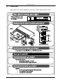
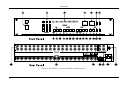
Kramer Electronics, Ltd.
USER MANUAL
Model:
VS-120
20 x 1 Sequential Video Audio Switcher
Contents
Contents
1
2
2.1
3
4
5
6
6.1
Introduction
Getting Started
Quick Start
Overview
Installing the VS-120 in a Rack
Connecting the VS-120
Controlling the VS-120
Controlling via the RS-232 Port
1
1
2
3
6
7
8
8
6.1.1
6.1.2
Connecting the RS-232 Port
Setting the Self Address
8
9
6.2
7
7.1
Controlling via the RS-485 Port
Operating the VS-120
Operating the VS-120 as a Switcher
9
10
10
7.1.1
7.1.2
7.1.3
Choosing Manual Mode
Routing an Input
Enabling and Disabling Inputs
10
10
11
7.2
Operating the VS-120 as a Scanner
12
7.2.1
7.2.2
7.2.3
Choosing Auto Mode
Scanning the Inputs
Detecting Errors
12
12
13
7.3
Operating Multiple VS-120 Units
13
7.3.1
7.3.2
Viewing the Configuration of Another Machine
Routing an Input from Another Machine
14
14
7.4
8
9
10
Operating Using Serial Commands
Technical Specifications
Hex Table
RS-232 Communication Protocol for the VS-120
15
15
16
16
Figures
Figure 1: VS-120 20 x 1 Sequential Video Audio Switcher
Figure 2: Connecting the VS-120
Figure 3: Connecting a PC without using a Null-modem Adapter
Figure 4: PC Controlling Multiple VS-120 Units
Figure 5: Multiple Unit Configuration
4
7
8
10
14
i
Contents
Tables
Table 1: Front Panel Features and Functions of the VS-120
Table 2: Rear Panel Features and Functions of the VS-120
Table 3: VS-120 Technical Specifications
Table 4: VS-120 Hex Table
Table 5: Instruction Codes for VS-120 Protocol
ii
5
5
15
16
17
KRAMER: SIMPLE CREATIVE TECHNOLOGY
Introduction
1
Introduction
Welcome to Kramer Electronics! Since 1981, Kramer Electronics has been
providing a world of unique, creative, and affordable solutions to the vast
range of problems that confront the video, audio, presentation, and
broadcasting professional on a daily basis. In recent years, we have
redesigned and upgraded most of our line, making the best even better! Our
1,000-plus different models now appear in 11 groups1 that are clearly
defined by function.
Thank you for purchasing the Kramer TOOLS VS-120 20 x 1 Sequential
Video Audio Switcher, which is ideal:
As a sophisticated alarm camera scanner
For monitoring large duplication systems
For automatic error detection in security systems
Each package includes the following items:
The VS-120 20 x 1 Sequential Video Audio Switcher
Power cord2
Windows®-based Kramer control software
Null-modem adapter
This user manual3
2
Getting Started
We recommend that you:
Unpack the equipment carefully and save the original box and
packaging materials for possible future shipment
Review the contents of this user manual
Use Kramer high-performance high-resolution cables4
1 GROUP 1: Distribution Amplifiers; GROUP 2: Switchers and Matrix Switchers; GROUP 3: Control Systems; GROUP 4:
Format/Standards Converters; GROUP 5: Twisted-Pair Solutions; GROUP 6: Specialty AV Products; GROUP 7: Scan
Converters and Scalers; GROUP 8: Cables and Connectors; GROUP 9: Room Connectivity; GROUP 10: Accessories and
Rack Adapters; GROUP 11: Sierra Products
2 We recommend that you use only the power cord supplied with this device
3 Download up-to-date Kramer user manuals from our Web site at http://www.kramerelectronics.com
4 The complete list of Kramer cables is on our Web site at http://www.kramerelectronics.com
1
Getting Started
2.1
Quick Start
This quick start chart summarizes the basic setup and operation steps.
2
KRAMER: SIMPLE CREATIVE TECHNOLOGY
Overview
3
Overview
The VS-120 20 x 1 Sequential Video Audio Switcher is a programmable
scanning video switcher that accepts up to 20 inputs when operating as a
standalone unit, sequentially cycling the 20 video and audio stereo sources.
In manual mode it operates as a switcher and in automatic mode it operates
as a scanner. The fully programmable EEPROM/NOVRAM memory saves
and recalls all user-defined setups. Specifically, the VS-120 20 x 1
Sequential Video Audio Switcher features:
Support for connecting up to 99 VS-120 units to form a
switcher/scanner with up to 1980 inputs
Control via the front panel buttons or by RS-232 or RS-485
commands transmitted by a PC, touch screen system, or other
serial controller
Switching during the vertical interval, to ensure glitch-free
transitions between genlocked sources
Fully microprocessor controlled operation
To achieve the best performance:
Use only good quality connection cables1 to avoid interference,
deterioration in signal quality due to poor matching, and elevated
noise levels (often associated with low quality cables).
Avoid interference from neighboring electrical appliances that
may adversely influence signal quality and position your Kramer
VS-120 away from moisture, excessive sunlight and dust
1 Available from Kramer Electronics on our Web site at http://www.kramerelectronics.com
3
Overview
Figure 1: VS-120 20 x 1 Sequential Video Audio Switcher
4
KRAMER: SIMPLE CREATIVE TECHNOLOGY
Overview
Table 1: Front Panel Features and Functions of the VS-120
#
Feature
1 POWER Switch
2 PROGRAM KEYS Buttons
9
ENABLED INPUTS LEDs
MACHINE 7-segment Display
INPUT 7-segment Display
DOWN Button
UP Button
SELF ADDRESS Button
Setup
3
4
5
6
7
8
AUTO Button
MANUAL Button
11
DWELL TIME Button
12
START Button
13
14
Auto Mode
10
16
17
18
19
Program
15
21
22
MACHINE NUMBER
Button
INPUT NUMBER Button
ENABLE Button
DISABLE Button
SKIP Button
STOP Button
Error
20
STOP Button
CONTINUE Button
IGNORE Button
LIST Button
Function
Illuminated switch for turning the unit ON or OFF
Use to set the values for the Machine Number, Input Number or
Dwell Time
Indicate whether an input is enabled (on) or disabled (off)
Displays the Machine Number
Displays the Input Number
Press to decrease a number by one
Press to increase a number by one
Sets the Machine # (between 1 and 99). Set a standalone machine
address to 01
Press to activate the scanner mode. Prevents using the unit as a
switcher and lights the Auto LED
Press to activate the (default) switcher mode. Prevents using the
unit as a scanner and lights the Manual LED
Sets the scan display time (range is between 2 and 99 seconds) and
flashes the current setting in the MACHINE Display
Starts scanning (only if the AUTO LED lights) from the first input of the
first machine that is in the Enable state. Dwell Time determines the
scanning time
Stops the scanning
Starts scanning from the present connected input to the output
(functions only when the AUTO LED lights)
Use to display another machine in a multiple unit configuration
Press to alter the Enable/Disable status of an input. The current
Input Number flashes in the INPUT Display
Press to light the selected Enabled Inputs LED
Press to turn off the selected Enabled Inputs LED
Skips an input after detecting a video input error during scanning
(lights the Skip LED) and continues scanning the next input
Stops scanning after detecting a video input error (lights the Stop
LED)
Scans independently of the video input signal’s characteristics (lights
the Ignore LED)
Press to produce a list (during the first scanning cycle) of the video
inputs at which a video signal is absent
Table 2: Rear Panel Features and Functions of the VS-120
#
23
24
25
26
27
Feature
AUDIO INPUTS RCA Connectors
Video Inputs BNC Connectors
Video Outputs/Loop BNC Connectors
RS-485 Terminal Block Port
Audio Outputs/Loop RCA Connectors
28 Power Connector with Fuse
29 RS-232 DB 9F Port
Function
Connects to the left and right audio sources (from 1 to 20)
Connects to the video sources (from 1 to 20)
Connects to the video acceptor(s) (from 1 to 2)
Detachable terminal block port. PINOUT from left: + - G
Connects to the left and right audio connectors on the
acceptor(s) / next unit (from 1 to 2)
AC connector enabling power supply to the unit
Connect to the PC or the Remote Controller via a nullmodem connection
5
Installing the VS-120 in a Rack
4
Installing the VS-120 in a Rack
This section describes how to install the VS-120 in a rack.
Before Installing in a rack
Before installing in a rack, be sure that the environment is
within the recommended range:
Operating temperature range 5º to 45º C (41º to 113º F)
Operating humidity range
10 to 90% RHL, non-condensing
Storage temperature range
-20º to +70º C (-4º to +158º F)
Storage humidity range
5 to 95% RHL, non-condensing
How to Rack Mount
To rack-mount a machine:
1. Attach both ear brackets to the
machine. To do so, remove the
screws from each side of the
machine (3 on each side), and
replace those screws through the
ear brackets.
CAUTION!!
When installing on a 19" rack, avoid hazards by taking
care that:
1. It is located within the recommended environmental
conditions, as the operating ambient temperature of a
closed or multi unit rack assembly may exceed the
room ambient temperature.
2. Once rack mounted, enough air will still flow around
the machine.
3. The machine is placed straight in the correct
horizontal position.
4. You do not overload the circuit(s). When connecting
the machine to the supply circuit, overloading the
circuits might have a detrimental effect on overcurrent
protection and supply wiring. Refer to the appropriate
nameplate ratings for information. For example, for
fuse replacement, see the value printed on the
product label.
5. The machine is earthed (grounded) in a reliable way
and is connected only to an electricity socket with
grounding. Pay particular attention to situations where
electricity is supplied indirectly (when the power cord
is not plugged directly into the socket in the wall), for
example, when using an extension cable or a power
strip, and that you use only the power cord that is
supplied with the machine.
6
2. Place the ears of the machine
against the rack rails, and insert the
proper screws (not provided)
through each of the four holes in the
rack ears.
Note that:
In some models, the front panel
may feature built-in rack ears
Detachable rack ears can be
removed for desktop use
Always mount the machine in the
rack before you attach any cables
or connect the machine to the
power
If you are using a Kramer rack
adapter kit (for a machine that is not
19"), see the Rack Adapters user
manual for installation instructions
(you can download it at:
http://www.kramerelectronics.com)
KRAMER: SIMPLE CREATIVE TECHNOLOGY
Connecting the VS-120
5
Connecting the VS-120
To connect the VS-120, as shown in Figure 2, do the following1:
1. Connect up to 20 video-audio stereo sources to the appropriate input video
BNC connectors and input AUDIO L and AUDIO R RCA connectors (for
example, video players 1 to 20).
2. Connect the output video BNC connectors (for example, to one or two
displays) and output AUDIO L and AUDIO R RCA connectors to up to
two audio stereo acceptors (for example, the amplifier).
3. If required, you can connect a PC and/or controller to the RS-232 or RS-485
ports (as shown below). To combine multiple units, connect them using the
RS-485 ports.
4. Connect the power cord to the mains electricity (not shown in
Figure 2).
Figure 2: Connecting the VS-120
1 Switch OFF the power on each device before connecting it to your VS-120. After connecting your VS-120, switch on its
power and then switch on the power on each device
7
Controlling the VS-120
6
Controlling the VS-120
Operate the VS-120 via the front panel buttons. You can also control the
VS-120 using the:
RS-232 port (see section 6.1)
RS-485 port (see section 6.2)
6.1
Controlling via the RS-232 Port
The VS-120 can be operated via PC, touch screen, or serial controller by
means of serial commands transmitted through the RS-232 port. For a
description of the serial commands, see section 10.
6.1.1 Connecting the RS-232 Port
To connect a PC1 to the VS-120 unit, using the null-modem adapter
provided with the machine (recommended):
Connect the RS-232 9-pin D-sub rear panel port on the Master
VS-120 unit to the null-modem adapter and connect the
null-modem adapter with a straight cable to the RS-232 9-pin
D-sub port on your PC
To connect a PC to the VS-120 unit, without using a null-modem adapter:
Connect the RS-232 9-pin D-sub port on your PC to the RS-232
9-pin D-sub rear panel port on the Master VS-120 unit, using a
cable illustrated in Figure 3.
PIN 5 Connected to PIN 5 (Ground)
PIN 3 Connected to PIN 2
PIN 2 Connected to PIN 3
Female DB9 (From PC)
Male DB9
PIN 4 Connected to PIN 6
PINS 8, 7, 1 Connected together
If a Shielded cable is used, connect the shield to PIN 5
Figure 3: Connecting a PC without using a Null-modem Adapter
1 Or a master program remote control system such as the Kramer RC-3000
8
KRAMER: SIMPLE CREATIVE TECHNOLOGY
Controlling the VS-120
6.1.2 Setting the Self Address
When controlling a unit through the RS-232 or RS-485 ports, each unit
must be identified by a unique Self Address. The first unit connected to the
PC is the master unit and its address must be 01. All other slave units must
have unique addresses from 02 to 99.
To set the self address:
1. Press the SELF ADDRESS button in the SETUP section.
The MACHINE display flashes.
2. Enter a 2-digit address using the UP/DOWN buttons or the keypad.
3. Press ENT to save the address.
6.2
Controlling via the RS-485 Port
You can control up to 99 VS-120 units via the RS-485 port using:
A Master Programmable Remote Control system such as the Kramer
RC-3000 controller
A PC that connects via its RS-232 interface to a master
VS-120 that connects up to 98 slave units through its RS-485 interface
If connecting a master VS-120 to an RS-232 port in a PC, first follow the
steps in section 6.1.
To connect an RC-3000 to a VS-120 unit, or slave units to a master
VS-120:
1. Connect the left “A” (+) PIN on the RS-485 rear panel port of the master (or
RC-3000) to the “A” (+) PIN on the RS-485 rear panel port of the
VS-120 slave unit.
2. Connect the center “B” (–) PIN on the RS-485 rear panel port of the master
(or RC-3000) to the “B” (–) PIN on the RS-485 rear panel port of the
VS-120 slave unit.
3. If shielded twisted pair cable is used, the shield may be connected to the
right “G” (Ground) PIN on one of the units (for example, on the master).
To connect up to 98 additional VS-120 slave units, via RS-485, do the
following (see Figure 4):
Connect the RS-485 terminal block port on the first VS-120 unit to
the RS-485 port on the second VS-120 unit and so on, connecting all
the RS-485 ports
Set the Self Address of the first machine to 01, the second machine
to 02, and so on, up to 99 (see section 6.1.2).
9
Operating the VS-120
Figure 4: PC Controlling Multiple VS-120 Units
7
Operating the VS-120
This section describes how to operate the VS-120:
As a switcher (see section 7.1)
As a scanner (see section 7.2)
To detect input errors (see section 7.2.3)
In multiple unit configurations (see section 7.3)
Using RS-232/RS-485 serial commands transmitted by a touch
screen system, PC, or other serial controller (see section 7.4)
7.1
Operating the VS-120 as a Switcher
The VS-120 operates as a 20 x 1 switcher when set to Manual mode. Any
of the 20 inputs can be individually selected and routed to the output. When
Manual mode is selected it prevents the scanning function from operating.
7.1.1 Choosing Manual Mode
To set the Manual mode:
Press the MANUAL button in the SETUP section
The MANUAL LED illuminates
7.1.2 Routing an Input
To route an input to the output:
1. Choose an input by pressing the UP or DOWN buttons to increment or
decrement the number in the INPUT display, then press ENT.
or,
Enter the input as a 2-digit number (01, 02, … 20) on the PROGRAM
KEYS pad, the MACHINE display flashes, then press ENT.
10
KRAMER: SIMPLE CREATIVE TECHNOLOGY
Operating the VS-120
2. To optionally choose a different machine (if using a multiple unit
configuration), enter the 2-digit input number on the PROGRAM KEYS
pad. When the MACHINE display flashes, enter the target machine
number, then press ENT.
If the MACHINE display already shows the number of the required
machine, you can press ENT immediately without pressing the
Machine #.
Example 1: If input #13 on machine #1 is connected to the output, and
you want to connect input #5 to the output, press 0 followed by 5, and
then ENT.
Example 2: If input #13 on machine #1 is connected to the output, and
you want to connect input #7 of machine #2 to the output, press 0
followed by 7, and then 0 followed by 2, and then press ENT.
7.1.3 Enabling and Disabling Inputs
You can enable or disable individual inputs by programming. The setup is
stored in non-volatile memory and is saved when the unit is powered off.
When an input is enabled, its LED illuminates in the ENABLED INPUTS
section.
To disable an input:
1. Press the INPUT NUMBER button in the PROGRAM section.
The INPUT display and the AUTO and MANUAL LEDs flash.
2. Enter the desired input and press DISABLE to disable the input.
The ENABLED INPUTS LED turns off.
3. Then press ENT. The AUTO and MANUAL LEDs stop flashing and the
MANUAL LED is steadily on.
To enable an input:
1. Press the INPUT NUMBER button in the PROGRAM section.
The INPUT display and the AUTO and MANUAL LEDs flash.
2. Enter the desired input and press ENABLE to disable the input.
The input LED turns on.
3. Then press ENT. The AUTO and MANUAL LEDs stop flashing and the
MANUAL LED is steadily on.
11
Operating the VS-120
7.2
Operating the VS-120 as a Scanner
The VS-120 operates as a 20 input scanner when set to Auto mode. The
VS-120 scans all enabled inputs, one after another, for the amount of time
programmed in the Dwell Time setting and routes the input to the output.
Any enabled input that does not have a video signal is logged in the Error
List memory that can later be displayed.
When Auto mode is selected it prevents the switching function from
operating.
7.2.1 Choosing Auto Mode
To set Auto mode:
Press the AUTO button in the SETUP section
The AUTO LED illuminates
7.2.2 Scanning the Inputs
Dwell time determines how long each input is displayed during the scan. To
set the dwell time:
1. Press the DWELL TIME button in the AUTO MODE section.
The MACHINE display flashes.
2. Set the dwell time in seconds from 2 to 99 by pressing the UP/DOWN keys
or the PROGRAM KEYS.
3. Press ENT to save the number.
To begin an automatic scan:
Press the START button in the AUTO MODE section
The Input display begins to increment automatically as it scans the
inputs and the AUTO LED flashes
To stop the scan:
Press the STOP button in the AUTO MODE section
The Input display stops on an input and the AUTO LED
illuminates steadily
To continue the scan from the displayed input:
Press the CONTINUE button in the AUTO MODE section.
The Input display increments from the displayed input and the
AUTO LED flashes
To restart the scan from input 01:
Press the START button in the AUTO MODE section.
The Input display begins to increment automatically as it scans the
inputs and the AUTO LED flashes
12
KRAMER: SIMPLE CREATIVE TECHNOLOGY
Operating the VS-120
7.2.3 Detecting Errors
While scanning, the VS-120 senses missing video inputs, illuminates the
LIST LED in the ERROR section, and stores the errored input number in
memory. The list is erased and initialized every time a new scan is begun.
To stop an active scan when an error is detected:
Press the STOP button in the Error section
The STOP LED illuminates when an error is detected and the scan
is stopped
To skip an errored input:
Press the SKIP button in the Error section
The SKIP LED illuminates when an error is detected and the scan
continues
To ignore an input error:
Press the IGNORE button in the Error section
The IGNORE LED illuminates and the scan continues regardless
of errors
Note: To change the error Skip, Stop, and Ignore settings, scanning must be
stopped by pressing the STOP button in the AUTO MODE section.
To display the list of errored inputs:
1. Press the STOP button in the AUTO MODE section to stop the scan.
2. Press the LIST button in the Error section.
The Machine and Input displays flash the numbers of the machine and first
input that has an error.
3. Press the UP button to display the input errors one after another.
4. You can delete each error from the list by pressing the DEL button in the
Program Keys section. When the list is empty, the LIST LED turns off, the
display stops flashing, and the last scanned input shows in the display.
7.3
Operating Multiple VS-120 Units
Multiple unit configurations of the VS-120 can be created to increase the
number of outputs switched or scanned. Two VS-120s can be combined to
create a 40 x 1 switcher/scanner, three units can combine into a 60 x 1
switcher/scanner, and so on, up to 99 VS-120s. The multiple unit
configuration is seen as one large switcher/scanner.
The units must be connected via their RS-485 ports (see section 6.2). The
first VS-120 must have Self Address 01 and following machines must have
13
Operating the VS-120
unique addresses (see Figure 5). The outputs from all the machines can be
tied together to create one output for the multi-unit machine.
Figure 5: Multiple Unit Configuration
7.3.1 Viewing the Configuration of Another Machine
The configuration of any machine can be viewed from any other machine to
see which inputs are enabled or disabled.
To view the configuration of another target machine:
1. In Manual mode, press the MACHINE NUMBER button in the
PROGRAM section.
The MACHINE display and the AUTO and MANUAL LEDs flash.
2. Enter the address of the target machine using the UP or DOWN buttons or
the PROGRAM KEYS, and press ENT.
The AUTO and MANUAL LEDs stop flashing. The MACHINE display
also stops flashing and shows the address of the target machine.
The LEDs of the Enabled Inputs display the active inputs on the target
machine.
7.3.2 Routing an Input from Another Machine
To route an input from a target machine (in Manual mode):
1. Using the PROGRAM KEYS (the UP and DOWN keys won’t allow
selection of a different machine), enter the desired output from 01 to 20 on
the target machine.
The input display shows the target input and the MACHINE display flashes.
2. Enter the target machine address using the PROGRAM KEYSS and press
ENT.
The MACHINE display stops flashing and the target input is routed to the
output.
14
KRAMER: SIMPLE CREATIVE TECHNOLOGY
Technical Specifications
7.4
Operating Using Serial Commands
To operate your device using serial commands, install Kramer'
s control
software (K-Router) that can be downloaded from the Kramer Electronics
Web site1.
For an explanation of the RS-232 protocol and all serial commands, see
section 10.
8
Technical Specifications
The VS-120 technical specifications are shown in Table 3:
Table 3: VS-120 Technical Specifications
INPUTS:
20 video, 1Vpp /75
RCA connectors.
OUTPUTS:
1 video, 1Vpp/75 on 2 BNC connectors, connected in parallel; 1 audio
stereo, 1Vpp/100 on 2x2 RCA connectors, connected in parallel; RS-232
on a 9-pin D-sub connector; RS-485 on a 3-pin terminal block connector.
4 seven-segment display LEDs, 20 LED status display.
12-key keypad control, 17 touch switch setup controls, RS-232, RS-485.
Vertical interval.
1–60s.
Sync detection.
25MHz (-3dB).
20kHz (-1dB).
1.3%.
<0.05%.
19" x 7" x 2U W, D, H, rack mountable.
230V AC, 50/60Hz (115V AC, U.S.A), 6.7VA.
4.1kg (9.1lbs) approx.
Power cord, Windows®-based control software, null-modem adapter.
DISPLAY:
CONTROL:
SWITCHING:
DWELL TIME:
ERROR DETECTION:
VIDEO BANDWIDTH:
AUDIO BANDWIDTH:
DIFF. GAIN:
K-FACTOR:
DIMENSIONS:
POWER SOURCE:
WEIGHT:
ACCESSORIES:
on BNC connectors; 20 audio stereo, 1Vpp/50k
on
1 www.kramerelectronics.com
15
Hex Table
9
Hex Table
Table 4 lists the Hex values for the VS-120 (see section 10 for more detail):
Table 4: VS-120 Hex Table
Inputs
10
Inputs
IN 1
IN 2
IN 3
IN 4
Switch Commands
(Hex)
40 80 81
40 80 82
40 80 83
40 80 84
IN 5
40 80 85
IN 15
40 80 8F
IN 6
40 80 86
IN 16
40 80 90
IN 7
40 80 87
IN 17
40 80 91
IN 8
40 80 88
IN 18
40 80 92
IN 9
40 80 89
IN 19
40 80 93
IN 10
40 80 8A
IN 20
40 80 94
IN 11
IN 12
IN 13
IN 14
Switch Commands
(Hex)
40 80 8B
40 80 8C
40 80 8D
40 80 8E
RS-232 Communication Protocol for the VS-120
RS-232 communication with the VS-120 is done using three bytes of
information as defined below. The data rate is 9600 baud, no parity, 8 data
bits, and one stop bit.
Byte 1:
0
7
x
5
x
4
x
6
x
5
x
4
ADDRESS
x
3
x
6
x
5
x
4
DATA
x
3
Byte 2:
1
7
Byte 3:
1
7
COMMAND
x
x
3
2
x
6
x
1
x
0
x
2
x
1
x
0
x
2
x
1
x
0
DETAILED DESCRIPTION
Byte 1
Byte 1, bits 0 to 5 = COMMAND number = CODE (listed below)
Byte 1, bit 6 = Destination bit:
When the PC sends a message to the machine, this bit must be 1
When the machine sends a message to the PC, this bit must be 1.
If this bit is 0, this message is not destined for the PC.
Byte 1, bit 7 must be 0.
16
KRAMER: SIMPLE CREATIVE TECHNOLOGY
RS-232 Communication Protocol for the VS-120
Byte 2
Byte 2, bits 0 to 6 = ADDRESS. These bits describe the Machine number that is influenced by COMMAND.
The number of machine can be from 1 to 99 (hex). 1 = Master.
Byte 2, bit 7 must be 1.
Byte 3
Byte 3, bits 0 to 6 = DATA. These bits describe the DATA that is influenced by COMMAND.
For example, to connect input 17 to output, the DATA should be 17( hex ).
Byte 3, bit 7 must be 1.
Table 5: Instruction Codes for VS-120 Protocol
Note: All values in the table are hex, unless otherwise stated.
Code
Command
Address
Data
Replay
00
CONNECT INPUT TO OUTPUT
Machine number
Input number
Nonessential
01
GET STATUS - WHICH INPUT IS
CONNECTED TO OUTPUT
0
0
COMMAND – As sent 01
ADDRESS – Machine connected
DATA – Input number
02
SET ALL MACHINES TO AUTO
OR MANUAL MODE
0
1 – Auto
0 – Manual
Nonessential
03
GET THE STATUS OF
MACHINES AUTO OR MANUAL
MODE
0
0
COMMAND – As sent 03
ADDRESS – As sent
DATA – 1 for Auto mode
– 0 for Manual mode
04
SET DWELL TIME OF SCANNING 0
2 – 99
Nonessential
05
GET DWELL TIME OF SCANNING 0
0
COMMAND & ADDRESS – As sent
DATA – Dwell time 2–99
06
START SCANNING
0
0
Nonessential
08
STOP SCANNING
0
0
Nonessential
09
CONTINUE SCANNING
0
0
Nonessential
0A
ENABLE INPUT FOR SCANNING
Machine number
Input number
Nonessential
0B
DISABLE INPUT FOR SCANNING
Machine number
Input number
Nonessential
0C
GET THE STATUS OF INPUT
ENABLE OR DISABLE
SCANNING
Machine number
Input number
COMMAND – 0A for Enable
– 0B for Disable
ADDRESS & DATA – As sent
16
SAVE THE STATUS OF INPUT
ENABLE OR DISABLE
SCANNING
Machine number
0
Nonessential
0D
SET ERROR STATUS SKIP,
STOP, OR IGNORE
0
0 – Skip
1 – Stop
2 – Ignore
Nonessential
0E
GET ERROR STATUS SKIP,
STOP, OR IGNORE
0
0
COMMAND & ADDRESS – As sent
DATA – 0 for Skip
– 1 for Stop
– 2 for Ignore
0F
GET THE NUMBER OF LIST OF
ERROR
0
0
COMMAND & ADDRESS – As sent
DATA – Number of errors
10
GET ERROR NUMBER X
(0 – LAST ERROR)
0
Error number
COMMAND – As sent
ADDRESS – Machine number
DATA – Input number of error
12
DELETE ALL ERRORS
0
0
Nonessential
17
RS-232 Communication Protocol for the VS-120
EXAMPLES FOR USING THE PROTOCOL:
1) To connect input 8 in machine 2 to the output, set the bytes as below:
Byte 1 – 40(hex) + COMMAND
= 40 + 00 = 40(hex).
Byte 2 – 80(hex) + ADDRESS(hex) = 80 + 02 = 82(hex).
Byte 3 – 80(hex) + DATA(hex)
= 80 + 08 = 88(hex).
2) To change the machines status to "Auto" mode, set the bytes as below:
Byte 1 – 40(hex) + COMMAND
= 40 + 02 = 42(hex).
Byte 2 – 80(hex) + ADDRESS(hex) = 80 + 00 = 80(hex).
Byte 3 – 80(hex) + DATA(hex)
= 80 + 01 = 81(hex).
3) To get the Dwell time of scanning, set the bytes as below:
Byte 1 – 40(hex) + COMMAND
= 40 + 05 = 45(hex).
Byte 2 – 80(hex) + ADDRESS(hex) = 80 + 00 = 80(hex).
Byte 3 – 80(hex) + DATA(hex)
= 80 + 00 = 80(hex).
Reply:
The reply to this command is identical to the three bytes which were sent.
For example:
Byte 1 – 45(hex).
Byte 2 – 80(hex).
Byte 3 – 94(hex).
Therefore the Dwell time = 94(hex) - 80(hex) = 14(hex) = 20(dec).
4) To start scanning set the byte as below:
Byte 1 – 40(hex) + COMMAND
= 40 + 06 = 46(hex).
Byte 2 – 80(hex) + ADDRESS(hex) = 80 + 00 = 80(hex).
Byte 3 – 80(hex) + DATA(hex)
= 80 + 00 = 80(hex).
Notes:
1) Use the COMMAND "Connect input to Output" only in "Manual" mode.
2) Use the COMMAND "Start scanning" or "Continue scanning" only in "Auto" mode.
3) The two LEDs of "Auto" and "Manual" go out when using the COMMAND "Enable input for scanning"
or "Disable input for scanning" until using the COMMAND "Save the status of inputs, Enable or Disable
scanning"
4) Use the COMMAND "Save the status of inputs, Enable or Disable scanning" after using the
COMMANDs "Enable input for scanning" and "Disable input for scanning".
18
KRAMER: SIMPLE CREATIVE TECHNOLOGY
19
For the latest information on our products and a list of Kramer
distributors, visit our Web site: www.kramerelectronics.com
where updates to this user manual may be found.
We welcome your questions, comments and feedback.
Safety Warning:
Disconnect the unit from the power supply before
opening/servicing.
Caution
Kramer Electronics, Ltd.
Web site: www.kramerelectronics.com
E-mail: [email protected]
P/N: 2900-002026 REV 3