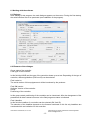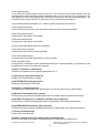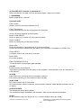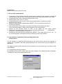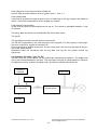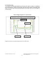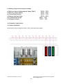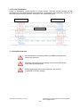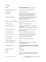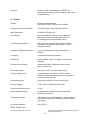
1
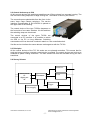
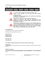
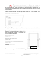
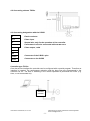
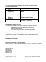
Illumination Control Device 4.0 24.11.2011 Table of Contents 1 2 General Description 2.1 19 Inch Rack 2.2 Control Device up to 50 amp 2.3 3 Controlling Priciples Range of Applications 3.1 Application possibilities 3.2 Table of Workloads for the Control Device 3.3 3.4 Practical Hints Mounting 3.5 Different kind of racks 4. Connection schematics for the racks 4.1 4.2 Wall housing Connections sceem for TIC50s 4.3 Connection significations for the contol device TIC50s 5.1 Status of the LED will be declared by internal variables by the mode of the control device Configuration Software (Version 2.0) 5.3 Content and functional mode of the software 5.4 5.5 Software installation Copying of the Program on the targeted PC 5.6 Linkage on the Desktop PC (not mandatory) 5.7 Adding of the program in to the starting menue 5.8 6.1 Building up of a serial interface Dialogue 6.2 Elements of the dialogue 8 Logical functions, print out of the operational data of the control device 8.1 Configuring of the LOG-functions 8.2 Oprerarations via S-Bus, type TIC50s 8.3 Controlling range 9 Dimming of the different type of lamps 10 Applications examples 10.1 Street illumination 10.2 Tunnel illumination 12 TIC50s 12 TIC50m 12.1 TIC15s User Manual TIC2081708, 24.11.2011 CEAP Electronics GmbH, Switzerland- 4566 Kriegstetten Email: [email protected] -2- 1. General The persent user manual is intended as a introduction step by step into the function, application and operation of the illumination control device TIC series. It serves as a basis at the planning, mounting and operation of the illumination control devices. It applies only for the described types. Because of further developement the data of further types can by diffrent. The resulting high quality shows despite of all carefulness certain limits, e.g. a natural wearing out of components has to be considered. For such elements we deliver a functional warranty (visible in our delivery conditions). The customer has to contribute his part for the reliable operation of the illumination control units. The customer is responsible that those control devices are used in a appropriate manner and to avoid careless usage (e.g. temperature ranges, over voltage and desturbing magnetic fields do occour). Furthermore, the user is also responsible that a product out of order in no case leads to violations of even the death of persons or leads to destroing of material goods. The appropirate security prescriptions have to be observed in any case. Under the lookout-sign, you will find hints to be observed. If all this points are observed, the user will have with the TIC illumination control gear a modern and secure product which will control you illumination reliably. 2. Descriptions The TIC product series represents an universal, digital, compact and price worthy illumination control device. Its prime quality is a result of micro processor controlled curves. By this is perfect for NAH lamps. It also can be used for other ordenary tyes of lambs. This devices are offered with switching performances up to to 15 A and up to 50 A. Control device up to 15 A The type of up to 15 A switching capacity (TIC15s) is offered in the europiean printed card formats. A 19 inch rack can comprise a maximum of 6 control devices. The control devices are connected via plugs with the backplane. All the connections are made via backplane: User Manual TIC2081708, 24.11.2011 CEAP Electronics GmbH, Switzerland- 4566 Kriegstetten Email: [email protected] -3- -Power conductor -Lamp connections -Power supply of 24VDC -Data bus On the front plate are two service connectors RJ11/RS 232 and two control LEDs. Via this interface all the controllers are adressed, switching steps are introduced before operation and all service functions can be consulted concerning operating statuses can be gained. 2.1 19’’inch rack size: 84 TE maximum of 6 control cards All connections on the back plane correspond to the technology of vago cage and clamp and are placed on the reverse side of the back plane. The connectors for the power allimentation of 24VDC and the BUS are connected via this printed circuit. On the back plane are all data and parameters of the single cards (controllers). The singel controllers may therefore be freely exchanged without changing the prepositioning. This is a big advantage in case of repairs. User Manual TIC2081708, 24.11.2011 CEAP Electronics GmbH, Switzerland- 4566 Kriegstetten Email: [email protected] -4- 2.2 Control devices up to 50A All this control devices with switching capacities over 15A are placed in a seperate housing. The wall mounted casing desposes of large cooling fins. The fixation is done by two screws. The connections are admissable from the front vie the same Vago Cage Clamps technique. The service interface corresponding to RJ11/RS232 is placed on the upper side of the housing. The control device of the type TIC50m desposes on the front side of two raster switches. Via this switches the switching steps are introduced. The control devices of the types TIC50s are connected to a PC interface. It is possible to switch via SPS or via PC on long distances. Switching commands on/off can be ruled via electric watch or a net controlled switch. Via this service interface the same data are exchanged as with the TIC15s. 2.3 Principles All the control devices of the TIC XX series are one phased controllers. This means that for each and every interface a sperate control device is needed. The control devices are built up as modified as phase cutting controllers. The triac element will best be activated during the zero transitions. 2.4 Survey Scheme Relais FL S-Bus Driver Or digital port IN Triac Processor Trigger Powersupply User Manual TIC2081708, 24.11.2011 CEAP Electronics GmbH, Switzerland- 4566 Kriegstetten Email: [email protected] -5- 3. Range of operations The illumination control devices are used as well for existing illumination elements as also for new illumination elements. 3.1 Applications possibilities ● Street illuminations At streets of communities as also at highway illuminations, depending on variables as day- night and dimming times (outside brightness), depending also on traffic densintiy, climatical conditions with different visibilities. ● Tunnel illumination control devices In the zones of eye adaptions and at the lower transit illumination depending on the conditions of variable driving speeds and danger indications, the actual outside brightness at the sides of inlet and outlet. The deminishing brightness of the tunnel walls due to increasing darkness caused by increasing pollution etc. ● The illumination of underbridges Depending on the same variables like outside brightness at inlet and outlet the dynamically indicated driving speeds and danger indications and depending on the brightness of the inside walls. ● Outside illuminations of factory sites and storing premisses This illumination depends on outside brightness and kind of usage of such premises. Reduction of light influences on the surrounding during different day times. ● Illumination of vast industry halls Illumination depends on outside brightness, kind of usage, shift plans, day times, number of present persons etc. ● Commercial plant growing In connection with specil lamps e.g. Planta-Star of Osram for the commertial growing of plants. The applications possibilities of the Illumination control devices are of course not limited to the named classical application. Everywhere, where a bigger group illimination elements promise a considerable power reducing by needes variable illumination intensitiy. The application of such controllers is justified. User Manual TIC2081708, 24.11.2011 CEAP Electronics GmbH, Switzerland- 4566 Kriegstetten Email: [email protected] -6- 3.2 Table of power usage for the different controllers TIC50s / TIC50m Lamps Starting power Max. no of lamps 70 watts 1.3A 34 units 100 watts 1.56 A 30 units 150 watts 2.34 A 20 units 250 watts 3.9 A 12 units 400 watts 5.98 A 6 units 1. In case the types of lamps are mixed, the nominal power charge of the controller can not exeed the total capacity. System premisses to garantee a flawless functioning of the controllers the following points have to be observerd: Compensation capacitors of the illumination elements are harmful the controllers. They must be eliminated from the illuminations elements. A possibly needed compensation has to be realised by the controller. The NaH lamps supplied by the producer under 70 Watt (70 Watt only up to 50 %) are not allowed for dimming. In case of operation of a system with different lamp performances, there exists a risk that 50 Watt lamps are extinguished. That is why the operation of lamps under 70 watts is only possible on the users own risk. 3.3 Practical hints From different net users we got the following hints: NAH lamps with good experienced values: Phillips SON 70 Phillips SON 100 Phillips SON 150 Phillips SON 250 Osram NAV 100 Osram NAV 150 Osram NAV 250 The suppliers of Sylvania products permit only a reduced control range. 3.4 Mounting The control devices are generally built in a way that the mounting is possible with the customers personel. 3.5 Rack conception The mounting of the 19 inch racks is best done with a shivering crane. This is improving the connection of the different conducting cables. It is also advantageous in case of looking for errors. User Manual TIC2081708, 24.11.2011 CEAP Electronics GmbH, Switzerland- 4566 Kriegstetten Email: [email protected] -7- The controllers must be cooled in a efficient way. Between the single racks a distance of a minimal rack highness is to be let free. All the connections are placed along scheme on the reverse side of the rack. After the connection of the outsides conductors after the printed circuits have to be inserted in the rack from the front part. Over the interfaces from the front plate the printed circuits have to be adressed. Those addresses are stored via the card on the back plane. 4. Connection scheme on the rack 4.1 Wall housing The controllers are fixed directly on the wall. This can be placed as adjacent to the distribution or on the back side of the control box. The controller ist mounted via connections clamps downside. The fixation is done by two screws. For a simple mounting or exchange of a controller the following screws are admissable: Slotted head wood screw (max. 4.5 mm) Slotted pan head tapping screw (max. 4.8 mm) Raised countersunk recessed head tapping screw (max. 4.8 mm) Hex headed inboard screw (max. M5) Connecting terminals The connecting clamps are of the WAGO-TOPJOPs type. User Manual TIC2081708, 24.11.2011 CEAP Electronics GmbH, Switzerland- 4566 Kriegstetten Email: [email protected] -8- 4.2 Connecting scheme TIC50s 4.3 Connecting designation with the S-BUS E Earth conductor L IN Phase input N Neutral wire, only for the operation of the controller. L OUT Performance not to be connected with actuator zero + Phase output, ruled K1 K2 S-Bus+ S-Bus Connector of the S-BUS+ plus Connector on the S-BUS Controller type TIC50s Over the service interface the controller can be configured with a special program. Therefore an interface is needed. The performance reduction and the lamp type are programmed in the controller via PC. The time of switching in the normal operation is performed via K1/K2 (e.g. timer, or net commands etc). Automatic controller User Manual TIC2081708, 24.11.2011 CEAP Electronics GmbH, Switzerland- 4566 Kriegstetten Email: [email protected] -9- 5.1 The condition the status LED is set on the basis internal variable the automatic controller mode. Pos. 1. 2. 3. 4. Condition of the control device 1: Preheating 2: Launching 3: Heating-up 4: Performance reduction 5: stable performance 6: increase performance 7: Power failing 8: wait out 9: error out 0: out 5. blinking schematics LED is blinking signs, 1/3 of the time period (Performance gets reduced) LED glows (performance is stable) LED is blinking 2/3 of the time period (Performance gets increased) LED glows twice then stops (controller has a current error) LED remains dark (controller is switched off) 5.2 Configuration software (Version 2.0) In this document the software for configuering of the power controllers is described. Reading and announcing of the actual status of the controllers. Configuration of the controller Setting up of a log-file for long term supervision of the controller 5.3 Conception and functionality of the software The software was written under Windows Visual C++ The communincation with the controller is done by the serial interface via opto interface. 5.4 Installation of the software 5.5 Copying of the program on the connectet PC. On the connected PC a new file has to be opened, e.g. in the list of program files an indication with the number “signaltes0” The following data have to be copied into this file: ● ReglerConfig0.exe ● MFC42D-DLL ● MFC042D.DLL ● MSVCIRTD.DLL ● MSVCRTD-DLL User Manual TIC2081708, 24.11.2011 CEAP Electronics GmbH, Switzerland- 4566 Kriegstetten Email: [email protected] - 10 - 5.6 Setting up of a patchwork on the Desktop Computer (not mandatory) On the desktop the left key of the mouse klicks on “new” and “patching”. The location of the storage has to be indicated as file controller config0. Further steps along the menue indications. 5.7 Introduction of the program into the starting menu ● In the starting menu “Einstellungen”, “Taskleiste” und “Startmenu” to be selected. ● Selection of the starting menu key for adaption has to be done. ● Adding and selecting ● In the field “durchsuchen” to click on the file “regler config0.exe” ● Continue along the menu. 5.8 Positioning of a serial interface After installation the serial interface has to be positioned. After activating the button “config” dialog for positioning of the interfaces shows up. (Interface COM1, COM2) User Manual TIC2081708, 24.11.2011 CEAP Electronics GmbH, Switzerland- 4566 Kriegstetten Email: [email protected] - 11 - 6. Working with the software 6.1 Dialogue After starting of this program, the main dialogue appears on the screen. During the first startup, the serial interface has to be postioned (see installation of the program). 6.2 Elements of the dialogue Group: data of the controller Field: type of the controller In this field the HWID and the type of the controller shows up as a text. Depending of the type of controller, different guidelines (SW-func.ID) can be selected. Field: serial no. The serial number of this equippenment will be introduced by the producer. Field SW version Software Version of the controller Group: Positioning of the controller In this group certain postitioning of the controller can be introduced. After the changement of the parameters all data is actual a soon as in the field program a status is indicated. Field: Headline In this field the headline of a controller can be selected (SW funk ID) The selection of the headline depends on the foreseen workload. In this list only headlines are contained which are indicative for this controller. User Manual TIC2081708, 24.11.2011 CEAP Electronics GmbH, Switzerland- 4566 Kriegstetten Email: [email protected] - 12 - Field: minimal power In this field the minimal power must be set up. Is the current for the lamps smaller than the minimal power, than the lamps getting activated again ore are obivous “out of operation”. For the setting up of the minimal power the controller is conducted on the minimal performance. The minimal current is set up as 60% of the power, set up at minimal performance. Is the minimal power allocated on “0”, than the power supervision is turned off. Field: Initial performance In this field the performance is set up for the case none of the inputs is selected. Field: Performance Input1 Performance if the input1 is activated Field performance input2 Performance if the input2 is activated Group: actual operational data of the controller Field: performance needed Performance should be manually indicated. Field: Actual performance Corresponds to the actual performance of the controller Field: Controller mode At this place is indicated in which operational status the controller actually is. Depending of the headlines only some few modes are required. (0) OFF: Controller is switched off controller is switched off the required performance is “0” (1) Heating up, lamp gets heated up heating up at special types of lamps (2) STARTING UP lamps get started Starting up activating of the lamps (3) Heating – lamps get heated The lamps gets heated before the performance can be can reduced (e.g. NaH lamps) (4) Reduce Performance gets reduced Performance gets reduced (needed performance is smaller than the actual performance) (5) STABLE Performance is stabilized (needed value is attained). Performance is stable (needed performance corresponds to the actual performance) (6) INCREASING Performance gets increased. Performance gets increased (needed performance is higher than the actual performance). (7) Power misfuncitioning Power failure has occured (8) WAIT Cooling down of the lamps before activating them Due to a new start of the lamps, the lamps has to be cooled down (switched off). User Manual TIC2081708, 24.11.2011 CEAP Electronics GmbH, Switzerland- 4566 Kriegstetten Email: [email protected] - 13 - (9) FAILURE OFF Controller is switched off After several trials, the lamp could not be started again. Lamp is out of order. (..) UNKNOWN Mode of operation is unknown. Unknown mode Field: current Actual current for the lamps indicated in mA. Field: Temperature Actual temperature at the the cooling fins of the controller. Group: Servicing elements of the programs Button: COM ON/OFF Button to switch on or switch off of the communication Button CONFIG Button for configuering of the serial interface Button LOG Button for switching on and switching off of the log functions. In case the function is switched on, the status of the controller is inscribed in to a EXEL-File. Button RESET A software reset of the controller is executed. Button END End of the program Field: PROGRAM STATUS The actual status of the program gets indicated: (10) OFF Communication is switched off This status is indicated after the startup of the program. Communication must be switched on COM ON/OFF. (8) COM Open ERR, error occured at the communication interface Error during switching on of the communication interface (6) NO COM No communication with the controller No communication with the controller, communication interface, cable and the controller have to be tested. (4) EDIT/UPDATE The introduced values getting added The introduced values are added in the controller. Wait until this indications vanishes. (0) OK All the indicated values are actual. All is o.k. All the indicated values are actual User Manual TIC2081708, 24.11.2011 CEAP Electronics GmbH, Switzerland- 4566 Kriegstetten Email: [email protected] - 14 - (x) Unknown Status it’s not known (unknown error) 7. Set up of the control device 1. Connection of the computer with the control device, starting up the program, activate the communication, after a couple of seconds the data of the control device have to be visible. 2. Characteristic line of the control device have to be set up 3. Minimal power to be set on “0” (zero) 4. Initial performance has to be set on the minimal performance, to which the conrtrol device has to be set up. 5. Reset the control device (operate button RESET). The control device should now function the right way. 6. Wait until the point of time where the actual performance has attained the value of the initial performance. Please notify the power of the control device. 7. Setting up the minimal power on 60% of the power for the control device. 8. Setting up of the performance values, which is the inital performance, performance of input no. 1 and performance of input no. 2. 9. Resetting of the control device (operate button RESET). The control device is now set up for normal operation. Eventually control of functioning of the control device. 8. Logic function, registration of the operating data of the control device For the purpose of controlling the functioning of the control device and for the purpose of making out of mistakes, the actual operating data of the control device may be logged in a special file. The logging function will be switched off and switched on by the button log in the frame of the main dialogue. 8.1 Configuering of the log functions By operating of the button “config” within the main dialogue, the following remark will appear: “Configuring of the serial interface and log-file”. User Manual TIC2081708, 24.11.2011 CEAP Electronics GmbH, Switzerland- 4566 Kriegstetten Email: [email protected] - 15 - Field: Selection of the serial interface (COM-Port) Into this field the serial interface must by typed in (com 1, com 2...). Field: Adding data If this field is activated, the data at point of time of switching on the log functions will added to the file. If this field is deactivated, all the old data are cleared. Field: Interval of protocolling In this field the interval of protocolling can be set up. The interval is selectable between 1 and 60 minutes. The set up data are stored in the initialisation file and remain stored. The log file The log data are stored in the file with the name log.xls. The file will be generated in the main directory of the program. For the purpose of archiving it has to be renamed or copyed in to another file. Every log sequence begins at the point of time of start and a title line with the data of the setups of this control device. Afterwards follow the inscriptions with the log data. One log file can contain several log sequences. 8.2 Operation via S-Bus, Type TIC 50s Via the S-Bus the control device can be dynamically operated from distance. The bright-ness can by this method adapted in real time. The comuputer changes its values based on influence of brigthness sensors, systems of higher levels, fire alarms, manual intervention etc. Guidance Systems Power Net Sensor Computer/Pc Control device Manual User Manual TIC2081708, 24.11.2011 CEAP Electronics GmbH, Switzerland- 4566 Kriegstetten Email: [email protected] - 16 - 8.3 Controlling range The maximum controlling range depends on the kinds of the lamps in usage. It is possible to control different kind of lamps with one single control device. The control device nevertheless has to be reduced on this kind of lamps which has the smallest range of controlability. Also lamps of the same kind but with diverse performances (in the same net), are only controllable in a reduced range. Power/voltage diagram of a control device Control device 1 power voltage TIC 51a K1=6 S/N 200310/016 Power 100% Power 60% Voltage 100% Voltage 91% Diagram stemming of a practical measurement of the AEW works. User Manual TIC2081708, 24.11.2011 CEAP Electronics GmbH, Switzerland- 4566 Kriegstetten Email: [email protected] - 17 - 9. Dimming range of several types of lamps ● Natrium steam highpressure lamps (NaH) ● Mercury steam lamps ● Conventional bulps ● Energy savings bulps ● Fluoressence lamps ● Halogene lamps 100% - 30% 100% - 50% 100% - 10% 100% - 85% 100% - 10% 100% - 10% 10. Examples of applications 10.1 Street illumination User Manual TIC2081708, 24.11.2011 Control device L3 Control device L2 Control device L1 Street sector with arc lamp illumination. One control device per phase. CEAP Electronics GmbH, Switzerland- 4566 Kriegstetten Email: [email protected] - 18 - 10.2 Tunnel illumination Usage of illumination control devices in street tunnels. Seperate control devices for the illuminations in the adaptions and transit sections. Conntections and controlling operations of the single control devices via BUS. Computer in the operational center. Adaptions illuminations Adaptions illuminations Transit illumination 11. Preventive measures All prescriptions concerning electrical installations and security have to be observed. Mounting, connection and exchange of the control devices has to be done by professionals. Before beginning of works on the devices, this must be (if possible) out of any voltage. User Manual TIC2081708, 24.11.2011 CEAP Electronics GmbH, Switzerland- 4566 Kriegstetten Email: [email protected] - 19 - 12. TIC50s Design: as wall mounted casings Dimensions: 220 x 145 x 80 mm (HxBxD) Reading and writing of data: via S-BUS paritiy, data, MOD-Bus ASCII Microprocessor: 3,68 MHz ATmega 128 Surveillance: the surveillance of power and temperature reduces the switching performance in case of exeeding the normal maximal values Switching performances: Max. 50A with the corresponding Opto-TRIACs Conductor cross section up to 10mm² (under sufficient cooling) Switching impulses alternatives: via net commands with local clock timers or sensors Activation (option): via potential free relay contacts Control of performance: via S-Bus (or Mod-Bus) with connected SPS or PC system Net command with local clock timers or sensors Principle of controlling: phase shift control 3 different control curves NaH, FL and bulps Controlling range: 100% up to 20% of the full performance Control reaction time: full performance from 20% to 100% in about 3 minutes. Dimming in about 20 minutes. Connection plugs: Spring clips of 10mm² and 2,5mm² Control voltage: 5 VDC from controllers power supply Power consumtion/control: 90 mA High voltage protection: An appropriate protection has to be inserted Externally (observe λ) Temperature range: -20 Degree C up to 60 Degrees C, at air humidity of 40%. Dew not permittet, sufficient cooling needed (air stram). Conductor capacity: max. 600 nF MTBF: 50 000 hours Option: in case of a defienciency of a device, an additional module is obtainable to bypass the device out of order User Manual TIC2081708, 24.11.2011 CEAP Electronics GmbH, Switzerland- 4566 Kriegstetten Email: [email protected] - 20 - Analysis: By aid of a SD-Card, data go on a EXEL file Storage and is read by a PC (voltage, power, value, operational time) 12. TIC50m Design: as wall mounted casings Dimensions: 220 x 145 x 80 mm (HxBxD) Possible via service interface: via S-BUS paritiy, data, MOD-Bus ASCII Micro processor: 3,68 MHz ATmega 128 Survaillance: the supervaillance of power and temperature reduces the switching performance in case of exeeding the normal maximal values Switching performances: Max. 50A with the corresponding Opto-TRIACs Conductor cross section up to 10mm² (under sufficient cooling) Switching impulse alternatives: via net commands with local clock timers or sensors Activation: via potential free relay contacts Setting ups: via 2 switches, each of 16 steps, or via service interface Principle of controlling: phase shift control 3 different control curves NaH, FL and bulps Controlling range: 100% up to 20% of the full performance Control reaction time: full performance from 20% to 100% in about 3 minutes. Dimming depending on set up control curves (max 20 minutes). Connection plugs: Spring clips WAGO of 10mm² and 2,5mm² Control voltage: 5 VDC from controllers power supply Power consumtion/control: 90 mA High voltage protection: An appropriate protection has to be inserted Externally (observe λ) Temperature range: -20 Degree C up to 60 Degrees C, at air humidity of 40%. Dew not permittet, sufficient cooling needed (air stram). Conductor capacity: max. 600 nF MTBF: 50 000 hours User Manual TIC2081708, 24.11.2011 CEAP Electronics GmbH, Switzerland- 4566 Kriegstetten Email: [email protected] - 21 - Option : in case of a defieciency of a device, an additional module is obtainably to bypass the device out of order Analysis: With aid of a SD-Card data go on a EXEL file Storage and is read by a PC (voltage, power, value, operational time) 12.1 TIC15s Design: TIC15s rack mounted, Euro card format Reading and writing of data: via S-BUS paritiy, data, MOD-Bus ASCII Micro processor: 3,68 MHz ATmega 128 Survaillance: the supervaillance of power and temperature reduces the switching performance in case of exeeding the normal maximal values Switching performances: 17A Digital activation: option via potential free relay contacts only 2 steps Performance control: via S-BUS (or Mod-Bus) from connected SPS or PC systems (Ethernet in preparation) Princip of controlling: phase shift control 3 different control curves NaH, FL and bulps Controlling range: 100% up to 20% of the full performance depending on lamp type Control reaction time: full performance from 20% to 100% in about 3 minutes. Dimming depending on set up control curves (max 20 minutes). Connection plugs: Spring clips WAGO at the reverse side of the rack Control voltage: 24 VDC external Power consumtion/control: 90 mA per card High voltage protection: An appropriate protection has to be inserted externally (observe λ) Temperature range: -20 Degree C up to 60 Degrees C, at air humidity of 40%. Dew not permittet, sufficient cooling is needed (air stram). Conductor capacity: max. 600 nF MTBF: 50 000 hours User Manual TIC2081708, 24.11.2011 CEAP Electronics GmbH, Switzerland- 4566 Kriegstetten Email: [email protected] - 22 - Option : in case of a defieciency of a device, an additional module is obtainable to bypass the device out of order Analysis: By the aid of a SD-Card data go on a EXEL file storage and is read by a PC (voltage, power, value, operational time) User Manual TIC2081708, 24.11.2011 CEAP Electronics GmbH, Switzerland- 4566 Kriegstetten Email: [email protected] - 23 -