1
Brakemaster air dryers
®
The complete fleet guide to operation, trouble-shooting,
and service procedures
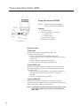
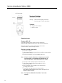
The problem is moisture
and contamination.
The solution is
SKF Brakemaster air dryers.
With the ongoing evolution of commercial vehicles,
the proliferation of new pneumatic powered
accessories has increased demands on vehicles’
compressed air systems. From kneeling buses to
multi-axle ABS brakes, new applications have raised
the requirements for clean, dry air, straining existing
technologies and creating a need for more efficient
and reliable air dryers.
The SKF Brakemaster family of air dryers is meeting
those needs.
In addition to units designed for conventional overthe-road applications, the SKF Brakemaster line
includes high performance air dryer units specifically
designed to handle the extreme air system demands
for such industries as transit and refuse.
From the light duty, maintenance saving Turbo-AC
to the state-of-the-art 2000 series air dryers now
featuring two styles of the Dual Turbo-2000 – the
standard Dual Turbo-2000 and the High Capacity
(H.C.) Dual Turbo-2000 – these heavy duty air dryers
allow fleets to match air dryer performance to specific
application requirements.
This manual provides a detailed technical overview
of the SKF Brakemaster line including SKF’s Filtration
Plus option, which can be retrofitted to the Turbo and
HD-2000 air dryers already in service for optimal
filtration performance. And with the addition of the
H.C. Dual Turbo-2000, the SKF Brakemaster line
now can meet the requirements of high output
compressors on 2010 and later model transit bus
engines. See the table on the back cover to determine
which air dryer is best suited to your application.
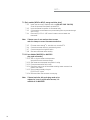
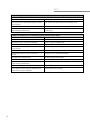
Table of contents
Section 1—dryer highlights and specifications.........4
H.C. Dual Turbo-2000...................................................... 68
Turbo-2000.................................................................................. 4
HD-2000....................................................................................... 6
Dual Turbo-2000 / H.C. Dual Turbo-2000............................. 8
Turbo-3000................................................................................12
Turbo-AC......................................................................................14
Turbo-2000 Filtration Plus Option.........................................16
Safety precautions / mounting guidelines.............................17
Turbo-3000.......................................................................... 84
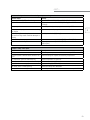
Section 2—recommended service
Turbo-2000...................................................................... 18
Parts list.......................................................................................18
Service schematic......................................................................19
Normal operation / flow diagram...........................................20
Trouble-shooting........................................................................21
Service procedures....................................................................24
HD-2000............................................................................... 34
Parts list.......................................................................................34
Service schematic......................................................................35
Normal operation / flow diagram...........................................36
Trouble-shooting........................................................................37
Service procedures....................................................................39
Dual Turbo-2000................................................................ 48
Parts list.......................................................................................48
Service schematic......................................................................49
Normal operation / flow diagram...........................................50
Trouble-shooting........................................................................51
Service procedures....................................................................55
Parts list.......................................................................................68
Service schematic......................................................................69
Normal operation / flow diagram...........................................70
Trouble-shooting........................................................................71
Service procedures....................................................................74
Parts list.......................................................................................84
Service schematic......................................................................85
Normal operation / flow diagram...........................................86
Trouble-shooting........................................................................87
Service procedures....................................................................90
Turbo-AC............................................................................... 98
Parts list.......................................................................................98
Service schematic......................................................................99
Normal operation / flow diagram........................................ 100
Trouble-shooting..................................................................... 101
Service procedures................................................................. 103
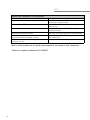
Original Brakemaster service kit reference chart.............. 110
Section 3—miscellaneous............................................111
Bench test procedures........................................................... 111
Socket reference...................................................................... 115
Tech Tips................................................................................... 116
Installation instructions.......................................................... 125
Parts listing.............................................................................. 138
Warranty................................................................................... 141
Vocational matrix........................................................ Back cover
3
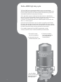
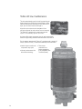
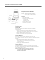
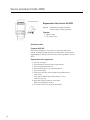
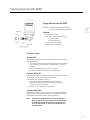
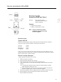
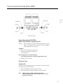
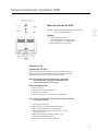
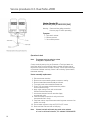
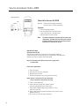
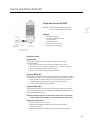
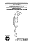
Turbo-2000 high duty cycle
The Turbo-2000 is the recommended choice for severe service applications,
where the compressor output reaches 30 CFM and duty cycles run as high as 40%!
Its ratio of large purge volume to desiccant produces the ideal filtering system and
contamination protection for heavy duty service today.
A four-way filtration system, consisting of three filter screens, a unique filtering
bag, plus four pounds of high quality molecular sieve desiccant, strips away moisture
and traps compressor blow-by. The spin-off cartridge can be serviced
in minutes. The compact purge tank can be installed anywhere and provides a full
460 cu. in. of clean purge air.
Improve the overall performance of your air system by upgrading to the Filtration
Plus option. Not only does this option reduce overall operating costs of the air dryer
by extending the cartridge service life, but it also optimizes the air systems efficiency
by reducing compressor burden caused by downstream contaminants.*
For all-weather operation the Turbo-2000 is equipped with a sealed
12 Volt (or optional 24 Volt) 75 watt thermostatically controlled heater.
• The choice for severe
stop-and-go operations
• Large purge volume for
extended compressor cycles
* Use HD-2000 for
naturally aspirated and
discharge line unload
(DLU) applications.
4
4
• Turbo boost protected
for all engine applications
(Fully compatible with
Cummins/Holset)
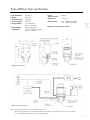
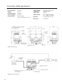
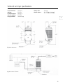
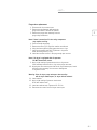
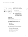
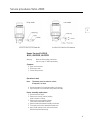
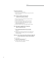
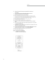
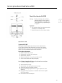
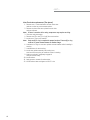
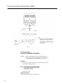
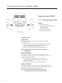
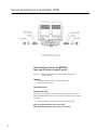
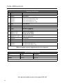
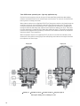
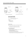
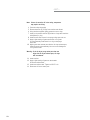
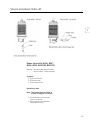
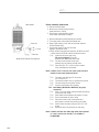
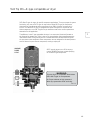
Turbo-2000 air dryer specifications
• Unit dimensions:
(see Fig. 1)
• Weight:
19.5 Lbs.
• Connection ports:
(see Fig. 2)
• Air flow capacity:
30 SCFM
• Drying medium:4 Lbs. desiccant
(spin-on cartridge)
• Drying medium External purge tank
regeneration:
(12" X 7" Dia. Wgt. = 10 Lbs.,
Volume = 460 Cu. In.)
• Turbo
protection valve: • Safety valve:
• Heater options:
Internal
175 psig
12V 75 Watt (6.6 Amps)
24V 75 Watt (3.2 Amps)
1
* Optional 2-stage filtration system
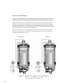
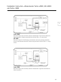
Fig. 1 Unit dimensions
Fig. 2 Connection schematic
Note: Mount purge tank higher than purge tank port on air dryer.
Use the purge tank port that is in the lowest position so that moisture can run down into the air dryer for expulsion.
If it is not possible install a petcock for periodic manual draining.
5
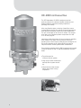
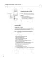
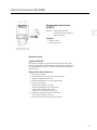
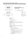
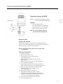
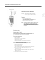
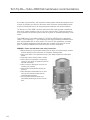
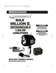
HD-2000 continuous flow
The SKF Brakemaster HD-2000 is designed to provide
optimum protection for naturally aspirated compressors and
systems employing continuous pumping compressors
(Discharge Line Unload).
A four-way filtration system, consisting of three filter screens,
a unique filtering bag, plus four pounds of high quality molecular
sieve desiccant, strips away moisture and traps contamination.
The spin-off cartridge can be serviced in minutes. The compact
purge tank can be installed anywhere and provides a full 460
cu. in. of clean purge air.
Improve the overall performance of your air system by upgrading
to the Filtration Plus option. Not only does this reduce the
operating costs of the air dryer by extending the cartridge service
life, but also optimizes the air system efficiency by reducing
compressor burden caused by downstream contaminants.
For all-weather operation the HD-2000 is equipped with a sealed
12 Volt (or optional 24 Volt) 75 watt thermostatically controlled
heater.
• Top performance for
continuous flow air systems
• Large purge volume and desiccant
bed keep the air system clean &
dry
• Unique internal pump-through
design means cooler running
compressors
6
6
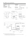
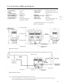
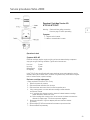
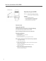
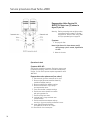
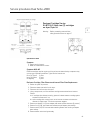
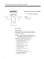
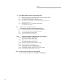
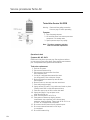
HD-2000 air dryer specifications
• Unit dimensions:
(see Fig. 1)
• Weight:
19.5 Lbs.
• Connection ports:
(see Fig. 2)
• Air flow capacity:
30 SCFM
• Drying medium:4 Lbs. desiccant
(Spin-on cartridge)
• Drying medium
regeneration:
External purge tank (12" X 7" Dia
Wgt. = 10 Lbs., Volume = 460 Cu.
In.)
• Safety valve:
175 psig
• Heater options:
12V 75 Watt (6.6 Amps)
24V 75 Watt (3.2 Amps)
* Optional 2-stage filtration system
Fig. 1 Unit dimensions
Fig. 2 Connection schematic
Note: Mount purge tank higher than purge tank port on air dryer.
Use the purge tank port that is in the lowest position so that moisture can run down into the air dryer for expulsion.
If it is not possible install a petcock for periodic manual draining.
7
1
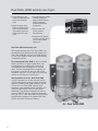
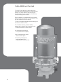
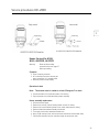
Dual Turbo-2000 extreme use dryers
• Proven effective by the
country’s largest and most
severe-use municipal
fleets.
• Keeps air system clean,
keeps air capacity high—
even in the most severe
use situations requiring
100% compressor duty
cycles.
• Integrated filtration system
removes compressor
blow-by before entering
desiccant cartridge protects downstream
components.
• Easy to install and
service; reduces
fleet downtime.
• Designed to be effective
in service use applications
such as transit refuse,
logging, etc.
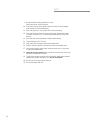
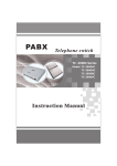
Dual Turbo-2000 extreme duty cycle
SKF now has two styles of the Dual Turbo-2000 – the
standard Dual Turbo-2000 and the High Capacity (H.C.)
Dual-Turbo-2000. Both the Dual Turbo-2000 and the
H.C Dual Turbo-2000 can meet the increased demands
of tomorrow’s vehicles.
The standard Dual Turbo-2000 has been a successful
solutions provider for all types of applications, such
as articulated buses, kneeling buses, as well as off
road applications that use all types of air-actuated
valves. The Dual Turbo-2000 offers a compressor air
flow output of up to 40 CFM and up to 100 percent
compressor duty cycle. The unit requires no purge tank
and has an internal timer to control cycles.
With the addition of the H.C. Dual Turbo-2000,
the SKF Brakemaster line of dual air dryers now can
meet the requirements of the high output compressors
required on 2010 and later model transit bus engines.
The new H.C. Dual Turbo-2000 is ideal for large
compressor output applications and is available in 12V
75W (6.6 amps) and 24V 75W (3.2 amps) options.
Additionally, it can withstand compressor air flow out
put of up to 80 CFM and up to 40 percent compressor
duty cycle. The H.C. Dual Turbo-2000 includes the same
internal filtration package as the standard Dual Turbo2000 air dryer with 99.9 percent efficiency.
H.C. Dual Turbo-2000
8
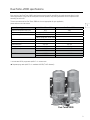
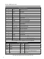
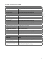
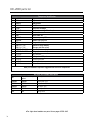
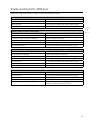
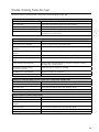
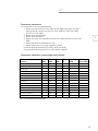
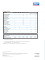
Dual Turbo-2000 specifications
Each version of the Dual Turbo-2000 is designed to meet the specific and difficult air quality demands found in high
volume applications. Large inlet and outlet ports minimize pressure drop, easing the burden on the compressor and
extending its service life.
To learn more about which Dual Turbo-2000 unit is more appropriate for your application,
please reference the chart below:
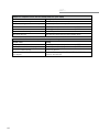
Operating parameters
Maximum compressor duty cycle
Maximum compressor size
Purge tank requirement
1
H.C. Dual Turbo-2000
Dual Turbo-2000
40%
100%
80 CFM
40 CFM
600 cu. in. required p
None
2 #221 purge tank can be used
D2 Governer controlled
Yes
No – internal timer
Turbo-boost compatible
Yes
Yes
Inlet/Outlet ports
3/4" npt
3/4" npt
Filtration package
6 internal filters per side
6 internal filters per side
#620984
#620920
24 V 75 Watt
#620986*
12 V 75 Watt
#620982
#620910
#620980*
* Includes two #221 purge tanks @460 Cu. In. volume each.
p Separate purge tank @690 Cu. In. available 619228 (7"x18" diameter)
Dual Turbo-2000
9
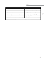
Dual Turbo-2000 specifications
• Unit dimensions:
• Weight:
• Connection ports:
• Air flow capacity:
• Drying medium:
(see Fig. 1)
47 Lbs.
(see Fig. 2)
40 CFM
8 Lbs. desiccant
(Spin-on cartridges, 2 @ 4 lb.)
Fig. 1 Unit dimensions
Fig. 2 Connection schematic
10
• Drying medium regeneration:
• Safety valve:
• Heater options:
• Filtration:
• Duty cycle:
System purge (controlled
alternating cycle)
200 psig
12V 75 Watt (6.6 Amps)
24V 75 Watt (3.2 Amps)
6 internal filters per side
Up to 100%
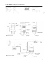
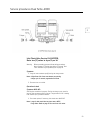
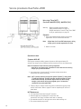
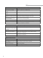
H.C. Dual Turbo-2000 specifications
• Unit dimensions: (see Fig. 1)
• Weight: 47 Lbs.
• Connection ports: (see Fig. 2)
• Air inlet temperature: 160º F (Max)
• Air flow capacity: 80 CFM
• Duty cycle capacity: up to 40%
• Drying medium: 8 Lbs. dessicant (spin-on
cartridges, 2 @ 4Lbs.)
• Drying medium Dedicated external purge regeneration: tank, minimum volume = 600 Cu. In.*
• Filtration:
6 internal filters
• Turbo protection valve: Internal
• Safety valve: 200 psig
• Heater options: 12V 75 watt (6.6 amps), 24V
75 watt (3.2 amps)
* Use #619228 with 690 Cu. In. or 2 #221 with
460 Cu. In. volume/each.
Fig. 1 Unit dimensions
Fig. 2 Connection schematic
Note: Mount purge tank(s) higher than purge tank port on air dryer.
Use the purge tank port that is in the lowest position so that moisture can run down into the air dryer for expulsion.
If it is not possible install a petcock for periodic manual draining.
11
1
Turbo-3000 over the road
The unique Turbo-3000 uses a highly efficient new
formula to match compressed air to a compact desiccant
package. This precise match of desiccant and purge
volume reduces both size and weight, while effectively
cleaning and drying the air system.
Ease of installation is an added benefit of this compact
design. It makes retro-fitting a one-step operation. Ports
are easily accessible and clearly marked.
The spin-on cartridge holds both desiccant and purge air
and can be serviced in minutes.
For all-weather operation, the Turbo-3000 is
equipped with a sealed 12 Volt (or optional 24 Volt)
75 watt thermostatically controlled heater.
• A compact streamlined design
for top performance on highway
• Self-contained purge air doesn’t
steal from brake system
• Turbo boost protected for all
engine applications (Fully
compatible with Cummins/Holset)
12
12
Turbo-3000 air dryer specifications
• Unit dimensions:
(see Fig. 1)
• Weight:
17.5 Lbs.
• Connection ports:
(see Fig. 2)
• Air flow capacity:
15 SCFM
• Drying medium:2 Lbs. desiccant
(Spin-on cartridge)
• Drying medium regeneration:
• Safety valve:
• Heater options:
Integral purge volume
175 psig
12V 75 Watt (6.6 Amps)
24V 75 Watt (3.2 Amps)
1
Fig. 1 Unit dimensions
Fig. 2 Connection schematic
13
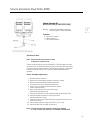
Turbo-AC low maintenance
This time tested design pays for itself by protecting the
brake system from moisture and contamination, while
reducing maintenance practically to zero. With this air
dryer, you can often install it and forget it.
A popular choice where there’s adequate air flow
over the surface of the unit to allow it to cool properly.
The Turbo-AC is designed for compressor output of
up to 15 CFM and duty cycles of up to 20%.
An internal filter traps compressor blow-by and contaminants,
while the large cooling chamber extracts moisture from the air.
For all-weather operation the Turbo-AC is equipped with a sealed 12
Volt (or optional 24 Volt) 75 watt thermostatically controlled heater.
• Ideal for light to medium air
compressor duty cycles
• Virtually maintenance-free
aftercooler technology
14
14
• Turbo boost
protected for all
engine applications
(Fully compatible with
Cummins/Holset)
Turbo-AC air dryer specifications
• Unit dimensions:
• Weight:
• Connection ports:
• Air flow capacity:
• Drying medium:
(see Fig. 1)
19.5 Lbs.
(see Fig. 2)
15 SCFM
Heat exchange
• Safety valve:
• Heater options:
175 psig
12V 75 Watt (6.6 Amps)
24V 75 Watt (3.2 Amps)
1
Fig. 1 Unit dimensions
Fig. 2 Connection schematic
15
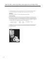
Turbo-2000
Filtration Plus option
New from SKF, the leader in
high performance air dryers
with the Filtration Plus Option
The best just got better! Introducing SKF’s new
Filtration Plus Option for Turbo-2000
and HD-2000. As more components draw on
the vehicle’s compressed air system, air quality
has become critical. A contaminated air system
dramatically adds unwanted operating costs
that the new Filtration Plus Option can avoid.
SKF’s Turbo-2000 series of air dryers,
including the HD-2000 and Dual Turbo-2000,
have led the field in it’s filtration system.
The new H.C. Dual Turbo-2000 also comes
standard with the Filtration Plus Option.
Now, we have stepped it up a notch with the
Filtration Plus cartridge, #T224-P.
The Filtration Plus Option provides the same
benefits as the current SKF series of air dryers
but adds an additional 2-stage high efficiency
filter that removes even the finest oil residue.
The Filtration Plus Option specifically addresses
high air volume applications, such as transit,
refuse or cement mixers.
Compressors with excessive oil
blow-by will also gain great benefit with the
Filtration Plus Option. The benefits of the air
dryers equipped with the Plus Option
are plentiful:
• Protection of down stream valving that gums
up with oil contamination.
• Improved air capacity. Compressor charge
times increase as oil and water filled wet
tanks reduce air capacity.
• Improved compressor service life. Coked up
discharge lines cause the compressor to work
harder shortening its service life.
• Extends air dryer cartridge service life.
The 2-stage filtration system added to the
already extensive cartridge filters extends the
service intervals.
• The 2-stage Filtration Plus Option is
self-cleaning with every purge cycle keeping
the performance optimized.
• Easily retrofits and upgrades the filtration
system of any existing SKF Turbo series
desiccant air dryer with a cartridge Plus kit
T224-P.
For more information visit us on our web site www.vsm.skf.com
16
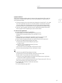
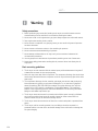
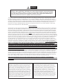
Safety precautions
1. Before performing any test and/or isolating the air dryer,
the vehicle’s wheels must be chocked making sure the vehicle
will not roll before releasing the brakes.
1
2. Never work under a unit supported only by a jack. Always
support the vehicle with stands.
3. Stop engine when working under a vehicle.
4. Never remove a component or a pipe plug unless you
are certain all system air pressure has been exhausted.
5. Never connect or disconnect a hose or line containing
air pressure.
6. Never exceed recommended working air pressure.
7. Never attempt to disassemble an air dryer until you have
read and understood all recommended procedures.
8. Use only proper tools and observe all precautions pertaining
to the use of those tools.
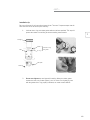
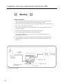
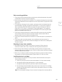
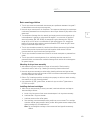
Basic mounting guidelines
1. The air dryer must be mounted with the exhaust ports
positioned downward.
2. Mount air dryer lower than the air compressor. The compressor
discharge line should slope continuously downward from the
compressor to the air dryer without any dips which cause
water traps.
3. The compressor discharge line size, material, and length must be
such that the dryer air inlet temperature is typically no more than
160 degrees F or no less than 45 degrees F above low ambient, (Ref.
SAE J2383). An example of a typical discharge line: Total line length
10 ft. to 12 ft. which is a combination of rigid copper (approx. 4 ft.
length) and balance of line length being stainless-steel braid sheathed
PTFE. Avoid using 90 degree elbow fittings.
4. The air dryer should be mounted in a location with sufficient space
around it to facilitate service and to provide visual access for periodic
inspection. Allow at least 2.00 inch clearance above air dryer for
desiccant cartridge service.
5. The air dryer should be mounted out of direct tire or wheel road
splash or protected from splash.
6. The air dryer, with its mounting bracket, lines, and fittings should be
mounted in a protected location such that minor mechanical damage
to the vehicle will not damage the air system integrity. Use mounting
bolts that are Grade 5 or higher.
17
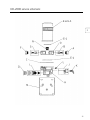
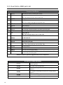
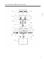
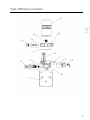
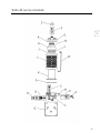
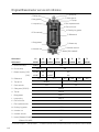
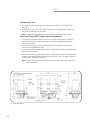
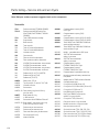
Turbo-2000 parts list
Component identification
A
B
C
D
E
E-1
F
G
H
H
I
J
J
K
L
M
N
O
Q
Q
619340
619360
610237
223
610077
610069
T224
T224-P
610236
238
619086
619112
619087
619113
235
248 12V 75W
249 24V 75W
619110 12V 75W
619111 24V 75W
619900
610024
228
619115
619140
619091
619093
Regeneration valve nut
Regeneration valve kit
Body gasket
Seal retainer
Desiccant cartridge
Desiccant cartridge filtration plus
Check valve nut
Check valve kit
Bottom cap assy 12V STD
Bottom cap assy 12V E-Type
Bottom cap assy 24V STD
Bottom cap assy 24V E-Type
Purge valve kit
Heater kit early model
(Orange and blue wires)
Heater kit late model
Plug style connection
Wire harness
Safety valve 175 psi
Turbo valve kit
Mounting bracket
Cartridge stud
Mid-section w/valves STD
Mid-section w/valves E-Type
619340
619360
Service kit contains T224, 228, 235, 238
Service kit contains T224-P, 228, 235, 238
Bold part numbers represent suggested stock service components
620604
Dryer part number description
STD-w/filtration plus option E-Type*
Description
620300
620500
Dryer/tank 12V
Dryer/tank 24V
620304
620504
620602
620606
620302
620306
STD
620600
620502
620506
620526
221
221
221
Air dryer 12V
Air dryer 24V
Air dryer 12V retrofit w/modified mounting
bracket to match T2000 hole pattern
Purge tank
*Holset SS E-Type or QE compressor compatible
For right-hand models see parts list on pages 139 & 140.
18
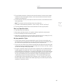
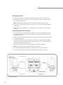
Turbo-2000 service schematic
2
19
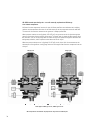
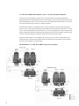
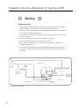
Turbo-2000 normal operation/cycles – use with Turbo boosted compressors
Air flows from the compressor into the air dryer. Air flows past filters and desiccant bed,
stripping moisture and contaminants from the air and exits dryer to the purge tank and to the
wet tank. The reservoir line from the wet tank to the governor is always pressurized.
When pressure reaches cut-out (typically 120-125 psi), the governor sends an air signal
through the governor line to the air dryer opening purge valve and closing turbo valve. The
check valve is closed via back pressure from the wet tank. Then, air in the purge tank re-enters
the dryer and passes through the desiccant bed taking away moisture, and is expelled out the
bottom of the air dryer. Turbo boost from the compressor is checked at inlet of the dryer with
closed turbo valve. E-Type dryers provide back pressure to the compressor during stand-by. This
feature is not intended for use for any compressor other than Holset E-Type compressors.
When the pressure drops to cut-in (typically 90-95 psi), the air in the UNL line evacuates out
the exhaust port of the governor closing purge valve and opening turbo valve and once again
flows from the compressor into the air dryer.
Charge cycle
Clean/dry air
Atmospheric pressure
Purge cycle
Dirty/wet charged air
Dirty/wet purged air
Note: Approx. 95PSI gov cut in, 120PSI gov cut out
20
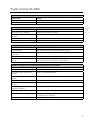
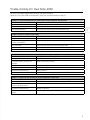
Trouble-shooting Turbo-2000
Review Turbo-2000 normal operation / cycles prior to trouble-shooting
Problem: air continually leaks from the exhaust port during compressor standby mode
Possible cause
Remedy
Worn check valve
Clean cavity and replace check valve assembly #238
Worn turbo valve
Clean cavity and replace turbo valve assembly #228
Worn purge valve seal
Clean cavity and replace purge valve assembly #235
2
Problem: system air pressure drops rapidly
Possible cause
Remedy
Fittings are loose or damaged
Tighten and/or replace as necessary
Air reservoir, tubing,
or hoses are damaged
Repair or replace as necessary
Worn check valve
Clean cavity and replace check valve assembly #238
Worn turbo valve
Clean cavity and replace turbo valve assembly #228
Worn purge valve seal
Clean cavity and replace purge valve assembly #235
Problem: air compressor moves into the standby mode but cycles rapidly
Possible cause
Remedy
Fittings are loose or damaged
Tighten and/or replace as necessary
Air reservoir, tubing, or hoses are
damaged
Repair or replace as necessary
Worn check valve
Clean cavity and replace check valve assembly #238
Worn turbo valve
Clean cavity and replace turbo valve assembly #228
D2 governor malfunctioning
Replace governor
Worn purge valve seal
Clean cavity and replace purge valve assembly #235
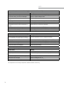
Problem: air leaks from the exhaust port during compressor charge mode
Possible cause
Remedy
Worn purge valve
Clean cavities and replace purge valve assembly #235
Dirt/foreign material
is stuck in the purge valve
Clean cavity and replace valve assembly #235
D2 governor malfunctioning
Replace D2 governor
Heater assembly malfunctioning (>32
degrees)
Replace heater assembly #246(12V), 247(24V),
248(12V, 249(24V), 619110(12V) or 619111(24V)
21
con’t...
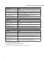
Problem: air compressor runs continuously (system pressure will not build)
Possible cause
Remedy
Fittings are loose or damaged
Tighten or replace loose or damaged fittings
Air reservoir, tubing, or hoses are damaged
Repair or replace damaged items
The air compressor needs to be serviced or
replaced
Rebuild or replace the air compressor
Worn purge valve
Clean cavity and replace the purge valve assembly #235
The air compressor capacity is too low for vehicle
Install larger air compressor
Line between governor and air compressor is
blocked
Replace the line or remove the blockage
The safety valve is malfunctioning
Replace the safety valve #610024
Ice has formed in the purge valve
Replace heater assembly #246(12V), 247(24V), 248(12V),
249(24V), 619110(12V) or 619111(24V)
D2 governor malfunctioning
Replace D2 governor
Problem: air dryer does not exhaust during compressor standby mode
Possible cause
Remedy
The line between the air governor and the air
dryer control port is missing, leaking, or damaged
Install or replace the air line, or tighten the fittings
Worn purge valve
Clean cavity and replace purge valve assembly #235
Ice has formed in the purge valve
Replace heater assembly #246(12V), 247(24V),
248(12V), 249(24V), 619110(12V) or 619111(24V)
Heater is malfunctioning
Replace heater assembly #246(12V), 247(24V),
248(12V), 249(24V), 619110(12V) or 619111(24V)
Purge valve sleeve is misaligned
Align purge valve sleeve
Problem: safety valve opens
Possible cause
Remedy
Air dryer check valve is blocked
Clean cavity and replace check valve assembly #238
Air brake system is blocked down stream of air
dryer
Remove blockage or replace the necessary components
Air compressor governor malfunctioning
Replace compressor D2 governor
Blocked desiccant cartridge
Replace cartridge #T224 and upgrade to filtration plus option
T224-P*
The safety valve is malfunctioning
Replace the safety valve #610024
*Air compressor service may be required to address excessive oil blow-by.
22
con’t...
Problem: water accumulation in air system (tanks)
Possible cause
Remedy
Desiccant is contaminated
Replace desiccant cartridge #T224 or upgrade to T224-P for optimal
filtration performance
The air compressor capacity is too low for
vehicle
Install larger air compressor and replace desiccant cartridge #T224
Malfunctioning regeneration valve
Clean cavity and replace regeneration valve
assembly #223
The line between the purge tank and the
air dryer control port is missing, leaking, or
damaged
Install or replace the air line, or tighten the fittings
Line between the compressor and air dryer
too short
Fit new line with a minimum length of 6 feet copper line or (insufficient
pre-cool) 12 feet of steel braided Teflon ®*
2
Refer to vehicle manufacturer for specific test
procedures for non related air dryer components.
* Teflon
®
is a registered trademark of E.I. DuPont.
23
Service procedures Turbo-2000
Purge Valve Service Kit #235
Warning:Read and follow safety precautions
found on page 17 before proceeding
Symptom
1. Dryer won’t exhaust
2. Air leak at exhaust port during the:
a) Charge mode
b) Stand-by mode
3. Pressure slow or no build
4. Compressor cycles rapidly
Operational check
Symptom #1:
Start engine and build to cutout pressure. If dryer does not exhaust
proceed as follows:
1.Check for air pressure in line connecting D2 governor to control
port of air dryer. If no pressure is present in line, service D2 governor.
2. Check for blockage at exhaust port of air dryer.
3. If items 1 and 2 are OK, replace purge valve #235.
Symptom #2A & #3:
Start engine and build air pressure. During the charge cycle, check
for air leaking at exhaust port of dryer. If air is leaking from exhaust port proceed
as follows:
1.No air pressure should be present in line connecting D2
governor and dryer purge valve during charge cycle. If there
is, service D2 governor.
2. If item 1 is OK, replace purge valve #235
Symptom #2B & #4:
Start engine and build to cut out pressure. Stop engine. Allow one minute
for purge air to discharge dryer. If air continues to discharge from exhaust port
of dryer, replace purge valve #235.
Note: Air discharge could also be due to worn check valve
or turbo valve. Refer to pages 27 and 28 for service
procedures on these valves.
24
con’t...
Purge valve replacement
1. Disconnect air line at control port.
2.Remove the two fasteners that attach the
purge valve retainer. Remove the retainer.
3.Remove the purge valve assembly from the
purge cavity and discard.
2
Note: If there is excessive oil in the cavity, compressor
may require servicing.
4. Clean the cavity thoroughly.
5. Remove the three (3) o-rings from retainer and discard.
6. Using lubricant supplied, lightly grease the new o-rings.
7.Install on the retainer the two- (2) thickest o-rings then
install the third (thinner) o-ring.
8.Install the new filter screen in the purge cavity open end out.
Note: If air dryer is equipped with oil separator
DO NOT install filter screen.
9.Apply a light coating of grease around the o-ring seat on
valve assembly. Install the thin o-ring on the purge valve seat.
10.Aligning the valve exhaust port with the air dryer exhaust port, install
the purge valve assembly. Use care not to dislodge the
o-ring from its seat.
Warning: If the air dryer purge valve port does not align
with air dryer exhaust port, air dryer will not exhaust!
11. Install retainer.
12.Apply a light coating of grease on the threads
of the two retainer bolts.
13.Install two retainer bolts. Tighten to 10-15 ft. lb.
14. Reconnect the control line to air dryer control port.
25
Service procedures Turbo-2000
Regeneration Valve Service Kit #223
Warning:Read and follow safety precautions
found on page 17 before proceeding
Symptom
1. Water in tanks.
2. No purge air flow.
Operational check
Symptom #1 & #2:
Start engine and build to cut-out pressure. Stop engine. After initial
exhaust, air should flow with decreasing intensity out the exhaust port for
approximately 45 seconds. If air fails to flow, replace regeneration valve kit
#223.
Regeneration valve replacement
1. Drain the air system.
2. Disconnect the air line at air dryer purge tank port.
3. Remove regeneration valve nut.
4. Remove and discard o-ring, spring and spindle.
5. Clean nut and cavity.
6.Position new spindle in the cavity with spring pocket side out.
Install spring.
7.Using grease supplied, apply a light coating on o-ring.
Install o-ring on nut.
8.Apply light coating of grease on nut threads.
Install nut and tighten to 60 ft. lb.
9. Re-connect air line to air dryer purge tank port.
26
Service procedures Turbo-2000
Check Valve Service Kit #238
Warning:Read and follow safety precautions
found on page 17 before proceeding
2
Symptom
1. Dryer frequently exhausts.
2.Air continually flows from exhaust port
when compressor is in standby mode.
3. Wet tank pressure drops rapidly.
Note:The above symptoms could also
lead to turbo valve replacement.
A malfunctioning turbo valve will
tend to allow pressure to drop to
cut-in pressure within seconds on
E-Type dryers.
Operational check
Symptom #1, #2, & #3:
Start engine and build to cut out pressure. Stop engine. Allow one
minute for purge air to discharge dryer. If air continues to discharge
from exhaust port of dryer, replace check valve #238.
Note: Air discharge could also be due to worn purge valve
or check valve.
Turbo valve replacement
1. Drain air system.
2. Disconnect air line from outlet port.
3. Remove check valve nut.
4. Remove and discard o-ring, spring, spindle, and ball.
Note: If there is excessive oil in the check valve cavity, compressor
may require servicing.
5. Clean nut and cavity area.
6.Install new ball in cavity. Next, position spindle
with spring pocket facing out. Install spring.
7.Using grease supplied, apply a light coating on o-ring.
Install o-ring on nut.
8.Apply a light coating of grease to threads of nut.
Install nut and tighten to 60 ft. lb.
9. Re-connect air line to air dryer outlet port.
27
Service procedures Turbo-2000
Turbo Valve Service Kit #228
Warning:Read and follow safety precautions
found on page 17 before proceeding
Symptom
1. Dryer frequently exhausts.
2.Air continually flows from exhaust port
when compressor is in standby mode.
3. System pressure drops very rapidly.
Note:The above symptoms could also
lead to Check valve replacement.
Operational check
Symptom #1, #2, & #3:
Start engine and build to cut out pressure. Stop engine. Allow one
minute for purge air to discharge dryer. If air continues to discharge
from exhaust port of dryer, replace turbo valve #228.
Note: Air discharge could also be due to worn purge valve
or check valve.
Turbo valve replacement
1. Drain the air system.
2. Disconnect the heater wiring.
3.Disconnect the inlet and control lines
from their respective ports.
4.Remove 8 bolts from bottom cap and
set aside. Discard gasket.
5. Remove turbo nut, valve stop and valve and discard.
6. Clean cavity area thoroughly.
7.Lightly coat the 2 (small) o-ring surfaces and install on piston.
Carefully install valve in cavity with tapered side up.
8. Place valve stop on top of valve concave side down.
9.Lightly lube (large) o-ring and place on nut.
Install flat seal into nut.
10. Install nut and tighten to 40-45 ft. lb.
11.Place gasket on bottom cap aligning all holes. Locate bottom cap
so that inlet port is directly below outlet port. Install the 8 bolts.
Tighten bolts to 20-25 ft. lb. or 25-30 ft. lb. if equipped with oil
separator.
12. Re-connect inlet and control lines to their respective ports.
13. Re-connect heater wiring.
28
Service procedures Turbo-2000
Dessicant Cartridge Service Kit
#T224 & #T224-P
2
Warning:Read and follow safety precautions
found on page 17 before proceeding
Symptom
1. Regular service interval.
2. Water or contamination in tanks.
Operational check
Symptom #1 & #2
Desiccant cartridge requires regular servicing at intervals determined by compressor
duty cycle or type of driving conditions. Typical service intervals are:
Line haul
Inner city
Refuse/transit
Off highway
3 years
2 years
1 year
1 year
Using T224-P with extra filtration will protect desiccant longer and lengthening service
intervals. Add 1 year to above chart. The above is a guideline only. Drain tanks on regular
basis. If moisture exists, replace cartridge.
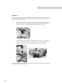
Desiccant cartridge replacement
* Steps required for service kit T224-P only.
1. Relieve all system air pressure.
2. *Disconnect heater lead wire from air dryer.
3. *Disconnect inlet and control lines from their respective ports.
4. Using a strap wrench, turn the desiccant cartridge counterclockwise
and remove. Discard.
4a. If cartridge spins without loosening, place a thin blade between cartridge gasket and base to break seal. If not,
4b. strike cartridge with a center punch or ball nose at the lower end where the diameter is slightly larger. This binds components together.
5. Remove and discard o-ring from adapter plate stud and filter element
(if present).
6. *Remove eight (8) 3/8" hex head bolts from bottom cap and set aside.
7. * Remove bottom cap assembly.
29
con’t...
8. *Remove filter plate (if present) and gasket(s) from bottom cap and discard.
9. *Clean bottom cap sump cavity, gasket surface and inside of adapter plate
castings of oil and contaminants.
10. *Service of turbo valve is recommended at this time also. Refer to service
procedures on page 25.
11. *Place new gasket on bottom cap bolt flange.
12. *Place new filter plate into bottom cap cavity. Position filter plate cavity, as
shown in Fig. 1, with arrow pointed toward inlet port of bottom cap.
13. *Re-install bottom cap assembly to adapter plate casting.
14. *Torque (8) bolts to 25-50 ft. lbs.
15. Clean top surface of adapter plate and threaded stud.
16. *Position a new filter element around cartridge stud and onto adapter plate.
17. Using grease supplied, apply a light coating of grease onto o-ring.
Install o-ring onto threaded stud.
18. Important for easy removal: Apply a generous coat of grease on the new desiccant
cartridge gasket surface.
19. Thread new cartridge onto stud turning clockwise. When gasket
contacts adapter plate, tighten cartridge 1/2 turn. Do not overtighten!
20. *Re-connect airlines to air dryer inlet and control ports.
21. *Re-connect heater lead wire.
Note: Cartridge Stud Kit #619140 available if stud needs replacing.
30
Service procedures Turbo-2000
Early model
Late model
2
Heater Service Kit #248,
#249, #619110, #619111
Warning:Read and follow safety precautions
found on page 17 before proceeding.
Symptom
1. Dryer won’t exhausts
2. Exhaust port leak.
3. Cannot build pressure.
Operational check
Note:Thermostat must be cooled to at least
35 degrees F to check.
1. Closed ohmmeter circuit indicates heater is functioning.
2. Open ohmmeter circuit indicates faulty heater assembly.
Heater assembly replacement
1. Disconnect heater leads.
2.Remove set screw (if present) holding
heater element in casting.
3.Remove two screws attaching heater
cover and/or thermostat to casting.
4. Remove heater/thermostat assembly and discard.
5. Thoroughly clean entire heater/thermostat area.
6.Apply a light coating of anti-seize to the heater
element and thermostat cavity.
31
con’t...
7.Insert heater element into hole and twist slightly to spread anti-seize.
7.1Early Models (#248 or #249; orange and blue wires)
7..1.1Install new set screw (if required) until snug
(DO NOT OVER TIGHTEN) Screw will protrude
from bottom cap about 1/8”.
7..1.2Insert thermostat into position
in thermostat cavity.
7..1.3Coil lead wires around heater cover posts
allowing wires to protrude through slots in cover.
7..1.4Place two (2) 6-32 x 1-1/8 screws in heater
cover and attach the thermostat.
Note:If heater cover is not used, use short screws
and wire clamps to secure thermostat and wires.
7..1.5 Fill heater cover through 1/4” hole with
non-corrosive RTV.
7..1.6Connect blue heater wire to a good chassis ground.
7..1.7 Connect orange wire to ignition switch.
7..1.8Seal and route heater wires carefully.
7.2.11Late Models (#619110 or #619111); plug style connection
7.1.2.1.Slide o-ring over heater and thermostat
into position around connector flange.
7.1.2.2. Slide heater and thermostat into position in cavity.
7.1.2.3. Ensure thermostat sits flat in cavity.
7.1.2.4.Place foam cube on top of thermostat and
bring heater connector into position over heater.
7.1.2.5.Secure heater assembly using the
(2) 8-32 x 1/2” screws.
7.1.2.6. Reconnect Metri-Pak connector to male plug.
Note:If heater lead wire with male plug needs to be replaced or is not in vehicle
wire harness it is available in Kit #619900.
32
Turbo-2000 Notes:
2
33
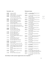
HD-2000 parts list
A
B
C
D
E
E-1
F
G
H
I
J
J
K
L
M
N
O
610237
223
610077
610110
T224
T224-P
610236
238
619089
619090
235
248 12V 75W
249 24V 75W
619110 12V 75W
619111 24V 75W
619900
610024
619115
619140
619091
Component identification
Regeneration valve nut
Regeneration valve kit
Body gasket
Seal retainer
Desiccant cartridge
Desiccant cartridge filtration plus
Check valve nut
Check valve kit
Bottom cap assy 12V
Bottom cap assy 24V
Purge valve kit
Heater kit early models
(Orange and blue wires)
Heater kit late models
(Plug style connection)
Wire harness
Safety valve 175 psi
Mounting bracket
Cartridge stud
Mid-section with valves
Bold part numbers represent suggested stock service components
620550
620554
620552
620556
Air dryer part number description
HD w/ filtration plus Description
option
620350
Dryer/tank 12V
620354
Dryer/tank 24V
620352
Air dryer 12V
620356
Air dryer 24V
221
221
HD
Purge tank
For right-hand models see parts list on pages 139 & 140.
34
HD-2000 service schematic
2
35
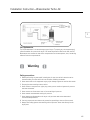
HD-2000 normal operation/cycles – use with naturally aspirated and Discharge
Line Unload compressors
Air flows from the compressor into the air dryer. Air flows past filters and desiccant bed, stripping
moisture and contaminants from the air and exits the dryer to the purge tank and to the wet tank.
The reservoir line from the wet tank to the governor is always pressurized.
When pressure reaches cut-out (typically 120-125 psi), the governor sends air signal through the
governor line to the air dryer opening purge valve. The check valve is closed via back pressure from
the wet tank. Then, air in the purge tank re-enters the dryer and passes through the desiccant bed
taking away moisture, and is expelled out the bottom of the air dryer.*
When the pressure drops to cut-in (typically 90-95 psi), the air in the UNL line evacuates out the
exhaust port of the governor closing purge valve and once again flows from the compressor into the
air dryer.
Charge cycle
Clean/dry air
Purge cycle
Atmospheric pressure
Dirty/wet charged air
Dirty/wet purged air
Note: Approx. 95PSI gov cut in, 120PSI gov cut out
*DLU compressors will continue to pump into air dryer and out exhaust port.
36
Trouble-shooting HD-2000
Review HD-2000 normal operation / cycles prior to trouble-shooting
Problem: air continually leaks from the exhaust port during compressor standby mode
Possible cause
Remedy
Worn check valve
Clean cavity and replace check valve assembly #238
Worn purge valve seal
Clean cavities and replace purge valve assembly #235
Problem: system air pressure drops rapidly
Possible cause
Remedy
Fittings are loose or damaged
Tighten and/or replace as necessary
Air reservoir, tubing, or hoses are
damaged
Repair or replace as necessary
Worn check valve
Clean cavity and replace check valve assembly #238
Worn purge valve seal
Clean cavities and replace purge valve assembly #235
2
Problem: air leaks from the exhaust port during compressor charge mode
Possible cause
Remedy
Worn purge valve
Clean cavities and replace the purge valve assembly #235
Dirt/foreign material is stuck in the
purge valve
Clean cavities and replace the purge valve assembly #235
D2 governor malfunctioning
Replace D2 governor
Heater assembly malfunctioning (>32
degrees)
Replace heater assembly #246(12V), 247(24V),
248(12V), 249(24V), 619110(12V) or 619111(24V)
Problem: air compressor runs continuously (system pressure will not build)
Possible cause
Remedy
Fittings are loose or damaged
Tighten or replace loose or damaged fittings
Air reservoir, tubing, or hoses are
damaged
Repair or replace damaged items
Air compressor needs to be serviced or
replaced
Rebuild or replace the air compressor
Worn purge valve
Clean cavities and replace the purge valve assembly #235
The air compressor capacity is too low
for vehicle
Install larger air compressor
Line between governor and air
compressor is blocked
Replace the line or remove the blockage
The safety valve is malfunctioning
Replace the safety valve #610024
Ice has formed in the purge valve
Replace heater assembly #246(12V), 247(24V), 248(12V), 249(24V),
619110(12V) or 619111(24V)
D2 governor malfunctioning
Replace D2 governor
37
con’t...
Problem: air dryer does not exhaust during compressor standby mode
Possible cause
Remedy
Line between the air governor and the
air dryer
Install or replace the air line, or control port is missing, leaking, or damaged.
Tighten the fittings.
Worn purge valve
Clean cavities and replace the purge valve assembly #235
Ice has formed in the purge valve
Replace heater assembly #246(12V), 247(24V), 248(12V), 249(24V),
619110(12V) or 619111(24V)
Heater is malfunctioning
Replace heater assembly #246(12V), 247(24V), 248(12V),
249(24V), 619110(12V) or 619111(24V)
Purge valve sleeve is misaligned
Align purge valve sleeve
Problem: safety valve opens
Possible cause
Remedy
Air dryer check valve is blocked
Clean cavity and replace the check valve assembly #238
Air brake system is blocked down
stream from the air dryer
Remove blockage or replace the necessary
components
Air compressor governor is
malfunctioning
Replace the compressor D2 governor
Blocked desiccant cartridge
Replace cartridge #T224 and upgrade to filtration plus T224-P**
The safety valve is malfunctioning
Replace the safety valve #610024
Problem: water accumulation in air system (tanks)
Possible cause
Remedy
Desiccant is contaminated
Replace desiccant cartridge #T224
Air compressor capacity is too low for
vehicle
Install larger air compressor and replace desiccant cartridge #T224
Malfunctioning regeneration valve
Clean cavity and replace regeneration valve assembly #223
Line between the purge tank and
the air dryer control port is missing,
leaking, or damaged
Install or replace the air line, or tighten the fittings
Line between the compressor and air
dryer too short line
Fit new line with a minimum length of 6 feet copper
(insufficient pre-cool) or 12 feet of steel braided Teflon ®.*
Refer to vehicle manufacturer for specific
test procedures for non-related air dryer components.
®
*Teflon is a registered trademark of E.I. DUPONT
**Air compressor service may be required to address excessive oil blow-by
38
Service procedures HD-2000
Purge Valve Service Kit #235
Warning:Read and follow safety precautions
found on page 17 before proceeding
2
Symptom
1. Dryer won’t exhaust.
2. Air leak at exhaust port during the:
a) Charge mode
b) Stand-by mode
3. Pressure slow or no build.
4. Compressor cycles rapidly.
Operational check
Symptom #1:
Start engine and build to cutout pressure. If dryer does not exhaust
proceed as follows:
1.Check for air pressure in line connecting D2 governor to control
port of air dryer. If no pressure is present in line, service D2
governor.
2. Check for blockage at exhaust port of air dryer.
3. If items 1 and 2 are OK, replace purge valve #235.
Symptom #2A & #3:
Start engine and build air pressure. During the charge cycle, check for
air leaking at exhaust port of dryer. If air is leaking
from exhaust port, proceed as follows:
1.No air pressure should be present in line connecting
D2 governor and dryer purge valve during charge cycle.
If there is, service D2 governor.
2. If item 1 is OK, replace purge valve #235
Symptom #2B & #4:
Start engine and build to cut out pressure. Stop engine. Allow one
minute for purge air to discharge dryer. If air continues to discharge
from exhaust port of dryer, replace purge valve #235.
Note:Air discharge could also be due to worn check valve.
Refer to page 42 for service procedure. On “Discharge
Line Unload” systems air will flow from exhaust port
of dryer when engine is running and compressor is in
stand-by mode.
39
con’t...
Purge valve replacement
1. Disconnect air line at control port.
2.Remove the two fasteners that attach the purge valve retainer.
Remove the retainer.
Note:If there is excessive oil in the cavity,
compressor may require servicing.
3. Remove the purge valve assembly from cavity and discard.
4. Clean the cavity thoroughly.
5. Remove the three (3) o-rings from retainer and discard.
6. Using lubricant supplied, lightly grease the new o-rings.
7.Install on the retainer the two- (2) thickest o-rings then
install the third (thinner) o-ring.
8. Install the new filter screen in the purge cavity open end out.
Note:If air dryer is equipped with oil separator
DO NOT install filter screen.
9.Apply a light coating of grease around the o-ring seat
on valve assembly. Install the thin o-ring on the purge
valve seat.
10.Aligning the valve exhaust port with the air dryer exhaust port,
install the purge valve assembly. Use care not to dislodge the
o-ring from its seat.
Warning:If the air dryer purge valve port does not align with
air dryer exhaust port, air dryer will not exhaust!
11. Install retainer.
12.Apply a light coating of grease on the
threads of the two retainer bolts.
13.Install two retainer bolts. Tighten to 10-15ft.lb.
Re-connect air line to control port.
40
Service procedures HD-2000
Regeneration Valve Service
Kit #223
Warning:Read and follow safety
precautions found on page 17
before proceeding
2
Symptom
1. Water in tanks.
2. No purge air flow.
Operational check
Symptom #1 & #2:
Start engine and build to cut-out pressure. Stop engine. After initial
exhaust, air should flow with decreasing intensity out the exhaust port
for approximately 45 seconds. If air fails to flow, replace regeneration
valve kit #223.
Regeneration valve replacement
1. Drain the air system.
2. Disconnect the air line at air dryer purge tank port.
3. Remove regeneration valve nut.
4. Remove and discard o-ring, spring and spindle.
5. Clean nut and cavity.
6.Position new spindle in the cavity
with spring pocket side out. Install spring.
7.Using grease supplied, apply a light
coating on o-ring. Install o-ring on nut.
8.Apply light coating of grease on nut threads.
Install nut and tighten to 60 ft. lb.
9. Re-connect air line to air dryer purge tank port.
41
Service procedures HD-2000
Check Valve Service Kit #238
Warning:Read and follow safety precautions
found on page 17 before proceeding
Symptom
1. Dryer frequently exhausts.
2.Air continually flows from exhaust port
when compressor is in standby mode.
3. Wet tank pressure drops rapidly.
Operational check
Symptom #1, #2, & #3:
Start engine and build to cut out pressure. Stop engine. Allow one
minute for purge air to discharge dryer. If air continues to discharge
from exhaust port of dryer, replace check valve #238.
Note: Air discharge could also be due to worn purge valve.
Check valve replacement
1. Drain air system.
2. Disconnect air line from outlet port.
3. Remove check valve nut.
4. Remove and discard o-ring, spring, spindle, and ball.
Note:If there is excessive oil in the check valve cavity, compressor
may require servicing.
5. Clean nut and cavity area.
6.Install new ball in cavity. Next, position spindle with spring pocket
facing out. Install spring.
7.Using grease supplied, apply a light coating on o-ring.
Install o-ring on nut.
8.Apply a light coating of grease to threads of nut.
Reinstall nut and tighten to 60 ft. lb. Re-connect
air line to air dryer outlet port.
42
Service procedures HD-2000
Dessicant Cartridge
Service Kit #T224 & # T224-P
Warning:Read and follow safety
precautions found on page 17
before proceeding
2
Symptom
1. Regular service interval.
2.Water or contamination in tanks.
Note: If there is excessive oil present,
compressor may require servicing
to T224-P upgrade.
Operational check
Symptom #1 & #2
Desiccant cartridge requires regular servicing at intervals determined by compressor
duty cycle or type of driving conditions. Typical service intervals are:
Line haul
Inner city
Refuse/transit
Off highway
3 years
2 years
1 year
1 year
Using T224-P with extra filtration will protect desiccant longer and lengthening service
intervals. Add 1 year to above chart. The above is a guideline only. Drain tanks on regular
basis. If moisture exists, replace cartridge.
Desiccant cartridge replacement
* Steps required for service kit T224-P only.
1. Relieve all system air pressure.
2. * Disconnect heater lead wire from air dryer.
3. *Disconnect inlet and control lines from their respective ports.
4.Using a strap wrench, turn the desiccant cartridge counterclockwise and remove.
Discard.
4a. If cartridge spins without loosening, place a thin blade between cartridge gasket and base to break seal. If not,
4b. strike cartridge with a center punch or ball nose at the lower end where the diameter is slightly larger. This binds components together.
5.Remove and discard o-ring from adapter plate stud and filter element (if present).
6. *Remove eight (8) 3/8" hex head bolts from bottom cap and set aside.
7. * Remove bottom cap assembly.
43
con’t...
8. *Remove filter plate (if present) and gasket(s) from bottom cap
and discard.
9. *Clean bottom cap sump cavity, gasket surface and inside of
adapter plate castings of oil and contaminants.
10. *Place new gasket on bottom cap bolt flange.
11. *Place new filter plate into bottom cavity. Position filter plate in cavity,
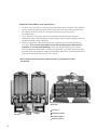
as shown in Fig. 1, with arrow pointed toward inlet port of bottom cap.
12. *Re-install bottom cap assembly to adapter plate casting.
13. *Torque (8) bolts to 25-30 ft. lbs.
14. Clean top surface of adapter plate and threaded stud.
15. *Position a new filter element around cartridge stud and onto adapter
plate.
16. Using grease supplied, apply a light coating of grease onto o-ring. Install
o-ring onto threaded stud.
17. Important for easy removal: Apply a generous coat of grease on the new
desiccant cartridge gasket surface.
18. Thread new cartridge onto stud turning clockwise. When gasket contacts
adapter plate, tighten cartridge 1/2 turn. Do not overtighten.
19. *Re-connect airlines to air dryer inlet and control ports.
20. *Re-connect heater lead wire.
Note:Cartridge Stud Kit #619140
available if stud needs replacing.
44
Service procedures HD-2000
Early model
Late model
2
Heater Service Kits #248,
#249, #619110, #619111
Warning:Read and follow safety
precautions found on page 17
before proceeding.
Symptom
1. Dryer frequently exhausts.
2.Air continually flows from exhaust port
when compressor is in standby mode.
3. Wet tank pressure drops rapidly.
Operational check
Note: Thermostat must be cooled to at least 35 degrees F to check.
1. Closed ohmmeter circuit indicates heater is functioning.
2. Open ohmmeter circuit indicated faulty heater assembly.
Heater assembly replacement
1. Disconnect heater leads.
2.Remove set screw (if present) holding heater element in casting.
3.Remove two screws attaching heater cover and/or thermostat to casting.
4. Remove heater/thermostat assembly and discard.
5. Thoroughly clean entire heater/thermostat area.
6.Apply a light coating of anti-seize to the heater element and thermostat cavity.
7.Insert heater element into hole and twist slightly to spread anti-seize.
45
con’t...
7.1 Early models (#248 or #249; orange and blue wires)
7..1.1Install new set screw (if required) until snug (DO NOT OVER TIGHTEN)
Screw will protrude from bottom cap about 1/8”.
7..1.2 Insert thermostat into position in thermostat cavity.
7..1.3Coil lead wires around heater cover posts allowing wires to protrude through
slots in cover.
7..1.4Place two (2) 6-32 x 1-1/8” screws in heater cover and attach the
thermostat.
Note: If heater cover is not used,use short screws
and wire clamps to secure thermostat and wires.
7..1.5Fill heater cover through 1/4” hole with non-corrosive RTV.
7..1.6 Connect blue heater wire to a good chassis ground.
7..1.7 Connect orange wire to ignition switch.
7..1.8 Seal and route heater wires carefully.
7.2.11 Late Models (#619110 or #619111
plug style connection)
7.1.2.1.Slide o-ring over heater and thermostat
into position around connector flange.
7.1.2.2. Slide heater and thermostat into position in cavity.
7.1.2.3. Ensure thermostat sits flat in cavity.
7.1.2.4.Place foam cube on top of thermostat and bring heater connector into
position over heater.
7.1.2.5.Secure heater assembly using the
(2) 8-32 x1/2” screws.
7.1.2.6. Reconnect Metri-Pak connector to male plug.
Note: If heater lead wire with male plug needs to be
replaced or is not in vehicle wire harness, it is
available in kit #619900
46
HD-2000 Notes:
2
47
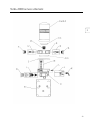
Dual Turbo-2000 dryer parts list
*H.C. Dual Turbo-2000 dryer parts list may be found on page 68.
A
A
B
C
D
619930
619922
619911
610077
610069
E
F
G
H
T224-P
619928
238
619932
H
619934
I
235
J
K
L
M
619110 12V 75W
619111 24V 75W
619935
619740
619938
N
O
Q
R
S
S
T
T
619980
619140
619920
619921
619910
619925
619912
619924
Component identification
Manifold
Manifold w/valves & fitting for 2-line version
Regeneration valve kit
Body gasket
Seal retainer
Note: four retainers per dryer, two on either side/1 per box
Desiccant cartridge with filtration plus package
Check valve nut
Check valve kit
Valve housing, complete with valves
& 12V heater
Valve housing, complete with valves
& 24V heater
Purge valve kit note: two valves per
dryer, one on either side/1 per box
12 Volt heater kit
24 Volt heater kit
Wire harness
Safety valve (200 psi)
Inlet check valve kit note: two valves
per dryer, one on either side/1 per box.
Mounting bracket
Cartridge stud
Mid-section L.H.
Mid-section R.H.
Air control valve - 3 fitting design
Air control valve - 2 fitting design
MLT 12 Volt
MLT 24 Volt
Bold part numbers represent suggested stock service components
620910 (620912*)
620920 (620924*)
620922
* Use 2 T224-P cartridges
48
Air dryer part number description
12V w/cartridges (w/o cartridges*)
24V w/cartridges (w/o cartridges*)
24V w/12V MLT & Special Mounting Bracket
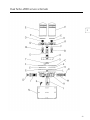
Dual Turbo-2000 service schematic
2
49
Normal Dual Turbo-2000 air dryer operation/cycle
1.The Micro Logic Timer (MLT) controls drying and regeneration cycles of the Dual Turbo-2000 air
dryer by energizing and de-energizing the Air Control Valve of air dryer at 90-second intervals.
An indicator light on MLT will be “on” during energized cycle and “off” during the
de-energized cycle. *
2.The air dryer’s Air Control Valve controls air flow direction through the dryer during the
compressor’s charge mode (pumping). During this charge mode, one dryer cartridge is drying air
and other cartridge is being regenerated.
3.During the compressor charge mode there will be a light flow of air from ONE exhaust port
of air dryer. This is normal, regeneration air flow and should be present ONLY when the
compressor is in charge mode (pumping). The air flow will alternate (every 90-seconds)
from one exhaust port to the other in conjunction with the MLT cycles. When the air dryer cycle
alternates during the compressor charge mode (pumping), there will be a momentary burst of air
from one of the air dryer exhaust ports. This is normal.
*MLT is polarity sensitive and will not operate if power (+) and ground (-) leads
are switched
Bottom View
Clean/dry air
Side View
Atmospheric pressure
Dirty/wet charged air
Dirty/wet purged air
50
Trouble-shooting Dual Turbo-2000
See H.C. Dual Turbo-2000 trouble-shooting for H.C. Dual Turbo-2000 on page 71
Review Dual Turbo-2000 normal operation / cycles prior to trouble-shooting on page 50
Problem: air continually flows from the exhaust port during compressor standby mode
Possible cause
Remedy
Worn check valve
Clean cavity and replace check valve assembly #238
Problem: system/wet tank air pressure drops rapidly
Possible cause
Remedy
Fittings are loose or damaged
Tighten and/or replace as necessary
Air reservoir, tubing, or hoses are
damaged
Repair or replace as necessary
Worn check valve
Clean cavity and replace check valve assembly #238
D2 governor malfunctioning
Replace governor
2
Problem: air compressor moves into the standby mode but cycles rapidly
Possible cause
Remedy
Fittings are loose or damaged
Tighten and/or replace as necessary
Air reservoir, tubing, or hoses are
damaged
Repair or replace as necessary
Worn check valve
Clean cavity and replace check valve assembly #238
D2 governor malfunctioning
Replace governor
51
con’t...
Problem: heavy air flow from one or both exhaust ports during compressor charge mode.
Note: alternating “light” air flow from exhaust ports during compressor charge mode is normal, regeneration air flow
Possible cause
Remedy
Worn purge valve or dirt/foreign material is stuck in
the purge valve
Clean cavities and replace purge valve assembly #235
Worn inlet check valve
Clean cavity and replace valve assembly #619915
Ice has formed in purge and/or inlet check valves,
heater assembly malfunctioning
Replace heater assembly #619110(12V) or valves
619111(24V)
Problem: air compressor runs continuously (system pressure will not build)
Possible cause
Remedy
Fittings are loose or damaged
Tighten or replace loose or damaged fittings
Air reservoir, tubing, or hoses are damaged
Repair or replace damaged items
The air compressor needs to be serviced or replaced Rebuild or replace the air compressor
52
Worn purge valve or dirt/foreign material is stuck in
the purge valve
Clean cavity and replace the purge valve assembly #235
The air compressor capacity is too low for vehicle
Install larger air compressor
Line between governor and air compressor is
blocked
Replace the line or remove the blockage
The safety valve is malfunctioning
Replace the safety valve #610024
Worn inlet check valve
Clean cavity and replace valve assembly #619915
Ice has formed in purge and/or inlet check valves,
heater assembly malfunctioning
Replace heater assembly #619110(12V) or 619111(24V)
D2 governor malfunctioning
Replace D2 governor
Air line (tubing) connecting dryer manifold and air
control valve missing or damaged
Repair/replace air line (tubing)
con’t...
Problem: air dryer does not exhaust during compressor charge mode
Possible cause
Remedy
Micro Logic Timer (MLT) malfunctioning
Replace MLT #619912 (12V) or 619924 (24V)
Air control valve malfunction
Replace air control valve #619910 (3 fittings) or 619925
(2 fittings)
Worn purge valve
Clean cavity and replace the purge valve assembly #235
Exhaust ports in purge valve and valve housing Align exhaust ports in purge valve and valve housing
not aligned
2
Repair/replace air line(s) (tubing)
Air line (tubing) connecting air control valve
and valve housing and/or manifold damaged or
missing
Ice has formed in the purge valve
Replace heater assembly #619110(12V) or 619111(24V)
Heater is malfunctioning
Replace heater assembly #619110(12V) or
619111(24V)
Problem: safety valve opens
Possible cause
Remedy
Air dryer outlet check valve is blocked
Clean cavity and replace the check valve assembly #238.
Air brake system is blocked down stream of air
dryer
Remove blockage or replace the necessary components
Air compressor governor malfunctioning
Replace compressor D2 governor
Air compressor unloader valve malfunctioning
Replace compressor unloader valve
Blocked desiccant cartridge(s)
Replace cartridge(s) #T224-P(s)
The safety valve is malfunctioning
Replace the safety valve #610024
Air dryer inlet check valve(s) is blocked
Clean cavity and replace the inlet check valve assembly #619915
53
con’t...
Problem: water accumulation in air system (tanks)
Possible cause
Remedy
Desiccant is contaminated
Replace desiccant cartridge #T224-P
Replace both cartridge and filters
Micro Logic Timer (MLT)
Replace MLT #619912 (12V) or #619924 (24V)
malfunctioning
Air control valve malfunction
Replace air control valve #619910 (3 fittings) or
#619925 (2 fittings)
Malfunctioning regeneration valve(s)
Clean cavity and replace regeneration valve(s) #619911
Air line (tubing) connecting air control valve and valve
housing and/or manifold damaged or missing
Repair/replace air line(s) (tubing) copper line or 12 feet of
steel braided Teflon ®
Line between the compressor and air dryer too short
(insufficient pre-cool)
Fit new line with a minimum length of 6 feet
Refer to vehicle manufacturer for specific test procedures for non related air dryer components.
*Teflon® is a registered trademark of E.I. DUPONT.
54
Service procedures Dual Turbo-2000
2
Purge Valve Service Kit #235,
Note: two (2) valves in dryer/1 per kit
Warning:Before proceeding read and follow safety precautions found on
page 17. Review description of “Normal” Dual Turbo-2000 Air
Dryer operation/cycle on page 50.
Symptom
1. Dryer won’t exhaust during charge cycle.
2.Large air leak at exhaust port(s) during
the charge mode.
Note: A light flow of air from one exhaust
port during charge cycle is normal, regeneration air flow.
3. Pressure slow or no build.
Operational check
Symptom #1:
Start engine and build system pressure. If dryer does not exhaust, during
the charge cycle, proceed as follows:
1. Check for blockage at exhaust port(s) of air dryer.
2. If item 1 OK, check and replace, if necessary, purge valve #235.
Note:Failure of dryer to exhaust could also be due to
malfunctioning MLT Valve. Refer to page 64-66 for service
procedure on this item.
55
con’t...
Symptom #2 & #3:
Start engine and build air pressure. During the charge cycle, check for large air
leak at exhaust port(s) of dryer. If large amount of air is leaking from exhaust port
proceed as follows:
1.Check and replace, if necessary, purge valve #235.
Note:Large air leak could also be due to worn inlet check valve. Refer to
page 56 for service on this valve.
Purge valve replacement (Two places)
1.Remove the two fasteners that attach the purge valve retainer. Remove the
retainer.
2.Remove the purge valve assembly and o-ring from the purge cavity and
discard.
Note:If there is excessive oil in the cavity, compressor may require
servicing.
3. Clean the cavity thoroughly.
4. Remove the three (3) o-rings from retainer and discard.
5. Using lubricant supplied, lightly grease the new o-rings.
6.Install on the retainer the two (2) larger o-rings then install the third
(smaller) o-ring.
7.Apply a light coating of grease around the o-ring seat on valve assembly.
Install the thin o-ring on the purge valve seat.
8.Insert valve assembly into cavity. Insure that valve exhaust port is aligned
with air dryer exhaust port. Use care not to dislodge the o-ring from its seat.
Warning:If the air dryer purge valve port does not align with air dryer
exhaust port, air dryer will not exhaust!
9. Install retainer.
10.Apply a light coating of grease on the threads
of the two retainer bolts.
11. Install two retainer bolts. Tighten to 10-15 ft. lb.
56
Service procedures Dual Turbo-2000
Check Valve Service Kit #238
Warning:Before proceeding read and follow
safety precautions found on page 17.
Review description of “Normal” Dual
Turbo-2000 Air Dryer operation/cycle
on page 50.
2
Symptom
1.Air continually flows from exhaust port when
compressor is in standby mode.
2.System/wet tank air pressure drops rapidly.
Operational check
Symptom #1 & #2
Start engine and build system air pressure to cutout pressure then
shut off engine. Allow at least 90 seconds for dryer to cycle through
regeneration cycle. Check for air leak at exhaust ports with soap/water
solution. If air leak is detected replace check valve #238.
Check valve replacement
1. Relieve all system air pressure.
2. Disconnect air line from dryer outlet port.
3. Remove check valve nut.
4. Remove and discard o-ring, spring, spindle, and ball.
5. Clean nut and check valve cavity thoroughly.
Note: If there is excessive oil in the cavity the desiccant cartridges
and filters require servicing.
6. Install new ball into cavity.
7. Install spindle, with spring pocket out, into cavity.
8. Place spring into spring pocket of spindle.
9.Apply a light coating of grease onto o-ring and place onto check
valve nut.
10.Apply light coating of grease to nut threads. Install nut and tighten
to 60 ft. lbs. torque.
11.Re-connect air line to outlet port.
57
Service procedures Dual Turbo-2000
Regeneration Valve Service Kit
#619911, Note: two (2) valves in
dryer/1 per kit
Warning:Before proceeding read and follow safety
precautions found on page 17. Review
description of “Normal” Dual Turbo-2000
Air Dryer operation/cycle on page 50.
Symptom
1. No purge air flow.
Note: A light flow of air from exhaust port(s)
during charge cycle is normal, regeneration
air flow.
2. Water in air tanks.
Operational check
Symptom #1 & #2:
Start engine and build air pressure. During the charge cycle
(compressor pumping), check for air flow at exhaust port(s)
of dryer. If no air flow is present replace regeneration valves
#619911.
Regeneration valve replacement (two valves)
1. Disconnect air line from outlet port of air dryer.
2.Remove eight (8) socket head bolts fastening
manifold to adaptor castings.
3. Remove manifold from adaptor castings.
4.Remove and discard o-rings, springs
and regeneration valves.
5. Clean valve cavities in adaptor castings.
6.Position new valve spindles into cavities
with spring pockets out.
7. Position springs into valves.
8.Lubricate new o-rings and install onto
manifold bosses.
9.Position manifold onto adaptor castings
ensuring o-rings are properly positioned in bores.
10.Install eight (8) socket head bolts
and tighten to 50-60 in. lbs. Torque.
11. Reconnect air line to outlet port.
58
Service procedures Dual Turbo-2000
2
Inlet Check Valve Service Kit #619938,
Note: two (2) valves in dryer/1 per kit
Warning:Before proceeding read and follow safety precautions
found on page 17. Review description of “Normal” Dual
Turbo-2000 Air Dryer operation/cycle on page 50.
Symptom
1. Large air leak at exhaust port(s) during the charge mode.
Note:A light flow of air from one exhaust port during
charge cycle is normal, regeneration air flow.
2. Pressure slow or no build.
Operational check
Symptom #1 & #2:
Start engine and build air pressure. During the charge cycle, check for
large air leak at exhaust port(s) of dryer. If large amount of air is leaking
from exhaust port, proceed as follows:
1. Check and replace, if necessary, inlet check valve #619915
Note:Large air leak could also be due to worn #235
Purge Valve. Refer to page 55 for service on this valve.
59
con’t...
Inlet Check valve replacement (Two places)
1.Remove two 1/4" bolts that fasten the inlet check valve
retainer to valve hsg. and removed retainer.
2.Remove the inlet check valve spindle from the inlet
cavity and discard.
Note: If there is excessive oil in cavity, compressor may require servicing.
3. Clean the cavity thoroughly.
4. Remove two (2) or one (1) o-ring(s) from seal retainer.
5. Install new o-ring on seal retainer.
Note: Only one (1) o-ring is required for proper function. The one (1) o-ring must be in groove located closest to retainer flange.
6.Lubricate all o-rings on new valve spindle and seal retainer before installing in
housing.
7. Lubricate bores in valve housing.
8.Install valve spindle assembly into housing bore
small end first and spring to outside as shown in drawing.
9.Make sure spindle is completely engaged in
cavity and moves freely.
10. Install retainer.
11. Apply grease to threads of retainer bolts.
12. Install retainer bolts and tighten to 10-15 ft. lbs.
60
Service procedures Dual Turbo-2000
Desiccant Cartridge Service
Kit #T224-P, Note: two (2) cartridges
on dryer/1 per kit
2
Warning:Before proceeding read and follow
safety precautions found on page 17
Operational check
Symptom
1. Regular service interval.
2. Water or contamination in tanks.
Symptom #1 & #2
Dessicant cartridge requires regular servicing at intervals determined by compressor duty
cycle or type of operating conditions. Typical service intervals are:
Inner City Transit
Inner City Refuse
Off Highway
2 years
2 years
2 years
Desiccant Cartridge, Filter Element and Internal Filter Plate Replacement
1. Relieve all system air pressure.
2. Disconnect heater lead wire from air dryer.
3. Disconnect air line from dryer inlet port.
4.Using a strap wrench, turn the desiccant cartridge counterclockwise and remove.
Discard.
4a. If cartridge spins without loosening, place a thin blade between cartridge gasket and base to break seal. If not,
4b. strike cartridge with a center punch or ball nose at the lower end where the diameter is slightly larger. This binds components together.
5.Remove and discard o-ring from adapter plate studs and filter elements (if present).
6.Remove four (4) 3/8" allen head bolts located at top of adapter plate castings.
7.Remove twelve (12) 3/8" hex head bolts attaching bottom valve housing to adapter
plate castings.
8. Remove bottom valve housing assembly.
61
con’t...
9.Remove two filter plates, gaskets and o-rings
(late model version only) and discard.
10.Clean valve housing sump, gasket surface and inside of two (2) adapter
plate castings of oil and contaminates.
11.Place new gasket or o-ring at each valve housing bolt flange.
12. Place new filter plate into each valve housing cavity. Position filter plates
in cavities, as shown in Fig. 1, with arrows pointed toward front of valve
housing.
13.Re-install valve housing assembly to adapter plate castings.
14. Torque (16) bolts to 25-30 ft. lbs.
15.Clean top surface of adapter plates and threaded studs.
16.Position new filter element around each stud and onto adapter plate.
17.Using grease supplied, apply a light coating of grease onto o-ring. Install
o-ring onto threaded studs.
18.Important for easy removal: Apply a generous coat of grease on the new
desiccant cartridge gasket surface.
19.Thread new cartridge onto studs turning clockwise. When gasket contacts
adapter plate, tighten cartridge 1/2 turn. Do not overtighten!
20. Re-connect air line top air dryer inlet port.
21. Re-connect heater lead wire.
62
Service procedures Dual Turbo-2000
Heater Service Kit
#619110 (12V) & #619111 (24V)
Warning:Read and follow safety precautions
found on page 17 before proceeding
2
Symptom
1. Dryer won’t exhaust.
2. Exhaust port leak.
3. Cannot build pressure.
Operational check
Note:Thermostat must be cooled to at least
35 degrees F to perform test.
Conduct continuity test by using an Ohmmeter or Test Light. Attach one lead
of test device to one terminal of heater connector and other lead of test device
to other terminal of heater connector. The test light should light or Ohmmeter
indicates continuity. If there is NO continuity, replace heater/thermostat
assembly.
Heater assembly replacement
1. Disconnect heater lead wire.
2. Remove two screws attaching heater connector to casting.
3. Remove heater/thermostat assembly and discard.
4. Thoroughly clean entire heater/thermostat area.
5.Slide o-ring over heater and thermostat into position
around connector flange.
6.Apply a light coating of anti-seize to the heater
element and thermostat cavity.
7.Insert heater element into hole and twist slightly to spread anti-seize.
8.Place thermostat into position in cavity and ensure
thermostat sits flat in cavity.
9.Place foam cube on top of thermostat and bring heater connector into
position over cavity.
10. Secure heater connector using the (2) 8-32 x 1/2" screws.
11. Reconnect Metri-Pak connector to male plug.
Note:If heater lead wire with male plug needs to be replaced
or is not in vehicle wire harness, it is available in Kit #619935.
63
Service procedures Dual Turbo-2000
Air Control Valve
Service Kit #619910 & #619925
Warning:Before proceeding read and follow safety precautions
found on page 17. Review description of “normal” Dual
Turbo-2000 Air Dryer operation/cycle on page 50.
Symptom
1.Dryer won’t exhaust during charge cycle to allow regeneration
air flow at 90 second intervals.
Note: A
light flow of air from ONE exhaust
port during charge cycle is normal
regeneration air flow.
2. Water in air tanks.
Operational check:
Drain tanks, check for excessive oil and water
64
con’t...
Symptom #1 & #2
Start engine and begin building system air pressure. After approximately 90 seconds into
charge cycle, an exhaust burst should occur from one exhaust port. If exhaust does not
occur proceed as follows:
2
1.During the charge cycle, turn the brass screw located on air valve (see Fig. 1 on page
64), to the right (screw slot will be in horizontal position). If exhaust air burst does
not occur, replace valve. If exhaust does occur, turn screw back to original position
(screw slot must be in vertical position for normal operation) and proceed to step 2.
2.Failure of dryer to exhaust could also be due to malfunctioning purge valve or MLT.
Refer to pages 50 & 55 respectively for service of these items.
Air control valve replacement
1. Un-plug electrical connector from MLT/Valve.
2.Remove three (3) air lines (Kit #619910) or two (2) air lines
(Kit #619925) connected to fittings in air valve (Ref. Fig 1 on
page 64).
3.Remove retaining nut holding MLT assembly to valve stem and remove MLT
assembly from valve. Set aside nut and MLT for later re-assembly.
4.Remove three (3) screws holding valve to manifold. Remove valve and discard.
5. Install air valve #619910 (three fittings) as follows:
a. Install three (3) push connect fittings to open ports
of new air valve.
b. Secure air valve to manifold with three (3) screws.
Torque screws to 15-20 in. lbs.
c. Re-connect air line from manifold to front port of air valve.
d. Re-connect two remaining air lines to back ports of valve.
OR
5. Install air valve #619925 (two fittings) as follows:
a. Install two (2) push connect fittings to open ports of new air valve.
b. Place small o-ring at small hole on top of valve body.
c. Position air valve against bottom of manifold, insuring the small o-ring fits into
counter bore located on bottom of manifold.
d. Secure air valve to manifold with three (3) screws. Torque screws to 15-20 in. lbs.
e. Re-connect two air lines to back ports of valve.
6.Re-assemble MLT assembly to valve stem and secure
with retaining nut.
7. Re-connect electrical plug to MLT.
65
Service procedures Dual Turbo-2000
Micro Logic Timer (MLT)
Service Kit: #619912 (12V), #619924 (24V)
Warning:Before proceeding read and follow
safety precautions found on page 17.
Review description of “normal” Dual Turbo-2000
Air Dryer operation/cycle on page 50.
Symptom
1.Dryer won’t exhaust during charge cycle to allow
regeneration air flow at 90 second intervals.
Note:A light flow of air from ONE exhaust port during
charge cycle is normal regeneration air flow.
2. Water in air tanks.
Operational check
Symptom #1 & #2
Start engine and begin building system air pressure. After approximately 90
seconds into charge cycle, an exhaust air burst should occur from one exhaust port.
Note:No exhaust air burst will occur during compressor
stand-by or non charge cycle. If exhaust air burst does not occur during
charge cycle, proceed as follows:
1.Insure that power is present at MLT connector and that all electrical
connections are properly connected.
Note: M
LT is polarity sensitive and will not operate if power (+) and ground
(-) leads are switched. The MLT energizes and de-energizes air valve
at 90 second intervals. An indicator light on MLT will be on during
energize cycle and off during de-energized cycle. If all electrical
connections are good replace MLT.
2.Failure of dryer to exhaust could also be due to malfunctioning purge valve
and Air Control Valve. Refer to pages 55 and 64 respectively for service of
these items.
MLT Replacement
1. Un-plug electrical lead wire from MLT connector.
2.Remove retaining nut holding MLT to valve stem and
remove MLT from valve. Set aside nut for later re-assembly.
3.Re-assemble new MLT to valve stem and secure with retaining nut.
4. Re-connect electrical plug to MLT.
66
Dual Turbo-2000 Notes:
2
67
H.C. Dual Turbo-2000 parts list
Component identification
A
B
619933
619913
C
D
610077
610069
E
F
G
H
T224-P
619928
238
619972
619974
I
235
J
619110
619111
619900
619740
619938
K
L
M
N
O
Manifold/mid-section assembly (with valves)
Regeneration valve kit
Note: Two valves per dryer, one on either side
Body gasket
Seal retainer
Note: Four retainers per dryer, two on either side
Desiccant cartridge with Filtration Plus
Check valve nut
Check valve kit
Valve housing, complete w/valves, 12V heater & housing bolts
Valve housing, complete w/valves, 24V heater & housing bolts
Purge valve kit
Note: Two valves per dryer, one on either side
12 Volt heater kit
24 Volt heater kit
Wire harness
Safety valve (200 psi)
Inlet check valve kit
Note: Two valves per dryer, one on either side
Mounting bracket
Cartridge stud
Control line service kit (not shown)
Service kit contains (2) T224-P, (2) 235, (2) 619938, (1) 238, (1) 619111,
(1) 619740 & (12) housing bolts
619980
619140
619973
619979
Bold part numbers represent suggested stock service components
620930
620980
620982
620984
68
Air dryer part number description
24 V DLU application w/o purge tanks; min 600 cu.in. purge
volume required
12 V with 2 #221 purge tanks
12 V without purge tanks; min 600 cu.in. purge volume
required
24 V without purge tanks; min 600 cu.in. purge volume
required
620986
24 V with 2 #221 purge tanks
619228
Purge tank kit w/690 cu.in. purge volume
H.C. Dual Turbo-2000 service schematic
2
69
H.C. Dual Turbo-2000 normal operation / cycles – use with high output compressors
Air flows from the compressor into the air dryer. Air flows past filters and both desiccant beds
stripping moisture and contaminants from air and exits dryer to the purge tank(s) and to the wet tank.
If two purge tanks are used, T air lines to allow air to flow to both tanks simultaneously. The reservoir
line from the wet tank to the governor is always pressurized.
When pressure reaches cut-out (typically 120-125 psi), the governor sends air signal through the
governor line to the air dryer opening both purge valves and closing both inlet check valves. The check
valve is closed via back pressure from wet tank. Then, air in the purge tank(s) re-enters the dryer and
passes through both desiccant beds taking away moisture and is expelled out bottom exhaust ports of
air dryer. Turbo boost from the compressor is checked at inlet check valve of dryer.
When the pressure drops to cut-in (typically 90-95 psi), the air in the UNL line evacuates out the
exhaust port of the governor closing purge valves and opening inlet check valves and once again air
flows from the compressor into the air dryer.
SKF Brakemaster® H.C. Dual Turbo-2000 air dryer service schematic
70
Trouble-shooting H.C. Dual Turbo-2000
See Dual Turbo-2000 trouble-shooting for Dual Turbo-2000 on page 51
Review H.C. Dual Turbo-2000 normal operation / cycles prior to trouble-shooting on page 70
Problem: air continually leaks from the exhaust port during compressor standby mode
Possible cause
Remedy
Worn check valve
Clean cavity and replace check valve assembly #238
Worn inlet check valves
Clean cavity and replace inlet check valve assemblies #619938
Worn purge valve seals
Clean cavity and replace purge valve assemblies #235
2
Problem: system air pressure drops rapidly
Possible cause
Remedy
Fittings are loose or damaged
Tighten and/or replace as necessary
Air reservoir, tubing,
or hoses are damaged
Repair or replace as necessary
Worn check valve
Clean cavity and replace check valve assembly #238
Worn inlet check valves
Clean cavity and replace inlet check valve assembly #619938
Worn purge valve seals
Clean cavity and replace purge valve assemblies #235
Problem: air compressor moves into the standby mode but cycles rapidly
Possible cause
Remedy
Fittings are loose or damaged
Tighten and/or replace as necessary
Air reservoir, tubing, or hoses are
damaged
Repair or replace as necessary
Worn check valve
Clean cavity and replace check valve assembly #238
Worn inlet check valves
Clean cavity and replace inlet check valve assemblies #619938
D2 governor malfunctioning
Replace governor
Worn purge valve seals
Clean cavity and replace purge valve assemblies #235
Problem: air leaks from the exhaust port during compressor charge mode
Possible cause
Remedy
Worn purge valves
Clean cavities and replace purge valve assemblies #235
Dirt/foreign material
is stuck in the purge valves
Clean cavity and replace valve assemblies #235
D2 governor malfunctioning
Replace D2 governor
Heater assembly malfunctioning (>32
degrees)
Replace heater assembly #619110(12V) or #619111(24V)
71
con’t...
Problem: air compressor runs continuously (system pressure will not build)
Possible cause
Remedy
Fittings are loose or damaged
Tighten or replace loose or damaged fittings
Air reservoir, tubing, or hoses are damaged
Repair or replace damaged items
The air compressor needs to be serviced or
replaced
Rebuild or replace the air compressor
Worn purge valves
Clean cavity and replace the purge valve assemblies #235
The air compressor capacity is too low for vehicle
Install larger air compressor
Line between governor and air compressor is
blocked
Replace the line or remove the blockage
The safety valve is malfunctioning
Replace the safety valve #619740
Ice has formed in the purge valve
Replace heater assembly #619110(12V) or #619111(24V)
D2 governor malfunctioning
Replace D2 governor
Problem: air dryer does not exhaust during compressor standby mode
Possible cause
Remedy
The line between the air governor and the air
dryer control port is missing, leaking, or damaged
Install or replace the air line, or tighten the fittings
Worn purge valves
Clean cavity and replace purge valve assemblies #235
Ice has formed in the purge valve
Replace heater assembly #619110(12V) or #619111(24V)
Heater is malfunctioning
Replace heater assembly #619110(12V) or #619111(24V)
Purge valve sleeves are misaligned
Align purge valve sleeves
Problem: safety valve opens
Possible cause
Remedy
Air dryer check valve is blocked
Clean cavity and replace check valve assembly #238
Air brake system is blocked down stream of air
dryer
Remove blockage or replace the necessary components
Air compressor governor malfunctioning
Replace compressor D2 governor
Blocked desiccant cartridge
Replace cartridge #T224-P*
The safety valve is malfunctioning
Replace the safety valve #619740
*Air compressor service may be required to address excessive oil blow-by.
72
con’t...
Problem: water accumulation in air system (tanks)
Possible cause
Remedy
Desiccant is contaminated
Replace both desiccant cartridges #T224-P
The air compressor capacity is too low for
vehicle
Install larger air compressor and replace desiccant cartridges #T224-P
Malfunctioning regeneration valves
Clean cavity and replace regeneration valve
assemblies #619913
The line between the purge tank and the
air dryer control port is missing, leaking, or
damaged
Install or replace the air line, or tighten the fittings
Line between the compressor and air dryer
too short
Fit new line with a minimum length of 6 feet copper line or (insufficient
pre-cool) 12 feet of steel braided Teflon ®*
2
Refer to vehicle manufacturer for specific test
procedures for non related air dryer components.
* Teflon
®
is a registered trademark of E.I. DuPont.
73
Service procedures H.C. Dual Turbo-2000
Purge Valve Service Kit #235
Warning:Read and follow safety precautions
found on page 17 before proceeding
Symptom
1. Dryer won’t exhaust
2. Air leak at exhaust ports during the:
a) Charge mode
b) Stand-by mode
3. Slow or no pressure build
4. Compressor cycles rapidly
Operational check
Symptom #1:
Start engine and build to cutout pressure. If dryer does not exhaust
proceed as follows:
1.Check for air pressure in line connecting D2 governor to T-fitting on
air dryer. If no pressure is present in line, service D2 governor.
2. Check for blockage at exhaust ports of air dryer.
3. If items 1 and 2 are OK, replace both purge valves #235.
Note: No exhaust could also be an obstructed regeneration
valve #619913.
Symptom #2A & #3:
Start engine and build air pressure. During the charge cycle, check
for air leaking at exhaust ports of dryer. If air is leaking from one or both
exhaust ports proceed as follows:
1.No air pressure should be present in line connecting D2
governor and dryer purge valve during charge cycle. If there
is, service D2 governor.
2. If item 1 is OK, replace one or both purge valves #235
Symptom #2B & #4:
Start engine and build to cut out pressure. Stop engine. Allow one minute
for purge air to discharge dryer. If air continues to discharge from exhaust
port of dryer, replace one or both purge valves #235.
Note: Air discharge could also be due to worn check valve
or inlet check valve. There are two inlet check valves.
74
con’t...
Purge valve replacement
1. Disconnect air line at each control port.
2.Remove the two fasteners that attach the
purge valve retainer. Remove the retainer.
3.Remove the purge valve assembly from the
purge cavity and discard.
2
Note: If there is excessive oil in the cavity, compressor
may require servicing.
4. Clean the cavity thoroughly.
5. Remove the three (3) o-rings from retainer and discard.
6. Using lubricant supplied, lightly grease the new o-rings.
7.Install on the retainer the two- (2) thickest o-rings then
install the third (thinner) o-ring.
8.Install the new filter screen in the purge cavity open end out.
9.Apply a light coating of grease around the o-ring seat on
valve assembly. Install the thin o-ring on the purge valve seat.
10.Aligning the valve exhaust port with the air dryer exhaust port, install
the purge valve assembly. Use care not to dislodge the
o-ring from its seat.
Warning: If the air dryer purge valve port does not align
with air dryer exhaust port, air dryer will not exhaust!
11. Install retainer.
12.Apply a light coating of grease on the threads
of the two retainer bolts.
13.Install two retainer bolts. Tighten to 10-15 ft. lb.
14. Reconnect the control line to air dryer control port.
75
Service procedures H.C. Dual Turbo-2000
Regeneration Valve Service Kit #619913
Warning:Read and follow safety precautions
found on page 17 before proceeding
Symptom
1. Water in tanks.
2. No purge air flow.
Operational check
Symptom #1 & #2:
Start engine and build to cut-out pressure. Stop engine. After initial
exhaust, air should flow with decreasing intensity out both exhaust ports
for approximately 45 seconds. If air fails to flow, replace the affected
regeneration valve kit #619913.
Note: Water in tanks could also be due to worn purge valve, or
T-224-P dessicant cartridges are ready for service. No purge
air could be attributed to governor or purge valve.
Regeneration valve replacement (two valves)
1. Disconnect air line from outlet port of air dryer.
2.Remove eight (8) socket head bolts fastening
manifold to adaptor castings.
3. Remove manifold from adaptor castings.
4.Remove and discard o-rings, springs
and regeneration valves.
5. Clean valve cavities in adaptor castings.
6.Position new valve spindles into cavities
with spring pockets out.
7. Position springs into valves.
8.Lubricate new o-rings and install onto
manifold bosses.
9.Position manifold onto adaptor castings
ensuring o-rings are properly positioned in bores.
10.Install eight (8) socket head bolts
and tighten to 50-60 in. lbs. Torque.
11. Reconnect air line to outlet port.
76
Service procedures H.C. Dual Turbo-2000
Check Valve Service Kit #238
Warning:Read and follow safety precautions found on
page 17 before proceeding
2
Symptom
1. Dryer frequently exhausts.
2.Air continually flows from exhaust port
when compressor is in standby mode.
3. Wet tank pressure drops rapidly.
Operational check
Symptom #1, #2, & #3:
Start engine and build to cut out pressure. Stop engine. Allow one
minute for purge air to discharge dryer. If air continues to discharge
from exhaust port of dryer, replace check valve #238.
Note: Air discharge could also be due to worn purge valve
or inlet check valve. The affected inlet check valve
would be located on side of air dryer.
Check valve replacement
1. Drain air system.
2. Disconnect air line from outlet port.
3. Remove check valve nut.
4. Remove and discard o-ring, spring, spindle, and ball.
Note: If there is excessive oil in the check valve cavity, compressor
may require servicing.
5. Clean nut and cavity area.
6.Install new ball in cavity. Next, position spindle
with spring pocket facing out. Install spring.
7.Using grease supplied, apply a light coating on o-ring.
Install o-ring on nut.
8.Apply a light coating of grease to threads of nut.
Install nut and tighten to 60 ft. lb.
9. Re-connect air line to air dryer outlet port.
77
Service procedures H.C. Dual Turbo-2000
Inlet Check Valve Service Kit #619938,
Note: two (2) valves in dryer/1 per kit
Warning:Before proceeding read and follow safety precautions
found on page 17.
Symptom
1. Air leak at exhaust port(s) during the charge mode.
2. Pressure slow or no build.
Operational check
Symptom #1 & #2:
Start engine and build air pressure. During the charge cycle, check for air
leak at exhaust port(s) of dryer. If air is leaking from exhaust port, proceed
as follows:
1. Check and replace, if necessary, inlet check valve #619938
Note: Air leak could also be due to worn #235
Purge Valve. Refer to page 74 for service on this valve.
78
con’t...
Inlet Check valve replacement (Two places)
1.Remove two 1/4" bolts that fasten the inlet check valve
retainer to valve hsg. and removed retainer.
2.Remove the inlet check valve spindle from the inlet
cavity and discard.
2
Note: If there is excessive oil in cavity, compressor may
require servicing.
3. Clean the cavity thoroughly.
4. Remove two (2) or one (1) o-ring(s) from seal retainer.
5. Install new o-rings on seal retainer. Three (3) o-rings are required.
6.Lubricate all o-rings on new valve spindle and seal retainer before
installing in housing.
7. Lubricate bores in valve housing.
8.Install valve spindle assembly into housing bore
small end first and spring to outside as shown in drawing.
9.Make sure spindle is completely engaged in
cavity and moves freely.
10. Install retainer.
11. Apply grease to threads of retainer bolts.
12. Install retainer bolts and tighten to 10-15 ft. lbs.
79
Service procedures H.C. Dual Turbo-2000
Desiccant Cartridge Service
Kit #T224-P, Note: two (2) cartridges
on dryer/1 per kit
Warning:Before proceeding read and follow
safety precautions found on page 17
Operational check
Symptom
1. Regular service interval.
2. Water or contamination in tanks.
Symptom #1 & #2
Dessicant cartridge requires regular servicing at intervals determined
by compressor duty cycle or type of operating conditions. Typical service
intervals are:
Inner City Transit
Inner City Refuse
Off Highway
2 years
2 years
2 years
Desiccant Cartridge, Filter Element and Internal Filter Plate
Replacement
1. Relieve all system air pressure.
2. Disconnect heater lead wire from air dryer.
3. Disconnect air line from dryer inlet port.
4.Using a strap wrench, turn the desiccant cartridge counterclockwise
and remove. Discard.
4a. If cartridge spins without loosening, place a thin blade between cartridge gasket and base to break seal. If not,
4b. strike cartridge with a center punch or ball nose at the lower
end where the diameter is slightly larger. This binds components together.
5.Remove and discard o-ring from adapter plate studs and filter
elements (if present).
80
con’t...
6.Remove four (4) 3/8" allen head bolts located at top of adapter plate
castings.
7.Remove twelve (12) 3/8" hex head bolts attaching bottom valve
housing to adapter plate castings.
2
8. Remove bottom valve housing assembly.
9.Remove two filter plates, gaskets and o-rings
(late model version only) and discard.
10.Clean valve housing sump, gasket surface and inside of two (2)
adapter plate castings of oil and contaminates.
11.Place new gasket or o-ring at each valve housing bolt flange.
12. Place new filter plate into each valve housing cavity. Position filter
plates in cavities, as shown in Fig. 1, with arrows pointed toward
front of valve housing.
13.Re-install valve housing assembly to adapter plate castings.
14. Torque (16) bolts to 25-30 ft. lbs.
15.Clean top surface of adapter plates and threaded studs.
16.Position new filter element around each stud and onto adapter plate.
17.Using grease supplied, apply a light coating of grease onto o-ring.
Install o-ring onto threaded studs.
18.Important for easy removal: Apply a generous coat of grease on
the new desiccant cartridge gasket surface.
19.Thread new cartridge onto studs turning clockwise. When
gasket contacts adapter plate, tighten cartridge 1/2 turn. Do not
overtighten!
20. Re-connect air line top air dryer inlet port.
21. Re-connect heater lead wire.
81
Service procedures H.C. Dual Turbo-2000
Heater Service Kit
#619110 (12V) & #619111 (24V)
Warning:Read and follow safety precautions
found on page 17 before proceeding
Symptom
1. Dryer won’t exhaust.
2. Exhaust port leak.
3. Cannot build pressure.
Operational check
Note:Thermostat must be cooled to at least
35 degrees F to perform test.
Conduct continuity test by using an Ohmmeter or Test Light. Attach one
lead of test device to one terminal of heater connector and other lead of
test device to other terminal of heater connector. The test light should light
or Ohmmeter indicates continuity. If there is NO continuity, replace heater/
thermostat assembly.
Heater assembly replacement
1. Disconnect heater lead wire.
2. Remove two screws attaching heater connector to casting.
3. Remove heater/thermostat assembly and discard.
4. Thoroughly clean entire heater/thermostat area.
5.Slide o-ring over heater and thermostat into position
around connector flange.
6.Apply a light coating of anti-seize to the heater
element and thermostat cavity.
7.Insert heater element into hole and twist slightly
to spread anti-seize.
8.Place thermostat into position in cavity and ensure
thermostat sits flat in cavity.
9.Place foam cube on top of thermostat and bring heater connector into
position over cavity.
10. Secure heater connector using the (2) 8-32 x1/2" screws.
11. Reconnect Metri-Pak connector to male plug.
Note:If heater lead wire with male plug needs to be replaced
or is not in vehicle wire harness, it is available in Kit #619935.
82
H.C. Dual Turbo-2000 Notes:
2
83
Turbo-3000 parts list
A
B
C
D
E
F
G
H
I
J
J
K
L
M
N
238
610236
610077
619086
619112
619087
619113
228
610069
235
T334
610024
248 12V 75W
249 24V 75W
619110 12V 75W
619111 24V 75W
619900
619115
619140
619091
619093
Component identification
Check valve kit
Check valve nut
Body gaskets
Bottom cap assembly 12V STD
Bottom cap assembly 12V E-Type
Bottom cap assembly 24 STD
Bottom cap assembly 24 E-Type
Turbo valve kit
Seal retainer
Purge valve kit
Desiccant cartridge kit
Safety valve (175 psi)
Heater kit early models
(Orange and blue wires)
Heater kit late models
(Plug style connection)
Wire harness
Mounting bracket
Cartridge stud kit
Mid-section with valves STD
Mid-section with valves E-Type
Bold part numbers represent suggested stock service components
STD
620640
620642
Dryer part number description
E Type*
Description
620540
Dryer 12V
620542
Dryer 24V
*Holset SS E-Type and QE compressor
For right-hand models see parts list on pages 139 & 140.
84
Turbo-3000 service schematic
2
85
Turbo-3000 normal operation/cycles – light duty applications only
Air flows from the compressor into the air dryer. Air flows past filters and desiccant bed stripping
moisture and contaminants from air and exits dryer to the wet tank. The reservoir line from the wet
tank to governor is always pressurized.
When pressure reaches cut-out (typically 120-125 psi), the governor sends an air signal through the
governor line to the air dryer opening the purge valve and closing the turbo valve. The check valve
is closed via back pressure from the wet tank. Then, regeneration air contained in cartridge passes
through the desiccant bed taking away moisture and is expelled out bottom of air dryer. Turbo boost
from the compressor is checked at inlet of dryer with closed turbo valve. E-Type dryers provide back
pressure to the compressor during stand-by. This feature is not intended for use for any compressor
other than Holset E-Type compressors.
When the pressure drops to cut-in (typically 90-95 psi), the air in the UNL line evacuates out the
exhaust port of the governor closing purge valve and opening turbo valve and once again flows from
the compressor into the air dryer.
Charge cycle
Clean/dry air
Atmospheric pressure
Purge cycle
Dirty/wet charged air
Dirty/wet purged air
Note: Approx. 95PSI gov cut in, 120PSI gov cut out
86
Trouble-shooting Turbo-3000 dryer
Review Turbo-3000 normal operation / cycles prior to trouble-shooting on page 86
Problem: air continually leaks from the exhaust port in compressor standby mode
Possible cause
Remedy
Worn check valve
Clean cavities and replace check valve assembly #238
Worn turbo valve
Clean cavities and replace turbo valve assembly #228
Worn purge valve seal
Clean cavities and replace purge valve assembly #235
2
Problem: system air pressure drops rapidly
Possible cause
Remedy
Fittings are loose or damaged
Tighten and/or replace as necessary
Air reservoir, tubing, or hoses are damaged
Repair or replace as necessary
Worn check valve
Clean cavity and replace check valve assembly #238
Worn turbo valve
Clean cavity and replace turbo valve assembly #228
Worn purge valve seal
Clean cavity and replace purge valve assembly #235
Problem: air compressor goes into the standby mode but cycles rapidly
Possible cause
Remedy
Fittings are loose or damaged
Tighten and/or replace as necessary
Air reservoir, tubing, or hoses are damaged
Repair or replace as necessary
Worn check valve
Clean cavity and replace check valve assembly #238
Worn turbo valve
Clean cavities and replace turbo valve assembly #228
D2 governor malfunctioning
Replace D2 governor
Worn purge valve seal
Clean cavity and replace the purge valve assembly #235
Problem: air leaks from the exhaust port during compressor charge mode
Possible cause
Remedy
Worn purge valve
Clean cavity and replace the purge valve assembly #235
Dirt/foreign material is stuck in purge valve
Clean cavity and replace the purge valve assembly #235
D2 governor malfunctioning
Replace D2 governor
Heater assembly malfunctioning (>32˚ F)
Replace heater assembly #246(12V), 247(24V), 248(12V),
249(24V), 619110(12V) or 619111(24V)
87
con’t...
Problem: air compressor runs continuously (system pressure will not build)
Possible cause
Remedy
Fittings are loose or damaged
Tighten or replace loose or damaged fittings
Air reservoir, tubing, or hoses are
damaged
Repair or replace damaged items
Air compressor needs to be serviced or Rebuild or replace the air compressor
replaced
Worn purge valve
Clean cavities and replace the purge valve assembly #235
Air compressor capacity is too low for
vehicle
Install larger air compressor and upgrade to Turbo-2000
Air line between governor and air
compressor is blocked
Replace the line or remove the blockage
The safety valve is malfunctioning
Replace the safety valve #610024
D2 governor malfunctioning
Replace D2 governor
Ice has formed in the purge valve
Replace heater assembly #246(12V), 247(24V), 248(12V),
249(24V), 619110(12V) or 619111(24V)
Problem: air dryer does not exhaust during compressor standby mode
Possible cause
Remedy
Line between the air governor and the
dryer control port is missing, leaking
or damaged
Install or replace the air line or tighten the fittings
Worn purge valve
Clean cavity and replace purge valve assembly #235
Ice has formed in the purge valve
Replace heater assembly #246(12V), 247(24V), 248(12V) 249(24V),
619110(12V) or 619111(24V)
Heater is malfunctioning
Replace heater assembly #246(12V), 247(24V), 248(12V), 249(24V),
619110(12V) or 619111(24V)
Purge valve sleeve is misaligned
Align purge valve sleeve
Problem: the safety valve opens
Possible cause
Remedy
The air dryer check valve is blocked
Clean cavity and replace the check valve assembly #238
The air system is blocked down stream Remove blockage or replace necessary components
from the air dryer
88
Malfunctioning D2 governor
Replace the D2 governor
Blocked desiccant cartridge
Replace cartridge #T334
The safety valve is malfunctioning
Replace the safety valve #610024
con’t...
Problem: water accumulation in air system (tanks)
Possible cause
Remedy
Desiccant is contaminated
Replace desiccant cartridge #T334 or upgrade to
Turbo-2000
Air compressor capacity is too low for vehicle
Install larger air compressor and upgrade to
Turbo-2000
Line length between the compressor and air dryer
(insufficient pre-cool)
Fit new line with a minimum length of 6 feet
copper or 12 feet of steel braided Teflon ®
Air dryer capacity is too low for compressor
Upgrade to Turbo-2000
Note: Turbo-3000 is rated up to 15 cfm
2
Refer to vehicle manufacturer for specific test
procedures for non related air dryer components.
89
Service procedures Turbo-3000
Purge Valve Service Kit #235
Warning:Read and follow safety precautions
found on page 17 before proceeding
Symptom
1. Dryer won’t exhaust.
2. Air leak at exhaust port during the:
a) Charge mode
b) Stand-by mode
3. Pressure slow or no build.
4. Compressor cycles rapidly.
Operational check
Symptom #1:
Start engine and build to cutout pressure. If dryer does
not exhaust proceed as follows:
1.Check for air pressure in line connecting D2 governor
to control port of air dryer. If no pressure is present in line, service
D2 governor.
2. Check for blockage at exhaust port of air dryer.
3. If items 1 and 2 are OK, replace purge valve #235.
Symptom #2A & #3:
Start engine and build air pressure. During the charge cycle check for
air leaking at exhaust port of dryer. If air is leaking from exhaust port,
proceed as follows:
1.No air pressure should be present in line connecting D2 governor
and control port during charge cycle. If there is, service D2
governor.
2. If item 1 is OK, replace purge valve #235.
Symptom #2B & #4:
Start engine and build to cut out pressure. Stop engine. Allow one
minute for purge air to discharge dryer. If air continues to discharge from
exhaust port of dryer, replace purge valve #235.
Note: A
ir discharge could also be due to worn check valve or turbo
valve. Refer to pages 92 and 93 for service procedures on
these valves.
90
con’t...
Purge valve replacement
1. Disconnect air line at control port.
2.Remove the two fasteners that attach the
purge valve retainer. Remove the retainer.
3.Remove the purge valve assembly from the
purge cavity and discard.
2
Note:If there is excessive oil in the cavity, compressor may require
servicing and/or upgrade to Turbo-2000.
4. Clean the cavity thoroughly.
5. Remove the three (3) o-rings from retainer and discard.
6. Using lubricant supplied, lightly grease the new o-rings.
7.Install on the retainer the two (2) thickest o-rings then install the
third (thinner) o-ring.
8.Install the new filter screen in the purge cavity open end out.
9.Apply a light coating of grease around the o-ring seat on valve
assembly. Install the thin o-ring on the purge valve seat.
10.Aligning the valve exhaust port with the air dryer exhaust port,
install the purge valve assembly. Use care not to dislodge the
o-ring from its seat.
Warning:If the air dryer purge valve port does not align with air
dryer exhaust port, air dryer will not exhaust!
11. Install retainer.
12.Apply a light coating of grease on the threads
of the two retainer bolts.
13. Install two retainer bolts. Tighten to 10-15 ft. lb.
14. Reconnect air line to control port.
91
Service procedures Turbo-3000
Check Valve Service Kit #238
Warning:Read and follow safety precautions
found on page 17 before proceeding
Symptom
1. Dryer frequently exhausts.
2.Air continually flows from exhaust port
when compressor is in standby mode.
3. Wet tank pressure drops rapidly.
Note:The above symptoms could also lead to turbo valve
replacement. A malfunctioning turbo valve will tend
to allow pressure to drop to cut-in pressure within
seconds on E-Type style air dryers.
Operational check
Symptoms #1, #2, #3
Start engine and build to cut out pressure. Stop engine. Allow one
minute for purge air to discharge dryer. If air continues to discharge from
exhaust port of dryer, replace check valve #238.
Note: Air discharge could also be due to worn purge valve
or turbo valve.
Check valve replacement
1. Drain air system.
2. Disconnect air line from outlet port.
3. Remove check valve nut.
4. Remove and discard o-ring, spring, spindle, and ball.
Note: If there is excessive oil in the check valve
cavity, compressor may require servicing.
5. Clean nut and cavity area.
6.Install new ball in cavity. Next, position spindle
with spring pocket facing out. Install spring.
7.Using grease supplied, apply a light coating on o-ring.
Install o-ring on nut.
8.Apply a light coating of grease to threads of nut. Install nut and
tighten to 60 ft. lb.
9. Re-connect air line to air dryer outlet port.
92
Service procedures Turbo-3000
Turbo Valve Service Kit #228
Warning:Read and follow safety precautions
found on page 17 before proceeding
2
Symptom
1. Dryer frequently exhausts.
2.Air continually flows from exhaust port
when compressor is in standby mode.
3. System pressure drops very rapidly.
Note: The above symptoms could also
lead to Check valve replacement.
Operational check
Symptom #1, #2 & #3
tart engine and build to cut out pressure. Stop engine. Allow one
S
minute for purge air to discharge dryer. If air continues to discharge from
exhaust port of dryer, replace turbo valve #228.
Note: Air discharge could also be due to worn purge valve
or check valve.
Turbo valve replacement
1. Drain the air system.
2. Disconnect the heater wiring.
3.Disconnect the inlet and control lines from
their respective ports.
4.Remove 8 bolts from bottom cap and set aside.
Discard gasket.
5. Remove turbo nut, valve stop and valve and discard.
6. Clean cavity area thoroughly.
7. Lightly coat the 2 (small) o-ring surfaces and install on
piston. Carefully install valve in cavity with tapered side up.
8. Place valve stop on top of valve concave side down.
9.Lightly lube (large) o-ring and place on nut.
Install flat seal into nut.
10. Install nut and tighten to 40-45 ft. lb.
11.Place gasket on bottom cap aligning all holes.
Locate bottom cap so that inlet port is directly below
outlet port. Install (8) bolts. Tighten bolts to 20-25 ft. lb.
or 25-30 ft. lb. if equipped with oil separator.
12. Re-connect inlet and control lines to air dryer.
13. Re-connect heater wiring.
93
Service procedures Turbo-3000
Dessicant Cartridge
Service Kit #T334
Warning:Read and follow safety precautions
found on page 17 before proceeding
Symptom
1. Regular service interval.
2. Water in tanks.
Operational check
Symptom #1 & #2
Desiccant cartridge requires regular servicing at intervals
determined by compressor duty cycle or type of driving conditions.
Check air reservoirs on regular basis opening drain valves.
If moisture exists, replace cartridge #T334.
Desiccant cartridge replacement
1. Drain the air system.
2.Using a strap wrench, turn the desiccant cartridge counterclockwise
and remove it. Discard.
3. Remove and discard o-ring from adapter plate stud.
Note:If there is excessive oil present, compressor may require
servicing and/or an oil separator, kit #619650 may be
required. Upgrade to Turbo-2000 may also be needed.
4. Clean top surface of adapter plate and threaded stud.
5.Using grease supplied, apply a light coating on o-ring.
Install o-ring on stud.
6.Apply a generous coat of grease on the new desiccant
cartridge gasket surface.
7.Thread new cartridge onto stud turning clockwise.
When gasket contacts adapter plate, tighten cartridge 1/2 turn.
DO NOT OVER-TIGHTEN.
Note:Cartridge Stud Kit #619140 available if stud needs
replacing.
94
Service procedures Turbo-3000
Early model
Late model
2
Heater Service Kits #248,
#249, #619110, #619111
Warning:Read and follow safety precautions found
on page 17 before proceeding
Symptom
1. Dryer won’t exhaust.
2. Exhaust port leak.
3. Cannot build pressure.
Operational check
Note: thermostat must be cooled to at least 35 degrees F to check.
1. Closed ohmmeter circuit indicates heater is functioning.
2. Open ohmmeter circuit indicates faulty heater assembly.
Heater assembly replacement
1. Disconnect heater leads.
2.Remove set screw (if present) holding heater element in casting.
3.Remove two screws attaching heater cover
and/or thermostat to casting.
4. Remove heater/thermostat assembly and discard.
5. Thoroughly clean entire heater/thermostat area.
6.Apply a light coating of anti-seize to the heater element and thermostat cavity.
7.Insert heater element into hole and twist slightly to spread anti-seize.
95
con’t...
7.1 Early Models (#248 or #249; orange and blue wires)
7..1.1Install new set screw (if required) until snug (Do not overtighten!) Screw
will protrude from bottom cap about 1/8".
7..1.2 Insert thermostat into position in thermostat cavity.
7..1.3Coil lead wires around heater cover posts allowing wires to protrude
through slots in cover.
7..1.4 Place two (2) 6-32 x 1-1/8" screws in heater cover
and attach the thermostat.
Note:If heater cover is not used, use short
screws and wire clamps to secure thermostat and wires.
7..1.5Fill heater cover through 1/4" hole with non-corrosive RTV.
7..1.6 Connect blue heater wire to a good chassis ground.
7..1.7 Connect orange wire to ignition switch.
7..1.8 Seal and route heater wires carefully
7.2.11Late Models (#619110 or #619111 plug style connection)
7.1.2.1.Slide o-ring over heater and thermostat
into position around connector flange.
7.1.2.1.Slide o-ring over heater and thermostat
into position around connector flange.
7.1.2.2. Slide heater and thermostat into position in cavity.
7.1.2.3. Ensure thermostat sits flat in cavity
7.1.2.4.Place foam cube on top of thermostat and
bring heater connector into position over heater.
7.1.2.5.Secure heater assembly using the (2) 8-32 x 1/2" screws.
7.1.2.6. Reconnect Metri-Pak connector to male plug
Note:If heater lead wire with male plug needs replaced
or is not in vehicle wire harness, it is available in Kit #619900.
96
Turbo-3000 Notes:
2
97
Turbo-AC parts list
A
B
C
D
E
F
G
H
I
J
K
L
M
N
O
O
O
P
Q
Q
R
S
610077
610271
610705
610069
610029
238
610229
240
239
610076
261
619086 12V
619087 24V
610024
235
246 12V 50W
247 24 V 50W
248 12V 75W
249 24 V 75W
619110 12V 75W
619111 24 V 75W
619900
610851
619115
230
228
Component identification
Body gaskets
Large spring
Die cast body
Seal retainer
Top cap nut
Check valve kit
Top cap
Filter replacement
Filter service kit
Packing ring gasket
Deflector kit
Bottom cap assembly
Safety valve (175 psi)
Purge valve kit
Heater kit, short elem.
Vertical installation
Heater kit, long elem.
Horizontal Installation
Heater kit (shown)
(Plug style connection)
Wire harness
Bracket assembly (old style, not shown)
Mounting bracket (late model shown)
Feed-back line, Holset E & QE type compressor
Turbo valve kit
Bold part numbers represent suggested stock service components
Dryer part number description
620570
620572
620580
620578
Turbo-AC, 12V, STD
Turbo-AC, 24V, STD
Turbo-AC, 12V Holset compatible
Turbo-AC, 24V Holset compatible
For right-hand models see parts list on page 140.
98
Turbo-AC service schematic
2
99
Turbo AC normal operation/cycles
Air flows from the compressor into the air dryer. Air flows up through the body and is cooled by fins.
Cooled air releases moisture that accumulates at bottom sump of air dryer. Clean, dry air then exits
dryer to the wet tank. The reservoir line from the wet tank to the governor is always pressurized.
When pressure reaches cut-out (typically 120-125 psi), the governor sends air signal through the
governor line to the air dryer opening purge valve and closing turbo valve, expelling accumulated
moisture and contaminates. The check valve is closed via back pressure from the wet tank. E-Type
dryers provide back pressure to the compressor during stand-by. This feature is not intended for use
for any compressor other than Holset E-Type compressors.
When the pressure drops to cut-in (typically 90-95 psi), the air in the UNL line evacuates out the
exhaust port of the governor closing purge valve and opening turbo valve, and once again flows
from the compressor into the air dryer.
Charge cycle
Clean/dry air
Purge cycle
Atmospheric pressure
Dirty/wet charged air
Dirty/wet purged air
Note: Approx. 95PSI gov cut in, 120PSI gov cut out
100
Trouble-shooting Turbo-AC dryer
Review the Turbo-AC normal operation / cycles prior to trouble-shooting on page 100
Problem: air leaks from the exhaust port during compressor charge mode
Possible cause
Remedy
Worn purge valve
Clean cavity and replace the purge valve assembly #235
Dirt/foreign material is stuck in purge valve
Clean cavity and replace the purge valve assembly #235
D2 governor malfunctioning
Replace D2 governor
Ice has formed in purge valve
Replace heater assembly #246(12V), 247(24V), 248(12V), 249(24V),
619110(12V) or 619111(24V)
2
Problem: air compressor runs continuously (system pressure will not build)
Possible cause
Remedy
Fittings are loose or damaged
Tighten or replace loose or damaged fittings
Air reservoir, tubing, or hoses are
damaged
Repair or replace damaged items
Air compressor needs to be serviced or
replaced
Rebuild or replace the air compressor
Worn purge valve
Clean cavity and replace the purge valve assembly #235
The air compressor capacity is too low for
vehicle
Install larger air compressor and upgrade to Turbo-2000
Ice has formed in the purge valve
Replace heater assembly #246(12V), 247(24V), 248(12V), 249(24V),
619110(12V) or 619111(24V)
Line between governor and air
compressor is blocked
Replace the line or remove the blockage
The safety valve is malfunctioning
Replace the safety valve #610024
D2 governor malfunctioning
Replace D2 governor valve
Problem: air continually leaks from the exhaust port in compressor standby mode
Possible cause
Remedy
Worn check valve
Clean cavity and replace check valve assembly #238
Worn turbo valve
Clean cavity and replace turbo valve assembly #228
Worn purge valve seal
Clean cavities and replace purge valve assembly #235
Problem: system air pressure drops rapidly
Possible cause
Remedy
Fittings are loose or damaged
Tighten and/or replace as necessary
Air reservoir, tubing, or hoses are
damaged
Repair or replace as necessary
Worn check valve
Clean cavity and replace check valve assembly #238
Worn turbo valve
Clean cavity and replace turbo valve assembly #228
Worn purge valve seal
Clean cavity and replace purge valve assembly #235
101
con’t...
Problem: air compressor moves into the standby mode but cycles rapidly
Possible cause
Remedy
Fittings are loose or damaged
Tighten and/or replace as necessary
Air reservoir, tubing, or hoses are damaged
Repair or replace as necessary
Worn check valve
Clean cavity and replace check valve assembly #238
Worn turbo valve
Clean cavity and replace turbo valve assembly #228
D2 governor malfunctioning
Replace D2 governor
Worn purge valve seal
Clean cavity and replace the purge valve assembly #235
Problem: air leaks from the exhaust port during compressor charge mode
102
Possible cause
Remedy
Worn purge valve
Clean cavity and replace purge valve assembly #235
Dirt/foreign material is stuck in purge valve
Clean cavity and replace purge valve assembly #235
D2 governor malfunctioning
Replace D2 governor
Heater assembly malfunctioning
(>32 degrees)
Replace heater assembly #246(12V), 247(24V), 248(12V),
249(24V), 619110(12V)
Service procedures Turbo-AC
Purge Valve Service Kit #235
Warning:Read and follow safety precautions
found on page 17 before proceeding
2
Symptom
1. Dryer won’t exhaust.
2. Air leak at exhaust port during
a) Charge mode
b) Stand-by mode
3. Pressure slow or no build.
4. Compressor cycles rapidly.
Operational check
Symptom #1
Start engine and build to cutout pressure. If dryer does not exhaust,
proceed as follows:
1.Check for air pressure in line connecting D2 governor to control
port of air dryer. If no pressure is present in line, service D2 governor.
2. Check for blockage at exhaust port of air dryer.
3. If items 1 and 2 are OK, replace purge valve #235.
Symptom #2A & #3:
Start engine and build air pressure. During the charge cycle check for air leaking
at exhaust port of dryer. If air is leaking from exhaust port, proceed as follows:
1.No air pressure should be present in line connecting D2 governor and
control port during charge cycle. If there is service D2 governor.
2. If item 1 is OK, replace purge valve #235.
Symptom #2B & #4:
Start engine and build to cut out pressure. Stop engine. Allow one minute for
purge air to discharge dryer. If air continues to discharge from exhaust port of
dryer, replace purge valve #235.
Note: Air discharge could also be due to worn check valve or turbo valve.
Refer to pages 105 and 106 for service procedures on these valves.
Purge valve replacement
1. Disconnect air line at control port.
2.Remove the two fasteners that attach the purge valve retainer.
Remove the retainer.
3.Remove the purge valve assembly from the purge cavity and discard.
103
con’t...
Note:If there is excessive oil in the cavity, compressor
may require servicing.
4. Clean the cavity thoroughly.
5. Remove the three (3) o-rings from retainer and discard.
6. Using lubricant supplied, lightly grease the new o-rings.
7.Install on the retainer the two (2) thickest o-rings then install the
third (thinner) o-ring.
8.Install the new filter screen in the purge cavity open end out.
9.Apply a light coating of grease around the o-ring seat
on valve assembly. Install the thin o-ring on the purge
valve seat.
10.Aligning the valve exhaust port with the air dryer exhaust port,
install the purge valve assembly. Use care not to dislodge the
o-ring from its seat.
Warning:If the air dryer purge valve port does not
align with air dryer exhaust port, air dryer
will not exhaust.
11. Install retainer.
12.Apply a light coating of grease on the threads
of the two retainer bolts.
13. Install two retainer bolts. Tighten to 10-15 ft. lb.
14. Reconnect air line to control port.
104
Service procedures Turbo-AC
Check Valve Service Kit #238
Warning:Read and follow safety precautions
found on page 17 before proceeding
2
Symptom
1. Dryer frequently exhausts.
2.Air continually flows from exhaust
port when compressor is in standby mode.
3. Wet tank pressure drops rapidly.
Note:The above symptoms could also lead to turbo
valve replacement. A malfunctioning turbo
valve will tend to allow pressure to drop to
cut-in pressure within seconds on E-Type style
air dryers.
Operational check
Symptom #1, #2, & #3:
Disconnect line at control port and plug. Start engine and build
to cut-out pressure. Stop engine. Apply soapy solution around exhaust
port. If soap bubbles exist, replace check valve #238.
Check valve replacement
1. Drain air system.
2. Disconnect air line from outlet port.
3. Remove check valve nut.
4. Remove and discard o-ring, spring, spindle, and ball.
Note:If there is excessive oil in the check valve cavity,
compressor may require servicing.
5. Clean nut and cavity area.
6. Install new ball in cavity.
7.Next, position spindle with spring pocket facing out. Install spring.
8.Using grease supplied, apply a light coating on o-ring.
Install o-ring on nut.
9.Apply a light coating of grease to threads of nut. Install nut and
tighten to 60 ft. lbs.
10. Re-connect air line to air dryer outlet port.
105
Service procedures Turbo-AC
Turbo Valve Service Kit #228
Warning:Read and follow safety precautions
found on page 17 before proceeding
Symptom
1. Dryer frequently exhausts.
2.Air continually flows from exhaust port when
compressor is in standby mode.
3. System pressure drops very rapidly.
Note:The above symptoms could also
lead to check valve replacement.
Operational check
Symptom #1, #2, & #3:
Disconnect line at control port and plug. Start engine and build to
cut-out pressure. Stop engine. Apply soapy solution around exhaust
port. If soap bubbles exist, replace turbo valve #228.
Turbo valve replacement
1. Drain the air system.
2. Disconnect the heater wiring.
3.Disconnect the inlet and control lines from
their respective ports.
4.If air dryer is equipped with external feed-back
line, disconnect this line at inlet port of dryer.
5.Remove (8) bolts from bottom cap and set aside.
Discard gasket.
6. Remove turbo nut, valve stop and valve and discard.
7. Clean cavity area thoroughly.
8.Lightly coat the (2) (small) o-ring surfaces and install on piston.
Carefully install valve in cavity with tapered side up.
9. Place valve stop on top of valve concave side down.
10.Lightly lube (large) o-ring and place on nut.
Install flat seal into nut.
11. Install nut and tighten to 40-45 ft. lb.
12.Place gasket on bottom cap aligning all holes.
Locate bottom cap so that inlet port is directly below
outlet port. Install the 8 bolts. Tighten bolts to 20-25 ft. lb. or
25-30 ft. lb. if equipped with oil separator.
13. Re-connect inlet and control lines to respective ports.
14.Re-connect external feed-back line if air dryer
is so equipped.
15. Re-connect heater wiring.
106
Service procedures Turbo-AC
Early model - Vertical
Early model - Horizontal
2
Heater Service Kits #246, #247,
#248, #249, #619110, #619111
Warning:Read and follow safety precautions
found on page 17 before proceeding
Symptom
1. Dryer won’t exhaust.
2. Exhaust port leak.
3. Cannot build pressure.
Operational check
Note:Thermostat must be cooled to
at least 35 degrees F to check.
1.Closed ohmmeter circuit indicates
heater is functioning
2.Open ohmmeter circuit indicated
faulty heater assembly.
107
con’t...
Late model
Heater assembly replacement
1. Disconnect heater leads.
2.Remove set screw (if present) holding
heater element in casting.
3.Remove two screws attaching heater
cover and/or thermostat to casting.
4. Remove heater/thermostat assembly and discard.
5. Thoroughly clean entire heater/thermostat area.
6.Apply a light coating of anti-seize to the heater element
and thermostat cavity.
7.Insert heater element into hole and twist
slightly to spread anti-seize.
7.1Early models (orange & blue lead wires, Kit #246 or #247
vertical mount, Kit #248 or #249 horizontal mount).
7..2.1.Install new set screw until snug
(Do not overtighten!) Screw will
protrude from bottom cap about 1/8".
7..2.2.Coil wires around heater cover posts
allowing wires to protrude through slots.
7..2.3.Place two (2) 6-32 x 1-1/8" screws in heater
cover and attach the thermostat.
Note:If heater cover is not used, use short screws and wire
clamps to secure thermostat and wires.
7..2.4.Fill heater cover, through 1/4" hole, with
non-corrosive RTV.
7..2.5. Connect blue heater wire to a good chassis ground.
7..2.6. Connect orange wire to ignition switch.
7..2.7. Seal and route heater wires carefully.
7.2.1.Late Models (#619110 or #619111; plug style
connection)
7..2.1.Slide o-ring over heater and thermostat into position
around connector flange.
7..2.2. Slide heater and thermostat into position in cavity.
7..2.3. Ensure thermostat sits flat in cavity.
7..2.4.Place foam cube on top of thermostat and
bring heater connector into position over heater.
7..2.5.Secure heater assembly using the (2) 8-32 x 1/2"
screws.
7..2.6. Reconnect Metri-Pak connector to male plug.
Note:If heater lead wire with male plug needs to be replaced
or is not in vehicle wire harness, it is available in
Kit #619900.
108
Turbo-AC Notes:
2
109
Original Brakemaster service kit reference
E. Top cap nut
G. Safety valve
F. Check valve kit
I. Body gaskets
H. Top cap
J. Large spring
L. Filter replacement kit
K. Filter service kit
M. Packing ring gasket
B. Die cast body
D. Deflector kit
I. Body gaskets
C. Bottom cap
O. Unloader valve kit
N. Unloader nut
P. Heater (12V standard)
12V heater**
62636869707172 73
24V heater**
619013 619014 619015 619016 619017 619018
A.
Bracket assembly*
610851
N/A
N/A 619101
B.
Die cast body
610705
N/A
C. Bottom cap assy.(12V)
619086
N/A 619086
N/A
(24V)619087
N/A
619087
N/A
D. Deflector kit
261
263
265
N/A
265
N/A
E.
Top cap nut
610029
N/A
F.
Check valve kit
238
N/A
G. Safety valve (150 PSI) 610024
H.
Top cap
610229
I.
Body gaskets
610077
J. Large spring 610271
K.
Filter service kit
239
L. Filter replacement kit
240
M.
Packing ring gasket
610076
N.
Unloader nut
610030
O.
Unloader valve kit
235
P.
Heater
(Standard-12V 60W)
246
(Optional-24V 60W)
247
* ‘A’ not shown in diagram
110
N/A Not available
** Model 62 superseded to Turbo-AC 620570 (12V) & 620572 (24V). A
ll other models are Obsolete.
Turbo-2000 air dryer—Leak/valve function test procedure
Warning
1. Never attempt to test or service air dryer until you have read
and understand all procedures.
2. Always wear eye protection when testing or servicing air dryer.
Never look directly into air dryer ports during test.
3. Never exceed recommended maximum working air pressure (150 psig).
4. Never connect or disconnect a hose/line containing air pressure
or remove a component, fitting, or pipe plug unless you are certain
all system pressure has been exhausted.
5. Use only proper tools and observe all precautions pertaining
to the use of those tools.
3
2
Fittings/valves required for test
Qty
Description
1
3/8" shut off valve
1
1/2" x 3/8" bushing
2
3/8" x 1/4" bushing
1
1/4" shut off valve
1
3/8" pipe plug
2
1/2" pipe plugs
2
Quick disconnect
Note
1 male & 1 female threads
1 male & 1 female threads
Connectors vary at shops
111
con’t...
Note: Perform all test steps, in sequence shown, to insure a properly
functioning air dryer.
Step 1 - Dryer air flow test
1.Install 1/2" x 3/8" bushing in “INLET” port of dryer.
2. Attach shut off valve (3/8" male pipe into 1/2" bushing)
3.Install 3/8" x 1/4" bushing into female port of shut off valve.
4. Install quick-disconnect connector to shut off valve.
5.Connect shop air. Open valve. Check for air flow from dryer “OUTLET”
and “PURGE TANK” ports. If air does not flow from both ports check for
internal blockage of ports, valves, and/or desiccant cartridge.
6. Close shut off valve.
Step 2 - Regeneration (purge tank) air flow test
1.Install 3/8" x 1/4" bushing into dryer “PURGE TANK” port.
2.Install 1/4" shut off valve to “PURGE TANK” port of dryer.
3. Install quick-disconnect connector to shut off valve.
4. Connect shop air to valve. Open valve. Check for air flow from dryer “OUTLET” port.
5. If air flow does not occur, the regeneration valve requires service. (refer to page 23)
Step 3 - Dryer assembly leak test
1.Install 1/2" pipe plug in “OUTLET” port of dryer.
2. Remove shut off valve and bushing from “PURGE TANK” port of dryer and install 3/8" pipe plug.
3. Open shut off valve at dryer “INLET” port to pressurize dryer.
4. Check for leakage at:
4.1.Exhaust port - Note: if air leaks at dryer exhaust, unloader valve requires service.
(Refer to page 21)
4.2. Bolts, gaskets, safety valve, cartridge, etc. Note: Repair any leaks detected.
5. Close shut off valve at dryer “INLET” port.
Step 4 - Dryer exhaust test
1.Install 1/4" shut off valve to “UNLOADER” port of dryer.
2. Open shut off valve at dryer “INLET” port to pressurize dryer.
3.Connect shop air to shut off valve at “UNLOADER” port and open valve to pressurize
and activate dryer unloader valve.
4. Air should exhaust from “EXHAUST” port of dryer.
5. If air exhaust does not occur, check for the following:
5.1 Unloader valve exhaust port is not aligned and is blocking dryer bottom cap exhaust port.
5.2 Exhaust holes/trash screen inside bottom cap are blocked.
6. Disconnect shop air from dryer “INLET” port.
112
con’t...
Step 5 - Unloader valve test
1. With air pressure still applied at “UNLOADER” port, check for leaks at “EXHAUST” port of dryer.
2.If air leaks from “EXHAUST” port, unloader valve is worn and requires service.
(Refer to page 21)
3. Disconnect shop air from dryer “UNLOADER” port.
3
2
Step 6 - Turbo “O” ring and unloader valve retainer “O” ring test
1.Install 1/2" pipe plug in dryer “EXHAUST” port.
2. Connect shop air to valve at “UNLOADER” port and pressurize unloader valve.
3. If air leaks from dryer inlet, (shut off valve must be open) turbo valve ”O” ring seals
are worn.
4. If leaking, turbo valve requires service. (Refer to page 25)
5. If air leaks at unloader valve retainer flange, “O” ring seals are worn and require service.
Step 7 - Turbo valve flat seal test
1.Remove 1/2" pipe plug from dryer “EXHAUST” port.
2.With air pressure still applied at “UNLOADER” valve port,
apply air pressure to “INLET” port of air dryer.
3. Check for air leaking from “EXHAUST” port of air dryer.
4. If leaking, turbo valve requires service. (Refer to page 25)
5. Disconnect shop air from dryer “INLET” port.
Step 8 - Check valve test
1.Remove 1/2" pipe plug from dryer “OUTLET” port and shut off valve from dryer “INLET” port.
2.Install 1/2" pipe plug in dryer “INLET” port and shut off valve in dryer “OUTLET” port.
3. Connect shop air to valve at dryer “OUTLET” port.
4.With air pressure still applied at “UNLOADER” valve port, open valve
at “OUTLET” port to apply air pressure to “OUTLET” port.
5. Check for air leaking at dryer “EXHAUST” port.
6.If air leaks at “EXHAUST” port, dryer check valve is worn and requires service.
(Refer to page 24)
7. Disconnect shop air from dryer “OUTLET” and “UNLOADER” ports.
113
con’t...
Step 9 - Differential check (poppit) valve test.
This step applies ONLY to Air Dryers compatible with Holset E-Type Compressors.
1.Remove 1/2" pipe plug from dryer “INLET” port.
2.Connect shop air to shut off valve at “UNLOADER” port
and open valve to pressurize and activate dryer unloader valve.
3. Connect shop air to valve at dryer “OUTLET” port and open valve.
4. Check for air flow from dryer “INLET” port.
5. If air does not flow from dryer “INLET” port, the differential check valve requires service.
6. Disconnect shop air from dryer “OUTLET” port.
7. Remove shut off valve from dryer “OUTLET” port and install in dryer “INLET” port.
8. Connect shop air to valve at dryer “INLET” port and open valve.
9. Check for air flow from dryer “OUTLET” port.
10. If air flows from dryer “OUTLET” port the differential check valve requires service.
Air dryer thermostat/heater assembly test
The heater is thermostatically controlled to operate (heat) between temperature range of
35 degrees F and 55 degrees F, which means current flow through heating element is
controlled by thermostat internal contacts “closing” at 35 degrees F and “opening” at 55
degrees F.
The thermostat/heater assembly may be removed from the dryer to be tested or checked
while still installed in dryer. Whichever method is used, the thermostat must be subjected
to a temperature of 35 degrees F or lower and 55 degrees F or higher for proper test. If
the heater assembly is removed from dryer for test, visually check that all wire connections
between thermostat and heater element are intact. If connections are broken, *replace
thermostat/heater assembly.
Perform continuity test as follows:
114
A: While thermostat temperature is 55 degrees F or above, conduct continuity test by
using an Ohm Meter or Test Light. Attach one lead of test device to one terminal/
lead wire of thermostat.
Connect other lead of test device to other terminal/lead wire of thermostat. There
should be NO continuity. If continuity is indicated, *replace thermostat/heater
assembly.
B: While thermostat temperature is 35 degrees F or below, conduct continuity test by
using an Ohm Meter or Test Light. Attach one lead of test device to one terminal/
lead wire of thermostat. Connect other lead of test device to other terminal/lead
wire of thermostat. There should be continuity. If there is NO continuity, *replace
thermostat/heater assembly. (*Refer to pages 31 and 32)
Air dryer socket sizes
Large strap Wrench to
remove Dessicant
Cartridge
Use a 1 1/4" socket for the
internal turbo valve nut
1 3/4" socket (or ChannelLock
pliers) for Check Valve nut
1 3/4" socket (or ChannelLock Pliers)
for the Bleed Valve nut (our purge tank)
1 each 3/4" and 7/8" box/open end
wrenches to remove 1/2" inlet
out outlet hose fittings
You may need a reducing
adapter to connect the
discharge line used with a
BW-AD9 to adapt to ours
(3/4" Female NPT to 1/2"
Male NPT)
7/16" socket for
unloader cap (2) bolts
Socket for the pop off valve
1/4" socket for Heater bolts.
Also can use a slotted screw driver.
9/16" socket to remove
the 8 bottom plate bolts
Note: It is very difficult to remove the bottom cap bolts with a wrench. Use a socket only with a six (6) inch
extension.
Can substitute open or boxed end wrenches for sockets. Carry a long needle nose set of pliers
to remove the Turbo valve, a small quantity of anti seize to put on bolt threads, and a small tube of Teflon ®
pipe sealant for fittings.
115
Tech Tip #1—Recommended service for Brakemaster
family of air dryers
The recommended service of SKF Brakemaster air dryers is based on normal operating
conditions, proper application and installation of air dryer. Follow all safety precautions
specified in service manual #457938.
Individual component operational checks may be found in service guide #457938 or on
website at www.vsm.skf.com.
Monthly
Drain reservoirs. If moisture or oil is present, perform functionality checks. Replace
components as needed. Replace cartridge.
Annually
Check air dryer functionality – All dryers except Dual Turbo-2000 (includes HC Dual
Turbo-2000)
1. Build up pressure from 0 to cut-out should take less than 3 minutes.
a. If it takes longer than 3 minutes, check to see if air is escaping out of exhaust port.
i. Yes, check purge valve and governor. Check heater if temperatures below 35°F.
ii. No, check for leaks at safety valve, dryer body and air system by applying soapy
water spray.
2. Time between dryer unloads should take more than 8 minutes while vehicle is at rest.
a. If time is somewhat less than 8 minutes, check for air leaks at safety valve, dryer
body and air system by applying soapy water.
b. If time is significantly less than 8 minutes, check purge valve, turbo valve (w/E-type
design dryers only) and check valve. Also, check at compressor with E-type dryer.
This style of dryer re-directs air pressure back to the compressor during stand-by.
E-type dryers should only be used with Holset QE compressors. Others may leak
and cause a frequent cycle.
3. Check functionality of safety valve.
a. Plug outlet of air dryer and install pressure gage at inlet of air dryer. Allow pressure to rise to 180 psi.
i. If pressure leaks at 175 psi, replace safety valve.
ii. If pressure does not flow at 180 psi, replace safety valve.
Check air dryer functionality – Dual Turbo-2000
1. Build up pressure from 0 to cut-out should take less than 3 minutes. Air should exhaust
alternately every 90 seconds while compressor is in charge mode. There will always be a
light flow of air while compressor is in charge mode.
a. If compressor build time is longer than 3 minutes, check to see if steady stream of
air is escaping out of exhaust port. A light flow of air will be present while
compressor is in charge mode.
i. Yes, check purge valves and inlet check valve. Check heater if temperatures
below 35°F.
ii. No, check for air leaks at safety valve, dryer body and air system by applying
soapy water spray.
2. Check that exhaust is alternating between ports. This will only occur while compressor is
charging.
a. If one port is exhausting, see if light is flashing when exhaust occurs. If not, check
polarity and/or replace Micro logic timer (MLT).
b. If one port is exhausting and light is flashing, check purge valves, air control valve
regeneration valves.
c. If no exhaust occurs every 90 seconds while compressor is in charge mode, check
MLT, air control valve, regeneration valve and purge valves. Check heater if
temperature is below 35°F.
116
con’t...
Preventative maintenance:
Use chart below for interval recommendations.
1. Replace cartridge #T224 for Turbo-2000 and HD-2000 (recommend use T224-P
when oil blow-by is present and with Dual Turbo-2000 & HC Dual Turbo-2000).
Use T334 for Turbo-3000.
2. Replace purge valves(s) #235
3. Replace check valve #238
4. Replace inlet check valves #619915 (2) Dual Turbo-2000, #619938 HC Dual Turbo2000.
5. Replace filter #240 for Brakemaster AC only.
6. Replace safety valve every 5 years regardless of model.
3
2
Service kit #619340 includes #T224, #235, #228, and #238
Service kit #619360 includes #T224-P, #235, #228, and #238
Preventative maintenance recommended yearly intervals
Vocation
Turbo2000
Turbo3000
HD2000
TurboAC
Dual Turbo- HC Dual
2000
Turbo-2000
Linehaul
3
1
2
3
3
3
City PU
2
1
2
2
3
3
On-Off hwy
2
1
2
2
3
3
Mixer
1
N/R
1
N/R
2
2
School bus
2
N/R
2
N/R
3
3
Refuse
3
N/R
3
N/R
3
3
Coach
2
N/R
2
N/R
3
3
Transit bus
1
N/R
1
N/R
2
2
Yard jockey
2
N/R
2
N/R
3
3
Fire truck
2
N/R
2
N/R
3
3
Small bus RV
2
N/R
2
N/R
3
3
Air over hydraulic brakes
3
1
3
1
3
3
Central Tire Inflation
N/R
N/R
NR
N/R
1
1
Pump-off trailer
N/R
N/R
N/R
N/R
1
1
N/R = not recommended for application
117
Tech Tip #2—Servicing Turbo series desiccant cartridge T224
The service of the SKF Turbo series desiccant cartridge T224 is quick and easy especially if
you follow the instructions. The cartridge is spin on/spin off similar to an oil filter.
Application:
Turbo-2000, HD-2000, HC Dual Turbo-2000 and Dual Turbo-2000.
Service intervals:
Desiccant life is directly impacted by oil blow-by from the compressor. The compressor will
tend to spill more oil when it runs hot from frequent use. In general, a high duty application,
such as transit, will experience more oil traveling downstream. Also, as compressors age, the
air quality degrades. When enough oil has infiltrated the desiccant bed, moisture will pass on
into the air system. Thus, below are typical service life expectations.
Line haul
Inner City
3 years
2 years
Refuse
Transit
1 year
1 year
Off highway
1 year
Of important note, using T224-P with extra filtration will protect the desiccant longer from
contaminants and result in lengthening the service intervals. Add 1 year to the above for
estimated service life’s.
118
con’t...
Installation tip
Be sure to follow all of the instructions located in box. There are 2 important steps that will
allow the next service to also be quick and easy.
1. Lubricate the o-ring and rubber gasket with the lubricant provided. This step will
prevent the rubber from sticking to the base making removal easier.
3
2
Cartridge
Gasket
Filter
O-ring
]
Lubricate o-ring
and gasket
Filter plate
Gasket
2.
Do not over-tighten the cartridge while installing. When the rubber gasket
contacts the base, only further tighten ½ turn. No more. Over-tightening, even
with the gasket and o-ring properly lubricated, can make removal difficult.
119
con’t...
Removal tip
Be sure to follow all of the instructions located in box. Once pressure is relieved, use a strap
wrench and turn cartridge counter-clockwise. If it is difficult to remove, or if the can spins
without loosening, try these tips:
1.
Using a thin blade such as a putty knife, slide it between the cartridge gasket and
the base. This could release the tight seal of the rubber on the base. Slide the
blade as far around as possible and re-attempt to remove cartridge.
2.
If above does not help, strike the cartridge with a center punch or a ball nose at
the lower end where the diameter is slightly larger. This will bind together the
internal components of the cartridge. Re-attempt to remove cartridge.
Consider these tips when doing the next preventative maintenance (PM). It could make yours
or the next person’s job a lot easier.
120
Tech Tip #3—E-type compatible air dryer
SKF offers E-type air dryers for specific compressor applications. To ensure proper air system
functioning, only use an SKF E-type air dryer with a Holset QE (E-type) air compressor.
Holset has not manufactured these compressors since 2001, but there are many still in
service. The Holset QE air dryer is equipped with special valving that is required for the
Holset compressor, so an SKF E-type air dryer should be used as the correct replacement
alternative for this application.
3
2
The difference in the E-type compatible air dryer is an extra valve (check ball) located on
the flange of the bottom cap. There is also an air communication path located between the
inlet and the outlet. During unload, the air is directed back from the wet tank through the
air dryer, back to the compressor. Other compressors are not designed for this back pressure
and can allow air to pass into the compressor, causing a rapid cycle.
UNLOAD/
PURGE
CYCLE
SKF E-type air dryers use a 50 in the part
number (620502) and have a label specifying
its use with E-type compressors.
–WARNING–
This Air Dryer is compatible with Holset
QE & SS E-type air compressors.
Air Dryer exhaust at high pressure!
Wear eye protection while servicing.
628775-01
121
Tech Tip #4—Turbo-2000 Fall maintenance recommendations
As a matter of good practices, a fall inspection and preventative maintenance program of the
air dryer will prepare your vehicle for the winter ahead. Follow the recommendations below
to gain the full benefits from an air dryer designed to handle the most severe conditions.
The function of a Turbo-2000 is to collect and remove solid, liquid and vapor contaminants
from the air system and deliver clean, dry air to the reservoir tanks. These tanks provide air
to the components of the brake system as well as any other air actuated componentry on the
vehicle.
Turbo-2000 comes in two distinct variations. The 500 (ie: 620500) series is designed for
Holset E-Type compressors. E-Type compressors have special plumbing considerations that
the E-type compatible SKF air dryers contain. The Holset E-Type compressors are mainly
found on Cummins engines and some Mack but have not been an OE option for several
years. The 600 (ie: 620600) series should be used on all other compressors.
WARNING: Please read and follow these safety instructions.
• Before performing any test and/or isolating the air dryer, the vehicle’s wheels must be
chocked making sure the vehicle will not roll before releasing brakes.
• Never work under a unit supported only by a jack. Always support the vehicle with
stands.
• Stop engine when working under a vehicle.
• Never remove a component or a pipe plug
unless you are certain all system air pressure
has been exhausted.
• Never connect or disconnect a hose or line
containing air pressure.
• Never exceed recommended working air
pressure.
• Never attempt to disassemble an air dryer
until you have read and understood all
recommended procedures.
• Use only proper tools and observe all
precautions pertaining to the use of those
tools.
122
con’t...
Fall maintenance recommendations
System checks should be done regularly and include:
• Check for moisture in air system by opening reservoirs, drain cocks or valves. If
moisture is present, replace desiccant cartridge T224. If contaminants are present,
use service kit 619340 or 619360 for additional filtration performance and service
compressor as needed.
3
2
• Check for air leak by building system to cut-out pressure. The air dryer should not
unload again while at idle. If it unloads within 4 to 5 minutes, there is a slow leak
that needs to be addressed. Spray soapy water at fittings around the air dryer, wet
tank and compressor. Repair as needed. Note that an E-Type dryer on a non-Holset
compressor could leak air out the intake of the compressor. There is a yellow sticker on
the air dryer that indicates E-Type or non-E-Type. A leak less than 4 minutes will likely
be the result of a non-functioning valve or major leak in air system. If soapy water
does not reveal the leak, replace air dryer unloader valve #235, Turbo valve #228,
and check valve #238. Service kit 619340 includes all of these valves plus desiccant
cartridge T224. Service kit 619360 includes additional filtration with T224-P.
• Check heater element. Remove heater rod from dryer and with ignition off, use an
ohmmeter to check resistance. The resistance for a 12V 75 watt heater is 1.8 watts
with 6.6 amp draw and 24V 75 is 7.4 watts with 3.2 amp draw. If no ohmmeter is
available, expose air dryer to temperature below 32° F, place hand on bottom portion
of air dryer and feel for warmth.
Service intervals
Many factors go into the service interval for an air dryer. Conditions where annual service is
needed are:
• Frequent braking – transit, mountainous driving, refuse
• High air volume use – special needs buses, cement mixers, central tire inflation
vehicles
• Older compressors – vehicles with old compressors will experience more oil blow-by
conditions
• Need for clean air supply – ABS brakes, critical air actuated componentry
Vehicles in vocations with low air use, should be inspected regularly and serviced every 2 – 3
years.
Service to the Turbo-2000 should include:
• Replace Desiccant cartridge T224/upgrade contaminant filtration with T224-P
• Clean port area and replace purge valve #235
• Clean bottom cap and replace turbo valve #228
• Clean port area and replace check valve #238
• All above are included in 619340 or 619360 for T224-P
123
Tech Tip #5—HC Dual Turbo-2000 High output, aggressive
environments Fall maintenance recommendations
Good maintenance practices include the inspection and service of the air system and its
components. To facilitate this valuable program, SKF offers service kit #619979 for the HC
Dual Turbo-2000 so that all the parts are accounted for and in one easy to access spot.
Follow these guidelines for inspection and service.
Inspection
• Check the condition of the air dryer and connections. Look for damage or loose fittings.
• Examine and compare the outlet of BOTH exhausts. If one is excessively dirtier than
the other, service is needed.
• Perform a cycle check.
o Deplete air supply, allow air to build under high idle to cut out (when
air dryer exhausts), measuring the time. This should not take more than
a couple of minutes from zero.
o After cut out, measure the time until the next cut out. This should take
more than 7 minutes if the vehicle is resting at idle.
o If either of those conditions is not met, service is required.
• Remove cartridges and look up into center. A filter positioned just inside the air flow
exit point will be visible. If that is oily, service is needed.
• Trouble-shooting information is available in SKF Service Manual #457938.
Service
• Under normal operating conditions,
the HC Dual Turbo-2000 is designed
for at least a 2 year service interval.
The newer the compressor and the
lighter the duty cycle, the better
service life for the cartridges.
• At service interval, be sure to replace:
o 2 T224-P desiccant cartridges
o 2 #619938 inlet check valves
o 2 #235 purge valves
o 1 #238 outlet check valve
• Check condition of safety valve #
619740 and replace as needed.
• Check continuity of heater #619110
(12V) or #619111 (24V) with an
ohmmeter. Replace if no continuity is
present.
• SKF offers service kit #619979 (24V
heater) that includes all of the above
along with fresh casting bolts.
124
Installation Instruction—Brakemaster Turbo-2000, HD-2000
and Turbo-3000
3
2
Turbo-2000
Desiccant air dryer with turbo boost protection. Available with E-Type feed-back feature for
Holset compressors. Requires purge tank with minimum 300 cu. in. purge volume.
HD-2000
Desiccant air dryer for DLU (Discharge Line Unload) or continuous pumping compressors
and non-turbo boosted compressors. Requires purge tank with minimum 300 cu. in. purge
volume.
Turbo-3000
Desiccant air dryer with turbo boost protection. Available with E-type feed-back feature for
Holset compressors.
125
con’t...
Warning
Safety precautions
1. Before performing any test and/or isolating the air dryer, the vehicle’s wheels must be
chocked making sure the vehicle will not roll before releasing the brakes.
2. Never work under a unit supported only by a jack. Always support the vehicle with stands.
3. Stop engine when working under a vehicle.
4. Never remove a component or a pipe plug unless you are certain all system air pressure
has been exhausted.
5. Never connect or disconnect a hose or line containing air pressure.
6. Never exceed recommended working air pressure.
7. Never attempt to disassemble an air dryer until you have read and understood all
recommended procedures.
8. Use only proper tools and observe all precautions pertaining to the use of those tools.
9. Always wear safety glasses when working with air pressure. Never look directly into air
dryer ports.
Basic mounting guidelines
1. The air dryer must be mounted with the exhaust ports positioned downward. Use grade 5
or better bolts to mount air dryer and purge tank.
2. Mount air dryer lower than the air compressor. The compressor discharge line should slope
continuously downward from the compressor to the air dryer without any dips which cause
water traps.
3. The compressor discharge line size, material, and length must be such that the dryer air
inlet temperature is typically no more than 160 degrees F or no less than 45 degrees F
above low ambient, (Ref. SAE J2383). An example of a typical discharge line: Total line
length 10 ft. to 12 ft. which is a combination of rigid copper (approx. 4 ft. length) and
balance of line length being stainless-steel braid sheathed PTFE. Avoid using 90° elbow
fittings to avoid water traps freeze-ups.
4. The air dryer should be mounted in a location with sufficient space around it to facilitate
service and to provide visual access for periodic inspection. Allow at least 2.00 inch
clearance above air dryer for desiccant cartridge service.
5. The air dryer should be mounted out of direct tire or wheel road splash or protected from
splash.
6. The air dryer, with its mounting bracket, lines, and fittings should be mounted in a
protected location such that minor mechanical damage to the vehicle will not damage the
air system integrity.
126
con’t...
Mounting procedure
Note: Only use E-Type Turbo-2000 and Turbo-3000 versions with Holset E-Type
compressors. Use standard dryers for non-Holset compressor applications. A label on bottom
cap identifies the version.
1. Drain all air from air reservoirs. Note: The presence of excessive oil is a sign that
compressor requires service.
3
2
2. Mount air dryer. Tighten nuts to 25-30 ft. lbs. Use the included drilling template to
locate and mark the hole locations.
3. Connect the compressor discharge line to air dryer ½ NPT inlet (between outlet and
governor ports) port.
4. Connect the air dryer ½ NPT outlet (above inlet port) port to air line leading to wet tank.
5. Connect air line from governor UNL port to the air dryer ¼ NPT unloader (directly below
inlet port) port. Note: For continuous pumping air system, first install a governor if one
is not present. Connect governor RES port to wet tank with a ¼ NPT line.
6. For Turbo-2000 and HD-2000 only, mount purge tank. A drilling template is included.
Turbo-3000 move onto item 8.
7. Connect the 3/8 NPT air dryer purge port (opposite side to outlet) to purge tank.
Included with purge tank kit is fittings and 3/8” plastic line. Plug the remaining tank
ports.
8. Connect lead wire coming from harness connector terminal “B” to a good chassis ground.
9. Connect lead wire coming from wire harness connector terminal “A” to a 12 (or 24) volt
source.
10.Plug in wire harness connector to heater connector on air dryer. Note the connector will
plug in only one direction. a. The heater is thermostatically controlled (“on” at 35°F; “off” at 55°F). The heater
should be connected to 12 (or 24) volt source which is “hot” only when the ignition
key is on. The 12 volt, 75 watt heater will draw 6.6 amps. A 24 volt, 75 watt heater
will draw 3.2 amps.
Check for proper operation
1. Double check all hoses and fittings for tightness. Start vehicle and allow system pressure
to build.
2. Relieve pressure and cycle several times.
3. No air should flow from exhaust port while the system is building air. If air flow is
present, check for air pressure in governor line. This line should be at atmospheric
pressure during charge.
4. Dryer should exhaust when compressor reaches cut-out. Air will continue to flow out
exhaust port with deminishing intensity as purge air evacuates. This could take 45
seconds and should not cause system pressure to drop. If the compressor goes into
charge mode, check for air leaks.
127
Installation Instruction—Brakemaster Dual Turbo-2000
Warning
Safety precautions
1. Before performing any test and/or isolating the air dryer, the vehicle's wheels must be
chocked making sure the vehicle will not roll before releasing the brakes.
2. Never work under a unit supported only by a jack. Always support the vehicle with stands.
3. Stop engine when working under vehicle.
4. Never remove a component or a pipe plug unless you are certain all system air pressure
has been exhausted.
5. Never connect or disconnect a hose or line containing air pressure.
6. Never exceed recommended maximum working air pressure.
7. Never attempt to disassemble an air dryer until you have read and understood all
recommended procedures.
8. Use only proper tools and observe all precautions pertaining to the use of those tools.
9. Always wear safety glasses when working with air pressure. Never look directly into air
dryer ports.
Fig. 1 Connection schematic
128
con’t...
Basic mounting guidelines
1. The air dryer must be mounted with the exhaust ports positioned downward. Use grade 5
or better bolts to mount air dryer and purge tank.
2. Mount air dryer lower than the air compressor. The compressor discharge line should slope
continuously downward from the compressor to the air dryer without any dips which cause
water traps.
3
2
3. The compressor discharge line size, material, and length must be such that the dryer air
inlet temperature is typically no more than 160 degrees F or no less than 45 degrees F
above low ambient, (Ref. SAE J2383). An example of a typical discharge line: Total line
length 10 ft. to 12 ft. which is a combination of rigid copper (approx. 4 ft. length) and
balance of line length being stainless-steel braid sheathed PTFE. Avoid using 90° elbow
fittings to avoid water traps freeze-ups.
4. The air dryer should be mounted in a location with sufficient space around it to facilitate
service and to provide visual access for periodic inspection. Allow at least 2.00 inch
clearance above air dryer for desiccant cartridge service.
5. The air dryer should be mounted out of direct tire or wheel road splash or protected from
splash.
6. The air dryer, with its mounting bracket, lines, and fittings should be mounted in a
protected location such that minor mechanical damage to the vehicle will not damage the
air system integrity.
Mounting air dryer base assembly
1. After determining proper location for air dryer as instructed in "Basic mounting
instructions' section, refer to Fig. 2 drawing for mounting reference dimensions.
2. Mount air dryer base assembly to vehicle before installing desiccant cartridges to base
assembly. Make sure there will be at least a 2.00 inch clearance above desiccant cartridges
for future installation and removal.
3. Refer to Fig. 2 drawing to position mounting holes properly on vehicle to match mounting
slot locations in air dryer mounting bracket. Tighten bolts to 25-30 ft. lbs. torque.
Installing desiccant cartridges
1. After air dryer base assembly is securely mounted, install both desiccant cartridges to
base assembly as follows:
a. Install o'ring into groove of each center thread adaptor in air dryer base assembly.
b. Using grease supplied, lightly lubricate both o-rings and threads.
c. Using grease supplied, generously lubricate contact surface of flat gasket.
d. Start cartridge onto thread adaptor, being careful not to cross thread. Turn cartridge
clockwise until flat gasket contacts casting surface. After gasket contact turn cartridge
only 1/2 additional turn.
Note:Do not overtighten cartridge or future removal of cartridge will be extremely difficult.
129
con’t...
Connecting air lines
1. Connect the compressor discharge line to the air dryer's lower 3/4" NPT 'INLET' port
(see Fig. 2).
2. Connect the air dryer's 3/4" NPT 'OUTLET' port (see Fig. 2) located at top center, to inlet
port of #1 air tank (wet tank) of vehicle.
Note: Use appropriate thread sealant on air line fitting threads to prevent air leaks.
Micro Logic Timer (MLT) / Heater electrical connection
1. The air dryer is available in either 12 Volt DC or 24 Volt DC configuration to match the
vehicle electrical system. Confirm that voltage of air dryer being installed and vehicle
voltage are the same.
2. One (1) triple connector (1-male & 2-female) wire harness and one (1) pig tail lead/
connector are supplied with air dryer.
3. Connect lead wire of the pig tail lead/connector coming from connector terminal marked 'B'
to a good chassis ground.
4. Connect lead wire of the pig tail lead/connector coming from connector terminal marked 'A'
to power source that is powered only when vehicle ignition in 'ON'. The power lead/source
should be protected with a 10 Amp fuse.
Note: The MLT unit is polarity sensitive. MLT will not operate if power (+) and ground (-)
leads are switched.
Fig. 2 Unit dimensions
130
con’t...
5. Plug one female connector, of the triple connector wire harness, into the air dryer heater
receptacle and the other female connector, of the triple connector wire harness, into the
receptacle connected to MLT.
6. Connect the male connector, of the triple connector wire harness, to the female connector
of the pig tail lead.
Note: The connectors will connect (plug-in) only in one direction.
3
2
7. The heater is thermostatically controlled - 'ON' at 35 deg. F and 'OFF' at 55 deg. F
8. To prevent damage, properly secure harness/lead wires and seal any wire splices.
Start-up / Operation check
1. Close drain cocks on all reservoirs.
2. Start engine and allow pressure in air system to build to required (cut-out) pressure.
3. Check air line fittings for leaks and repair any leaks.
4. Allow vehicle air compressor to cycle, a few times, through low (cut-in) and high (cut-out)
pressures by applying vehicle brakes to release system air pressure.
Air dryer operation / Cycle
1. The MLT device controls drying and regeneration cycles of air dryer by energizing and
de-energizing the 'air control valve' of air dryer at 90 second intervals. An indicator light on
MLT will be on during energized cycle and off during the de-energized cycle.
2. The air dryer's 'air control valve' controls air flow direction through the air dryer during the
compressor charge cycle (pumping). During the charge cycle one dryer cartridge is drying
air and other cartridge is being regenerated.
3. During the compressor charge cycle there will be a light flow of air from ONE exhaust port
located at bottom of air dryer base. This is normal, regeneration, air flow and should be
present ONLY when the compressor is in charge cycle (pumping). This air low will alternate
from one exhaust port to the other in conjunction with the MLT cycles (ref. step 1). If the
air dryer cycle alternates, during the compressor charge cycle (pumping), there will be
a momentary burst of air from dryer exhaust port. This is normal and is beginning of
the regeneration air flow. Alternately, if the compressor is not in charge cycle, no air will
flow from either exhaust. However, the indicator light will go on and off every 90 seconds
regardless of compressor cycling.
131
Installation Instruction—Brakemaster HC Dual Turbo-2000
Warning
Safety precautions
1. Before performing any test and/or isolating the air dryer, the vehicle's wheels must be
chocked making sure the vehicle will not roll before releasing the brakes.
2. Never work under a unit supported only by a jack. Always support the vehicle with stands.
3. Stop engine when working under vehicle.
4. Never remove a component or a pipe plug unless you are certain all system air pressure
has been exhausted.
5. Never connect or disconnect a hose or line containing air pressure.
6. Never exceed recommended maximum working air pressure.
7. Never attempt to disassemble an air dryer until you have read and understood all
recommended procedures.
8. Use only proper tools and observe all precautions pertaining to the use of those tools.
9. Always wear safety glasses when working with air pressure. Never look directly into air
dryer ports.
Fig. 1 Connection schematic
132
con’t...
Basic mounting guidelines
1. The air dryer must be mounted with the exhaust ports positioned downward. Use grade 5
or better bolts to mount air dryer and purge tank.
2. Mount air dryer lower than the air compressor. The compressor discharge line should slope
continuously downward from the compressor to the air dryer without any dips which cause
water traps.
3
2
3. The compressor discharge line size, material, and length must be such that the dryer air
inlet temperature is typically no more than 160 degrees F or no less than 45 degrees F
above low ambient, (Ref. SAE J2383). An example of a typical discharge line: Total line
length 10 ft. to 12 ft. which is a combination of rigid copper (approx. 4 ft. length) and
balance of line length being stainless-steel braid sheathed PTFE. Avoid using 90° elbow
fittings to avoid water traps freeze-ups.
4. The air dryer should be mounted in a location with sufficient space around it to facilitate
service and to provide visual access for periodic inspection. Allow at least 2.00 inch
clearance above air dryer for desiccant cartridge service.
5. The air dryer should be mounted out of direct tire or wheel road splash or protected from
splash.
6. The air dryer, with its mounting bracket, lines, and fittings should be mounted in a
protected location such that minor mechanical damage to the vehicle will not damage the
air system integrity.
Mounting air dryer base assembly
1. After determining proper location for air dryer as instructed in "Basic mounting
instructions' section, refer to Fig. 2 drawing for mounting reference dimensions.
2. Mount air dryer base assembly to vehicle before installing desiccant cartridges to base
assembly. Make sure there will be at least a 2.00 inch clearance above desiccant cartridges
for future installation and removal.
3. Refer to Fig. 2 drawing to position mounting holes properly on vehicle to match mounting
slot locations in air dryer mounting bracket.
4. Use at least four (4) 3/8", grade 5 bolts, to attach air dryer to vehicle. Tighten bolts to
25-30 ft. lbs. torque.
Installing desiccant cartridges
1. After air dryer base assembly is securely mounted, install both desiccant cartridges to
base assembly as follows:
a. Install o'ring into groove of each center thread adaptor in air dryer base assembly.
b. Lubricate both o-rings and threads.
c. Lubricate contact surface of flat gasket.
d. Start cartridge onto thread adaptor, being careful not to cross thread. Turn cartridge
clockwise until flat gasket contacts casting surface. After gasket contacts adaptor plate,
tighten cartridge only 1/2 additional turn.
Note: Do not overtighten cartridge or future removal of cartridge will be extremely
difficult.
133
con’t...
Connecting air lines
1. Connect the compressor discharge line to the air dryer's lower 3/4" NPT 'INLET' port.
2. Connect the air dryer's 3/4" NPT 'OUTLET' port, located at top center, to inlet port of #1
air tank (wet tank) of vehicle.
Note: Use appropriate thread sealant on air line fitting threads to prevent air leaks.
3. Connect 1/4" air line from D-2 governor UNL port to 1/4" push connect fitting located on
front of dryer.
4. Connect purge air tank(s) (600 cu. in. minimum) to 1/4" port located on air dryer outlet
manifold.
Connecting heater / Wire harness
1. The air dryer heater is available in either 12 volt DC or 24 volt DC configuration to match
the vehicle electrical system. Confirm that voltage of air dryer being installed and vehicle
voltage are the same.
2. Connect lead wire of the pig tail lead/connector coming from connector terminal marked 'B'
to a good chassis ground.
3. Connect lead wire of the if tail lead/connector coming from connector terminal marked 'A'
to power source that is powered only when vehicle ignition in 'ON'. The power lead/source
should be protected with a 10 Amp fuse.
4. Plug female connector, of wire harness, into the air dryer heater receptacle.
Note: The connector will connect (plug-in) only in one direction.
5. The heater is thermostatically controlled - 'ON' at 35 deg. F and 'OFF' at 55 deg. F
6. To prevent damage, properly secure harness/lead wires and seal any wire splices.
Fig. 2 Unit dimensions
134
Installation Instruction—Brakemaster Turbo-AC
3
2
SKF Brakemaster
The SKF Brakemaster is a heat exchanger type air dryer. To properly dry the compressed air,
a flow of ambient air across the air dryer is of utmost importance. With the air flow, the SKF
Brakemaster can transfer the heat in the compressed air to the atmosphere, thus, condensing
moisture from the compressed air.
Warning
Safety precautions
1. Before performing any test and/or isolating the air dryer, the vehicle’s wheels must be
chocked making sure the vehicle will not roll before releasing the brakes.
2. Never work under a unit supported only by a jack. Always support the vehicle with stands.
3. Stop engine when working under a vehicle.
4. Never remove a component or a pipe plug unless you are certain all system air pressure
has been exhausted.
5. Never connect or disconnect a hose or line containing air pressure.
6. Never exceed recommended working air pressure.
7. Never attempt to disassemble an air dryer until you have read and understood all
recommended procedures.
8. Use only proper tools and observe all precautions pertaining to the use of those tools.
9. Always wear safety glasses when working with air pressure. Never look directly into air
dryer ports.
135
con’t...
Basic mounting guidelines
1. The air dryer must be mounted with the exhaust ports positioned
downward. Use grade 5 or better bolts to mount air dryer and purge tank.
2. Mount air dryer lower than the air compressor. The compressor
discharge line should slope continuously downward from the compressor
to the air dryer without any dips which cause water traps.
3. The compressor discharge line size, material, and length must be
such that the dryer air inlet temperature is typically no more than 160
degrees F or no less than 45 degrees F
above low ambient, (Ref. SAE J2383). An example of a typical discharge
line: Total line length 10 ft. to 12 ft. which is a combination of rigid
copper (approx. 4 ft. length) and balance of line length being stainlesssteel braid sheathed PTFE. Avoid using 90° elbow fittings to avoid water
traps freeze-ups.
4. The air dryer should be mounted in a location with sufficient space
around it to facilitate service and to provide visual access for periodic
inspection. Allow at least 2.00 inch clearance above air dryer for
desiccant cartridge service.
5. The air dryer should be mounted out of direct tire or wheel road splash
or protected from splash.
6. The air dryer, with its mounting bracket, lines, and fittings should be
mounted in a protected location such that minor mechanical damage to
the vehicle will not damage the air system integrity.
136
con’t...
Mounting procedure
Note: Dryers with a steel line that runs from top to bottom on outside of dryer are for use
with Holset E-Type compressors.
1. Drain all air from air reservoirs. Note: The presence of excessive oil is a sign that
compressor requires service.
2. Mount air dryer. Tighten nuts to 25-30 ft. lbs.
3
2
3. Connect the compressor discharge line to air dryer's 1/2" NPT inlet (lower side of dryer)
port.
4. Connect the air dryer's 1/2" NPT outlet (top of dryer) port to air line leading to wet tank.
5. Connect air line from governor UNL port to the air dryer's 1/4 NPT unloader (directly
below inlet port) port.
6. Connect lead wire coming from harness connector terminal 'B' to a good chassis ground.
7. Connect lead wire coming from wire harness connector terminal 'A' to a 12 (or 24) volt
source.
8. Plug in wire harness connector to heater connector on air dryer. Note the connector will
plug in only one direction.
a. The heater is thermostatically controlled ('ON' at 35°F; 'OFF' at 55°F). The heater
should be connected to 12 (or 24) volt source which is “hot” only when the ignition
key is on. The 12 volt, 75 watt heater will draw 6.6 amps. A 24 volt, 75 watt heater
will draw 3.2 amps.
Check for proper operation
1. Double check all hoses and fittings for tightness. Start vehicle and allow system pressure
to build.
2. Relieve pressure and cycle several times.
3. No air should flow from exhaust port while the system is building air. If air flow is
present, check for air pressure in governor line. This line should be at atmospheric
pressure during charge.
4. Dryer should exhaust when compressor reaches cut-out. There should be no further air
flow after burst.
a. Check for leaks if air continues to flow and/or compressor goes into charge mode.
137
Parts listing—Service kits and air dryers
Note: Bold part numbers represent suggested stock service components
Service kits
T224
Desiccant cartridge (T2000 & HD2000)
T224-P
Desiccant cartridge w/Filtration Plus
(Dual T2000, Dual T2000HC, T2000 &
HD2000)
T334
619086
Complete bottom cap assy. (12V)
non-E type
619087
Complete bottom cap assy. (24V)
non-E type
Turbo-3000 desiccant cartridge
619089
Complete bottom cap assy. (12V) HD-2000
221
Purge tank kit
619090
Complete bottom cap assy. (24V) HD-2000
223
Bleed valve kit
619091
228
Turbo valve kit
Turbo-2000, Turbo-3000 & HD-2000 midsection w/valves standard
230
Turbo-AC model 62 feedback kit
619093
231
Turbo-AC model 68 feedback kit
Turbo-2000, Turbo-3000 & HD-2000 midsection w/valves E-type
235
Unloader valve kit
619109
Muffler - compatible with all SKF dryers
238
Check valve kit
239
Filter service kit for aftercoolers
619110
12V75W Thermostat heater
w/plug-in connector
240
Filter replacement kit for aftercoolers
246
12V50W Thermostat heater-short element
619111
24V75W Thermostat heater
w/plug-in connector
247
24V50W Thermostat heater-vertical
619112
Complete bottom cap assy.
(T2000 & T3000) 12V E-type
248
12V75W Thermostat heater-long element
249
24V75W Thermostat heater-horizontal
619113
Complete bottom cap assy.
(T2000 & T3000) 24V E-type
261
Deflector kit (62, 63, T62, 620570)
619114
Complete bottom cap w/poppet valve only
263
Deflector kit (68, 69, T68)
265
Deflector kit (70 & 72)
619115
Mounting bracket w/industry standard bolt
hole pattern
610024
Safety valve-175 psi
619116
Adaptor plate for T2000 w/valves & bracket
610029
Top cap nut (62, 63, 68, 69, T62, T68)
619140
Cartridge adaptor stud
610030
Unloader valve nut
619215
O-ring kit for 619938 (10 ea of 3)
610069
Seal retainer
619218
O-ring kit for 223, 238, 619911 (10 ea of 1)
619220
O-ring kit for 235 (10 ea of 3)
619222
Hose & fitting kit for purge tank
619228
Dual Turbo-2000HC purge tank kit
w/690 Cu.In. purge volume
619238
O-ring kit for T224 (10 ea of 1)
619239
End cap service kit o-rings and bolts
619240
Manifold service kit o-rings and screws
619241
Inlet check valve service kit
619340
Service kit includes: T224, 228, 235, 238
619360
Service kit includes: T224-P, 228, 235, 238
619500
Filter conversion kit to T224-P (Filter & bolts)
619525
Filter conversion kit to T224-P (Filter only)
610076-10 Filter packing ring (Lots of 10 only
price per each)
610077
Body gasket w/o-ring
610107
U-bolt service kit
610110
Seal retainer for HD2000 and Turbo-AC
610179-10 Body gasket E-type version w/o o-ring
(Lots of 10 only-price per each)
138
610236
Desiccant dryer check valve nut
610237
Desiccant dryer bleed valve nut
610271
Filter hold-down spring for aftercoolers
610705
Die cast body (62 & 63)
610851
Model 62 bracket
Service kits - cont.
Desiccant air dryers
619740
Safety Valve 200 PSI
619900
Heater wire harness
620300
L.H. Turbo-2000 w/Filtration Plus and
tank kit/12V heater
619905
Universal lead for 12 or 24V applications
619910
Dual Turbo-2000 air control valve
(3 air line version) thru March, 2006
620302
L.H. Turbo-2000 w/Filtration Plus dryer
only/12V heater
619911
Dual Turbo-2000 regeneration valve kit
620303
R.H. Turbo-2000 dryer only/12V heater
w/Filtration Plus Opt
619912
Dual Turbo-2000 MLT 12V
619913
Regen valve kit (Dual Turbo-2000HC)
620304
L.H. Turbo-2000 w/Filtration Plus and
tank kit/24V heater
619915
Dual Turbo-2000 inlet check valve kit
(Superseded to 619938)
620306
L.H. Turbo-2000 w/Filtration Plus dryer
only/24V heater
619920
Dual Turbo-2000 mid-section left hand
619921
Dual Turbo-2000 mid-section right hand
620350
L.H. HD-2000 w/Filtration Plus and
tank kit/12V heater
619922
Dual Turbo-2000 manifold w/valves & fittings
for 2-line version
620352
L.H. HD-2000 w/Filtration Plus dryer
only/12V heater
619924
Dual Turbo-2000 MLT 24V
620354
L.H. HD-2000 w/Filtration Plus and
tank kit/24V heater
619925
Dual Turbo-2000 air control valve
(2 air line version) from April, 2006
620356
L.H. Turbo-2000 w/Filtration Plus dryer
only/24V heater
619928
Dual Turbo-2000 check valve nut
619930
Dual Turbo-2000 manifold
620357
R.H. HD-2000 w/Filtration Plus dryer
only/24V heater
619932
Dual Turbo-2000 valve housing
(includes valves & 12V heater)
620500
L.H. Turbo-2000 E-type w/tank kit
w/12V heater
619933
Dual Turbo-2000HC manifold w/o MLT, ACV
or accessories
620501
R.H. Turbo-2000 w/tank kit w/12V heater
619934
Dual Turbo-2000 valve housing
(includes valves & 24V heater)
620502
L.H. Turbo-2000 E-type dryer only
w/12V heater
619935
Dual Turbo-2000 heater wire harness
620503
R.H. Turbo-2000 E-type dryer only
w/12V heater
619938
Dual Turbo-2000 inlet check valve kit
619940
10 pack of 619938
620504
L.H. Turbo-2000 E-type w/tank kit
w/24V heater
619972
619932 w/bottom cap bolts & 12V heater
620505
R.H. Turbo-2000 w/tank kit w/24V heater
619973
HC Dual Turbo-2000 control line service kit
619974
619934 w/bottom cap bolts & 24V heater
620506
L.H. Turbo-2000 E-type dryer only
w/24V heater
619976
Dual Turbo-2000HC manifold conversion
w/o tanks
620525
R.H. Turbo-2000 E-type dryer only
w/12V heater
620526
L.H. Turbo-2000 E-type dryer only
w/12V heater
620540
L.H. Turbo-3000 E-type w/12V heater
620541
R.H. Turbo-3000 w/12V heater (SAE design)
620542
L.H. Turbo-3000 E-type w/24V heater
620544
L.H. Turbo-3000 E-type w/12V heater &
Retrofit bracket
619978 Dual Turbo-2000HC manifold conversion
w/tanks
619979
Dual Turbo-2000HC complete service kit
w/24V heater
619980
Dual Turbo-2000 mounting bracket
3
2
Note: Bold part numbers represent suggested stock service components
139
con’t...
Desiccant air dryers - cont.
Desiccant air dryers - cont.
620550
L.H. HD-2000 w/tank kit w/12V heater
620920
Dual Turbo-2000 air dryer 24V heater
620551
R.H. HD-2000 w/tank kit w/12V heater
620552
L.H. HD-2000 dryer only w/12V heater
620922
Dual Turbo-2000 air dryer 24V w/12V MLT
& special mounting bracket
620554
L.H. HD-2000 w/tank kit w/24V heater
620556
L.H. HD-2000 dryer only w/24V heater
620924
Dual Turbo-2000 air dryer 24V heater
(w/o canisters)
620557
R.H. HD-2000 dryer only w/24V heater
620559
R.H. Turbo-2000 dryer only/24V
w/o bracket
620930
Dual Turbo-2000 air dryer 24V heater
w/o purge tanks
620950
Dual Turbo-2000 air dryer 110V
Non-vehicle w/o tanks
620960
Dual Turbo-2000 air dryer 110V
Non-vehicle w/tanks
620980
HC Dual Turbo-2000 air dryer 12V heater
w/ purge tanks
620982
HC Dual Turbo-2000 air dryer 12V heater
w/o purge tanks
620984
HC Dual Turbo-2000 air dryer 24V heater
w/o purge tanks
620986
HC Dual Turbo-2000 air dryer 24V heater
w/ purge tanks
620600Standard/Non-E-type
L.H. Turbo-2000/12V heater w/tank
620602Standard/Non-E-type
L.H. Turbo-2000 dryer only/12V heater
620603Standard/Non-E-type
R.H. Turbo-2000 dryer only/12V heater
620604Standard/Non-E-type
L.H. Turbo-2000/24V heater w/tank
620606Standard/Non-E-type
L.H. Turbo-2000 dryer only/24V heater
620640Standard/Non-E-type
L.H. Turbo-3000/12V heater
620642Standard/Non-E-type
L.H. Turbo-3000/24V heater
620806
L.H. Turbo-2000 E-type dryer only w/24V
heater w/Filtration Plus
620910
Dual Turbo-2000 air dryer 12V heater
620912
Dual Turbo-2000 air dryer 12V heater
(w/o canisters)
Brakemaster aftercooler air dryers
620570
L.H. Turbo-AC 12V heater
620571
R.H. Turbo-AC 12V heater
620572
L.H. Turbo-AC 24V heater
620578
L.H. Turbo-AC 12V heater /
Holset QE-compatible
620580
L.H. Turbo-AC 24V heater /
Holset QE-compatible
Note: Bold part numbers represent suggested stock service components
140
NOTES
141
NOTES
142
WARNING!
Proper selection of the products listed for sale in this catalog is essential to minimize the risk of any seal,
bearing or other product failure. Such failures can result in property damage or severe personal injury
to operators of machinery, vehicles or to others. You must carefully evaluate the particular application
on or into which you intend to install the products. Products in this catalog require installation by an
experienced professional mechanic or qualified maintenance professional.
The product properties and operating parameters described in this catalog are based upon tests conducted by SKF or reported
by others. SKF does not assume any responsibility for errors in the data published in this catalog. The life and performance of
the products ultimately depend on a number of factors. These include, for example, selection of product design type, selection of
materials for their different properties, handling and installation, operating conditions, including shaft surface or bore conditions,
the quantity, quality and chemistry of lubricants and other factors. Severe environments can adversely affect product life or
performance. For help in realizing longer SKF product life, and optimal performance for your specific application, contact SKF’s
Customer Services Department at 1-800-882-0008.
LIMITED WARRANTY
SKF warrants to the first purchaser that the products sold by it, when properly installed, will be free from defects in material and
workmanship. SKF’s sole obligation and liability for any defect found to exist contrary to this limited warranty in a product sold by
SKF, and purchaser’s sole and exclusive remedy for such defect, shall be limited to: (A) SKF furnishing without additional charge
to purchaser, including transportation, a replacement for any of the products sold by SKF which are found by SKF to be defective
contrary to this limited warranty, and (B) in the case of products which cannot be repaired or replaced by SKF, SKF shall credit or
refund to purchaser the purchase price paid therefore; provided, that SKF is advised in writing of such product non-conformance
within thirty (30) days of the date of discovery thereof, and that the non-conforming product is returned f.o.b. to SKF’s designated
warehouse promptly thereafter, but in any case not later than twelve (12) months from the date of purchase, and only for light duty
hub units: the first to occur of either (i) thirty-six (36) months from the date of purchase, or (ii) 45,000 miles (72,000 kilometers).
Valid proof of purchase date/mileage required. In no event shall SKF be obligated under this limited warranty or otherwise in
any way whatsoever for normal wear and tear, or for any products sold by SKF which, after delivery by SKF and in SKF’s sole
determination, have been subjected to accident, abuse, misapplication, improper or faulty repair or installation, improper or faulty
maintenance or lubrication, any alteration or neglect, excessive loading or other excessive operating conditions, or for defects
caused by or resulting from purchaser’s specifications or designs or otherwise caused by purchaser. TO THE FURTHEST EXTENT
PERMITTED UNDER APPLICABLE LAW, SKF DISCLAIMS LIABILITY, IN TORT OR CONTRACT, IN NEGLIGENCE, STRICT
LIABILITY, OR OTHERWISE, FOR ANY OTHER REMEDY OR DAMAGE, WHETHER DIRECT OR INDIRECT, INCIDENTAL, SPECIAL,
EXEMPLARY, OR CONSEQUENTIAL WITH RESPECT TO ITS PERFORMANCE HEREUNDER, INCLUDING WITHOUT LIMITATION
THE PRODUCTS SOLD OR PROVIDED HEREUNDER BY SKF, AND ITS PROVISION OF ANY RELATED SERVICES. THIS LIMITED
WARRANTY IS TO THE EXCLUSION OF ALL OTHER WARRANTIES, EXPRESS OR IMPLIED, INCLUDING WARRANTIES OF
MERCHANTABILITY OR FITNESS FOR A PARTICULAR PURPOSE. COSTS INCURRED FOR ROUTINE MAINTENANCE ARE NOT
COVERED BY THIS LIMITED WARRANTY. Without limiting the generality of the foregoing, SKF specifically disclaims liability to
purchaser for any loss, cost, or damage incurred as a result of equipment downtime, or loss of use or availability of worksite, lost
revenues or lost profits, regardless of whether SKF is on notice of the possibility of such damage or loss and did or could have
anticipated same. No other person has been authorized by SKF to undertake or make on behalf of SKF any further representation,
warranty or guarantee in addition to or contrary to this limited warranty or contrary to the limitations and disclaimers provided
herein. The exclusive remedies provided in this limited warranty shall not be deemed to have failed of their essential purpose so
long as SKF is willing and able to perform to the extent and in the manner prescribed in this limited warranty.
SOME STATES OR PROVINCES DO NOT ALLOW THE EXCLUSION OR LIMITATION OF INCIDENTAL OR CONSEQUENTIAL
DAMAGES OR CERTAIN LIMITATIONS REGARDING WARRANTY RIGHTS, SO THE ABOVE EXCLUSIONS OR LIMITATIONS MAY NOT
APPLY TO YOU. This limited warranty gives you specific legal rights, and you may also have other rights, which vary by state or province.
INFORMATION AND RETURNS: This catalog refers to products as
designed prior to its publication, and does not cover product changes
made after its publication date. Inquiries can be directed to: SKF
Customer Service Department, 890 North State Street, Suite 200,
Elgin, IL 60123, or call 1-800-882-0008. Any error in shipment
(for over-shipments in the quantity of product or for product not
matching purchaser’s description given in its order) is returnable for
credit or replacement by SKF, provided that SKF is advised in writing
by purchaser of such non-conformance within 30 days after the
product’s delivery to purchaser, and only after written authorization
therefore is given by SKF. Approved returns must be shipped freight
prepaid and arrive in good, saleable condition to qualify for credit
or replacement. SKF shall not otherwise be obligated to accept the
return of any products sold or distributed by it.
NOTICE: The SKF part numbering systems for the SKF products
are proprietary to SKF. Any improper or unauthorized use of
these numbering systems, including adoption or use of any of
their part numbers or part number lists, even where the subject
of modification or addition, is strictly prohibited and will be
prosecuted by SKF as a violation of U.S. and foreign copyright,
trademark and unfair competition laws. In addition, use of any
SKF trademarks, trade names or packaging schemes, systems,
colors or designs is likewise considered a violation of the
trademarks, trade names and trade identities rights of SKF USA
Inc. and their affiliates. Possible violation of such use should be
brought to the attention of SKF: SKF USA Inc., 890 North State
Street, Suite 200, Elgin, Illinois 60123, Attn: Catalog Manager.
Vocational Matrix
Applications
Turbo-2000
Turbo-3000
HD-2000
Turbo-AC
Dual
Turbo-2000
H.C. Dual
Turbo-2000
Linehaul tractor/trailer
X
X*
X**
X
X
X
City pickup/delivery/
emergency rescue
X
X*
X**
X
X
X
On-off highway/
construction/mining
X
X*
X**
X*
X
X
Concrete mixer
X
X**
X
X
School bus
X
X**
X
X
Refuse - residential
X
X**
X
X
Bus - travel coach
X
X**
X
X
Bus - city transit
X
X**
X
X
Yard spotter/yard jockey
X
X**
X
X
Fire truck
X
X
X
Small bus/RV
X
X*
X*
X
X
Air over hydraulic brakes
X
X*
X
X
X
Central tire inflation
X***
X***
Pump-off trailer
(engine mounted
compressor)
X***
X***
Operating parameters
Maximum compressor
duty cycle
Maximum compressor size
40%
15%
40%
20%
100%
40%
30 CFM
15 CFM
30 CFM
15 CFM
40 CFM
80 CFM
* Max allowable braked axles=5
** For naturally aspirated compressors or DLU (Discharge Line Unload) air systems only
*** Dual dryer application, call for installation details
Note: Filtration Plus option available on Turbo-2000 and HD-2000 air dryers
® SKF is a registered trademark of the SKF Group.
© SKF Group 2013
The contents of this publication are the copyright of the publisher and may not be reproduced (even extracts) unless permission is granted.
Every care has been taken to ensure the accuracy of the information contained in this publication but no liability can be accepted for any loss or
damage whether direct, indirect or consequential arising out of the use of the information contained herein.
Publication 457938 (rev. 04/13)
Printed in U.S.A.
Certain image(s) used under license from Shutterstock.com.
SKF VSM NA
890 N. State Street
Suite 200
Elgin, IL 60123
1-800-882-0008
www.vsm.skf.com