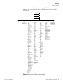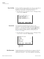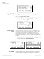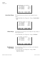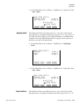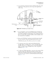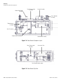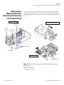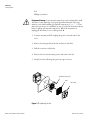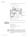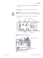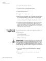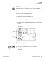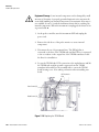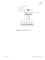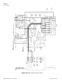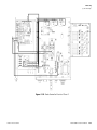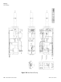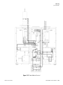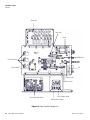
1
Model 3880i Instruction Manual Particulate Matter Continuous Emissions Monitoring System Part Number 112217-00 9Dec2013 © 2013 Thermo Fisher Scientific Inc. All rights reserved. Specifications, terms and pricing are subject to change. Not all products are available in all countries. Please consult your local sales representative for details. Thermo Fisher Scientific Air Quality Instruments 27 Forge Parkway Franklin, MA 02038 1-508-520-0430 www.thermoscientific.com/aqi WEEE Compliance This product is required to comply with the European Union’s Waste Electrical & Electronic Equipment (WEEE) Directive 2002/96/EC. It is marked with the following symbol: Thermo Fisher Scientific has contracted with one or more recycling/disposal companies in each EU Member State, and this product should be disposed of or recycled through them. Further information on Thermo Fisher Scientific’s compliance with these Directives, the recyclers in your country, and information on Thermo Fisher Scientific products which may assist the detection of substances subject to the RoHS Directive are available at: www.thermoscientific.com/WEEERoHS. Thermo Fisher Scientific WEEE Compliance Thermo Fisher Scientific WEEE Compliance About This Manual This manual provides information about installing, maintaining, and servicing the Model 3880i. It also contains important alerts to ensure safe operation and prevent equipment damage. The manual is organized into the following chapters and appendixes to provide direct access to specific operation and service information. Thermo Fisher Scientific ● Chapter 1 “Introduction” provides an overview of the product, describes the theory of operations, and product specifications. ● Chapter 2 “Installation” describes how to install and start up the system. ● Chapter 3 “Operation” describes the front panel display, the front panel pushbuttons, and the menu-driven software. Each menu and submenu is explained. ● Chapter 4 “Calibration” provides an overview on the equipment needed for calibration and a description on how to calibrate the system. ● Chapter 5 “Preventive Maintenance” provides maintenance procedures to ensure reliable and consistent instrument operation. ● Chapter 6 “Troubleshooting” provides guidelines for diagnosing analyzer problems, isolating faults, and includes recommended actions for restoring proper operation. ● Chapter 7 “Servicing” presents safety alerts for technicians working on the analyzer, step-by-step instructions for repairing and replacing components, and a replacement parts list. It also includes contact information for product support and technical information. ● Chapter 8 “System Description” describes the function and location of the system components, provides an overview of the firmware structure, and includes a description of the system electronics and input/output connections. ● Appendix A “Warranty” is a copy of the warranty statement. ● Appendix B “C-Link Protocol Commands” provides a list of C-Link protocol commands that can be used to remotely control an analyzer using a host device such as a PC or datalogger. Model 3880i Instruction Manual i About This Manual Safety ● Safety Safety and Equipment Damage Alerts Appendix C “MODBUS Protocol” provides a description of the MODBUS Protocol Interface and is supported both over RS-232/485 (RTU protocol) as well as TCP/IP over Ethernet. Review the following information carefully before using the probe. This manual provides specific information on how to operate the system, however if the system is used in a manner not specified by the manufacturer, the protection provided by the equipment may be impaired. This manual contains important information to alert you to potential safety hazards and risks of equipment damage. Refer to the following types of alerts you may see in this manual. Safety and Equipment Damage Alert Descriptions Alert Description DANGER A hazard is present that will result in death or serious personal injury if the warning is ignored. ▲ WARNING A hazard is present or an unsafe practice can result in serious personal injury if the warning is ignored. ▲ CAUTION The hazard or unsafe practice could result in minor to moderate personal injury if the warning is ignored. ▲ Equipment Damage The hazard or unsafe practice could result in property damage if the warning is ignored. ▲ Safety and Equipment Damage Alerts in this Manual Alert Description WARNING Pneumatic umbilical must be supported during operations, installation, and removal of probe monitor. ▲ The Model 3880i is supplied with a three-wire grounding cord. Under no circumstances should this grounding system be defeated. ▲ The service procedures in this manual are restricted to qualified service representative. If the equipment is operated in a manner not specified by the manufacturer, the protection provided by the equipment may be impaired. ▲ Pneumatic umbilical must be supported during operations, installation, and removal of probe monitor. ii Model 3880i Instruction Manual Thermo Fisher Scientific About This Manual Safety and Equipment Damage Alerts Alert Description ▲ CAUTION While installing dilution, nozzle and Pitot option, take care not to damage stack temperature sensor sticking out of the mantle cap. ▲ If the LCD panel breaks, do not let the liquid crystal contact your skin or clothes. If the liquid crystal contacts your skin or clothes, wash it off immediately using soap and water. ▲ When loosening or tightening the large VCO sealing nut, you must support the adjoining fittings. ▲ The bypass tee fitting must be held in place with a wrench when either loosening or tightening the large VCO fitting to ensure the bypass tee does not spin. This could cause leaks and possible damage to the bypass thermocouple. ▲ To prevent possible injury, insure hands are clear of the actuators moving parts before applying the pressurized air to the actuator. ▲ All leak testing must be done with a vacuum pump. Pressurizing the TEOM mass transducer can cause damage. ▲ Never pressurize the TEOM mass transducer. ▲ When loosening or tightening the large VCO Sealing Nut, you must support the adjoining “T” fitting on the Heated Bench. ▲ Take CAUTION not to bend the Stack Thermocouple. ▲ Carefully observe the instructions in each procedure. ▲ When removing the top cover, remove the three screws at the front of the cover before loosening or removing screws at the bulkhead. ▲ Equipment Damage Do not attempt to lift the instrument by the cover or other external fittings. ▲ Disconnect the serial cable before changing the RS-232 and RS-485 selection to prevent damage to any equipment currently connected to the analyzer. ▲ Some internal components can be damaged by small amounts of static electricity. A properly grounded antistatic wrist strap must be worn while handling any internal component. If an antistatic wrist strap is not available, be sure to touch the instrument chassis before touching any internal components. When the instrument Thermo Fisher Scientific Model 3880i Instruction Manual iii About This Manual WEEE Symbol Alert Description is unplugged, the chassis is not at earth ground. ▲ It’s important to read all the following steps before replacing the filter. ▲ Do not remove the LCD panel or frame from the LCD module. ▲ The LCD polarizing plate is very fragile, handle it carefully. ▲ Do not wipe the LCD polarizing plate with a dry cloth, as it may easily scratch the plate. ▲ Do not use alcohol, acetone, MEK or other Ketone based or aromatic solvents to clean the LCD module, but rather use a soft cloth moistened with a naphtha cleaning solvent. ▲ Do not place the LCD module near organic solvents or corrosive gases. ▲ Do not shake or jolt the LCD module. ▲ WEEE Symbol The following symbol and description identify the WEEE marking used on the instrument and in the associated documentation. Symbol Description Marking of electrical and electronic equipment which applies to electrical and electronic equipment falling under the Directive 2002/96/EC (WEEE) and the equipment that has been put on the market after 13 August 2005. ▲ iv Model 3880i Instruction Manual Thermo Fisher Scientific About This Manual Where to Get Help Where to Get Help Service is available from exclusive distributors worldwide. Contact one of the phone numbers below for product support and technical information or visit us on the web at www.thermoscientific.com/aqi. 1-866-282-0430 Toll Free 1-508-520-0430 International We continue to support our customers with advanced online resources. Our Air Quality Instruments Online Library allows our customers access to product documents and information on a constant basis. Available 24-hours a day and seven-days a week, the online library provides quick access to information regardless of time zone or office hours. To register for an account or log in, please visit www.thermoscientific.com/aqilibrary. Thermo Fisher Scientific Model 3880i Instruction Manual v About This Manual Where to Get Help vi Model 3880i Instruction Manual Thermo Fisher Scientific Contents Thermo Fisher Scientific Chapter 1 Introduction........................................................................................................ 1-1 Theory of Operation ........................................................................... 1-2 Specifications ...................................................................................... 1-5 Chapter 2 Installation ......................................................................................................... 2-1 Lifting ................................................................................................. 2-1 Unpacking and Inspection .................................................................. 2-2 System Requirements .......................................................................... 2-3 Instrument Installation........................................................................ 2-3 Setup Procedure .................................................................................. 2-4 Probe Monitor Preparation ................................................................. 2-5 Probe Controller ................................................................................. 2-8 Probe Monitor .................................................................................. 2-12 System Startup .................................................................................. 2-15 Mounting the Mantle to Stack .......................................................... 2-17 Chapter 3 Operation ............................................................................................................ 3-1 Display................................................................................................ 3-1 Pushbuttons ........................................................................................ 3-2 Soft Keys.......................................................................................... 3-3 Alphanumeric Entry Screen.............................................................. 3-4 Firmware Overview............................................................................. 3-4 Power-Up Screen ............................................................................. 3-6 Run Screens ..................................................................................... 3-6 Concentration Screen.................................................................... 3-7 Temperatures Screen ..................................................................... 3-8 Pressures Screen ............................................................................ 3-8 Flow Screen................................................................................... 3-9 Neph/TEOM Screen .................................................................... 3-9 Main Menu.................................................................................... 3-10 Averaging Time................................................................................. 3-10 Calibration Factors............................................................................ 3-11 PM Wet Calibration Factors .......................................................... 3-11 PM Wet Calibration Equation ....................................................... 3-11 Reset User Cal Defaults.................................................................. 3-12 Instrument Controls Menu ............................................................... 3-12 Functional Modes .......................................................................... 3-13 Valve Power ................................................................................... 3-13 Set Temperatures ........................................................................... 3-14 Model 3880i Instruction Manual vii Contents Set Temperatures ........................................................................ 3-14 Set Flows........................................................................................ 3-14 Set Flows..................................................................................... 3-15 Set Failsafes .................................................................................... 3-15 Velocity Settings ............................................................................ 3-15 Set Gas........................................................................................ 3-16 External Velocity......................................................................... 3-16 Blow Back Schedule ....................................................................... 3-17 Next Time .................................................................................. 3-17 Period ......................................................................................... 3-17 Mass Mode Schedule...................................................................... 3-18 Next Time .................................................................................. 3-18 System Check Schedule.................................................................. 3-20 Next Time .................................................................................. 3-20 Period ......................................................................................... 3-21 Reset TEOM Total Mass ............................................................... 3-21 Nozzle Select.................................................................................. 3-21 Sample STP ................................................................................... 3-22 Datalogging Settings ...................................................................... 3-22 Select Srec/Lrec ........................................................................... 3-23 View Logged Data....................................................................... 3-23 Number of Records..................................................................... 3-24 Date and Time............................................................................ 3-24 Erase Log .................................................................................... 3-25 Select Content............................................................................. 3-25 Choose Field Data....................................................................... 3-26 Concentrations............................................................................ 3-26 Other Measurements................................................................... 3-26 Analog Inputs.............................................................................. 3-27 Other Measurements 2................................................................ 3-28 Commit Content ........................................................................ 3-28 Reset to Default Content ............................................................ 3-29 Configure Datalogging................................................................ 3-29 Logging Period Min .................................................................... 3-30 Memory Allocation Percent......................................................... 3-30 Data Treatment .......................................................................... 3-30 Flag Status Data .......................................................................... 3-31 Communication Settings................................................................ 3-31 Serial Settings.............................................................................. 3-32 Baud Rate ................................................................................... 3-32 Data Bits ..................................................................................... 3-32 Parity .......................................................................................... 3-33 Stop Bits ..................................................................................... 3-33 RS-232/RS-485 Selection............................................................ 3-33 Instrument ID............................................................................. 3-34 Gesytec Serial Nunber................................................................. 3-34 viii Model 3880i Instruction Manual Thermo Fisher Scientific Contents Communication Protocol............................................................ 3-35 Streaming Data Configuration .................................................... 3-35 Streaming Data Interval .............................................................. 3-36 Select Stream Data ...................................................................... 3-36 Concentrations............................................................................ 3-36 Other Measurements................................................................... 3-37 Other Measurements 2................................................................ 3-38 Analog Inputs.............................................................................. 3-38 TCP/IP Settings.......................................................................... 3-39 Use DHCP ................................................................................. 3-39 IP Address................................................................................... 3-40 Netmask...................................................................................... 3-40 Default Gateway ......................................................................... 3-40 Host Name ................................................................................. 3-41 Network Time Protocol Server.................................................... 3-41 I/O Configuration.......................................................................... 3-41 Output Relay Settings ................................................................. 3-42 Logic State .................................................................................. 3-42 Instrument State ......................................................................... 3-43 Alarms......................................................................................... 3-43 Alarms 2...................................................................................... 3-44 Non-Alarm ................................................................................. 3-45 Digital Input Settings.................................................................. 3-46 Logic State .................................................................................. 3-46 Instrument Action....................................................................... 3-46 Analog Output Configuration (Select Channel) .......................... 3-47 Allow Over/Under Range............................................................ 3-47 Analog Output Configuration (Select Action)............................. 3-48 Select Range ................................................................................ 3-48 Minimum and Maximum Value ................................................. 3-49 Choose Signal to Output ............................................................ 3-51 Analog Input Configuration........................................................ 3-52 Descriptor ................................................................................... 3-53 Units........................................................................................... 3-53 Decimal Places ............................................................................ 3-53 Number of Table Points.............................................................. 3-54 Table Points ................................................................................ 3-54 Volts ........................................................................................... 3-55 User Value .................................................................................. 3-55 Solenoid States ............................................................................... 3-55 Screen Contrast.............................................................................. 3-56 Service Mode ................................................................................. 3-56 Date/Time ..................................................................................... 3-57 Timezone ....................................................................................... 3-57 Diagnostics Menu ............................................................................. 3-58 Program Versions........................................................................... 3-58 Thermo Fisher Scientific Model 3880i Instruction Manual ix Contents Concentrations............................................................................... 3-59 Voltages ......................................................................................... 3-59 Motherboard Voltages................................................................. 3-59 Interface Board Voltages ............................................................. 3-60 I/O Board Voltages ..................................................................... 3-60 Dual Nephelometer Board Voltages ............................................ 3-60 TEOM Board ............................................................................. 3-61 Thermocouple Board Voltages .................................................... 3-61 Temperatures ................................................................................. 3-61 Pressures......................................................................................... 3-62 Flows ............................................................................................. 3-62 Velocity.......................................................................................... 3-63 Nephelometer ................................................................................ 3-63 TEOM Parameters......................................................................... 3-63 System Checks ............................................................................... 3-64 Current System Checks ............................................................... 3-64 Analog Input Readings................................................................... 3-64 Analog Input Voltages.................................................................... 3-65 Digital Inputs................................................................................. 3-65 Relay States .................................................................................... 3-65 Test Analog Outputs...................................................................... 3-66 Set Analog Outputs..................................................................... 3-66 Instrument Configuration .............................................................. 3-67 Contact Information ...................................................................... 3-67 Alarms Menu .................................................................................... 3-67 Concentrations............................................................................... 3-68 PM Wet Conc/PM Dry Conc..................................................... 3-68 PM Factor................................................................................... 3-69 Neph Forward//Neph Fwd Inst/Neph Forward Avg ................... 3-70 TEOM/TEOM Inst/TEOM Avg/Cs Conc................................. 3-70 Temperatures ................................................................................. 3-71 Stack Temperature ...................................................................... 3-72 Dilution Temperature ................................................................. 3-72 Stinger Temperature ................................................................... 3-73 Bypass Temperature .................................................................... 3-74 Neph Block Temperature............................................................ 3-74 Neph Temperature/Neph PCB Temperature .............................. 3-75 TEOM Case Temperature .......................................................... 3-76 TEOM Air Tube Temperature ................................................... 3-76 Probe Control Temperature ........................................................ 3-77 Pressure.......................................................................................... 3-78 Barometric Pressure..................................................................... 3-78 Static Pressure ............................................................................. 3-79 Pitot Pressure .............................................................................. 3-79 TEOM DP Pressure.................................................................... 3-80 Flows ............................................................................................. 3-81 x Model 3880i Instruction Manual Thermo Fisher Scientific Contents Nozzle Flow ................................................................................ 3-81 Dilution Flow/Bypass Flow......................................................... 3-82 Sample Flow/Sample Check Flow ............................................... 3-82 Sample Drift ............................................................................... 3-83 Dilution Ratio Flow .................................................................... 3-84 Nephelometer ................................................................................ 3-84 Neph Source ............................................................................... 3-85 Neph Ref Det ............................................................................. 3-85 Neph Span Source....................................................................... 3-86 Neph Span Ref............................................................................ 3-87 Neph RH.................................................................................... 3-87 Neph Zero Drift ......................................................................... 3-88 Neph Span Drift ......................................................................... 3-89 Neph Fwd Gains......................................................................... 3-89 TEOM........................................................................................... 3-90 TEOM Frequency....................................................................... 3-90 TEOM Std Dev .......................................................................... 3-91 TEOM K0 .................................................................................. 3-92 Total Mass .................................................................................. 3-92 Instrument ..................................................................................... 3-93 Velocity....................................................................................... 3-94 Service Menu .................................................................................... 3-94 Temperature Calibration................................................................ 3-95 Pressure Probe Calibration ............................................................. 3-96 Barometer Pressure Calibration ................................................... 3-96 Calibrate Barometer Pressure Span.............................................. 3-97 Restore Default Calibration......................................................... 3-97 Static Pressure Calibration........................................................... 3-97 Calibrate Static Pressure Zero...................................................... 3-98 Calibrate Static Pressure Span ..................................................... 3-98 Restore Default Calibration......................................................... 3-99 MFC Calibration Pressure/Temperature ........................................ 3-99 Sample MFC Calibration ............................................................... 3-99 Set Sample MFC Calibration .................................................... 3-100 Dilution MFC Calibration........................................................... 3-100 Set Dilution MFC Calibration .................................................. 3-101 Bypass MFC Calibration.............................................................. 3-101 Set Bypass MFC Calibration ..................................................... 3-102 Nephelometer Purge Flow............................................................ 3-102 Nephelometer Calibration............................................................ 3-102 Zero Calibration Values ............................................................ 3-103 Span Calibration Values ............................................................ 3-104 Nephelometer RH..................................................................... 3-105 Nephelometer INT Temperature .............................................. 3-105 Nephelometer Source................................................................ 3-105 Auto Span ................................................................................. 3-106 Thermo Fisher Scientific Model 3880i Instruction Manual xi Contents Analog Output Calibration .......................................................... 3-107 Analog Output Calibrate Zero .................................................. 3-107 Analog Output Calibrate Full-Scale .......................................... 3-108 Analog Input Calibration ............................................................. 3-108 Analog Input Calibrate Zero ..................................................... 3-109 Analog Input Calibrate Full-Scale ............................................. 3-109 Display Pixel Test ........................................................................ 3-110 Restore User Defaults................................................................... 3-110 Restore Factory Defaults .............................................................. 3-110 Password Menu............................................................................... 3-111 Set Password ................................................................................ 3-111 Lock Instrument .......................................................................... 3-112 Lock/Unlock and Local/Remote Operation .............................. 3-112 Change Password ......................................................................... 3-112 Remove Password......................................................................... 3-112 Unlock Instrument....................................................................... 3-113 xii Chapter 4 Calibration ..........................................................................................................4-1 Pressure Sensors .................................................................................. 4-1 Sample MFC....................................................................................... 4-4 Dilution MFC .................................................................................... 4-5 Bypass MFC........................................................................................ 4-6 Nephelometer Purge Flow Calibration ................................................ 4-6 Nephelometer ..................................................................................... 4-7 Zero Cal Values ............................................................................... 4-7 Span Cal Values ............................................................................... 4-7 Neph RH......................................................................................... 4-7 Neph Int Temp................................................................................ 4-7 Neph Source .................................................................................... 4-8 Auto Span ........................................................................................ 4-8 TEOM............................................................................................. 4-8 Chapter 5 Preventive Maintenance .................................................................................5-1 Safety Precautions ............................................................................... 5-1 Preventive Maintenance Schedule ....................................................... 5-2 Fan Filter Inspection and Cleaning ..................................................... 5-3 HEPA Filter Replacement................................................................... 5-4 TEOM Filter Replacement ................................................................. 5-5 Removing a TEOM Filter................................................................ 5-6 Installing a TEOM Filter ................................................................. 5-7 Sample Pump Rebuild ........................................................................ 5-9 O-Ring Replacement......................................................................... 5-11 Bypass Pump Rebuild ....................................................................... 5-14 Sample Line Brush Down ................................................................. 5-17 TEOM Transducer Service ............................................................... 5-20 Model 3880i Instruction Manual Thermo Fisher Scientific Contents Nephelometer Service........................................................................ 5-20 Heated Block Service......................................................................... 5-20 Nozzle and Dilution Module Cleaning ............................................. 5-20 Leak Check ....................................................................................... 5-22 Service Locations............................................................................... 5-39 Thermo Fisher Scientific Chapter 6 Troubleshooting ................................................................................................ 6-1 Safety Precautions ............................................................................... 6-1 Troubleshooting Guides...................................................................... 6-1 Board-Level Connection Diagrams ................................................... 6-10 Connector Pin Descriptions .............................................................. 6-11 PM CEMS Board Diagrams.............................................................. 6-32 Service Locations............................................................................... 6-38 Chapter 7 Servicing............................................................................................................. 7-1 Safety Precautions ............................................................................... 7-3 Firmware Updates ............................................................................... 7-4 Replacement Parts List ........................................................................ 7-4 Cable List............................................................................................ 7-6 External Device Connection Components .......................................... 7-7 Removing the Measurement Case Assembly and Lowering the Partition Panel ................................................................................................. 7-11 Accessing the Service Mode............................................................... 7-13 Fuse Replacement ............................................................................. 7-13 External Pump Replacement ............................................................. 7-13 Fan Replacement............................................................................... 7-13 Internal Pump Replacement.............................................................. 7-15 Mass Flow (Sample) Assembly Replacement ..................................... 7-16 Bypass/Return Mass Flow Assembly Replacement............................. 7-16 Dilution Control Assembly Replacement .......................................... 7-17 Pressure Board Replacement ............................................................. 7-18 Mems Sensor Replacement................................................................ 7-19 SSR Board Replacement.................................................................... 7-20 Pitot Valve Replacement ................................................................... 7-21 DC Power Supply Replacement ........................................................ 7-21 Analog Output Testing ..................................................................... 7-22 Analog Output Calibration ............................................................... 7-24 Analog Input Calibration .................................................................. 7-25 Calibrating the Input Channels to Zero Volts ................................ 7-25 Calibrating the Input Channels to Full-Scale ................................. 7-26 I/O Expansion Board Replacement ................................................... 7-27 Digital Output Board Replacement................................................... 7-29 Motherboard Replacement................................................................ 7-30 Measurement Interface Board Replacement ...................................... 7-31 Front Panel Board Replacement........................................................ 7-32 Model 3880i Instruction Manual xiii Contents LCD Module Replacement ............................................................... 7-33 Nephelometer Replacement .............................................................. 7-34 Heated Bench Replacement .............................................................. 7-36 Valve Manifold Replacement ............................................................ 7-38 TEOM Board Replacement .............................................................. 7-39 Actuator Replacement ....................................................................... 7-41 Sample Control Valve Replacement .................................................. 7-42 DC Power Supply (Monitor) Replacement ....................................... 7-44 Thermocouple Board Replacement ................................................... 7-46 Thermocouple Temperature Probe Calibration................................. 7-48 Mantle Removal................................................................................ 7-50 Dilution Supply Assembly Removal .................................................. 7-52 Sample Line Assembly Removal ........................................................ 7-54 Dilution Thermocouple Removal...................................................... 7-56 Stack Thermocouple Removal........................................................... 7-58 System Drawings............................................................................... 7-60 Service Locations............................................................................... 7-68 Chapter 8 xiv Model 3880i Instruction Manual System Description...........................................................................................8-1 Hardware ............................................................................................ 8-1 Probe Monitor ................................................................................. 8-2 Dilution Nozzle ............................................................................ 8-2 Mantle .......................................................................................... 8-2 Heated Block ................................................................................ 8-2 Nephelometer ............................................................................... 8-3 TEOM.......................................................................................... 8-3 Pneumatic Controls ...................................................................... 8-3 Temperature Control .................................................................... 8-3 Power Supply ................................................................................ 8-3 Probe Controller .............................................................................. 8-3 Dilution MFC .............................................................................. 8-5 Bypass MFC.................................................................................. 8-5 Sample MFC................................................................................. 8-5 Bypass Pump................................................................................. 8-5 Sample Pump................................................................................ 8-5 Pneumatic Umbilical........................................................................ 8-5 Electrical Umbilicals......................................................................... 8-5 Firmware............................................................................................. 8-5 Instrument Control.......................................................................... 8-5 Monitoring Signals........................................................................... 8-6 Measurement Calculations ............................................................... 8-6 Output Communication .................................................................. 8-6 Electronics .......................................................................................... 8-7 Motherboard.................................................................................... 8-7 External Connectors...................................................................... 8-8 Internal Connectors ...................................................................... 8-8 Thermo Fisher Scientific Contents Measurement Interface Board .......................................................... 8-8 Measurement Interface Board Connectors..................................... 8-8 SSR Board........................................................................................ 8-8 Pressure Sensor Assembly ................................................................. 8-9 Digital Output Board....................................................................... 8-9 Front Panel Connector Board .......................................................... 8-9 I/O Expansion Board ....................................................................... 8-9 I/O Components................................................................................. 8-9 Analog Voltage Outputs................................................................. 8-10 Analog Current Outputs ................................................................ 8-10 Analog Voltage Inputs.................................................................... 8-10 Digital Output Relays .................................................................... 8-11 Digital Inputs................................................................................. 8-11 Serial Ports ..................................................................................... 8-11 RS-232 Connection ....................................................................... 8-11 RS-485 Connection ....................................................................... 8-12 Ethernet Connection...................................................................... 8-12 Thermo Fisher Scientific Appendix A Warranty ............................................................................................................ A-1 Appendix B C-Link Protocol Commands............................................................................ B-1 Instrument Identification Number......................................................B-1 Commands .........................................................................................B-1 Commands List................................................................................B-3 Appendix C MODBUS Protocol ............................................................................................C-1 Serial Communication Parameters ..................................................... C-1 TCP Communication Parameters ...................................................... C-2 Application Data Unit Definition ...................................................... C-2 Slave Address................................................................................... C-2 MBAP Header ................................................................................ C-2 Function Code ................................................................................ C-3 Data ................................................................................................ C-3 Error Check .................................................................................... C-3 Function Codes.................................................................................. C-3 (0x01/0x02) Read Coils / Read Inputs ............................................ C-3 (0x03/0x04) Read Holding Registers / Read Input Registers ........... C-5 (0x05) Force (Write) Single Coil..................................................... C-7 MODBUS Parameters Supported ...................................................... C-8 Reading a Write Coil .................................................................... C-13 Model 3880i Instruction Manual xv Contents xvi Model 3880i Instruction Manual Thermo Fisher Scientific Figures Figure 1–1. Model 3880i PM CEMS Flow Schematic........................................ 1-4 Figure 2–1. Remove the Packing Material ......................................................... 2-2 Figure 2–2. Component Layout – Open View of Monitor Assembly ................. 2-3 Figure 2–3. Model 3880i Rear Panel.................................................................. 2-5 Figure 2–4. Probe Monitor with Support Block.................................................. 2-5 Figure 2–5. Probe Mantle Shroud ...................................................................... 2-6 Figure 2–6. Pitot Tube Assembly........................................................................ 2-6 Figure 2–7. Dilution Assembly............................................................................ 2-7 Figure 2–8. Nozzle Assembly.............................................................................. 2-7 Figure 2–9. Push Connect Fitting........................................................................ 2-9 Figure 2–10. System Plumbing 1 ...................................................................... 2-10 Figure 2–11. System Plumbing 2 ...................................................................... 2-11 Figure 2–12. New View of Mantle and Monitor.............................................. 2-12 Figure 2–13. Upper View Probe Monitor (Rear) ............................................... 2-14 Figure 2–14. Lower View of Probe Monitor Connections (Rear) ..................... 2-14 Figure 2–15. TEOM Mounting .......................................................................... 2-15 Figure 2–16. Mantle with Universal Mounting Flange.................................... 2-17 Figure 2–17. Mantle Mount.............................................................................. 2-17 Figure 3–1. Front Panel Display.......................................................................... 3-2 Figure 3–2. Front Panel Pushbuttons.................................................................. 3-2 Figure 3–3. Flowchart of Menu-Driven Firmware .............................................. 3-5 Figure 4–1. Nephelometer Calibration Diagram ................................................ 4-3 Figure 4–2. TEOM Calibration Diagram ............................................................. 4-4 Figure 5–1. Inspecting and Cleaning the Fan Filters.......................................... 5-3 Figure 5–2. Replacing the TEOM Filter .............................................................. 5-6 Figure 5–3. Filter Tool......................................................................................... 5-6 Figure 5–4. Removing the TEOM Filter with the Filter Tool .............................. 5-6 Figure 5–5. Removing the TE Filter .................................................................... 5-7 Figure 5–6. Filter Tool with Clean Filter............................................................. 5-7 Figure 5–7. Empty Mass Transducer with Filter Change Notch ........................ 5-8 Figure 5–8. Placing the FIlter on the Post .......................................................... 5-8 Figure 5–9. Back of Filter Exchange Tool ........................................................... 5-8 Figure 5–10. Setting the Filter............................................................................ 5-8 Figure 5–11. Rebuilding the Sample Pump ...................................................... 5-10 Figure 5–12. Replacing the Heated Bench External O-Rings........................... 5-11 Thermo Fisher Scientific Model 3880i Instruction Manual xvii Figures Figure 5–13. VCO Sealing Nut and “T” Fitting .................................................5-12 Figure 5–14. Nephelometer/Sample Adapter ..................................................5-12 Figure 5–15. TEOM Mounting Assembly Cutaway ..........................................5-13 Figure 5–16. TEOM Mounting Lever and Cap Top View ..................................5-14 Figure 5–17. Rebuilding the Bypass Pump .......................................................5-16 Figure 5–18. Sample Line Brush Down.............................................................5-18 Figure 5–19. Thermocouple Side View.............................................................5-19 Figure 5–20. Brush Down Sample Line.............................................................5-20 Figure 5–21. Hand Vacuum Pump.....................................................................5-23 Figure 5–22. Sample In .....................................................................................5-24 Figure 5–23. Dilution 1 and 2............................................................................5-25 Figure 5–24. Bypass ..........................................................................................5-25 Figure 5–25. Rear View of the Probe Monitor..................................................5-26 Figure 5–26. Bypass “T” Fitting – Large VCO Cap ...........................................5-27 Figure 5–27. Nephelometer Inlet and Neph/Sample Adapter VCO Caps........5-28 Figure 5–28. Nephelometer Outlet with Adapter Fitting .................................5-29 Figure 5–29. Sample Line Connection to Heated Air Tube ..............................5-30 Figure 5–30. Sample Line Connection with Capped Air Tube – Blind VCO Plug......................................................................................................................5-31 Figure 5–31. TEOM Sample Port.......................................................................5-32 Figure 5–32. TEOM Sample Port Isolated from Sample Valve and Filter ........5-33 Figure 5–33. Top View of TEOM Sample Inlet .................................................5-34 Figure 5–34. O-Ring Locations of the TEOM Mounting Assembly ..................5-35 Figure 5–35. Isolation of the Front Half of the Heated Bench Assembly ........5-36 Figure 5–36. Isolated Dilution Assembly of the Mantle ..................................5-37 Figure 5–37. Isolated Stinger/Sample Assembly of the Mantle .....................5-38 Figure 5–38. Mantle Cap View .........................................................................5-39 Figure 6–1. Board-Level Connection Diagram ..................................................6-10 Figure 6–2. Board-Level Connection Diagram – Measurement Interface .......6-32 Figure 6–3. Board-Level Connection Diagram - Probe Temperature Controller.............................................................................................................6-33 Figure 6–4. Board-Level Connection Diagram – TEOM Head Controller.........6-33 Figure 6–5. Board-Level Connection Diagram – SSR Driver ............................6-34 Figure 7–1. Properly Grounded Antistatic Wrist Strap.......................................7-4 Figure 7–2. Probe Controller Component Layout Top View ...............................7-8 Figure 7–3. Probe Controller Component Layout Panel Down ...........................7-9 Figure 7–4. Probe Monitor Component Layout.................................................7-10 Figure 7–5. Probe Monitor Top View................................................................7-10 Figure 7–6. Removing the Measurement Case Assembly and Lowering the Partition Panel.....................................................................................................7-11 Figure 7–7. Replacing the Fan ..........................................................................7-14 xviii Model 3880i Instruction Manual Thermo Fisher Scientific Figures Figure 7–8. Replacing the Internal Pump ......................................................... 7-15 Figure 7–9. Replacing the DC Power Supply.................................................... 7-22 Figure 7–10. Rear Panel Analog Input and Output Pins................................... 7-23 Figure 7–11. Replacing the I/O Expansion Board............................................. 7-28 Figure 7–12. Rear Panel Board Connectors...................................................... 7-29 Figure 7–13. Replacing the Front Panel Board and the LCD Module .............. 7-33 Figure 7–14. Replacing the Nephelometer ...................................................... 7-35 Figure 7–15. Nephelometer Connections......................................................... 7-36 Figure 7–16. Heated Bench Upside-Down View.............................................. 7-37 Figure 7–17. Heated Bench Removed .............................................................. 7-37 Figure 7–18. Replacing the Valve Manifold..................................................... 7-39 Figure 7–19. Replacing the TEOM Board ......................................................... 7-40 Figure 7–20. Removing the Actuator Assembly............................................... 7-42 Figure 7–21. Replacing the Sample Control Valve........................................... 7-43 Figure 7–22. Removing DC Power Supply Cover.............................................. 7-45 Figure 7–23. Thermocouple/Power Supply Assembly Top View..................... 7-45 Figure 7–24. Thermocouple/Power Supply Bottom View................................ 7-46 Figure 7–25. Removing the Thermocouple Board Cover.................................. 7-47 Figure 7–26. Thermocouple Board Assembly................................................... 7-47 Figure 7–27. Thermocouple Placement............................................................ 7-50 Figure 7–28. Removing the Mantle Assembly ................................................. 7-51 Figure 7–29. Mantle Cap Assembly with Connections.................................... 7-54 Figure 7–30. Stack Thermocouple Length........................................................ 7-59 Figure 7–31. Probe Controller Plumbing Sheet 1 ............................................. 7-61 Figure 7–32. Probe Controller Plumbing Sheet 2 ............................................. 7-62 Figure 7–33. Probe Controller Plumbing Sheet 3 ............................................. 7-63 Figure 7–34. Probe Controller Electrical Sheet 1 ............................................. 7-64 Figure 7–35. Probe Controller Electrical Sheet 2 ............................................. 7-65 Figure 7–36. Probe Monitor Plumbing.............................................................. 7-66 Figure 7–37. Probe Monitor Electrical.............................................................. 7-67 Figure 8–1. Probe Monitor Hardware Components ........................................... 8-2 Figure 8–2. Probe Controller Components ......................................................... 8-4 Thermo Fisher Scientific Model 3880i Instruction Manual xix Figures xx Model 3880i Instruction Manual Thermo Fisher Scientific Tables Table 1–1. Model 3880i PM CEMS Specifications............................................ 1-5 Table 3–1. Front Panel Pushbuttons................................................................... 3-3 Table 3–2. Analog Output Zero to Full-Scale ................................................... 3-49 Table 3–3. Signal Type Group Choices............................................................. 3-51 Table 5–1. Preventive Maintenance Schedule................................................... 5-2 Table 6–1. Troubleshooting – General Guide .................................................... 6-2 Table 6–2. Troubleshooting – Probe Controller ................................................. 6-3 Table 6–3. Troubleshooting – Instrument Alarms.............................................. 6-5 Table 6–4. Troubleshooting – Power-Thermocouple Assembly ........................ 6-6 Table 6–5. Troubleshooting – Nephelometer .................................................... 6-8 Table 6–6. Troubleshooting – TEOM.................................................................. 6-8 Table 6–7. Motherboard Connector Pin Descriptions...................................... 6-11 Table 6–8. I/O Expansion Board Connector Pin Descriptions .......................... 6-18 Table 6–9. Digital Output Board Connector Pin Descriptions.......................... 6-19 Table 6–10. Measurement Interface Board Connector Pin Descriptions ........ 6-21 Table 6–11. 146i Connector Board Connector Pin Descriptions...................... 6-25 Table 6–12. AC Distribution Board Connector Pin Descriptions...................... 6-25 Table 6–13. Probe Temperature Control Board Connector Pin Descriptions... 6-26 Table 6–14. TEOM Head Controller Board Connector Pin Descriptions.......... 6-27 Table 6–15. SSR Driver Board Connector Pin Descriptions ............................. 6-28 Table 6–16. Dichot NEPH MIB Connector Pin Descriptions............................. 6-30 Table 6–17. MIB Status LEDs ........................................................................... 6-34 Table 6–18. MIB Test Points............................................................................. 6-34 Table 6–19. SSR Driver Board Status LEDs...................................................... 6-35 Table 6–20. SSR Board Fuses........................................................................... 6-36 Table 6–21. Probe Temp Controller Board Status LEDs................................... 6-36 Table 6–22. Probe Temp Controller Board Fuses ............................................. 6-37 Table 6–23. Probe Temp Controller Board Test Points .................................... 6-37 Table 6–24. TEOM Head Controller Board Status LEDs .................................. 6-37 Table 6–25. TEOM Head Controller Board Fuses............................................. 6-37 Table 6–26. TEOM Head Controller Board Test Points.................................... 6-37 Table 7–1. Model 3880i Replacement Parts...................................................... 7-4 Table 7–2. Model 3880i Cables.......................................................................... 7-6 Table 7–3. External Device Connection Components ........................................ 7-7 Table 7–4. Analog Output Channels and Rear Panel Pin Connections............ 7-24 Thermo Fisher Scientific Model 3880i Instruction Manual xxi Tables Table 7–5. Analog Input Channels and Rear Panel Pin Connections...............7-27 Table 8–1. RS-232 DB9 Connector Pin Configurations.....................................8-12 Table 8–2. RS-485 DB9 Connector Pin Configuration ......................................8-12 Table B–1. Error Response Messages................................................................B-2 Table B–2. C-Link Protocol Commands...............................................................B-3 Table C–1. Read Coils for 3880i .........................................................................C-8 Table C–2. Read Registers for 3880i................................................................C-11 Table C–3. Write Coils for 3880i ......................................................................C-13 xxii Model 3880i Instruction Manual Thermo Fisher Scientific Chapter 1 Introduction The Thermo Scientific™ Model 3880i Particulate Matter Continuous Emissions Monitoring System (PM CEMS) is designed to extract, dilute, and transport a flue gas sample for the measurement of a wet-based filterable particulate matter concentration. The system is comprised of a Model 3880i Probe Controller and a Probe Monitor, along with optional peripheral components, such as a zero air supply, freeze protected umbilical, and probe controller enclosure. For details of the instrument’s theory of operation and product specifications, see the following topics: ● “Theory of Operation” on page 1-2 ● “Specifications” on page 1-5 Thermo Fisher Scientific is pleased to supply this Model 3880i. We are committed to the manufacture of instruments exhibiting high standards of quality, performance, and workmanship. Service personnel are available for assistance with any questions or problems that may arise in the use of this instrument. For more information on servicing, see the “Servicing” chapter starting on page 7-1. Thermo Fisher Scientific Model 3880i Instruction Manual 1-1 Introduction Theory of Operation Theory of Operation The Model 3880i is based on two methods of particulate mass detection. These methods are light scattering and inertial weighing. The continuous measurement of particulate mass is through the use of elastic light scattering. In the presence of light, particulate matter is known to scatter light in all directions. The intensity by which light is scattered in the presence of an incident beam of light is given by: R= I0N Cm ∫∫∫ f (d p ) λ2 (i1 + i2 ) f (λ )F (θ )dd p dλdθ 8π 2 r 2 where: R = scattered light Io = incident illumination irradiance N = particle number concentration Cm = mass concentration f(dp) = size distribution function λ = wavelength of illuminating source r = distance to detector from particle scattering light i1, i2 = Lonenz-Mie scattering intensity functions f(λ) = source/detector wavelength dependence F(θ) = angular scattering geometry of optical system While the detection of particulate with this method can offer an extensive dynamic range and rapid response, the multitude of parameters listed above can significantly influence the accuracy. Therefore, a continuous internal mass reference is used to scale the light scattering response. The primary method of mass measurement is an inertial weighing technology based on measuring the frequency of vibration of a tapered element oscillating microbalance (TEOM). The tapered element is a hollow tube, clamped at one end and free to vibrate at the other. An exchangeable filter accumulates the particulate mass that is drawn as a collected sample. During sample collection, this tapered element vibrates precisely at its natural resonant frequency through the assistance of electronic controls. A precise electronic counter measures the frequency, which has a direct relationship with mass. 1-2 Model 3880i Instruction Manual Thermo Fisher Scientific Introduction Theory of Operation Specifically, f 2 = K0 m where: f = frequency of oscillation K0 = calibration constant m = mass By arranging the above relationship into discrete time, the change in mass (Δm) can be measured between two separate frequencies (f1, f2) by the following: ⎡ 1 ⎤ ⎡ 1 ⎤ Δm = K 0 ⎢ 2 ⎥ − ⎢ 2 ⎥ ⎣ f 2 ⎦ ⎣ f1 ⎦ By measuring the change in sample volume, passing through the TEOM, and the mass (as shown above) the mass concentration can be calculated as follows: C PM = Δm ΔV where: CPM = particulate matter concentration Δm = change in particulate mass ΔV = change in air volume It is the periodic use of the TEOM as an internal particulate mass reference that applies a correction factor (PM factor) to the light scattering response to calculate a final concentration, PMwet. The Model 3880i PM CEMS predominately operates in a functional mode called Monitor mode (Figure 1–1). During this period a slip-stream of the diluted sample passes through the forward light scattering assembly; whereby the PM factor is applied as follows to the forward light scatter signal (FWD). PMwet = PMfactor x FWD Thermo Fisher Scientific Model 3880i Instruction Manual 1-3 Introduction Theory of Operation The PMfactor is simply derived from a different functional mode referenced as the Mass Mode. During this period the same slip-stream passes through both the light scattering assembly and the Tapered Element Oscillating Microbalance (TEOM) for a specified duration (e.g., 2-3 hours). At the end of this Mass Mode the average FWD and TEOM are used to update the PM factor as follows: PMfactor = TEOMavg. FWDavg. Figure 1–1. Model 3880i PM CEMS Flow Schematic The relationship of frequency to mass is direct, as stated above. The TEOM system measures frequency. As the mass of this system changes, so too does the frequency. However, no matter what the particulate mass characteristics may be (i.e., size, shape, refractive index, or chemical composition) the accuracy of measurement remains. 1-4 Model 3880i Instruction Manual Thermo Fisher Scientific Introduction Specifications Specifications Table 1–1 lists the standard specifications for the Model 3880i PM CEMS. Table 1–1. Model 3880i PM CEMS Specifications Thermo Fisher Scientific Item Description Power requirements 200–240 VAC @ 50/60 Hz, ~30 amp service Clean dry air 80 slpm @ 75–100 psi Flange adapter 4” Universal mounting flange IP rating IP6_on probe enclosure @ stack Probe monitor dimensions 44.01” W x 18.69” H x 12.09” D (111.8cm W x 47.47cm H x 30.71cm D) Probe monitor weight 130 lbs (58.97 kg) Probe controller dimensions 19.0” W x 8.62” H x 25.8” D (48.26cm W x 21.89cm H x 65.53cm D) Probe controller weight 55 lbs (24.95 kg) Probe lengths 36” L (91.44cm L) 60” L (152.4cm L) Probe material 316 SS (coating available upon request) Mantle material Hastelloy, Stainless, or PFA coated Enclosure options Standard 19-in rack (custom umbilical required) Weather enclosure at flange (available upon request) Umbilical options Cold pneumatics with freeze protect flying leads 25-ft standard length with weather enclosure Custom length available upon request with 19-in rack Range 0–250 mg/m3 Accuracy ±20% without source correlation ±10% with source correlation Detection limit 0.25 mg/m3 @ 15-minute integration time Response time 15 minutes to 90% of value Maximum stack temperature 200 °C (higher available upon request) Flue gas ≤ 20% moisture (higher available upon request) Velocity range 4–20 m/s (13.12–65.62 ft/sec) System temperature range 4–50 °C; non-condensing for 19-in rack mounted probe controller Analog outputs 6 voltage outputs; 0–100 mV, 1, 5, 10 V (user selectable), 5% of full-scale over/under range (user selectable), 12 bit resolution, measurement output user selectable per channel Model 3880i Instruction Manual 1-5 Introduction Specifications Item Description 6 current outputs firmware configured for any one of the following ranges, while maintaining a minimum resolution of 11 bits: 0-20 mA, 4-20 mA 1-6 Model 3880i Instruction Manual Digital outputs 1 power fail relay Form C, 10 digital relays Form A, user selectable alarm output, relay logic, 100 mA @ 200 VDC Digital inputs 16 digital inputs, user select programmable, TTL level, pulled high Serial ports 1 RS-232 or RS-485 with two connectors, baud rate 1200–115200, data bits, parity, and stop bits, protocols: C-Link, MODBUS, and streaming data (all user selectable) Ethernet connection RJ45 connector for 10Mbs Ethernet connection, static or dynamic TCP/IP addressing Thermo Fisher Scientific Chapter 2 Installation Installation of the Model 3880i PM CEMS includes lifting the instrument, unpacking and inspection, connecting sample, zero, span, and exhaust lines, and attaching the analog outputs to a recording device. The installation should always be followed by instrument calibration as described in the “Calibration” chapter of this manual. This chapter provides the following recommendations and procedures for installing the instrument: Lifting ● “Lifting” on page 2-1 ● “Unpacking and Inspection” on page 2-2 ● “System Requirements” on page 2-3 ● “Instrument Installation” on page 2-3 ● “Setup Procedure” on page 2-4 ● “Probe Monitor Preparation” on page 2-5 ● “Probe Controller” on page 2-8 ● “Probe Monitor” on page 2-12 ● “System Startup” on page 2-15 ● “Mounting the Mantle to Stack” on page 2-17 When lifting the instrument, use a procedure appropriate for lifting a heavy object, such as, bending at the knees while keeping your back straight and upright. Grasp the instrument at the bottom in the front and at the rear of the unit. Although one person can lift the unit, it is desirable to have two persons lifting, one by grasping the bottom in the front and the other by grasping the bottom in the rear. Equipment Damage Do not attempt to lift the instrument by the cover or other external fittings. ▲ Thermo Fisher Scientific Model 3880i Instruction Manual 2-1 Installation Unpacking and Inspection Unpacking and Inspection Depending on the intended use, the Model 3880i is shipped complete in two containers. One container includes the 3880i probe controller; the other container includes the vacuum pump. Note When unpacking the pump, save the instruction manual that came with the pump for future reference. ▲ If there is obvious damage to the shipping container(s) when you receive the instrument, notify the carrier immediately and hold for inspection. The carrier is responsible for any damage incurred during shipment. Use the following procedure to unpack and inspect the instrument. 1. Remove the instrument from the shipping container and set it on a table or bench that allows easy access to both the front and rear. 2. Remove the cover to expose the internal components. 3. Remove the packing material (Figure 2–1). Remove Packing (2 pieces) Figure 2–1. Remove the Packing Material 4. Check for possible damage during shipment. 5. Check that all connectors and circuit boards are firmly attached. 6. Remove shipping screws from sample pump. 2-2 Model 3880i Instruction Manual Thermo Fisher Scientific Installation System Requirements 7. Re-install the cover. System Requirements Voltage = 200V–240V 50/60 Hz AC Clean Dry Air (CDA) Particulate free with a dew point of -40 °C or less 80–100 psi with a flow capacity ≥80 slpm Zero Air Particulate free 80–100 psi with a flow capacity ≥80 slpm (slpm: standard liters per minute @ 25 °C, 1 atm) Instrument Installation Ensure that the instrument is connected to the air supply using the support umbilical, noting all labels to ensure proper connection. WARNING Pneumatic umbilical must be supported during operations, installation, and removal of probe monitor. ▲ Blow out the pneumatic umbilicals with clean dry air before installing. Connect the freeze protected umbilical to both the probe and the instrument (connector side goes toward the instrument chassis). Ensure that the umbilical is (properly strain relieved) on the outside of the instrument to prevent excessive strain on the monitor assembly. Figure 2–2. Component Layout – Open View of Monitor Assembly Thermo Fisher Scientific Model 3880i Instruction Manual 2-3 Installation Setup Procedure Setup Procedure The Model 3880i is capable of measuring filterable particulate matter from laboratory generated aerosol or as emitted from a coal-fired boiler, incinerator, or cement kiln. The procedure for setting up the Model 3880i will only vary with regard to probe length, probe controller mounting, and umbilical length logistics. Be sure to review the air and power supply requirements before install. The Model 3880i is comprised of the following major assemblies: 1. Probe Mantle 2. Probe Monitor Enclosure 3. Umbilical (Pneumatic bundle and 2 electrical) 4. Probe Controller 5. Pump Assembly Please note that the Probe Mantle is shipped connected to the Probe Monitor Enclosure. Depending upon the site specifics, the Probe Mantle can be removed from the Probe Monitor Enclosure and installed sequentially pending space constraints at the point of installation. Refer to “Mantle Removal” on page 7-50 in the Servicing section for removal and connecting mantle to probe monitor. When installing, always make connectors to the Probe Controller first. WARNING The Model 3880i is supplied with a three-wire grounding cord. Under no circumstances should this grounding system be defeated. ▲ 2-4 Model 3880i Instruction Manual Thermo Fisher Scientific Installation Probe Monitor Preparation Push Connect Fittings CDA-Clean Dry Air Figure 2–3. Model 3880i Rear Panel Probe Monitor Preparation Use the following procedure to prepare the probe monitor. WARNING The Model 3880i is supplied with a three-wire grounding cord. Under no circumstances should this grounding system be defeated. ▲ 1. On bench on floor, place probe monitor with support block under the mantle (Figure 2–4). Support Block Figure 2–4. Probe Monitor with Support Block 2. Remove the six hex screws from the mantle shroud. Save screws for reinstallation (Figure 2–5). Thermo Fisher Scientific Model 3880i Instruction Manual 2-5 Installation Probe Monitor Preparation Figure 2–5. Probe Mantle Shroud 3. If Pitot option ordered, remove 3 protective caps on Pitot fittings. Add silver goop to threads of Pitot fittings before installing Pitot tube assembly (Figure 2–6). Add Silver Goop to Fitting Threads Pitot Tube Assembly Figure 2–6. Pitot Tube Assembly 4. Install dilution assembly on to mantle cap. Aligning both the ½-inch port and dilution air supply line. Push with a slight twist to seat over the sealing 0-rings. Once in place, tighten 1/4 dilution air line. Then tighten the three set screw to secure dilution assemble to mantle cap (Figure 2–7). 2-6 Model 3880i Instruction Manual Thermo Fisher Scientific Installation Probe Monitor Preparation Dilution Air Line Mantle Cap Dilution Assembly Set Screws (3) Figure 2–7. Dilution Assembly 5. Install nozzle into dilution assembly. Position nozzle tip pointing down, seat and tighten (Figure 2–8). Top Dilution Assembly Bottom Nozzle Figure 2–8. Nozzle Assembly CAUTION While installing dilution, nozzle and Pitot option, take care not to damage stack temperature sensor sticking out of the mantle cap. ▲ 6. Reinstall mantle shroud in reverse order. Add silver goop to screw threads before installing. Note Do not over tighten screws which could result in damaging shroud. (need tightness spec). ▲ Thermo Fisher Scientific Model 3880i Instruction Manual 2-7 Installation Probe Controller Probe Controller Use the following procedure to install the Model 3880i PM CEMS Probe Controller in an emissions monitoring application. (Refer to Figure 2–10 and Figure 2–11 for System Plumbing.) 1. Connect the 3/8-inch house zero air input line to the rear panel port labeled ZERO AIR. The pressure input should be 80–100 psi @ 80 slpm. 2. Connect the 3/8-inch house clean dry air to the rear panel port labeled CDA. This port has a T-fitting already mounted to the rear panel. The pressure input should be 80–100 psi @ 80 slpm. 3. From the umbilical, connect the 3/8-inch tube labeled DIL1 to the rear panel port labeled DIL1. 4. From the umbilical, connect the 3/8-inch tube labeled DIL2 to the rear panel port labeled DIL2. 5. From the umbilical side labeled “to probe cntrl”, connect the 3/8-inch tube labeled BYPASS to the rear panel port labeled BYPASS IN. 6. From the umbilical, connect the 1/4-inch tube labeled SAMPLE IN to the sample relief valve assembly rear panel port labeled SAMPLE IN. 7. From the umbilical, connect a spare 1/4-inch tube labeled SAMPLE OUT and vent to atmosphere (outside of CEMS shelter). 8. Using Figure 2-4, connect the labeled 1/8-inch tubes into the push-toconnect fitting. This fitting is keyed and can now be connected to the rear panel. 2-8 Model 3880i Instruction Manual Thermo Fisher Scientific Installation Probe Controller Figure 2–9. Push Connect Fitting 9. With tubing assembly (BYPASS OUT/RETURN to pump intake) of 3/8-inch tubing, connect the rear panel port labeled BYPASS OUT/RETURN to the intake port of the 220 VAC vacuum pump provided. 10. From the umbilical, connect the 3/8-inch tube labeled RETURN to the outlet of vacuum pump. 11. Connect the keyed electrical umbilical to the rear panel connector labeled RS485/HEAT, and connect the grounding strap to the rear panel ground lug. 12. Connect the keyed electrical umbilical to the rear panel connector labeled VALVES/POWER, and connect the grounding strap to the rear panel ground lug. 13. Connect a suitable recording device to the rear panel connector. See “Instrument Controls” > “I/O Configuration” in the “Operations” chapter for more information about the rear panel pin-out. 14. Plug the probe controller into an outlet of the appropriate voltage and frequency. Thermo Fisher Scientific Model 3880i Instruction Manual 2-9 Installation Probe Controller Figure 2–10. System Plumbing 1 2-10 Model 3880i Instruction Manual Thermo Fisher Scientific Installation Probe Controller Figure 2–11. System Plumbing 2 Thermo Fisher Scientific Model 3880i Instruction Manual 2-11 Installation Probe Monitor Probe Monitor Use the following procedure to install the Model 3880i PM CEMS probe monitor. (Refer to Figure 2–10 for System Plumbing on page 2-10.) 1. On a bench or floor, taking care not to damage the nozzle and dilution module (remove if necessary), line the mantle up with probe enclosure with 3/4-inch fitting in 12 o’clock position. Mantle Bolts (4) Figure 2–12. New View of Mantle and Monitor 2. Bolt mantle in place with four 5/8-inch-11 x 1 1/2-inch bolts and split lock washers. Note If there is sufficient space, the probe monitor with the mantle connected should be arranged near the monitoring port. If some instances, the mantle may have to be inserted first and the probe monitor enclosure added next. ▲ 3. From the umbilical side labeled “to probe monitor”, connect the 3/8inch tubing labeled CDA to the upper rear panel of the probe monitor. 2-12 Model 3880i Instruction Manual Thermo Fisher Scientific Installation Probe Monitor 4. Connect the 1/4-inch umbilical tubing labeled SAMPLE to the upper rear panel of the probe monitor. 5. Connect the three 1/8-inch umbilical tubes labeled Pd, Ps, and Pi to the upper rear panel of the probe monitor. 6. Connect the 3/8-inch umbilical tube labeled BYPASS to the large HEPA filter provided, and connect the other end of the HEPA to the lower rear panel labeled BYPASS of the probe monitor. 7. Connect the 3/8-inch umbilical tube labeled RETURN to the lower rear panel of the probe monitor. 8. Connect the 3/8-inch umbilical tube labeled DIL1 to the lower rear panel of the probe monitor. 9. Connect the 3/8-inch umbilical tube labeled DIL2 to the lower rear panel of the probe monitor. 10. Connect the 1/8-inch umbilical tube labeled PURGE to the lower rear panel of the probe monitor. 11. Connect the keyed electrical umbilical to the upper rear panel of the probe monitor labeled RS485/HEAT and connect the grounding strap to the rear panel ground lug. 12. Connect the keyed electrical umbilical to the upper rear panel of the probe monitor labeled VALVES/POWER. Thermo Fisher Scientific Model 3880i Instruction Manual 2-13 Installation Probe Monitor Figure 2–13. Upper View Probe Monitor (Rear) Figure 2–14. Lower View of Probe Monitor Connections (Rear) 2-14 Model 3880i Instruction Manual Thermo Fisher Scientific Installation System Startup System Startup Use the following procedure when starting the instrument. 1. Check rear compartment of the probe monitor to be sure a TEOM module has been installed and the release lever is pushed firmly to the left (Figure 2–15). Install and Release Lever Figure 2–15. TEOM Mounting 2. Check condition of the sampling nozzle and dilution fittings. If the system has been shipped or located to the monitoring port with the nozzle assembly removed, locate the assembly, slide over the 1/2-inch sample tube at the mantle inlet and secure the dilution air fittings to the available 14-inch port. 3. Confirm adequate zero air and CDA are provided. 4. Power the system ON. 5. Place system into a Purge mode, using “Instrument Controls” > “Functional Mode”. Thermo Fisher Scientific Model 3880i Instruction Manual 2-15 Installation System Startup 6. From Main Menu, choose “Instrument Controls” > “Set Flows” and verify the following flow settings: Both Dilution and Bypass=21.0 slpm, and Sample=2.5 slpm. Purge flow will have been calibrated in the factory and is approximately 0.4 slpm. 7. With the system in Purge mode, the dilution air will automatically increase to 3-4 slpm above the set point. This will result in a positive flow leaving the nozzle. 8. With the system in Monitor mode, test the flow using a reference flow meter measuring standard liters per minute (@760 mmHg, 25 deg C), measure the flow output of the nozzle. The measured flow should equal the nozzle flow (appearing negative under “Diagnostics” > “Flows”), within 0.2 slpm. If this is out of tolerance, check for leaks. Refer to “Leak Check” on page 5-22. 9. Set the system temperatures as follows: Dilution=165 °C (wet stack), 120 °C (dry stack) Stinger=120 °C Block=100 °C Nephelometer=58 °C TEOM air tube=62 °C TEOM case=65 °C 10. After system comes to temperature, place system into Monitor mode and measure flow entering the nozzle. The nozzle flow displayed on the “Diagnostics” > “Flows” screen should match the flow measured by the reference flow meter within ±0.2 slpm. If not, refer to “Leak Check” on page 5-22. 11. The system may now be inserted into the monitoring location and secured to the flange. Place system in Purge mode and set all temperatures to zero. Let cool then install. 2-16 Model 3880i Instruction Manual Thermo Fisher Scientific Installation Mounting the Mantle to Stack Mounting the Mantle to Stack Depending on work area, manpower, and other site-specific criteria, you may opt to install the mantle and probe at once, or the mantle first, and then the probe. Use the following procedure to mount the mantle to stack. Align mantle thru holes (Figure 2–16) to stack sample port thru holes, so probe is in desired position. Refer to Figure 2–17 and install hardware in four places. Figure 2–16. Mantle with Universal Mounting Flange Figure 2–17. Mantle Mount Thermo Fisher Scientific Model 3880i Instruction Manual 2-17 Chapter 3 Operation This chapter describes the front panel display screens, front panel pushbuttons, and menu-driven firmware. For details, see the following topics: Display Thermo Fisher Scientific ● “Display” on page 3-1 ● “Pushbuttons” on page 3-2 ● “Firmware Overview” on page 3-4 ● “Averaging Time” on page 3-10 ● “Calibration Factors” on page 3-11 ● “Instrument Controls Menu” on page 3-12 ● “Diagnostics Menu” on page 3-57 ● “Alarms Menu” on page 3-67 ● “Service Menu” on page 3-94 ● “Password Menu” on page 3-111 The 320 x 240 graphics liquid-crystal display (LCD) shows the sample concentrations, instrument parameters, instrument controls, help, and error messages. Some menus contain more items than can be displayed at one time. For these menus, use and to move the cursor up and down to each item. Model 3880i Instruction Manual 3-1 Operation Pushbuttons Figure 3–1. Front Panel Display CAUTION If the LCD panel breaks, do not let the liquid crystal contact your skin or clothes. If the liquid crystal contacts your skin or clothes, wash it off immediately using soap and water. ▲ Pushbuttons The Pushbuttons allow the user to traverse the various screens/menus. Figure 3–2. Front Panel Pushbuttons 3-2 Model 3880i Instruction Manual Thermo Fisher Scientific Operation Pushbuttons Table 3–1 lists the front panel pushbuttons and their functions. Table 3–1. Front Panel Pushbuttons Key Name Function = Soft Keys The (soft keys) are used to provide shortcuts that allow the user to jump to user-selectable menu screens. For more information on processing soft keys, see “Soft Keys” below. = Run is used to display the Run screen. The Run The screen normally displays the current PM concentrations, but also has additional Run screens for ambient conditions, sample conditions, and mass sensor data. Press and to scroll through the different Run screens. = Menu The is used to display the Main Menu when in the Run screen, or back up one level in the menu system. For more information about the Main Menu, see “Main Menu” later in this chapter. = Help The is context-sensitive, that is, it provides additional information about the screen that is being displayed. Press for a brief explanation about the current screen or menu. Help messages are displayed using lower case letters to easily distinguish them from the operating screens. Press to return to the Run screen, or any other key to exit a help screen. = Up, Down = Left, Right = Enter Soft Keys , , , and The four arrow pushbuttons ( ) move the cursor up, down, left, and right or change values and states in specific screens. The is used to select a menu item, accept/set/save a change, and/or toggle on/off functions. The soft keys are multi-functional keys that use part of the display to identify their function. The function of the soft keys is to provide a shortcut to the most often used menus and screens. They are located directly underneath the display, and user-defined labels in the lower part of the display indicate the function of each key at that time. To change a soft key, place the menu cursor “>” on the item of the selected menu or screen you wish to set. Press followed by the selected soft key within 1 second of pressing the right-arrow key. The “edit soft key prompt” will be displayed for configuration of the new label. Note Not all menu items may be assigned to soft keys. If a particular menu or screen item cannot be assigned, the key assignment screen will not come up upon entering right-arrow-soft key combinations. All items under the Service menu (including the menu itself) cannot be assigned soft keys. ▲ Thermo Fisher Scientific Model 3880i Instruction Manual 3-3 Operation Firmware Overview EDIT SOFT KEY PROMPT: CURRENTLY: RANGE RANGE ABCDEFGHIJKLMN BKSP OPQRSTUVWXYZ PAGE 0123456789 ./- SAVE CFACT INST DIAGS ALARM Programmable Soft Key Labels Alphanumeric Entry Screen The alphanumeric entry screen is used to enter strings consisting of letters, numbers, and other characters. The cursor may be positioned within the and keys. If a character is entered over an entry line using the existing character, that character will be overwritten. Use the and keys to switch between the entry line and the keyboard as well as to move within the keyboard. To select a character to add to the string, use the cursor keys to position the cursor over the desired character, and then key to add that character to the entry line. press the On the right side of the keyboard are special functions. BKSP is used to move the cursor in the entry line one place to the left, deleting the character that was to the left of the cursor and moving any character at or to the right of the cursor one place to the left. PAGE is used to change the keyboard character page. For the English language, this switches between upper and lower-case alphabetic characters. SAVE stores the string from the entry line into the parameter. Alternately, if the active cursor is moved to the entry line, may be pressed to store the string from the entry line into the parameter. ● Entry Line ANGE ABCDEFGHIJKLMN ● OPQRSTUVWXYZ 0123456789 ./● Keyboard CFACT INST ● Firmware Overview 3-4 Model 3880i Instruction Manual BKSP PAGE SAVE DIAGS ALARM ANGE abcdefghijklmn opqrstuvwxyz 0123456789 ./CFACT INST BKSP PAGE SAVE DIAGS ALARM The PM CEMS utilizes the menu-driven firmware as illustrated by the flowchart in Figure 3–3. The Power-Up screen, shown at the top of the flowchart, is displayed each time the instrument is turned on. This screen is displayed while the instrument is warming up and performing self-checks. After the warm-up period, the Run screen is automatically displayed. The Run screen normally displays the current PM concentrations, but also has additional Run screens for ambient conditions, sample conditions, and mass sensor data. From the Run screen, the Main Menu can be displayed by pressing . The Main Menu contains a list of submenus. Each Thermo Fisher Scientific Operation Firmware Overview submenu contains related instrument settings. This chapter describes each submenu and screen in detail. Refer to the appropriate sections for more information. Power-up Screen Self Test Screen Run Screens Main Menu Averaging Time Calibration Factors PM Wet PM Wet Values PM Wet Curve Restore User Defaults Instrument Controls Functional Mode Monitor Mass Purge Blowback Manual Nephelometer Zero Single Span Sys Check Multi Span Sys Check Purge Zero Check Purge Span 1–4 Valve Power Actuator Blowback Dilution Air Pitot Blowback TEOM Bypass Sample Pump Relay Bypass Pump Relay PI PD PS Set Temperatures Dilution Stinger Bypass Nephelometer Block TEOM Air Tube TEOM Case Failsafe Set Flows Dilution Set Flow Bypass Set Flow Sample Set Flow Set Failsafes (on/off) Velocity Settings CO2 % CO % O2% N2 % H2O % External Velocity Blow Back Schedule Next Time Period Mass Mode Schedule Next Time Period Duration Stabilize Collect Integration Auto Update Sys Check Schedule Next Time Period Reset TEOM Total Mass Nozzle Select Nozzle 0 Nozzle 1–5 Flow Set Sample STP Datalogging Settings Select SREC/LREC View Logged Data Erase Log Select Content Commit Content Reset to Default Content Configure Datalogging Communication Settings Serial Settings Instrument ID Geysytec Serial No Communication Protocol Streaming Data Config TCP/IP Settings I/O Configuration Output Relay Settings Digital Input Settings Analog Output Config Analog Input Config Solenoid States Solenoid 1–8 Screen Contrast Service Mode (on/off) Date/Time Timezone Diagnostics Program Versions Concentrations PM Wet PM Dry PM Fac Fwd (0) Fwd Inst TEOM Avg Fwd Avg TEOM Voltages Motherboard Interface Board PM I/O Board Dual Nephelometer Board TEOM Board Thermocouple Board Temperatures Stack Dilution Stinger Bypass Neph Neph Block Neph PCB TEOM Air TEOM Case Probe Cntrl Pressures Barometric Pitot Static TEOM DP Flows Nozzle Dilution Bypass Sample Purge Sample Chk Dil Ratio Velocity Nephelometer Conc Inst Fwd (0) Source Ref Detector Span Source Span Ref RH TEOM Parameters Frequency Stdev Tube Temp Case Temp Tube Heat Case Het K0 System Checks Analog Input Readings IN 1-8 Analog Input Voltages Analog In 1-8 Digital Inputs Input 1-16 Relay States Output 1-10 Test Analog Outputs ALL Voltage Channel 1-6 Current Channel 1-6 Instrument Configuration Pitot Tubes Contact Info Alarms Concentrations PM Wet PM Dry PM Factor Neph Fwd Neph Fwd Inst Neph Fwd Avg TEOM TEOM Inst TEOM Avg Cs Temperature Stack Dilution Stinger Bypass Neph Block Neph Neph PCB TEOM Case TEOM Air Tube Probe Cntrl Pressure Barometric Pitot Static TEOM DP Flows Nozzle Dilution Bypass Sample Purge Sample Chk Dil Ratio Nephelometer Nehp Src Neph Ref Det Neph Span Src Neph Span Ref Neph RH Neph Zero Drift Neph Span Drift Neph Fwd Gains TEOM TEOM Freq TEOM Std Dev TEOM K0 Total Mass Instrument Velocity Manual Mode Service Mode Blow Back Period Motherboard Status Interface Status TCB Dual Neph TEOM I/O Exp Ext Service Temperature Calibration Neph Blk Dilution Stinger Bypass Stack MIB Pres Probe Calibration Baro Press Static Pres Pitot Pres TEOM DP Pres MFC Cal Pres/Temp Sample MFC Calibration Dilution MFC Calibration Bypass MFC Calibration Neph Purge Flow Nephelometer Calibration Zero Cal Values Span Cal Values Neph RH Neph Int Temp Neph Source Auto Span Analog Out Calibration Voltage Channel 1-6 Current Channel 1-6 Analog Input Calibration Input Channel 1-8 Display Pixel test Restore User Defaults Password Set Password Lock Instrument Change Password Remove Password Unlock Password Figure 3–3. Flowchart of Menu-Driven Firmware Thermo Fisher Scientific Model 3880i Instruction Manual 3-5 Operation Firmware Overview Power-Up Screen The Power-Up screen is displayed when power is applied to the PM CEMS. This screen is displayed while the internal components are warming up and diagnostic checks are being performed. Please wait while booting... Run Screens The Run screens display PM concentrations, temperatures, pressures, flow, and neph/TEOM data. The status bar displays the time (24-hour format), the password (lock) icon, service (wrench) icon, alarm (bell) icon, and optional zero/span sample solenoid valve status, if installed. Status Bar Icons The password (lock) icon indicates that no parameter changes can be made from the front panel. The alarm (bell) icon indicates that an alarm is active. The service (wrench) icon indicates that the instrument is in the service mode. 3-6 Model 3880i Instruction Manual Thermo Fisher Scientific Operation Firmware Overview The Concentration Run screen displays the current PM concentration. Pressing and will scroll through the different Run screens. Title Bar XXLO WCONCENTRATIONXXLO Cs Status Bar 0.0mg/ m3 PURGE 12:34 CFACT INST Concentration Screen Title Bar XXL W DIAGS ALARM CONCENTRATIONXXO PURGE 1.0 1.0 1.00 1.0 1.0 1.000 1.0 1.0 12:34 CFACT INST Thermo Fisher Scientific Status Bar Icons x The Concentration Run screen displays PM concentrations. Pressing and will scroll through the different Run screens. TEOM avg FWD avg pm fac TEOM FWD Dil ratio PM dry PM wet Status Bar W W mg/m3 mg/m3 mg/m3 mg/m3 mg/m3 mg/m3 x Status Bar Icons DIAGS ALARM Model 3880i Instruction Manual 3-7 Operation Firmware Overview Temperatures Screen Title Bar The Temperatures Run screen normally displays the current temperatures. Pressing and will scroll through the different Run screens. XXLO TEMPERATURESX XO Stack T Dilution T Stinger T Bypass T Neph T N block T N PCB T Tube T Case T Status Bar PURGE 12:34 CFACT INST Pressures Screen Title Bar XXLO Model 3880i Instruction Manual C C o C o C o C o C o C o C o C o Status Bar Icons x DIAGS ALARM W PRESSURES PURGE XXLO W mm Hg mm Hg mm Hg mm Hg 450.0 0.0 0.0 -56.0 12:34 CFACT INST 3-8 o The Pressures Run screen normally displays the current PM pressures. Pressing and will scroll through the different Run screens. Baro TM DP Pitot Stat Status Bar 60.0 165.0 120.0 100.0 60.0 58.0 52.0 62.0 65.0 W x Status Bar Icons DIAGS ALARM Thermo Fisher Scientific Operation Firmware Overview Flow Screen Title Bar The Flow Run screen normally displays the current PM flows. Pressing and will scroll through the different Run screens. XXL W FLOW Nozzle F Dilution F Bypass F Sample F Samp chk F Dil ratio Status Bar PURGE 12:34 CFACT INST Neph/TEOM Screen Title Bar 21.1 21.0 21.0 2.5 2.5 8.786 XO W SLPM SLPM SLPM SLPM SLPM Status Bar Icons x DIAGS ALARM The Neph/TEOM Run screen displays the current nephelometer and TEOM data. Pressing and will scroll through the different Run screens. XXL W NEPH/TEOMX XO W N ref 2.5 V N sp src 0.0 mA N sp ref 0.0 V RH 4.0 % TM frq 290.74675 Hz TM stdev 0.002514 Hz Status Bar PURGE 12:34 CFACT INST Thermo Fisher Scientific x Status Bar Icons DIAGS ALARM Model 3880i Instruction Manual 3-9 Operation Averaging Time Main Menu The Main Menu contains a number of submenus. Instrument parameters and settings can be read and modified within the submenus according to their function. The concentration appears above the Main Menu and submenus in every screen. The Service menu is visible only when the instrument is in service mode. For more information on the service mode, see “Service Mode” later in this chapter. ● Use and ● Press to make a selection. ● Press screen. to return to the Main Menu or XXLO to move the cursor up and down. WCONCENTRATIONXLO Cs W 0.0 mg/m3 PURGE 12:34 MAIN MENU: >AVERAGING TIME CALIBRATION FACTORS INSTRUMENT CONTROLS DIAGNOSTICS ALARMS SERVICE PASSWORD CFACT INST Averaging Time to return to the Run x DIAGS ALARM The Averaging Times screen allows the user to view current and choose averaging time in seconds. The following averaging times are available: 1, 2, 5, 10, 20, 30, 60, 90, 120, 180, 240, 300, 600, and 900. ● In the Main Menu, choose Averaging Time. AVERAGING TIME: CURRENTLY: SET TO: 30 SEC 60 SEC ? ©ª CHANGE VALUE SAVE VALUE CFACT INST 3-10 Model 3880i Instruction Manual DIAGS ALARM Thermo Fisher Scientific Operation Calibration Factors Calibration Factors The Calibration Factors screen allows the user to view current settings and choose the calibration curve type (Linear, Polynomial, Logarithmic, Exponential, Power or None) and calibration factors for PM wet concentration. ● In the Main Menu, choose Calibration Factors. PM WET CAL FACTORS: b0 b1 b2 > 0.000 0.000 0.000 NONE RESET USER CAL DEFAULTS CFACT INST PM Wet Calibration Factors DIAGS ALARM The PM Wet Calibration Factors screen allows the user to view current settings and choose the calibration factors for the PM wet concentration. The factors use the same nomenclature as prescribed within the US EPA PS-11 document. ● In the Main Menu, choose Calibration Factors > (current concentration calibration). PM WET VALUES: FACTOR b0: 000.0001 FACTOR b1: 000.0000 FACTOR b2: 000.0000 ? §¨ MOVE CURSOR ©ª CHANGE VALUE SAVE CFACT INST PM Wet Calibration Equation The PM Wet Calibration Equation screen allows the user to view current settings and choose the calibration curve type (Linear, Polynomial, Logarithmic, Exponential, Power or None) for the PM wet concentration. ● Thermo Fisher Scientific DIAGS ALARM In the Main Menu, choose Calibration Factors > (current concentration calibration). Model 3880i Instruction Manual 3-11 Operation Instrument Controls Menu PM WET CURVE: CURRENTLY: NONE SET TO: LINEAR ©ª CHANGE VALUE CFACT INST Reset User Cal Defaults ? SAVE DIAGS ALARM The Reset user Cal Defaults screen is used to reset user calibration defaults. ● In the Main Menu, choose Calibration Factors > Reset User Cal Defaults. ● RESTORE DEFAULT CAL: ● RESTORE ● RESTORE DEFAULT CAL: RESTORE ARE YOU SURE YOU WANT TO?x PRESS ¨ TO CONFIRM RESTORE ● CFACT INST ● Instrument Controls Menu Model 3880i Instruction Manual CFACT INST DIAGS ALARM The Instrument Controls menu contains a number of items dealing with instrument hardware control and configuration. ● 3-12 DIAGS ALARM In the Main Menu, choose Instrument Controls. Thermo Fisher Scientific Operation Instrument Controls Menu INSTRUMENT CONTROLS: >FUNCTIONAL MODE VALUE POWER SET TEMPERATURES SET FLOWS SET FAILSAFES VELOCITY SETTINGS BLOW BACK SCHEDULE CFACT INST ª DIAGS ALARM MASS MODE SCHEDULE SYS CHECK SCHEDULE RESET TEOM TOTAL MASS NOZZLE SELECT SAMPLE STP DATALOGGING SETTINGS COMMUNICATION SETTINGS I/O CONFIGURATION SOLENOID STATES SCREEN CONTRAST SERVICE MODE DATE/TIME TIMEZONE Functional Modes The Functional Modes screen allows the user to select the current operating functional mode. This selection will be overridden by any set scheduled mode, unless in Service mode. ● In the Main Menu, choose Instrument Controls > Functional Mode. FUNCTIONAL MODES: >MONITOR MASS PURGE BLOWBACK MANUAL NEPH ZERO SINGL SPAN SYS CHK CFACT INST MULTI PURGE PURGE PURGE PURGE PURGE Valve Power ª DIAGS ALARM SYS CHK CHK 1 CHK 2 CHK 3 CHK 4 CHK The Valve Power screen (read only) displays the valve status either ON or OFF. To toggle valves on/off, the system must be in Manual mode. ● Thermo Fisher Scientific SPAN ZERO SPAN SPAN SPAN SPAN <-- In the Main Menu, choose Instrument Controls > Valve Power. Model 3880i Instruction Manual 3-13 Operation Instrument Controls Menu VALVE POWER: >ACTUATOR BLOWBACK DILUTION AIR PITOT BLOWBACK TEOM BYPASS SAMPLE PUMP RELAY BYPASS PUMP RELAY CFACT INST ON OFF ON ON OFF ON ONª DIAGS ALARM PI PD PS Set Temperatures OFF OFF OFF The Set Temperatures menu allows the user to view and set all thermistor user desired values. ● In the Main Menu, choose Instrument Controls > Set Temperatures. SET TEMPERATURES: >DILUTION STINGER BYPASS NEPH BLOCK TEOM AIR TUBE TEOM CASE FAILSAFE CFACT INST Set Temperatures o 165 120 100 58 62 65 0 C C C o C o C o C o C o o DIAGS ALARM The Set Temperatures screen allows the user to view and set temperature parameter for the selected component. The example below shows the Dilution Temp screen. The stinger, bypass, neph block, TEOM air tube, TEOM case, and failsafe screens function the same way. ● In the Main Menu, choose Instrument Controls > Set Temperatures > (temperature). SET DILUTION TEMP: CURRENTLY: 165 SET TO: 160 o o C C ? ©ª INC/DEC SAVE VALUE CFACT INST Set Flows 3-14 Model 3880i Instruction Manual DIAGS ALARM The Set Flows menu allows the user to view and set user desired flow values. Thermo Fisher Scientific Operation Instrument Controls Menu ● In the Main Menu, choose Instrument Controls > Set Flows. SET FLOWS: >DILUTION SET FLOW BYPASS SET FLOW SAMPLE SET FLOW CFACT INST Set Flows DIAGS ALARM The Set Flows screen allows the user to view and set flow parameter for the selected component. The example below shows the Dilution Flow screen. The bypass and sample flow screens function the same way. ● In the Main Menu, choose Instrument Controls > Set Flows > (flow). SET DILUTION FLOW: CURRENTLY: 21.0 SLPM SET TO: 21.1 SLPM? §¨ MOVE CURSOR ©ª CHANGE VALUE SAVE CFACT INST Set Failsafes DIAGS ALARM The Set Failsafes screen allows the user to toggle the system failsafes ON or OFF. With the failsafe on, the system will go to Purge mode if either the relative humidity is greater than 90% or if the stinger or bypass temperatures fall below the set failsafe temperature. ● In the Main Menu, choose Instrument Controls > Set Flows > Set Failsafes. SYSTEM FAILSAFES: CURRENTLY: SET TO: OFF ON ? TOGGLE VALUE CFACT INST Velocity Settings Thermo Fisher Scientific DIAGS ALARM The Velocity Settings menu allows the user to enter the diluent stack gas concentrations when using the pitot tube option for stack velocity Model 3880i Instruction Manual 3-15 Operation Instrument Controls Menu measurement. It also permits the user to select the method of stack velocity measurement. ● In the Main Menu, choose Instrument Controls > Velocity Settings. VELOCITY SETTINGS: >CO2 % CO % O2 % N2 % H2O % EXTERNAL VELOCITY CFACT INST Set Gas 5 0 12 78 15 % % % % % DIAGS ALARM The Set Gas screen allows the user to establish the average stack gas concentration. The example below shows the Set CO2 screen. The CO, O2, N2, and H2O screens function the same way. ● In the Main Menu, choose Instrument Controls > Velocity Settings > (Gas). SET CO2: CURRENTLY: SET TO: 5 % 006 % ? §¨ MOVE CURSOR ©ª CHANGE VALUE SAVE CFACT INST External Velocity DIAGS ALARM The External Velocity screen allows the user to view and set external velocity to Measured, Analog, or CLink. This is necessary for isokinetic extraction. ● In the Main Menu, choose Instrument Controls > Velocity Settings > External Velocity EXTERNAL VELOCITY: CURRENTLY: MEASURED SET TO: ANALOG? TOGGLE VALUE CFACT INST 3-16 Model 3880i Instruction Manual DIAGS ALARM Thermo Fisher Scientific Operation Instrument Controls Menu Blow Back Schedule The Blow Back Schedule menu allows the user to view the next scheduled time for a probe blow back as well as the period at which it occurs. It also allows schedule and period to be selected to bring you to the next screen to modify these values. ● In the Main Menu, choose Instrument Controls > Blow Back Schedule. PROBE BLOW BACK SCHEDULE: >NEXT TIME 01Jan06 00:00 PERIOD 0 HRS 0 MIN CFACT INST Next Time The Next Time screen allows the user to view and set the date, hour and minute for the selected functional mode. ● In the Main Menu, choose Instrument Controls > Blow Back Schedule > Next Time. ● NEXT DATE AND TIME: 01 JAN 2006 00:00 ● PRESS TO EDIT ● ● CFACT INST ● Period DIAGS ALARM NEXT DATE AND TIME: 01 JAN 2006 00:00 ? SETTING: DAYS ¨ SET MONTHS ©ª CHANGE VALUE SAVE VALUE CFACT INST DIAGS ALARM The Blow Back Period screen allows the user to set hour and minute for the selected functional mode. ● Thermo Fisher Scientific DIAGS ALARM In the Main Menu, choose Instrument Controls > Blow Back Schedule > Period. Model 3880i Instruction Manual 3-17 Operation Instrument Controls Menu BLOW BACK PERIOD: CURRENTLY:24 HRS 0 MIN SET TO: 8 HRS 00 MIN ? §¨ SETTING HOURS ©ª CHANGE VALUE SAVE CFACT INST Mass Mode Schedule DIAGS ALARM The Mass Mode Schedule menu allows the user to view the next scheduled time for a TEOM Mass mode as well as the period at which it occurs. It also allows schedule and period to be selected to bring you to the next screen to modify these values. Auto Update toggles ON/OFF. ● In the Main Menu, choose Instrument Controls > Mass Mode Schedule. MASS MODE SCHEDULE: >NEXT TIME 01Jan14 00:00 PERIOD 24 HRS 0 MIN DURATION 2 HRS 30 MIN STABILIZE 25 MIN COLLECT 2 HRS 0 MIN INTEGRATION 15 MIN AUTO UPDATE OFF CFACT INST Next Time The Next Time screen is used to view and set the date, hour and minute for the selected functional mode. ● In the Main Menu, choose Instrument Controls > Mass Mode Schedule > Next Time. ● NEXT DATE AND TIME: 01 JAN 2014 00:00 ● PRESS TO EDIT ● ● CFACT INST ● Period 3-18 Model 3880i Instruction Manual DIAGS ALARM DIAGS ALARM NEXT DATE AND TIME: 01 JAN 2014 00:00 ? SETTING: DAYS ¨ SET MONTHS ©ª CHANGE VALUE SAVE VALUE CFACT INST DIAGS ALARM The Mass Mode Period screen allows the user to set hour and minute for the selected functional mode. Thermo Fisher Scientific Operation Instrument Controls Menu ● In the Main Menu, choose Instrument Controls > Mass Mode Schedule > Period. MASS MODE PERIOD: CURRENTLY: 0 HRS 0 MIN SET TO:24 HRS 00 MIN ? §¨ SETTING MINUTES ©ª CHANGE VALUE SAVE CFACT INST Duration Stabilization DIAGS ALARM Duration allows the user to set stabilization and collection for the selected functional mode. The Mass Mode Stabilization screen allows the user to set minute stabilization for the selected functional mode. ● In the Main Menu, choose Instrument Controls > Mass Mode Schedule > Stabilization. MASS MODE STABILIZATION: CURRENTLY: 16 MIN SET TO: 30 MIN ? ©ª CHANGE VALUE CFACT INST Collection SAVE DIAGS ALARM The Mass Mode Collection screen allows the user to set hour and minute period for the selected functional mode. ● In the Main Menu, choose Instrument Controls > Mass Mode Schedule > Collect. MASS MODE COLLECTION: CURRENTLY: 0 HRS 0 MIN SET TO:24 HRS 0 MIN ? §¨ SETTING MINUTES ©ª CHANGE VALUE SAVE CFACT INST Thermo Fisher Scientific DIAGS ALARM Model 3880i Instruction Manual 3-19 Operation Instrument Controls Menu Integration The Mass Mode Integration screen allows the user to set minute integration for the selected functional mode. ● In the Main Menu, choose Instrument Controls > Mass Mode Schedule > Integration. MASS MODE INTEGRATION: CURRENTLY: 15 MIN SET TO: 16 MIN ? ©ª CHANGE VALUE CFACT INST System Check Schedule SAVE DIAGS ALARM The System Check Schedule menu allows the user to view the next scheduled time for a daily system check as well as the period at which it occurs. It also allows schedule and period to be selected to bring you to the next screen to modify these values. ● In the Main Menu, choose Instrument Controls > Sys Check Schedule. SYS CHECK SCHEDULE: >NEXT TIME 01Jan12 00:00 PERIOD 0 HRS 0 MIN CFACT INST Next Time The Next Time screen is used to view and set the date, hour and minute for the selected system check. ● 3-20 Model 3880i Instruction Manual DIAGS ALARM In the Main Menu, choose Instrument Controls > Sys Check Schedule > Next Time. Thermo Fisher Scientific Operation Instrument Controls Menu ● NEXT DATE AND TIME: 01 JAN 2006 00:00 ● PRESS TO EDIT ● ● CFACT INST ● Period DIAGS ALARM NEXT DATE AND TIME: 01 JAN 2006 00:00 ? SETTING: DAYS ¨ SET MONTHS ©ª CHANGE VALUE SAVE VALUE CFACT INST DIAGS ALARM The Period screen allows the user to set hour and minute for the selected mode. ● In the Main Menu, choose Instrument Controls > Sys Check Schedule > Period. SYS CHECK PERIOD: CURRENTLY: 0 HRS 0 MIN SET TO:24 HRS 00 MIN ? §¨ SETTING HOURS ©ª CHANGE VALUE SAVE CFACT INST Reset TEOM Total Mass DIAGS ALARM The Reset TEOM Total Mass screen allows the user to reset the accumulated mass to zero. ● In the Main Menu, choose Instrument Controls > Reset TEOM Total Mass. ● RESET TEOM TOTAL MASS: ● RESET ● RESET TEOM TOTAL MASS: RESET ARE YOU SURE YOU WANT TO?x PRESS ¨ TO CONFIRM RESETT ● CFACT INST ● Nozzle Select Thermo Fisher Scientific DIAGS ALARM CFACT INST DIAGS ALARM The Nozzle Select screen allows the user to select which nozzle is used. Nozzle 0 is the default nozzle size and will only operate the system with a fixed dilution ratio. If Nozzle 1–5 is selected, the dilution air will vary to maintain an isokinetic sample extraction. The proper stack gas velocity profile will be needed. Model 3880i Instruction Manual 3-21 Operation Instrument Controls Menu ● In the Main Menu, choose Instrument Controls > Nozzle Select. NOZZLES: >NOZZLE 0 NOZZLE 1 NOZZLE 2 NOZZLE 3 NOZZLE 4 NOZZLE 5 FLOW SET D(in) D(mm) .047 .063 .078 .094 .125 CFACT INST Sample STP <-1.194 1.600 1.981 2.388 3.175 2.50 SLPM DIAGS ALARM The Sample STP screen allows the user to correct the measured concentration to a standard pressure and temperature. ● In the Main Menu, choose Instrument Controls > Sample STP. ENTER SAMPLE STP: PRESSURE: 780.0 TEMPERATURE: 020.0 mmHg o C §¨ MOVE CURSOR ©ª CHANGE VALUE SAVE CFACT INST Datalogging Settings DIAGS ALARM The PM CEMS includes a built-in datalogging capability as a standard feature. The operator is allowed to create two different types of records, which for historical reasons, are named lrecs and srecs. Each record can contain up to 32 different fields, or data items, and records can be created at user-defined intervals ranging from 1 to 60 minutes. Record generation is tied to the instrument’s real-time clock. For example, if the logging period for srecs is set to 30 minutes, a new srec will be generated on every hour and every half hour (10:00, 10:30, 11:00 …). Lrecs and srecs function independent of each other. So, for example, an srec containing just the current PM level could be generated every 5 minutes while an lrec containing a full set of diagnostic data could be generated once every hour. The analyzer's computer system includes three megabytes of flash memory which is enough to store a full lrec containing 32 data items and a full srec containing 32 items once each minute for a week (>20,000 total records). If logging is limited to the minimum content of date, time, PM concentration and error flags, the analyzer can store data once each minute for 4 months (>190,000 total records). 3-22 Model 3880i Instruction Manual Thermo Fisher Scientific Operation Instrument Controls Menu The Datalogging Settings menu allows the user flexibility in how data is stored and recorded. ● In the Main Menu, choose Instrument Controls > Datalogging Settings. DATALOGGING: >SELECT SREC/LREC LREC VIEW LOGGED DATA ERASE LOG SELECT CONTENT COMMIT CONTENT RESET TO DEFAULT CONTENT CONFIGURE DATALOGGING CFACT INST Select Srec/Lrec DIAGS ALARM The Select Srec/Lrec screen is used to select the log record type for other operations in this menu. ● In the Main Menu, choose Instrument Controls > Datalogging Settings > Select Srec/Lrec. SELECT LOG TYPE: CURRENTLY: SET TO: SREC LREC ? TOGGLE VALUE CFACT INST View Logged Data DIAGS ALARM The View Logged Data screen is used to select the starting point to view the logged data by the number of records or by date and time. Note that both types of records cannot be viewed at the same time, only the selected record type. ● In the Main Menu, choose Instrument Controls > Datalogging Settings > View Logged Data. SELECT START POINT BY: SET TO: # OF RECS ©ª CHANGE CFACT INST Thermo Fisher Scientific ACCEPT DIAGS ALARM Model 3880i Instruction Manual 3-23 Operation Instrument Controls Menu Number of Records The Number of Records screen is used to select the number of records to view, ending with the most recent. It also shows the total number of records that have been logged for the selected record type. SET # BACK FROM CURRENT: 0000000 TOTAL LRECS: 20 §¨ MOVE CURSOR ©ª CHANGE VALUE SAVE CFACT INST DIAGS ALARM The Record Display screen (read only) displays the selected records. time date 10:01 01/20/09 10:02 01/20/09 10:03 01/20/09 10:04 01/20/09 ©ª PGUP/DN §¨ CFACT INST Date and Time flags 8105151 8105151 8105151 8105151 PAN L/R DIAGS ALARM The Date and Time screen is used to set a start date and time for which to view logged data. For example, if “20 Jan 2009 10:00” is entered, then the first logged data record that is displayed is the first record after this time. If set to one minute logging, this would be at “20 Jan 2009 10:01”. DATE AND TIME: 20 JAN 2009 10:00 ©ª CHG DAYS ¨ SET CURSOR TO MONTHS ACCEPT AS SHOWN CFACT INST DIAGS ALARM The Record Display screen (read only) displays the selected records. 3-24 Model 3880i Instruction Manual Thermo Fisher Scientific Operation Instrument Controls Menu time date 10:01 01/20/09 10:02 01/20/09 10:03 01/20/09 10:04 01/20/09 ©ª PGUP/DN §¨ CFACT INST Erase Log flags 8105151 8105151 8105151 8105151 PAN L/R DIAGS ALARM The Erase Log screen is used to erase all saved data for the selected record type only (not both srecs and lrecs). ● In the Main Menu, choose Instrument Controls > Datalogging Settings > Erase Log. ● ERASE LREC LOG FILE DATA? ● ERASE ● ERASE LREC LOG FILE DATA? ERASE ARE YOU SURE YOU WANT TO?x PRESS ¨ TO CONFIRM ERASURE ● CFACT INST ● Select Content DIAGS ALARM DIAGS ALARM The Select Content submenu displays a list of 32 record fields to use to configure the data to be logged. When a field is selected, a submenu list appears of the items to choose from to assign to those fields. Item types are Concentrations, Other Measurements, and Analog Inputs. These record fields comprise a temporary list of items for the selected record type that must be committed via the datalogging menu before the changes will apply. Note that committing any changes to this list will erase all currently logged data for the selected record type only, as the format of the stored data is changed. ● In the Main Menu, choose Instrument Controls > Datalogging Settings > Select Content. LREC FIELDS: >FIELD 1 FIELD 2 FIELD 3 FIELD 4 FIELD 5 FIELD 6 FIELD 7 CFACT INST Thermo Fisher Scientific CFACT INST FDSTD PMWET TBLK TSTK TMPC PVOR FVSTD ª DIAGS ALARM Model 3880i Instruction Manual 3-25 Operation Instrument Controls Menu Choose Field Data The Choose Field Data submenu displays a list of the types of data that can be logged for the current field. Choices are Concentrations, Other Measurements, Analog Inputs, and Other Measurements 2. ● In the Main Menu, choose Instrument Controls > Datalogging Settings > Select Content > Field 1–32. DATA IN LREC FIELD 1: >CONCENTRATIONS OTHER MEASUREMENTS ANALOF INPUTS OTHER MEASUREMENTS 2 CFACT INST Concentrations DIAGS ALARM The Concentrations screen allows the user to assign one of the concentrations to the selected record field. The currently selected item is shown by “<--” after it. Note that at this point, pressing indicates that these are proposed changes as opposed to implemented changes. To change the selected record format and erase record log file data, see “Commit Content” below. ● In the Main Menu, choose Instrument Controls > Datalogging Settings > Select Content > select Field > Concentrations. CONCENTRATIONS: >NONE PM WET PM DRY PM FACTOR FWD TEOM CONC FWD AVG CFACT INST <-- ª DIAGS ALARM TEOM INST FWD INST TEOM AVG CS Other Measurements 3-26 Model 3880i Instruction Manual The Other Measurements screen allows the user to assign one of the other available measurement types to the selected record field. The currently selected item is shown by “<--” after it. Items displayed are determined by Thermo Fisher Scientific Operation Instrument Controls Menu the options installed. Note that at this point, pressing indicates that these are proposed changes as opposed to implemented changes. To change the selected record format and erase record log file data, see “Commit Content” below. ● In the Main Menu, choose Instrument Controls > Datalogging Settings > Select Content > select Field > Other Measurements. OTHER >NONE TEMP TEMP TEMP TEMP TEMP TEMP MEASUREMENTS: STACK DILUTN STINGER BYPASS NEPH NEPH BK CFACT INST ª DIAGS ALARM TEMP NEPH PC TEMP TE AIR TEMP TE CASE TEMP PROB CN NEPH SOURCE NEPH REF DET NEPH SPN SRC NEPH SPN REF NEPH RH TEOM FREQ TEOM STDEV TEOM K0 NEPH GAINS AIR TUBE PWR CASE PWR Analog Inputs The Analog Inputs screen allows the user to select the parameter (none or analog input 1–8) to the selected field. The selected item is shown by “<--” indicates that these are after it. Note that at this point, pressing proposed changes as opposed to implemented changes. To change the selected record format and erase record log file data, see “Commit Content” below. ● Thermo Fisher Scientific In the Main Menu, choose Instrument Controls > Datalogging Settings > Select Content > select Field > Analog Inputs. Model 3880i Instruction Manual 3-27 Operation Instrument Controls Menu ANALOG INPUTS: >NONE ANALOG IN 1 ANALOG IN 2 ANALOG IN 3 ANALOG IN 4 ANALOG IN 5 ANALOG IN 6 CFACT INST Other Measurements 2 <-- ª DIAGS ALARM The Other Measurements 2 screen allows the user to assign one of the other available measurement types to the selected record field. The currently selected item is shown by “<--” after it. Items displayed are determined by the options installed. Note that at this point, pressing indicates that these are proposed changes as opposed to implemented changes. To change the selected record format and erase record log file data, see “Commit Content” below. ● In the Main Menu, choose Instrument Controls > Datalogging Settings > Select Content > select Field > Other Measurements 2. OTHER MEASUREMENTS 2: >NONE PRES BARO PRES PITOT PRES STATIC DP TEOM FLOW NOZZLE FLOW NOZ STK CFACT INST ª DIAGS ALARM FLW DILUTION FLW BYPASS FLW SAMPLE FLW SAMP CHK DIL RATIO STK VELOCITY FWD Z DRIFT FWD SP DRIFT TOTAL MASS FLW SAMP DFT TEOM CYCLES REF CLOCKS NEPH BKG G4 NEPH BKG G5 FLW PURGE Commit Content 3-28 Model 3880i Instruction Manual The Commit Content screen is used to save any changes that have been made to any of the record fields for the selected record type. Saving changes will erase record log file data for that record type. If no changes have been made “NO CHANGES TO RECORD LIST!” will appear. For more Thermo Fisher Scientific Operation Instrument Controls Menu information about selecting the content of logged data fields, see “Select Content” above. ● In the Main Menu, choose Instrument Controls > Datalogging Settings > Commit Content. ● CHANGE LREC DATA AND ERASE LREC LOG FILE DATA? ● COMMIT ● CHANGE LREC DATA AND ERASE LREC LOG FILE DATA? COMMIT ARE YOU SURE YOU WANT TO?x PRESS ¨ TO CONFIRM ERASURE ● CFACT INST ● Reset to Default Content DIAGS ALARM CFACT INST DIAGS ALARM The Reset to Default Content screen is used to reset all of the datalogging record field items to default values for the selected record type. For more information about selecting the content of logged data fields, see “Select Content” above. ● In the Main Menu, choose Instrument Controls > Datalogging Settings > Reset to Default Content. RESET LREC● DATA AND ERASE LREC LOG FILE DATA? ● RESET ● RESET LREC DATA AND ERASE LREC LOG FILE DATA? RESET ARE YOU SURE YOU WANT TO?x PRESS ¨ TO CONFIRM RESETxx ● CFACT INST Configure Datalogging CFACT INST DIAGS ALARM The Configure Datalogging menu deals with datalogging configuration for the currently selected record type. ● Thermo Fisher Scientific DIAGS ALARM In the Main Menu, choose Instrument Controls > Datalogging Settings > Configure Datalogging. Model 3880i Instruction Manual 3-29 Operation Instrument Controls Menu DATALOGGING SETTINGS: >LOGGING PERIOD MIN 60 MEMORY ALLOCATION % 50 DATA TREATMENT AVG FLAG STATUS DATA ON CFACT INST Logging Period Min DIAGS ALARM The Logging Period Min screen is used to select the logging period in minutes for the selected record format (srec or lrec). List of choices include: off, 1, 5, 15, 30, and 60 minutes (default). ● In the Main Menu, choose Instrument Controls > Datalogging Settings > Configure Datalogging > Logging Period Min. SET PERIOD FOR SREC: CURRENTLY: 5 MIN SET TO: OFF ? ©ª CHANGE VALUE CFACT INST Memory Allocation Percent In the Main Menu, choose Instrument Controls > Datalogging Settings > Configure Datalogging > Memory Allocation %. ● SET PERCENT LRECS: CURRENTLY: ● SET TO: 50% 30% ? ● ©ª CHANGE VALUE ● CFACT INST ● 3-30 Model 3880i Instruction Manual DIAGS ALARM The Memory Allocation Percent screen is used to select the percentage of total memory that may be used by the selected record type (lrecs or srecs). Percentages between 0 and 100% are available in increments of 10. Changing this value results in log erasure for both types of records, and changing the percent allocated to one record type will automatically change the other. ● Data Treatment SAVE SET PERCENT LRECS: CURRENTLY: 50% SET TO: 30% ? THIS WILL ERASE ALL LOGS!x PRESS ¨ TO CONFIRM CHANGE SAVE DIAGS ALARM CFACT INST DIAGS ALARM The Data Treatment screen is used to select the data type for the selected record type: whether the data should be averaged over the interval, the Thermo Fisher Scientific Operation Instrument Controls Menu minimum or maximum measured during the interval, or the current value (last value measured). Data treatment doesn’t apply to all data, just to the concentration measurement. All other data points log the current value at the end of the interval. Note This feature is found in all iSeries instruments, but it is recommended that the data type be set to ONLY the current value (cur), as the datalogging averaging is done in addition to the normal concentration averaging. ▲ ● In the Main Menu, choose Instrument Controls > Datalogging Settings > Configure Datalogging > Data Treatment. SET LREC DATA TYPE: CURRENTLY: AVG SET TO: CUR ©ª CHANGE VALUE CFACT INST Flag Status Data ? SAVE DIAGS ALARM The Flag Status Data screen is used to set the flag status data to either ON or OFF for the selected record type. ● In the Main Menu, choose Instrument Controls > Datalogging Settings > Configure Datalogging > Flag Status Data. SET LREC FLAG STATUS DATA: CURRENTLY: OFF SET TO: ON ? ©ª CHANGE VALUE CFACT INST Communication Settings DIAGS ALARM The Communication Settings menu is used for communications control and configuration. ● Thermo Fisher Scientific SAVE In the Main Menu, choose Instrument Controls > Communication Settings. Model 3880i Instruction Manual 3-31 Operation Instrument Controls Menu COMMUNICATION SETTINGS: >SERIAL SETTINGS INSTRUMENT ID GESYTEC SERIAL NO COMMUNICATION PROTOCOL STREAMING DATA CONFIG TCP/IP SETTINGS CFACT INST Serial Settings DIAGS ALARM The Serial Setting submenu is used for serial communications control and configuration. ● In the Main Menu, choose Instrument Controls > Communication Settings > Serial Settings. SERIAL SETTINGS: >BAUD RATE DATA BITS PARITY STOP BITS RS-232/485 SEL CFACT INST Baud Rate 9600 8 NONE 1 RS-232 DIAGS ALARM The Baud Rate screen is used to set the RS-232/RS-485 interface baud rate. Baud rates of 1200, 2400, 4800, 9600, 19200, 38400, 57600, and 115200 are available. The analyzer’s default baud rate is set to 9600 to provide backwards compatibility with the older C-series analyzers. ● In the Main Menu, choose Instrument Controls > Communication Settings > Serial Settings > Baud Rate. BAUD RATE: CURRENTLY: SET TO: 9600 19200 ? ©ª CHANGE VALUE SAVE VALUE CFACT INST Data Bits 3-32 Model 3880i Instruction Manual DIAGS ALARM The Data Bits screen is used to set the number of serial data bits to either 7 or 8 (default). Thermo Fisher Scientific Operation Instrument Controls Menu ● In the Main Menu, choose Instrument Controls > Communication Settings > Serial Settings > Data Bits. DATA BITS: CURRENTLY: SET TO: 8 7 ? ©ª CHANGE VALUE SAVE VALUE CFACT INST Parity DIAGS ALARM The Parity screen is used to select the parity bit for the serial port to None (default), Even, or Odd. ● In the Main Menu, choose Instrument Controls > Communication Settings > Serial Settings > Parity. PARITY: CURRENTLY: SET TO: NONE ODD ? ©ª CHANGE VALUE SAVE VALUE CFACT INST Stop Bits DIAGS ALARM The Stop Bits screen is used to set the number of stop bits for the serial port to 1 (default) or 2. ● In the Main Menu, choose Instrument Controls > Communication Settings > Serial Settings > Stop Bits. STOP BITS: CURRENTLY: SET TO: 1 2 ? ©ª CHANGE VALUE SAVE VALUE CFACT INST RS-232/RS-485 Selection Thermo Fisher Scientific DIAGS ALARM The RS-232/RS-485 Selection screen allows the user to choose between the RS-232 or RS-485 specification for serial communication. Model 3880i Instruction Manual 3-33 Operation Instrument Controls Menu Equipment Damage Disconnect the serial cable before changing the RS232 and RS-485 selection to prevent damage to any equipment currently connected to the analyzer. ▲ ● In the Main Menu, choose Instrument Controls > Communication Settings > Serial Settings > RS-232/485 Selection. ● RS-232/RS-485 SELECT: XXXXXX** WARNING **XXXXXXX ● DISCONNECT THE SERIALX X CABLES BEFORE CHANGING X THE ●SELECTION!XXXXXX TO CONTINUE RS-232/RS-485 SELECT: CURRENTLY: RS-232 SET TO: RS-485 ? MAKE SURE THAT THE CABLEXX IS OFF: PRESS ¨ TO CONFIRM TOGGLE VALUE ● CFACT INST ● Instrument ID DIAGS ALARM CFACT INST DIAGS ALARM The Instrument ID screen allows the operator to edit the instrument ID number. The ID is used to identify the instrument when using the C-Link or MODBUS protocols to control the instrument or collect data. It may be necessary to edit the ID number if two or more instruments of the same model are connected to one computer. Valid instrument ID numbers are from 0 to 127. The PM CEMS has a default instrument ID of 80. For more information about the instrument ID, see Appendix B “C-Link Protocol” or Appendix C “MODBUS Protocol”. ● In the Main Menu, choose Instrument Controls > Communication Settings > Instrument ID. INSTRUMENT ID: CURRENTLY: SET TO: 80 81 ? ©ª CHANGE VALUE SAVE VALUE CFACT INST Gesytec Serial Nunber 3-34 Model 3880i Instruction Manual DIAGS ALARM The Gesytec Serial Number screen is used to set the serial number for the Gesytec protocol. The Gesytec serial number defaults to zero. For more information about the serial number, see Appendix D, “Gesytec (BH) Protocol”. Thermo Fisher Scientific Operation Instrument Controls Menu ● In the Main Menu, choose Instrument Controls > Communication Settings > Gesytec Serial No. GESYTEC SERIAL NO: CURRENTLY: SET TO: 0 1 ? ©ª CHANGE VALUE SAVE VALUE CFACT INST Communication Protocol DIAGS ALARM The Communication Protocol screen is used to change the protocol for serial communications. Possible choices include: C-Link, MODBUS, Gesytec, and Streaming Data. ● In the Main Menu, choose Instrument Controls > Communication Settings > Communication Protocol. COMMUNICATION PROTOCOL: CURRENTLY: CLINK SET TO: STREAMING ? ©ª CHANGE VALUE SAVE VALUE CFACT INST Streaming Data Configuration DIAGS ALARM The Streaming Data Configuration menu is used to allow for configuration of the 8 streaming data output items, streaming interval, current data format, and current timestamp setting. The Choose Stream Data submenu displays a list of the analog output signal group choices to choose from. Choices are Concentrations, Other Measurements, Other Measurements 2 and Analog Inputs. ● In the Main Menu, choose Instrument Controls > Communication Settings > Streaming Data Config. STREAMING DATA CONFIG >INTERVAL 10 SEC ADD LABELS YES PREPEND TIMESTAMP YES ADD FLAGS YES ITEM 1 PM WET ITEM 2 NONE ITEM 3 NONE ª CFACT INST Thermo Fisher Scientific DIAGS ALARM Model 3880i Instruction Manual 3-35 Operation Instrument Controls Menu Streaming Data Interval The Streaming Data Interval screen is used to adjust how frequently a new record will be generated. The following interval times are available: 1, 2, 5, 10, 20, 30, 60, 90, 120, 180, 240, and 300 seconds. ● In the Main Menu, choose Instrument Controls > Communication Settings > Streaming Data Config > Interval. STREAMING DATA INTERVAL: CURRENTLY: 10 SEC SET TO: 20 SEC ? ©ª CHANGE VALUE SAVE VALUE CFACT INST DIAGS ALARM Note Add Labels, Prepend Timestamp, and Add Flags are toggle items that change between yes or no when selected. ▲ Select Stream Data The Select Stream Data screen displays a list of the types of data that can be sent via streaming data. Choices are Concentrations, Other Measurements, Measurements 2, and Analog Outputs. ● In the Main Menu, choose Instrument Controls > Communication Settings > Streaming Data Config > Item 1–8. SELECT STREAM DATA: >CONCENTRATIONS OTHER MEASUREMENTS OTHER MEASUREMENTS 2 CFACT INST Concentrations The Concentrations screen allows the user to assign one of the concentrations to the selected streaming data item. The currently selected item is shown by “<--” after it. Once an item is selected, pressing will save the selected streaming data item. ● 3-36 Model 3880i Instruction Manual DIAGS ALARM In the Main Menu, choose Instrument Controls > Communication Settings > Streaming Data Config > select Item > Concentrations. Thermo Fisher Scientific Operation Instrument Controls Menu CONCENTRATIONS: >NONE PM WET PM DRY PM FACTOR FWD TEOM CONC FWD AVG CFACT INST <-- ª DIAGS ALARM TEOM INST FWD INST TEOM AVG CS Other Measurements The Other Measurements screen allows the user to assign one of the other available measurement types to the selected streaming data item. The currently selected item is shown by “<--” after it. Once an item is selected, pressing will save the selected streaming data item. ● In the Main Menu, choose Instrument Controls > Communication Settings > Streaming Data Config > select Item > Other Measurements. OTHER >NONE TEMP TEMP TEMP TEMP TEMP TEMP MEASUREMENTS: STACK DILUTN STINGER BYPASS VENTURI NEPH CFACT INST ª DIAGS ALARM TEMP NEPH BK TEMP NEPH PC TEMP TE AIR TEMP TE CASE TEMP PROB CN NEPH SOURCE NEPH REF DET NEPH SPN SRC NEPH SPN REF NEPH RH TEOM FREQ TEOM STDEV TEOM K0 NEPH GAINS AIR TUBE PWR CASE PWR Thermo Fisher Scientific Model 3880i Instruction Manual 3-37 Operation Instrument Controls Menu Other Measurements 2 The Other Measurements 2 screen allows the user to assign one of the other available measurement types to the selected record field. The currently selected item is shown by “<--” after it. Items displayed are determined by the options installed. Note that at this point, pressing indicates that these are proposed changes as opposed to implemented changes. To change the selected record format and erase record log file data, see “Commit Content” below. ● In the Main Menu, choose Instrument Controls > Datalogging Settings > Select Content > select Field > Other Measurements 2. OTHER MEASUREMENTS 2: >NONE PRES BARO PRES PITOT PRES STATIC DP NOZZLE FLW NOZZLE FLW NOZZLE STK CFACT INST ª DIAGS ALARM FLW DILUTION FLW BYPASS FLW SAMPLE FLW SAMP CHK DIL RATIO STK VELOCITY FWD Z DRIFT FWD SP DRIFT TOTAL MASS FLW SAMP DFT TEOM CYCLES REF CLOCKS NEPH BKG G4 NEPH BKG G5 FLW PURGE Analog Inputs The Analog Inputs screen allows the user to assign an analog input signal (none or analog input 1–8) to the selected streaming data item. The currently selected item is shown by “<--” after it. Once an item is selected, pressing will save the selected streaming data item. ● 3-38 Model 3880i Instruction Manual In the Main Menu, choose Instrument Controls > Datalogging Settings > Select Content > select Field > Analog Inputs. Thermo Fisher Scientific Operation Instrument Controls Menu ANALOG INPUTS: >NONE ANALOG IN 1 ANALOG IN 2 ANALOG IN 3 ANALOG IN 4 ANALOG IN 5 ANALOG IN 6 CFACT INST TCP/IP Settings <-- ª DIAGS ALARM The TCP/IP Settings menu is used for defining parameters that are required for Ethernet communications. Note The instrument power must be cycled after any of these parameters have been changed for the change to take effect. ▲ ● In the Main Menu, choose Instrument Controls > Communication Settings > TCP/IP Settings. TCP/IP SETTINGS: >USE DHCP OFF IP ADDR 10.209.40.149 NETMASK 255.255.252.0 GATEWAY 10.209.42.1 HOST NAME ISERIES NTP SVR 10.209.43.237 CFACT INST Use DHCP DIAGS ALARM The Use DHCP screen is used to specify whether to use Dynamic Host Configuration Protocol (DHCP) or not. When DHCP is enabled, the network dynamically provides an IP address for the instrument. ● In the Main Menu, choose Instrument Controls > Communication Settings > TCP/IP Settings > Use DHCP. DHCP: CURRENTLY: SET TO: OFF ON ? TOGGLE VALUE CYCLE POWER TO CHANGE DHCP CFACT INST Thermo Fisher Scientific DIAGS ALARM Model 3880i Instruction Manual 3-39 Operation Instrument Controls Menu IP Address The IP Address screen is used to edit the IP address. The IP address can only be changed when DHCP is off. If DHCP is on, the instrument will respond with “NOT SETTABLE IF DHCP IS ON”. For more information on DHCP, see “Use DHCP” above. ● In the Main Menu, choose Instrument Controls > Communication Settings > TCP/IP Settings > IP Addr. IP ADDRESS: CURRENT: 10.209.40.149 SET TO: 10.209.40.149 1 §¨ MOVE CURSOR ©ª CHANGE VALUE SAVE VALUE CFACT INST Netmask DIAGS ALARM The Netmask screen is used to edit the netmask. The netmask is used to determine the subnet on which the instrument can directly communicate to other devices. The netmask can only be changed when DHCP is off. If DHCP is on, the instrument will respond with “NOT SETTABLE IF DHCP IS ON”. For more information on DHCP, see “Use DHCP” above. ● In the Main Menu, choose Instrument Controls > Communication Settings > TCP/IP Settings > Netmask. NETMASK: CURRENT: 255.255.252.0 SET TO: 255.255.252.0 0 §¨ MOVE CURSOR ©ª CHANGE VALUE SAVE VALUE CFACT INST Default Gateway The Default Gateway screen is used to edit the gateway address. The default gateway can only be changed when DHCP is off. If DHCP is on, the instrument will respond with “NOT SETTABLE IF DHCP IS ON”. For more information on DHCP, see “Use DHCP” above. Any traffic to addresses that are not on the local subnet will be routed through this address. ● 3-40 Model 3880i Instruction Manual DIAGS ALARM In the Main Menu, choose Instrument Controls > Communication Settings > TCP/IP Settings > Gateway. Thermo Fisher Scientific Operation Instrument Controls Menu DEFAULT GATEWAY: CURRENT: 10.209.42.1 SET TO: 10.209.42.1 1 §¨ MOVE CURSOR ©ª CHANGE VALUE SAVE VALUE CFACT INST Host Name DIAGS ALARM The Host Name screen is used to edit the host name. When DHCP is enabled, this name is reported to the DHCP server. ● In the Main Menu, choose Instrument Controls > Communication Settings > TCP/IP Settings > Host Name. HOST NAME: CURRENT: ISERIES ISERIES SSSSS ? ABCDEFGHIJKLMN BKSP OPQRSTUVWXYZ PAGE 0123456789 ./- SAVE CFACT INST Network Time Protocol Server DIAGS ALARM The Network Time Protocol (NTP) Server screen is used to edit the IP address of the NTP server. An NTP server may be used to periodically synchronize the instrument’s real-time clock with a standard. More information about the NTP servers and a list of public servers may be found at http://www.ntp.org. ● In the Main Menu, choose Instrument Controls > Communication Settings > TCP/IP Settings > NTP Svr. NTP SERVER IP ADDRESS: CURRENT: 10.209.43.237 SET TO: 10.209.43.237 1 §¨ MOVE CURSOR ©ª CHANGE VALUE SAVE VALUE CFACT INST I/O Configuration The I/O Configuration menu deals with configuration of the analyzer’s I/O system. ● Thermo Fisher Scientific DIAGS ALARM In the Main Menu, choose Instrument Controls > I/O Configuration. Model 3880i Instruction Manual 3-41 Operation Instrument Controls Menu I/O CONFIGURATION: >OUTPUT RELAY SETTINGS DIGITAL INPUT SETTINGS ANALOG OUTPUT CONFIG ANALOG INPUT CONFIG CFACT INST Output Relay Settings DIAGS ALARM The Output Relay Settings menu displays a list of the 10 digital output relays available, and allows the user to select the logic state and instrument parameter for the relay selected. Note The digital outputs may take up to one second after the assigned state occurs to show up on the outputs. ▲ ● In the Main Menu, choose Instrument Controls > I/O Configuration > Output Relay Settings. OUTPUT RELAY SETTINGS: >1 NOP LOCAL/REMOTE 2 NOP MONITOR MODE 3 NOP MASS MODE 4 NOP BLOW BACK MODE 5 NOP SPAN FLOW MODE 6 NOP PM FACTOR 7 NOP NONE ª CFACT INST Logic State The Logic State menu item is used to change the selected I/O relay to either normally open or normally closed. The default state is open, which indicates that a relay connected between the digital output pin and ground is normally open and closes to trigger the digital output action. ● 3-42 Model 3880i Instruction Manual DIAGS ALARM Press to toggle and set the logic state to normally open or normally closed. Thermo Fisher Scientific Operation Instrument Controls Menu OUTPUT RELAY SETUP: >LOGIC STATE INSTRUMENT STATE CFACT INST Instrument State OPEN DIAGS ALARM The Instrument State submenu allows the user to select the instrument state that is assigned to the selected relay output. A submenu lists signal types of either alarms or non-alarm to choose from. ● In the Main Menu, choose Instrument Controls > I/O Configuration > Output Relay Settings > select Relay > Instrument State. CHOOSE SIGNAL TYPE: >ALARMS ALARM 2 NON-ALARM CFACT INST Alarms The Alarms screen allows the user to select an alarm status for the selected relay output. The currently selected item is shown by “<--” after it. ● Thermo Fisher Scientific DIAGS ALARM In the Main Menu, choose Instrument Controls > I/O Configuration > Output Relay Settings > select Relay > Instrument State > Alarms. Model 3880i Instruction Manual 3-43 Operation Instrument Controls Menu ALARM STATUS ITEMS: >NONE GEN ALARM TEMP STACK TEMP DILUTION TEMP STINGER TEMP BYPASS TEMP NEPH BLOCK CFACT INST ª DIAGS ALARM TEMP NEPH TEMP NEPH PCB TEMP TEOM CASE TEMP TEOM TUBE TEMP PROBE CN PRES BAROMETER PRES STATIC PRES PITOT PRES TEOM DP FLOW BYPASS FLOW DIL FLOW TEOM FLOW NOZ FLOW STINGER FLOW DIL RATIO SAMPLE FLOW %DR Alarms 2 The Alarms 2 screen allows the user to select an alarm status for the selected relay output. The currently selected item is shown by “<--” after it. ● 3-44 Model 3880i Instruction Manual In the Main Menu, choose Instrument Controls > I/O Configuration > Output Relay Settings > select Relay > Instrument State > Alarms. Thermo Fisher Scientific Operation Instrument Controls Menu ALARM 2 STATUS ITEMS: >NONE VELOCITY PM WET PM DRY PM FACTOR NEPH FORWARD NEPH BACK CFACT INST ª DIAGS ALARM NEPH FWD AVG NEPH SOURCE NEPH REF DET NEPH SPAN SRC NEPH SPAN REF NEPH RH NEPH F% ZDRIFT NEPH F% SDRIFT NEPH CONC INST TEOM TEOM INST TEOM FREQ TEOM STD DEV TEOM K0 MIB STATUS I/O BD STATUS TCB STATUS NEPH STATUS TEOM STATUS Non-Alarm The Non-Alarm screen allows the user to select a non-alarm status for the selected relay output. The currently selected item is shown by “<--” after it. ● In the Main Menu, choose Instrument Controls > I/O Configuration > Output Relay Settings > select Relay > Instrument State > Non-Alarm. NON ALARM STATUS ITEMS: >NONE SERVICE LOCAL/REMOTE <-MONITOR MODE MASS MODE PURGE MODE BLOW BACK MODE ª CFACT INST DIAGS ALARM MANUAL MODE NEPH ZERO MODE NEPH SPAN MODE SSPAN SYS CHK MSPAN SYS CHK PURGE Z CHK PURGE S1 CHK PURGE S2 CHK PURGE S3 CHK PURGE S4 CHK Thermo Fisher Scientific Model 3880i Instruction Manual 3-45 Operation Instrument Controls Menu Digital Input Settings The Digital Input Settings menu displays a list of the 16 digital inputs available, and allows the user to select the logic state and instrument parameter for the relay selected. Note The digital inputs must be asserted for at least one second for the action to be activated. ▲ ● In the Main Menu, choose Instrument Controls > I/O Configuration > Digital Input Settings. DIGITAL INPUT SETTINGS: >1 NOP MONITOR MODE 2 NOP PURGE MODE 3 NOP MANUAL MODE 4 NOP VENT AUTO CAL 5 NOP VENT CAL SAVE 6 NOP VENT CAL REST 7 NOP NEPH AUTO CAL ª CFACT INST Logic State DIAGS ALARM The Logic State menu item is used to change the selected I/O relay to either normally open or normally closed. The default state is open, which indicates that a relay connected between the digital input pin and ground is normally open and closes to trigger the digital input action. ● Press to toggle and set the logic state to normally open or normally closed. DIGITAL INPUT SETUP: >LOGIC STATE OPEN INSTRUMENT ACTION CFACT INST Instrument Action The Instrument Action submenu allows the user to choose the instrument action that is assigned to the selected digital input. ● 3-46 Model 3880i Instruction Manual DIAGS ALARM In the Main Menu, choose Instrument Controls > I/O Configuration > Digital Input Settings > select Relay > Instrument Action. Thermo Fisher Scientific Operation Instrument Controls Menu CHOOSE ACTION: >NONE MONITOR MODE PURGE MODE MANUAL MODE MASS MODE BLOWBACK MODE NEPH ZERO MODE CFACT INST <-- ª DIAGS ALARM SSPAN CHK MODE MSPAN CHK MODE PRG ZERO CHECK PURGE S1 CHECK PURGE S2 CHECK PURGE S3 CHECK PURGE S4 CHECK NEPH AUTO CAL NEPH CAL SAVE NEPH CAL REST EXT ALARM Analog Output Configuration (Select Channel) The Analog Output Configuration menu displays a list of the analog output channels available for configuration. Channel choices include all voltage channels, all current channels, individual voltage channels 1–6, and individual current channels 1–6. ● In the Main Menu, choose Instrument Controls > I/O Configuration > Analog Output Config. OUTPUT CHANNELS: >ALLOW OVER/UNDER RANGE ALL VOLTAGE CHANNELS ALL CURRENT CHANNELS VOLTAGE CHANNEL 1 VOLTAGE CHANNEL 2 VOLTAGE CHANNEL 3 VOLTAGE CHANNEL 4 CFACT INST Allow Over/Under Range DIAGS ALARM The Allow Over/Under Range screen is used to select whether or not the analog outputs are allowed to exceed the maximum selected value of 100 mV, 1 V, 5 V, 10 V, or 20 mA or the minimum selected value of 0 V, 0 mA, or 4 mA. By default, this parameter is set to on and 5% over and under range is allowed for all analog output channels. ● Thermo Fisher Scientific ª In the Main Menu, choose Instrument Controls > I/O Configuration > Analog Output Config > Allow Over/Under Range. Model 3880i Instruction Manual 3-47 Operation Instrument Controls Menu ALLOW OVER/UNDER RANGE: CURRENTLY: ON SET TO: OFF ? TOGGLE VALUE CFACT INST Analog Output Configuration (Select Action) DIAGS ALARM The Analog Output Configuration menu displays a list of the analog output configuration choices, from which the user selects the parameter to adjust for the selected output channel. Configuration choices include selecting range, setting minimum/maximum values, and choosing the signal to output. ● In the Main Menu, choose Instrument Controls > I/O Configuration > Analog Output Config > All Voltage Channels, All Current Channels, Voltage Channel 1–6 or Current Channel 1–6. ANALOG OUTPUT CONFIG: >SELECT RANGE SET MINIMUM VALUE SET MAXIMUM VALUE CHOOSE SIGNAL TO OUTPUT CFACT INST Select Range DIAGS ALARM The Select Range screen is used to select the hardware range for the selected analog output channel. Possible ranges for the voltage outputs are: 0-100 mV, 0-1, 0-5, and 0-10 V. Possible ranges for the current outputs are: 0-20 mA and 4-20 mA. ● In the Main Menu, choose Instrument Controls > I/O Configuration > Analog Output Config > select Channel > Select Range. SELECT OUTPUT RANGE: SELECTED OUTPUT: V ALL CURRENTLY: 0-10V SET TO: 0-100mV ? ©ª CHANGE VALUE CFACT INST 3-48 Model 3880i Instruction Manual SAVE DIAGS ALARM Thermo Fisher Scientific Operation Instrument Controls Menu Minimum and Maximum Value The Minimum and Maximum Value screens are used to edit the zero (0) and full-scale (100) values, respectively, in percentages for the selected analog output channel. See Table 3–2 for a list of choices. The minimum and maximum output value screens function the same way. The following example shows the set minimum value screen. In the Main Menu, choose Instrument Controls > I/O Configuration > Analog Output Config > select Channel > Set Minimum or Maximum Value. ● MINIMUM OUTPUT PERCENT: SELECTED OUTPUT: V ALL CURRENTLY: N/A % SET TO: 0000.5 % ? ©ª CHANGE VALUE CFACT INST SAVE DIAGS ALARM Table 3–2. Analog Output Zero to Full-Scale Thermo Fisher Scientific Output Zero (0)% Value Full-Scale 100% Value PM Wet Zero (0) 250 PM Dry Zero (0) 250 PM Factor Zero (0) 250 Fwd Zero (0) 250 TEOM Conc Zero (0) 250 Fwd Avg Zero (0) 250 TEOM Inst Zero (0) 250 Fwd Inst Zero (0) 250 TEOM Avg Zero (0) 250 CS Zero (0) 250 Temp Stack Zero (0) 250 Temp Dilutn User-set alarm min value User-set alarm max value Temp Stinger User-set alarm min value User-set alarm max value Temp Bypass User-set alarm min value User-set alarm max value Temp Neph User-set alarm min value User-set alarm max value Temp Neph Bk User-set alarm min value User-set alarm max value Temp Neph PC User-set alarm min value User-set alarm max value Model 3880i Instruction Manual 3-49 Operation Instrument Controls Menu 3-50 Model 3880i Instruction Manual Output Zero (0)% Value Full-Scale 100% Value Temp TE Air User-set alarm min value User-set alarm max value Temp TE Case User-set alarm min value User-set alarm max value Temp Prob CN User-set alarm min value User-set alarm max value Neph Source User-set alarm min value User-set alarm max value Neph Ref Det User-set alarm min value User-set alarm max value Neph Spn Src User-set alarm min value User-set alarm max value Neph Spn Ref User-set alarm min value User-set alarm max value Neph RH User-set alarm min value User-set alarm max value TEOM Freq User-set alarm min value User-set alarm max value TEOM Stdev User-set alarm min value User-set alarm max value TEOM K0 User-set alarm min value User-set alarm max value Neph Gains User-set alarm min value User-set alarm max value Air Tube Pwr User-set alarm min value User-set alarm max value Case Pwr User-set alarm min value User-set alarm max value Pres Baro User-set alarm min value User-set alarm max value Pres Pitot User-set alarm min value User-set alarm max value Pres Static User-set alarm min value User-set alarm max value DP TEOM User-set alarm min value User-set alarm max value Flw Nozzle User-set alarm min value User-set alarm max value Flw Noz Stk User-set alarm min value User-set alarm max value Flw Dilution User-set alarm min value User-set alarm max value Flw Bypass User-set alarm min value User-set alarm max value Flw Sample User-set alarm min value User-set alarm max value Flw Samp Chk User-set alarm min value User-set alarm max value Dil Ratio User-set alarm min value User-set alarm max value Stk Velocity User-set alarm min value User-set alarm max value Fwd Z Drift User-set alarm min value User-set alarm max value Fwd Sp Drift User-set alarm min value User-set alarm max value Total Mass User-set alarm min value User-set alarm max value Flw Samp Dft User-set alarm min value User-set alarm max value TEOM Cycles User-set alarm min value User-set alarm max value Ref Clocks User-set alarm min value User-set alarm max value Neph Bkg G4 User-set alarm min value User-set alarm max value Neph Bkg G5 User-set alarm min value User-set alarm max value Thermo Fisher Scientific Operation Instrument Controls Menu Choose Signal to Output Output Zero (0)% Value Full-Scale 100% Value Flw Purge User-set alarm min value User-set alarm max value The Choose Signal to Output screen displays a list of the analog output signal choices. Choices are grouped into three categories: Concentrations, Other Measurements, and Analog Inputs. This allows the user to select the output signal that will be assigned to each analog channel. The Concentrations screen is shown below. See Table 3–3 for a list of items for each signal group choice. ● In the Main Menu, choose Instrument Controls > I/O Configuration > Analog Output Config > select Channel > Choose Signal to Output. CHOOSE SIGNAL TYPE: >CONCENTRATIONS OTHER MEASUREMENTS OTHER MEASUREMENTS 2 ANALOG INPUTS CFACT INST DIAGS ALARM CHOOSE SIGNAL SELECTED OUTPUT: CURRENTLY: PM SET TO: NONE MEAS V1 ? ©ª CHANGE VALUE CFACT INST SAVE DIAGS ALARM Table 3–3. Signal Type Group Choices Thermo Fisher Scientific Concentrations Other Measurements Other Measurements 2 Analog Inputs None None None None PM Wet Temp Stack Pres Baro Analog Input 1 PM Dry Temp Dilutn Pres Pitot Analog Input 2 PM Factor Temp Stinger Pres Static Analog Input 3 Fwd Temp Bypass DP TEOM Analog Input 4 TEOM Conc Temp Neph Flw Nozzle Analog Input 5 Fwd Avg Temp Neph Bk Flw Noz Stk Analog Input 6 TEOM Inst Temp Neph PC Flw Dilution Analog Input 7 Model 3880i Instruction Manual 3-51 Operation Instrument Controls Menu Concentrations Other Measurements Other Measurements 2 Analog Inputs TEOM Avg Temp TE Air Flw Bypass Analog Input 8* CS Temp TE Case Flw Sample Temp Prob CN Flw Samp Chk Neph Source Dil Ratio Neph Ref Det Stk Velocity Neph Spn Src Fwd Z Drift Neph Spn Ref Fwd Sp Drift Neph RH Total Mass TEOM Freq Flw Samp Dft TEOM Stdev TEOM Cycles TEOM K0 Ref Clocks Neph Gains Neph Bkg G4 Air Tube Pwr Neph Bkg G5 Case Pwr Flw Purge *Note: Analog input 8 is reserved for a stack velocity signal input scaled to meters per second to use the site specific velocity in conjuction with an isokinetic application. Analog Input Configuration The Analog Input Configuration menu displays a list of the 8 analog input channels available for configuration. Configuration includes entering the Descriptor, Units, Decimal Places, choice of 1–10 points in the table, and corresponding number of points selected. ● In the Main Menu, choose Instrument Controls > I/O Configuration > Analog Input Config. ANALOG INPUT CONFIG: >CHANNEL 1 CHANNEL 2 CHANNEL 3 CHANNEL 4 CHANNEL 5 CHANNEL 6 CHANNEL 7 CFACT INST 3-52 Model 3880i Instruction Manual IN1 IN2 IN3 IN4 IN5 IN6 IN7ª DIAGS ALARM Thermo Fisher Scientific Operation Instrument Controls Menu ANALOG INPUT 01 CONFIG: >DESCRIPTOR IN1 UNITS V DECIMAL PLACES 2 TABLE POINTS 2 POINT 1 POINT 1 CFACT INST Descriptor DIAGS ALARM The Descriptor screen allows the user to enter the descriptor, or name, for the selected analog input channel. The descriptor is used in datalogging and streaming data to report what data is being sent out. The descriptor may be from 1 to 3 characters in length, and defaults to IN1 to IN8 (user input channel number). ● In the Main Menu, choose Instrument Controls > I/O Configuration > Analog Input Config > select Channel > Descriptor. ANALOG INPUT DESCRIPTOR: CURRENTLY: IN1 IN1 ABCDEFGHIJKLMN BKSP OPQRSTUVWXYZ PAGE 0123456789 ./- SAVE CFACT INST Units DIAGS ALARM The Units screen allows the user to enter the units for the selected analog input channel. The units are displayed on the diagnostic screen and in datalogging and streaming data. The units may be from 1 to 3 characters in length, and defaults to V (volts). ● In the Main Menu, choose Instrument Controls > I/O Configuration > Analog Input Config > select Channel > Units. ANALOG INPUT UNITS: CURRENTLY: V VN1 ABCDEFGHIJKLMN OPQRSTUVWXYZ 0123456789 ./CFACT INST Decimal Places Thermo Fisher Scientific BKSP PAGE SAVE DIAGS ALARM The Decimal Places screen allows the user to select how many digits are displayed to the right of the decimal point, from 0 to 6, with a default of 2. Model 3880i Instruction Manual 3-53 Operation Instrument Controls Menu ● In the Main Menu, choose Instrument Controls > I/O Configuration > Analog Input Config > select Channel > Decimal Places. DECIMAL PLACES: CURRENTLY: SET TO: 2 3 ? ©ª INC/DEC SAVE VALUE CFACT INST Number of Table Points DIAGS ALARM The Number of Table Points screen allows the user to select how many points are used in the analog input conversion table for the selected channel. The instrument uses linear interpolation between the points in this table to determine what the reading value is based on the analog input voltage. Each point in the table consists of an analog input voltage value (0–10.5 V) and a corresponding reading value. Only two points are necessary for linear inputs, however a larger number of points may be used to approximate non-linear inputs. The points range from 2 to 10, with a default of 2. ● In the Main Menu, choose Instrument Controls > I/O Configuration > Analog Input Config > select Channel > Table Points. NUMBER OF TABLE POINTS: CURRENTLY: 2 SET TO: 10 ? ©ª INC/DEC SAVE VALUE CFACT INST Table Points The Table Point submenu allows the user to set up an individual table point. ● 3-54 Model 3880i Instruction Manual DIAGS ALARM In the Main Menu, choose Instrument Controls > I/O Configuration > Analog Input Config > select Channel > Point 1–10. Thermo Fisher Scientific Operation Instrument Controls Menu TABLE POINT 01 CONFIG: >VOLTS 0.00 USER VALUE 0.00 CFACT INST Volts DIAGS ALARM The Volts screen allows the user to set the input voltage for the selected table point in the conversion table, from 0.00 to 10.50. The default table is a two-point table with point 1: 0.00 V = 000.0 U and point 2: 10.00 V = 10.0 U, where U is the previously entered unit of measure. ● In the Main Menu, choose Instrument Controls > I/O Configuration > Analog Input Config > select Channel > select Point > Volts. TABLE POINT 01 VOLTS: CURRENTLY: 0.00 SET TO: 00.00 §¨ MOVE CURSOR ©ª CHANGE VALUE SAVE CFACT INST User Value DIAGS ALARM The User Value screen allows the user to set the output value for the corresponding input voltage for the selected table point in the conversion table, from -9999999 to 99999999. The default table is a two-point table with point 1: 0.00 V = 000.0 U and point 2: 10.00 V = 10.0 U, where U is the previously entered unit of measure. ● In the Main Menu, choose Instrument Controls > I/O Configuration > Analog Input Config > select Channel > select Point > User Value. TABLE POINT 01 USER VAL: CURRENTLY: 0.00 SET TO: 00000.00 §¨ MOVE CURSOR ©ª CHANGE VALUE SAVE CFACT INST Solenoid States Thermo Fisher Scientific DIAGS ALARM The Relay State screen displays the state of the 8 digital outputs and allows toggling of the state to either on (1) or off (off). The solenoids are restored to their original states upon exiting this screen. Model 3880i Instruction Manual 3-55 Operation Instrument Controls Menu ● In the Main Menu, choose Instrument Controls > Solenoid States. RELAY STATE: >SOLENOID 1 SOLENOID 2 SOLENOID 3 SOLENOID 4 SOLENOID 5 SOLENOID 6 SOLENOID 7 CFACT INST Screen Contrast 1 0 0 0 0 0 0ª DIAGS ALARM The Screen Contrast screen is used to change the contrast of the display. Intensities between 0 and 100% in increments of 5 are available. Changing the screen contrast may be necessary if the instrument is operated at extreme temperatures. Note The optimal contrast will change with changes in temperature. ▲ Note The optimal contrast will change from one LCD to another. If the LCD is replaced, the contrast may need to be reset. ▲ Note If the display contrast is not optimal, but the content on the screen is visible, select Instrument Controls > Screen Contrast and adjust the screen contrast. If the content on the screen is not visible, use the “set contrast 10” C-Link command to set the screen contrast to mid-range, then optimize the contrast. ▲ ● In the Main Menu, choose Instrument Controls > Screen Contrast. SCREEN CONTRAST: CURRENTLY: SET TO: 50 % 55 % ? ©ª CHANGE VALUE SAVE VALUE CFACT INST Service Mode 3-56 Model 3880i Instruction Manual DIAGS ALARM The Service Mode screen is used to turn the service mode on or off. Turning service mode “ON” locks out any remote actions and allows access to parameters and functions that are useful when making adjustments or diagnosing the PM CEMS. The service (wrench) icon on the status bar is Thermo Fisher Scientific Operation Instrument Controls Menu shown when service mode is on. For more information about the service mode, see “Service Menu” later in this chapter. Note The service mode should be turned off when finished, as it prevents remote operation. ▲ ● In the Main Menu, choose Instrument Controls > Service Mode. SERVICE MODE: CURRENTLY: SET TO: OFF ON ? TOGGLE VALUE CFACT INST Date/Time The Date/Time screen allows the user to view and change the system date and time (24-hour format). The internal clock is powered by its own battery when instrument power is off. ● In the Main Menu, choose Instrument Controls > Date/Time. ● DATE AND TIME: 19 MAR 2005 12:34:56 ● PRESS TO EDIT ● ● CFACT INST Timezone Thermo Fisher Scientific DIAGS ALARM DIAGS ALARM DATE AND TIME: 19 MAR 2005 12:34:56 ? SETTING: DAYS ¨ SET MONTHS ©ª CHANGE VALUE SAVE VALUE CFACT INST DIAGS ALARM The Timezone screen is used to set the timezone for the Network Time Protocol (NTP) server. This should be set to the timezone that the instrument is located in. If the exact timezone is not shown in the list, it may be entered via the C-LINK “tz” command (see Appendix B). The selections are: UTC (GMT), EST (GMT+5), CST (GMT+6), MST (GMT+7), PST (GMT+8), YST (GMT+9), HST (GMT+10), NST (GMT+11), DLW (GMT+12), CET (GMT-1), EET (GMT-2), BST (GMT-3), DLT (GMT-4), ECH (GMT-5), FOX (GMT-6), GLF (GMT7), CCT (GMT-8), JST (GMT-9), GST (GMT-10), LMA (GMT-11), DLE (GMT-12), EDT (GMT+5/4), CDT (GMT+6/5), MDT (GMT+7/6), and PDT (GMT+8/7). Model 3880i Instruction Manual 3-57 Operation Diagnostics Menu Note The current timezone may say NULL before the timezone is set for the first time, or if the timezone was cleared with a C-Link command. ▲ ● In the Main Menu, choose Instrument Controls > Timezone. TIMEZONE FOR TIMESERVER: CURRENTLY: UTC (GMT) SET TO: EST (GMT+5) ? ©ª CHANGE VALUE SAVE VALUE CFACT INST Diagnostics Menu DIAGS ALARM The Diagnostics menu provides access to diagnostic information and functions. This menu is useful when troubleshooting the instrument. ● In the Main Menu, choose Diagnostics. DIAGNOSTICS: >PROGRAM VERSIONS CONCENTRATIONS VOLTAGES TEMPERATURES PRESSURE FLOWS VELOCITY CFACT INST ª DIAGS ALARM NEPHELOMETER TEOM PARAMETERS SYSTEM CHECKS ANALOG INPUT READINGS ANALOG INPUT VOLTAGES DIGITAL INPUTS RELAY STATES TEST ANALOG OUTPUTS INSTRUMENT CONFIGURATION CONTACT INFORMATION Program Versions The Program Versions screen (read only) shows the version numbers of the programs installed. Prior to contacting the factory with any questions regarding the instrument, please note the product model name and the program version numbers. ● 3-58 Model 3880i Instruction Manual In the Main Menu, choose Diagnostics > Program Versions. Thermo Fisher Scientific Operation Diagnostics Menu PROGRAM VERSIONS: PRODUCT: MODEL 3880i VERSION: 01.05.05.010 FIRMWARE: 11.21.121 NEPH: 01.15.30 TEOM: 02.08.00 CFACT INST Concentrations DIAGS ALARM The Concentrations screen displays the current concentration readings. ● In the Main Menu, choose Diagnostics > Concentrations. CONCENTRATIONS: >PM WET 0.00 PM DRY 0.00 PM FAC 1.000 FWD (0) 0.00 FWD INST 0.00 TEOM AVG 1.00 FWD AVG 1.00 CFACT INST TEOM Voltages mg/m3 mg/m3 mg/m3 mg/m3 mg/m3 mg/m3ª DIAGS ALARM 0.00 mg/m3 The Voltages menu displays the current diagnostic voltage readings. This screen enables the power supply to be quickly read for low or fluctuating voltages without having to use a voltage meter. ● In the Main Menu, choose Diagnostics > Voltages. VOLTAGES: >MOTHERBOARD INTERFACE BOARD PM I/O BOARD DUAL NEPHELOMETER BOARD TEOM BOARD THERMOCOUPLE BOARD CFACT INST Motherboard Voltages The Motherboard screen (read only) is used to display the current voltage readings. ● Thermo Fisher Scientific DIAGS ALARM In the Main Menu, choose Diagnostics > Voltages > Motherboard. Model 3880i Instruction Manual 3-59 Operation Diagnostics Menu MOTHERBOARD VOLTAGES: 3.3 SUPPLY 3.3 5.0 SUPPLY 5.0 15.0 SUPPLY 15.0 24.0 SUPPLY 24.1 -3.3 SUPPLY -3.3 CFACT INST Interface Board Voltages V V V V V DIAGS ALARM The Interface Board screen (read only) is used to display the current voltages. ● In the Main Menu, choose Diagnostics > Voltages > Interface Board PM. INTERFACE BOARD VOLTAGES: 3.3 SUPPLY 3.3 V 5.0 SUPPLY 5.0 V 15.0 SUPPLY 15.0 V 24.0 SUPPLY 24.0 V -15.0 SUPPLY -15.0 V CFACT INST I/O Board Voltages DIAGS ALARM The I/O Board screen (read only) is used to display the voltage readings on the I/O expansion board. ● In the Main Menu, choose Diagnostics > Voltages > I/O Board. I/O BOARD VOLTAGES: 3.3 SUPPLY 3.3 5.0 SUPPLY 5.0 24.0 SUPPLY 24.0 -3.3 SUPPLY -3.3 CFACT INST Dual Nephelometer Board Voltages Model 3880i Instruction Manual DIAGS ALARM The Dual Nephelometer Board screen (read only) is used to display the current voltage readings. ● 3-60 V V V V In the Main Menu, choose Diagnostics > Voltages > Dual Nephelometer Board. Thermo Fisher Scientific Operation Diagnostics Menu DUAL NEPH BOARD VOLTAGES: 3.3 SUPPLY 3.3 V 3.3A SUPPLY 3.3AV 5.0 SUPPLY 5.0 V 7.0 SUPPLY 7.0 V 15.0 SUPPLY 15.0 V 24.0 SUPPLY 24.0 V -5.0 SUPPLY -5.0 V CFACT INST TEOM Board DIAGS ALARM The TEOM Board screen (read only) is used to display the current voltage readings. ● In the Main Menu, choose Diagnostics > Voltages > TEOM Board. TEOM BOARD: 5.0 SUPPLY 15.0 SUPPLY 24.0 SUPPLY -15.5 SUPPLY 5.0 SUPPLY RE CFACT INST Thermocouple Board Voltages 5.0 15.0 24.0 -15.0 5.0 DIAGS ALARM The Thermocouple Board screen (read only) is used to display the current voltage readings. ● In the Main Menu, choose Diagnostics > Voltages > Thermocouple Board. THERMOCOUPLE VOLTAGES: 3.3 SUPPLY 3.3 5.0 SUPPLY 5.0 15.0 SUPPLY 15.0 24.0 SUPPLY 24.0 2.5 SUPPLY 2.5 -15.0 SUPPLY -15.0 CFACT INST Temperatures Thermo Fisher Scientific V V V V V V V V V V V DIAGS ALARM The Temperatures screen (read only) displays the current relative humidity and temperature readings. The board temperature is the air temperature measured by a sensor located on the measurement interface board. Model 3880i Instruction Manual 3-61 Operation Diagnostics Menu ● In the Main Menu, choose Diagnostics > Temperatures. TEMPERATURES: >STACK DILUTION STINGER BYPASS NEPH NEPH BLOCK NEPH PCB CFACT INST 0.0 0.0 0.0 0.0 0.0 0.0 0.0 CFACT INST o C C o C o 760.0 0.0 0.0 0.0 mmHg mmHg mmHg mmHg DIAGS ALARM The Flows screen (read only) displays the current flow readings. The flow is measured by mass flow controllers. ● In the Main Menu, choose Diagnostics > Flows. FLOWS: NOZZLE DILUTION BYPASS SAMPLE PURGE SAMPLE CHK DIL RATIO CFACT INST Model 3880i Instruction Manual 0.0 0.0 0.0 In the Main Menu, choose Diagnostics > Pressures. PRESSURES: BAROMETRIC PITOT STATIC TEOM DP 3-62 o The Pressures screen (read only) displays the current pressure readings. The pressure is measured by a pressure transducer. ● Flows C C C o C o C o C o Cª o DIAGS ALARM TEOM AIR TEOM CASE PROBE CNTRL Pressures o 2.00 21.00 21.00 2.40 0.40 2.40 10.00 SLPM SLPM SLPM SLPM SLPM SLPM DIAGS ALARM Thermo Fisher Scientific Operation Diagnostics Menu Velocity The Velocity screen (read only) displays the current stack velocity. ● In the Main Menu, choose Diagnostics > Velocity. VELOCITY: STACK CFACT INST Nephelometer 1.00 m/s DIAGS ALARM The Nephelometer screen (read only) displays the nephelometer parameters. ● In the Main Menu, choose Diagnostics > Nephelometer. NEPHELOMETER: CONC INST 12.41 mg/m3 FWD (0) 0.00 mg/m3 SOURCE 65.38 mA REF DET 2.49 VDC SPAN SRC 0.00 mA SPAN REF 0.00 VDC RH 4.80 % CFACT INST TEOM Parameters DIAGS ALARM The TEOM Parameters screen (read only) displays the current CRn reading. ● In the Main Menu, choose Diagnostics > TEOM Parameters. TEOM PARAMETERS: FREQUENCY 295.3474 Hz STDEV 0.000146 Hz TUBE TEMP 62.31 oC CASE TEMP 65.04 oC TUBE HEAT 20.38 % CASE HEAT 45.8 % k0 15125 CFACT INST Thermo Fisher Scientific DIAGS ALARM Model 3880i Instruction Manual 3-63 Operation Diagnostics Menu System Checks The System Checks screen displays current scales analog readings. ● In the Main Menu, choose Diagnostics > System Checks. SYSTEM CHECKS: >CURRENT 00/00/00 00:00 00/00/00 00:00 00/00/00 00:00 00/00/00 00:00 00/00/00 00:00 00/00/00 00:00 CFACT INST Current System Checks DIAGS ALARM The Current System Checks screen displays the results for the latest daily system checks. ● In the Main Menu, choose Diagnostics > System Checks > Current or Current 1–6. CURRENT SYS CAL: UDC: 0.000000 VDC: 0.000000 ZD: 0.000000 00/00/00 00:00 00/00/00 00:00 CFACT INST Analog Input Readings The Analog Input Readings screen (read only) displays the 8 user-scaled analog readings. ● 3-64 Model 3880i Instruction Manual DIAGS ALARM In the Main Menu, choose Diagnostics > Analog Input Readings. Thermo Fisher Scientific Operation Diagnostics Menu ANALOG INPUT READINGS: >IN1 -0.00 V IN2 -0.00 V IN3 -0.00 V IN4 -0.00 V IN5 -0.00 V IN6 -0.00 V IN7 -0.00 V ª CFACT INST Analog Input Voltages DIAGS ALARM The Analog Input Voltages screen (read only) displays the 8 raw analog voltage readings. ● In the Main Menu, choose Diagnostics > Analog Input Voltages. ANALOG INPUT VOLTAGES: >ANALOG IN 1 6.24 ANALOG IN 2 4.28 ANALOG IN 3 0.00 ANALOG IN 4 0.00 ANALOG IN 5 0.00 ANALOG IN 6 0.00 ANALOG IN 7 0.00 CFACT INST Digital Inputs DIAGS ALARM The Digital Inputs screen (read only) displays the state of the 16 digital inputs. Pull-ups are provided on all of the inputs, so if nothing they will read (1), if an input is brought to ground, it will read (0). ● In the Main Menu, choose Diagnostics > Digital Inputs. DIGITAL INPUTS: >INPUT 1 INPUT 2 INPUT 3 INPUT 4 INPUT 5 INPUT 6 INPUT 7 CFACT INST Relay States 1 1 1 1 1 1 1ª DIAGS ALARM The Relay States screen displays the state of the 10 digital outputs and allows toggling of the state to either on (1) or off (0). The relays are restored to their original states upon exiting this screen. ● Thermo Fisher Scientific V V V V V V Vª In the Main Menu, choose Diagnostics > Relay States. Model 3880i Instruction Manual 3-65 Operation Diagnostics Menu ● Press to toggle and set the relay state to open or closed for the selected digital output. RELAY STATE: >OUTPUT 1 OUTPUT 2 OUTPUT 3 OUTPUT 4 OUTPUT 5 OUTPUT 6 OUTPUT 7 CFACT INST Test Analog Outputs 0 0 0 1 1 1 1ª DIAGS ALARM The Test Analog Outputs menu is used to set each of the analog output channels to zero or full-scale. Channel choices include all analog outputs, 6 voltage channels, and 6 current channels. ● In the Main Menu, choose Diagnostics > Test Analog Outputs. TEST ANALOG OUTPUTS: >ALL VOLTAGE CHANNEL 1 VOLTAGE CHANNEL 2 VOLTAGE CHANNEL 3 VOLTAGE CHANNEL 4 VOLTAGE CHANNEL 5 VOLTAGE CHANNEL 6 CFACT INST Set Analog Outputs The Set Analog Outputs screen contains three choices: Set to full-scale, set to zero, or reset to normal. Full-scale sets the analog outputs to the fullscale voltage, zero sets the analog outputs to 0 volts, and reset returns the output to normal operation. The analog outputs are returned to normal operation upon exiting this screen. The following example shows the screen when all analog outputs are set to “normal” operating mode. ● 3-66 Model 3880i Instruction Manual DIAGS ALARM In the Main Menu, choose Diagnostics > Test Analog Outputs > ALL, Voltage Channel 1–6, or Current Channel 1–6. Thermo Fisher Scientific Operation Alarms Menu SET ANALOG OUTPUTS: SETTING: ALL OUTPUT SET TO: NORMAL © SET TO FULL SCALE ª SET TO ZERO § RESET TO NORMAL CFACT INST Instrument Configuration DIAGS ALARM The Instrument Configuration screen displays information on the hardware configuration on the instrument. ● In the Main Menu, choose Diagnostics > Instrument Configuration. INSTUMENT CONFIGURATION: PITOT TUBES NO ©ª CHANGE VALUE CFACT INST Contact Information SAVE DIAGS ALARM The Contact Information screen displays the customer service information. ● In the Main Menu, choose Diagnostics > Contact Information. CONTACT INFORMATION: CALL CENTER: 508-520-0430 WEB: WWW.THERMO.COM/AQI CFACT INST Alarms Menu DIAGS ALARM The alarms menu allows the user to view a set of alarms for different boards and displays a list of items that are monitored by the analyzer. The number of alarms detected is displayed to indicate how many alarms have occurred. If no alarms are detected, the number zero is displayed. If the item being monitored goes outside the lower or upper limit, the status of that item will go from “OK” to either “LOW” or “HIGH”, respectively. If the alarm is not a level alarm, the status will go from “OK” to “FAIL”. The number of alarms detected is displayed to indicate how Thermo Fisher Scientific Model 3880i Instruction Manual 3-67 Operation Alarms Menu many alarms have occurred. If no alarms are detected, the number zero is displayed. Items displayed are determined by the options installed. To see the actual reading of an item and its minimum and maximum limits, move the cursor to the item and press . If the readings go beyond either the minimum or maximum limit, an alarm is activated and the alarm (bell) icon appears in the status bar on the Run screen and in the Main Menu. All minimum and maximum concentration screens function the same way. If any alarms are active, the alarm (bell) icon is displayed on the right side of the status bar. ● In the Main Menu, choose Alarms. ALARMS: >CONCENTRATIONS TEMPERATURES PRESSURE FLOWS NEPHELOMETER TEOM INSTRUMENT CFACT INST Concentrations DIAGS ALARM The Concentration submenu allows the user to view and set the selected concentration alarm parameters. ● In the Main Menu, choose Alarms > Concentrations. CONCENTRATION ALARMS: ALARMS DETECTED >PM WET PM DRY PM FACTOR NEPH FWD NEPH FWD INST NEPH FWD AVG CFACT INST TEOM TEOM INST TEOM AVG Cs PM Wet Conc/PM Dry Conc 3-68 Model 3880i Instruction Manual 0 0 0 0 0 0 0 0 OK OK OK OK OK OKª DIAGS ALARM OK OK OK OK The PM Wet Conc screen allows the user to view and set the selected alarm parameters. Acceptable alarm limits range from .1 to 200 mg/m3. If the reading goes beyond the minimum or maximum limit, an alarm is activated Thermo Fisher Scientific Operation Alarms Menu and the alarm (bell) icon appears in the status bar on the Run screen and in the Main Menu. The PM Dry Conc screen functions the same way. ● In the Main Menu, choose Alarms > Concentrations > PM Wet. PM WET CONC: ACTUAL 0.00 mg/m3 >MIN 0.10 mg/m3 MAX 200.00 mg/m3 CFACT INST ● DIAGS ALARM In the Main Menu, choose Alarms > Concentrations > (Concentration) > Min or Max. PM WET CONC: ACTUAL MIN: SET MIN TO: 1.00 1.01 ? ©ª INC/DEC SAVE VALUE CFACT INST PM Factor The PM Factor screen allows the user to view and set the selected alarm parameters. Acceptable alarm limits range from .1 to 25. If the reading goes beyond the minimum or maximum limit, an alarm is activated and the alarm (bell) icon appears in the status bar on the Run screen and in the Main Menu. ● In the Main Menu, choose Alarms > Concentrations > PM Factor. PM FACTOR: ACTUAL >MIN MAX CFACT INST Thermo Fisher Scientific DIAGS ALARM 1.00 0.10 25.00 DIAGS ALARM Model 3880i Instruction Manual 3-69 Operation Alarms Menu ● In the Main Menu, choose Alarms > Concentrations > PM Factor > Min or Max. PM FACTOR: ACTUAL MIN: SET MIN TO: 0.10 0.11 ? ©ª INC/DEC SAVE VALUE CFACT INST Neph Forward//Neph Fwd Inst/Neph Forward Avg DIAGS ALARM The Neph Fwd screen allows the user to view and set the selected alarm parameters. Acceptable alarm limits range from .1 to 400. If the reading goes beyond the minimum or maximum limit, an alarm is activated and the alarm (bell) icon appears in the status bar on the Run screen and in the Main Menu. The Neph Fwd Inst and Neph Fwd Avg screens function the same way ● In the Main Menu, choose Alarms > Concentrations > Neph Fwd. NEPH FORWARD: ACTUAL 0.00 mg/m3 >MIN 0.10 mg/m3 MAX 400.00 mg/m3 CFACT INST ● DIAGS ALARM In the Main Menu, choose Alarms > Concentrations > Neph Fwd > Min or Max. NEPH FORWARD: ACTUAL MIN: SET MIN TO: 0.10 0.11 ? ©ª INC/DEC SAVE VALUE CFACT INST TEOM/TEOM Inst/TEOM Avg/Cs Conc 3-70 Model 3880i Instruction Manual DIAGS ALARM The TEOM screen allows the user to view and set the selected alarm parameters. Acceptable alarm limits range from .1 to 200 mg/m3. If the Thermo Fisher Scientific Operation Alarms Menu reading goes beyond the minimum or maximum limit, an alarm is activated and the alarm (bell) icon appears in the status bar on the Run screen and in the Main Menu. The TEOM Inst, TEOM Avg, and Cs Conc screens function the same way. ● In the Main Menu, choose Alarms > Concentrations > TEOM. TEOM: ACTUAL >MIN MAX 0.00 mg/m3 0.10 mg/m3 200.00 mg/m3 CFACT INST ● DIAGS ALARM In the Main Menu, choose Alarms > Concentrations > TEOM > Min or Max. TEOM: ACTUAL MIN: SET MIN TO: 0.10 0.11 ? ©ª INC/DEC SAVE VALUE CFACT INST Temperatures DIAGS ALARM The Temperatures submenu allows the user to view and set the selected termperature alarm parameters. ● In the Main Menu, choose Alarms > Temperatures. ALARMS TEMPERATURE: ALARMS DETECTED >STACK DILUTION STINGER BYPASS NEPH BLOCK NEPH CFACT INST DIAGS ALARM NEPH PCB TEOM CASE TEOM AIR TUBE PROBE CNTRL Thermo Fisher Scientific 0 OK OK OK OK OK OKª OK OK OK OK Model 3880i Instruction Manual 3-71 Operation Alarms Menu Stack Temperature The Stack Temperature screen allows the user to view and set the selected alarm parameters. Acceptable alarm limits range from 25 to 225 °C. If the stack temperature reading goes beyond the minimum or maximum limit, an alarm is activated and the alarm (bell) icon appears in the status bar on the Run screen and in the Main Menu. ● In the Main Menu, choose Alarms > Temperatures > Stack. STACK TEMPERATURE: ACTUAL 0.0 >MIN 25.0 MAX 225.0 CFACT INST ● o C C o C o DIAGS ALARM In the Main Menu, choose Alarms > Temperatures > Stack > Min or Max. STACK TEMPERATURE: ACTUAL MIN: 25.0 SET MIN TO: 25.1 o o C C ? ©ª INC/DEC SAVE VALUE CFACT INST Dilution Temperature The Dilution Temperature screen allows the user to view and set the selected alarm parameters. Acceptable alarm limits range from 100 to 200 °C. If the dilution temperature reading goes beyond the minimum or maximum limit, an alarm is activated and the alarm (bell) icon appears in the status bar on the Run screen and in the Main Menu. ● 3-72 Model 3880i Instruction Manual DIAGS ALARM In the Main Menu, choose Alarms > Temperatures > Dilution. Thermo Fisher Scientific Operation Alarms Menu DILUTION TEMPERATURE: ACTUAL 0.0 >MIN 100.0 MAX 100.1 CFACT INST ● o C C o C o DIAGS ALARM In the Main Menu, choose Alarms > Temperatures > Dilution > Min or Max. DILUTION TEMPERATURE: ACTUAL MIN: 100.0 SET MIN TO: 100.1 o o C C? ©ª INC/DEC SAVE VALUE CFACT INST Stinger Temperature DIAGS ALARM The Stinger Temperature screen allows the user to view and set the selected alarm parameters. Acceptable alarm limits range from 95 to 125 °C. If the stinger temperature reading goes beyond the minimum or maximum limit, an alarm is activated and the alarm (bell) icon appears in the status bar on the Run screen and in the Main Menu. ● In the Main Menu, choose Alarms > Temperatures > Stinger. STINGER TEMPERATURE: ACTUAL 0.0 >MIN 90.0 MAX 125.0 CFACT INST ● Thermo Fisher Scientific o C C o C o DIAGS ALARM In the Main Menu, choose Alarms > Temperatures > Stinger Temperature > Min or Max. Model 3880i Instruction Manual 3-73 Operation Alarms Menu STINGER TEMPERATURE: ACTUAL MIN: 95.0 SET MIN TO: 95.1 o o C C? ©ª INC/DEC SAVE VALUE CFACT INST Bypass Temperature DIAGS ALARM The Bypass Temperature screen allows the user to view and set the selected alarm parameters. Acceptable alarm limits range from 95 to 105 °C. If the bypass temperature reading goes beyond the minimum or maximum limit, an alarm is activated and the alarm (bell) icon appears in the status bar on the Run screen and in the Main Menu. ● In the Main Menu, choose Alarms > Temperatures > Bypass. BYPASS TEMPERATURE: ACTUAL 0.0 >MIN 95.0 MAX 105.0 CFACT INST ● o C C o C o DIAGS ALARM In the Main Menu, choose Alarms > Temperatures > Bypass > Min or Max. BYPASS TEMPERATURE: ACTUAL MIN: 95.0 SET MIN TO: 95.1 o o C C? ©ª INC/DEC SAVE VALUE CFACT INST Neph Block Temperature The Neph Block Temperature screen allows the user to view and set the selected alarm parameters. Acceptable alarm limits range from 55 to 65 °C. If the nephelometer block temperature reading goes beyond the minimum or maximum limit, an alarm is activated and the alarm (bell) icon appears in the status bar on the Run screen and in the Main Menu. ● 3-74 Model 3880i Instruction Manual DIAGS ALARM In the Main Menu, choose Alarms > Temperatures > Neph Block. Thermo Fisher Scientific Operation Alarms Menu NEPH BLK TEMPERATURE: ACTUAL 0.0 >MIN 55.0 MAX 65.0 CFACT INST ● o C C o C o DIAGS ALARM In the Main Menu, choose Alarms > Temperatures > Neph Block > Min or Max. NEPH BLOCK TEMPERATURE: ACTUAL MIN: 55.0 oC SET MIN TO: 55.1 oC? ©ª INC/DEC SAVE VALUE CFACT INST Neph Temperature/Neph PCB Temperature DIAGS ALARM The Nephelometer Temperature screen allows the user to view and set the selected alarm parameters. Acceptable alarm limits range from 5 to 70 °C. If the nephelometer temperature reading goes beyond the minimum or maximum limit, an alarm is activated and the alarm (bell) icon appears in the status bar on the Run screen and in the Main Menu. The Neph PCB Temperature screen functions the same way. ● In the Main Menu, choose Alarms > Temperatures > Neph. NEPH TEMPERATURE: ACTUAL 0.0 >MIN 5.0 MAX 70.0 CFACT INST ● Thermo Fisher Scientific o C C o C o DIAGS ALARM In the Main Menu, choose Alarms > Temperatures > Neph > Min or Max. Model 3880i Instruction Manual 3-75 Operation Alarms Menu NEPH TEMPERATURE: ACTUAL MIN: SET MIN TO: 5.0 5.1 o o C C? ©ª INC/DEC SAVE VALUE CFACT INST TEOM Case Temperature DIAGS ALARM The TEOM Case Temperature screen allows the user to view and set the selected alarm parameters. Acceptable alarm limits range from 64 to 66 °C. If the TEOM case temperature reading goes beyond the minimum or maximum limit, an alarm is activated and the alarm (bell) icon appears in the status bar on the Run screen and in the Main Menu. ● In the Main Menu, choose Alarms > Temperatures > TEOM Case. TEOM CASE TEMPERATURE: ACTUAL 0.0 >MIN 64.0 MAX 66.0 CFACT INST ● o C C o C o DIAGS ALARM In the Main Menu, choose Alarms > Temperatures > TEOM Case > Min or Max. TEOM CASE TEMPERATURE: ACTUAL MIN: 64.0 SET MIN TO: 64.1 o o C C? ©ª INC/DEC SAVE VALUE CFACT INST TEOM Air Tube Temperature The TEOM Air Tube Temperature screen allows the user to view and set the selected alarm parameters. Acceptable alarm limits range from 61 to 63 °C. If the TEOM air tube temperature reading goes beyond the minimum or maximum limit, an alarm is activated and the alarm (bell) icon appears in the status bar on the Run screen and in the Main Menu. ● 3-76 Model 3880i Instruction Manual DIAGS ALARM In the Main Menu, choose Alarms > Temperatures > TEOM Air Tube. Thermo Fisher Scientific Operation Alarms Menu TEOM AIR TUBE TEMPERATURE: ACTUAL 0.0 oC >MIN 61.0 oC MAX 63.0 oC CFACT INST ● DIAGS ALARM In the Main Menu, choose Alarms > Temperatures > TEOM Air Tube > Min or Max. TEOM TUBE TEMPERATURE: ACTUAL MIN: 61.0 SET MIN TO: 61.1 o o C C? ©ª INC/DEC SAVE VALUE CFACT INST Probe Control Temperature The Probe Control Temperature screen allows the user to view and set the selected alarm parameters. Acceptable alarm limits range from 10 to 50 °C. If the probe control temperature reading goes beyond the minimum or maximum limit, an alarm is activated and the alarm (bell) icon appears in the status bar on the Run screen and in the Main Menu. ● In the Main Menu, choose Alarms > Temperatures > Probe Cntrl. PROBE CNTRL: ACTUAL >MIN MAX CFACT INST ● Thermo Fisher Scientific DIAGS ALARM 0.0 10.0 50.0 o C C o C o DIAGS ALARM In the Main Menu, choose Alarms > Temperatures > Probe Cntrl > Min or Max. Model 3880i Instruction Manual 3-77 Operation Alarms Menu PROBE CNTRL: ACTUAL MIN: SET MIN TO: o 10.0 10.1 o C C? ©ª INC/DEC SAVE VALUE CFACT INST Pressure DIAGS ALARM The Pressure submenu allows the user to view and set the selected pressure alarm parameters. ● In the Main Menu, choose Alarms > Pressure. PRESSURE ALARMS: ALARMS DETECTED >BAROMETRIC STATIC PITOT TEOM DP CFACT INST Barometric Pressure 0 OK OK OK OK DIAGS ALARM The Barometric Pressure screen screen allows the user to view and set the selected alarm parameters. Acceptable alarm limits range from 500 to 800 mmHg. If the barometric pressure reading goes beyond the minimum or maximum limit, an alarm is activated and the alarm (bell) icon appears in the status bar on the Run screen and in the Main Menu. ● In the Main Menu, choose Alarms > Pressure > Barometric. BAROMETRIC PRESSURE: ACTUAL 0.0 mmHg >MIN 500.0 mmHg MAX 800.0 mmHg CFACT INST ● 3-78 Model 3880i Instruction Manual DIAGS ALARM In the Main Menu, choose Alarms > Pressure > Barometric > Min or Max. Thermo Fisher Scientific Operation Alarms Menu BAROMETRIC PRESSURE: ACTUAL MIN: 500.0mmHg SET MIN TO: 500.1mmHg? ©ª INC/DEC SAVE VALUE CFACT INST Static Pressure DIAGS ALARM The Static Pressure screen allows the user to view and set the selected alarm parameters. Acceptable alarm limits range from -18.7 to 18.7 mmHg. If the static pressure reading goes beyond the minimum or maximum limit, an alarm is activated and the alarm (bell) icon appears in the status bar on the Run screen and in the Main Menu. ● In the Main Menu, choose Alarms > Pressure > Static. STATIC PRESSURE: ACTUAL 0.0 mmHg >MIN -18.7 mmHg MAX 18.7 mmHg CFACT INST ● DIAGS ALARM In the Main Menu, choose Alarms > Pressure > Static > Min or Max. STATIC PRESSURE: ACTUAL MIN: 0.0 mmHg SET MIN TO: 0.1 mmHg ? ©ª INC/DEC SAVE VALUE CFACT INST Pitot Pressure The Pitot Pressure screen allows the user to view and set the selected alarm parameters. Acceptable alarm limits range from -9.3 to 9.3 mmHg. If the pitot pressure reading goes beyond the minimum or maximum limit, an alarm is activated and the alarm (bell) icon appears in the status bar on the Run screen and in the Main Menu. ● Thermo Fisher Scientific DIAGS ALARM In the Main Menu, choose Alarms > Pressure > Pitot. Model 3880i Instruction Manual 3-79 Operation Alarms Menu PITOT PRESSURE: ACTUAL -9.3 mmHg >MIN -9.3 mmHg MAX 9.3 mmHg CFACT INST ● DIAGS ALARM In the Main Menu, choose Alarms > Pressure > Pitot > Min or Max. PITOT PRESSURE: ACTUAL MIN: SET MIN TO: -9.3mmHg -9.3mmHg? ©ª INC/DEC SAVE VALUE CFACT INST TEOM DP Pressure DIAGS ALARM The TEOM DP Pressure screen allows the user to view and set the selected alarm parameters. Acceptable alarm limits range from 0 to 125 mmHg. If the TEOM DP pressure reading goes beyond the minimum or maximum limit, an alarm is activated and the alarm (bell) icon appears in the status bar on the Run screen and in the Main Menu. ● In the Main Menu, choose Alarms > Pressure > TEOM DP. TEOM DP PRESSURE: ACTUAL 0.0 mmHg >MIN 0.0 mmHg MAX 125.0 mmHg CFACT INST ● 3-80 Model 3880i Instruction Manual DIAGS ALARM In the Main Menu, choose Alarms > Pressure > TEOM DP > Min or Max. Thermo Fisher Scientific Operation Alarms Menu TEOM DP PRESSURE: ACTUAL MIN: 0.0 mmHg SET MIN TO: 0.1 mmHg? ©ª INC/DEC SAVE VALUE CFACT INST Flows DIAGS ALARM The Flows submenu allows the user to view and set the selected flow alarm parameters. ● In the Main Menu, choose Alarms > Flows. FLOW ALARMS: ALARMS DETECTED >NOZZLE DILUTION BYPASS SAMPLE SAMPLE CHECK SAMPLE DRIFT CFACT INST DIAGS ALARM DILUTION RATIO Nozzle Flow OK The Nozzle Flow screen allows the user to view and set the selected alarm parameters. Acceptable alarm limits range from 1 to 5 SLPM. If the nozzle flow reading goes beyond the minimum or maximum limit, an alarm is activated and the alarm (bell) icon appears in the status bar on the Run screen and in the Main Menu. ● In the Main Menu, choose Alarms > Flows > Nozzle. NOZZLE FLOW: ACTUAL >MIN MAX CFACT INST ● Thermo Fisher Scientific 0 OK OK OK OK OK OKª 0.00 SLPM 1.00 SLPM 5.00 SLPM DIAGS ALARM In the Main Menu, choose Alarms > Flow > Nozzle > Min or Max. Model 3880i Instruction Manual 3-81 Operation Alarms Menu NOZZLE FLOW: ACTUAL MIN: SET MIN TO: 1.0 SLPM 1.1 SLPM ? ©ª INC/DEC SAVE VALUE CFACT INST Dilution Flow/Bypass Flow DIAGS ALARM The Dilution Flow screen allows the user to view and set the selected alarm parameters. Acceptable alarm limits range from 17 to 30 SLPM. If the dilution flow reading goes beyond the minimum or maximum limit, an alarm is activated and the alarm (bell) icon appears in the status bar on the Run screen and in the Main Menu. The Bypass Flow screen functions the same way. ● In the Main Menu, choose Alarms > Flows > Dilution. DILUTION FLOW: ACTUAL >MIN MAX CFACT INST ● 0.0 SLPM 17.0 SLPM 30.0 SLPM DIAGS ALARM In the Main Menu, choose Alarms > Flows > Dilution > Min or Max. DILUTION FLOW: ACTUAL MIN: 17.00 SLPM SET MIN TO: 17.01 SLPM? ©ª INC/DEC SAVE VALUE CFACT INST Sample Flow/Sample Check Flow The Sample Flow screen allows the user to view and set the selected alarm parameters. Acceptable alarm limits range from 1 to 4 SLPM. If the sample flow reading goes beyond the minimum or maximum limit, an alarm is activated and the alarm (bell) icon appears in the status bar on the Run screen and in the Main Menu. The Sample Check Flow screen functions the same way. ● 3-82 Model 3880i Instruction Manual DIAGS ALARM In the Main Menu, choose Alarms > Flows > Sample. Thermo Fisher Scientific Operation Alarms Menu SAMPLE FLOW: ACTUAL >MIN MAX CFACT INST ● 0.00 SLPM 1.00 SLPM 4.00 SLPM DIAGS ALARM In the Main Menu, choose Alarms > Flows > Sample > Min or Max. SAMPLE FLOW: ACTUAL MIN: SET MIN TO: 1.00 SLPM 1.01 SLPM? ©ª INC/DEC SAVE VALUE CFACT INST Sample Drift DIAGS ALARM The Sample Drift screen allows the user to view and set the selected alarm parameters. Acceptable alarm limits range from -10 to 10 in percent. If the sample drift reading goes beyond the minimum or maximum limit, an alarm is activated and the alarm (bell) icon appears in the status bar on the Run screen and in the Main Menu. ● In the Main Menu, choose Alarms > Flows > Sample Drift. SAMPLE DRIFT: ACTUAL >MIN MAX CFACT INST ● Thermo Fisher Scientific 0.00 % -10.00 % 10.00 % DIAGS ALARM In the Main Menu, choose Alarms > Flows > Sample Drift > Min or Max. Model 3880i Instruction Manual 3-83 Operation Alarms Menu SAMPLE FLOW DRIFT: ACTUAL MIN: -4.00 % SET MIN TO: -3.99 %? ©ª INC/DEC SAVE VALUE CFACT INST Dilution Ratio Flow DIAGS ALARM The Dilution Ratio Flow screen allows the user to view and set the selected alarm parameters. Acceptable alarm limits range from 2 to 25. If the dilution ratio flow reading goes beyond the minimum or maximum limit, an alarm is activated and the alarm (bell) icon appears in the status bar on the Run screen and in the Main Menu. ● In the Main Menu, choose Alarms > Flows > Dilution Ratio. DILUTION RATIO FLOW: ACTUAL 1 >MIN 5 MAX 100 CFACT INST ● DIAGS ALARM In the Main Menu, choose Alarms > Flows > Dilution Ratio > Min or Max. DILUTION RATIO FLOW: ACTUAL MIN: SET MIN TO: 1 5 6 ? ©ª INC/DEC SAVE VALUE CFACT INST Nephelometer The Nephelometer submenu allows the user to view and set the selected nephelometer alarm parameters. ● 3-84 Model 3880i Instruction Manual DIAGS ALARM In the Main Menu, choose Alarms > Nephelometer. Thermo Fisher Scientific Operation Alarms Menu NEPHELOMETER ALARMS: ALARMS DETECTED >NEPH SRC NEPH REF DET NEPH SPAN SRC NEPH SPAN REF NEPH RH NEPH ZERO DRIFT CFACT INST 0 OK OK OK OK OK OKª DIAGS ALARM NEPH SPAN DRIFT NEPH FWD GAINS Neph Source OK OK The Neph Source screen allows the user to view and set the selected alarm parameters. Acceptable alarm limits range from 60 to 100 mA. If the neph source reading goes beyond the minimum or maximum limit, an alarm is activated and the alarm (bell) icon appears in the status bar on the Run screen and in the Main Menu. ● In the Main Menu, choose Alarms > Nephelometer > Neph Source. NEPH SOURCE: ACTUAL >MIN MAX CFACT INST ● 0.00 mA 60.00 mA 100.00 mA DIAGS ALARM In the Main Menu, choose Alarms > Nephelometer > Neph Source > Min or Max. NEPH SOURCE: ACTUAL MIN: SET MIN TO: 60.00 mA 60.01 mA? ©ª INC/DEC SAVE VALUE CFACT INST Neph Ref Det Thermo Fisher Scientific DIAGS ALARM The Neph Source screen allows the user to view and set the selected alarm parameters. Acceptable alarm limits range from 2.40 to 2.60 VDC. If the neph ref det reading goes beyond the minimum or maximum limit, an Model 3880i Instruction Manual 3-85 Operation Alarms Menu alarm is activated and the alarm (bell) icon appears in the status bar on the Run screen and in the Main Menu. ● In the Main Menu, choose Alarms > Nephelometer > Neph Ref Det. NEPH REF DET: ACTUAL >MIN MAX CFACT INST ● 0.00 VDC 2.40 VDC 2.60 VDC DIAGS ALARM In the Main Menu, choose Alarms > Nephelometer > Neph Ref Det > Min or Max. NEPH REF DET: ACTUAL MIN: SET MIN TO: 2.40 VDC 2.41 VDC? ©ª INC/DEC SAVE VALUE CFACT INST Neph Span Source DIAGS ALARM The Neph Span Source screen allows the user to view and set the selected alarm parameters. Acceptable alarm limits range from 0 to 100 mA. If the neph span source reading goes beyond the minimum or maximum limit, an alarm is activated and the alarm (bell) icon appears in the status bar on the Run screen and in the Main Menu. ● In the Main Menu, choose Alarms > Nephelometer > Neph Span Source. NEPH SPAN SOURCE: ACTUAL 0.00 mA >MIN 0.01 mA MAX 100.00 mA CFACT INST 3-86 Model 3880i Instruction Manual DIAGS ALARM Thermo Fisher Scientific Operation Alarms Menu ● In the Main Menu, choose Alarms > Nephelometer > Neph Span Source > Min or Max. NEPH SPAN SOURCE: ACTUAL MIN: 0.00 mA SET MIN TO: 0.01 mA? ©ª INC/DEC SAVE VALUE CFACT INST Neph Span Ref DIAGS ALARM The Neph Span Ref screen allows the user to view and set the selected alarm parameters. Acceptable alarm limits range from 0 to 4.50 VDC. If the neph Span Ref reading goes beyond the minimum or maximum limit, an alarm is activated and the alarm (bell) icon appears in the status bar on the Run screen and in the Main Menu. ● In the Main Menu, choose Alarms > Nephelometer > Neph Span Ref. NEPH SPAN REF: ACTUAL >MIN MAX CFACT INST ● 0.00 VDC 0.00 VDC 4.50 VDC DIAGS ALARM In the Main Menu, choose Alarms > Nephelometer > Neph Span Ref > Min or Max. NEPH SPAN REF: ACTUAL MIN: SET MIN TO: 0.00 VDC 0.01 VDC? ©ª INC/DEC SAVE VALUE CFACT INST Neph RH Thermo Fisher Scientific DIAGS ALARM The Neph RH screen allows the user to view and set the selected alarm parameters. Acceptable alarm limits range from 0 to 50 in percent. If the neph RH reading goes beyond the minimum or maximum limit, an alarm Model 3880i Instruction Manual 3-87 Operation Alarms Menu is activated and the alarm (bell) icon appears in the status bar on the Run screen and in the Main Menu. ● In the Main Menu, choose Alarms > Nephelometer > Neph RH. NEPH RH: ACTUAL >MIN MAX 0.00 % 0.00 % 50.00 % CFACT INST ● DIAGS ALARM In the Main Menu, choose Alarms > Nephelometer > Neph RH > Min or Max. NEPH RH: ACTUAL MIN: SET MIN TO: 0.00 % 0.01 %? ©ª INC/DEC SAVE VALUE CFACT INST Neph Zero Drift DIAGS ALARM The Neph Zero Drift screen allows the user to view and set the selected alarm parameters. Acceptable alarm limits range from -4 to 4 in percent. If the neph zero drift reading goes beyond the minimum or maximum limit, an alarm is activated and the alarm (bell) icon appears in the status bar on the Run screen and in the Main Menu. ● In the Main Menu, choose Alarms > Nephelometer > Neph Zero Drift. NEPH ZERO DRIFT: ACTUAL >MIN MAX CFACT INST 3-88 Model 3880i Instruction Manual 0.00 % -4.00 % 4.00 % DIAGS ALARM Thermo Fisher Scientific Operation Alarms Menu ● In the Main Menu, choose Alarms > Nephelometer > Neph Zero Drift > Min or Max. NEPH ZERO DRIFT: ACTUAL MIN: SET MIN TO: -4.00 % -4.00 %? ©ª INC/DEC SAVE VALUE CFACT INST Neph Span Drift DIAGS ALARM The Neph Span Drift screen allows the user to view and set the selected alarm parameters. Acceptable alarm limits range from -4 to 4 in percent. If the neph span drift reading goes beyond the minimum or maximum limit, an alarm is activated and the alarm (bell) icon appears in the status bar on the Run screen and in the Main Menu. ● In the Main Menu, choose Alarms > Nephelometer > Neph Span Drift. NEPH SPAN DRIFT: ACTUAL >MIN MAX CFACT INST ● 0.00 % -4.00 % 4.00 % DIAGS ALARM In the Main Menu, choose Alarms > Nephelometer > Neph Span Drift > Min or Max. NEPH SPAN DRIFT: ACTUAL MIN: SET MIN TO: -4.00 % -4.01 %? ©ª INC/DEC SAVE VALUE CFACT INST Neph Fwd Gains Thermo Fisher Scientific DIAGS ALARM The Neph Fwd Gains screen allows the user to view and set the selected alarm parameters. Acceptable minimum alarm limits range from 2 to 5. If Model 3880i Instruction Manual 3-89 Operation Alarms Menu the neph fwd gains reading goes beyond the minimum, an alarm is activated and the alarm (bell) icon appears in the status bar on the Run screen and in the Main Menu. ● In the Main Menu, choose Alarms > Nephelometer > Neph Fwd Gains. NEPH FWD GAINS: ACTUAL >MIN CFACT INST ● 0 2 DIAGS ALARM In the Main Menu, choose Alarms > Nephelometer > Neph Fwd Gains > Min. NEPH FWD GAINS: ACTUAL MIN: SET MIN TO: 2 3 ? ©ª INC/DEC SAVE VALUE CFACT INST TEOM DIAGS ALARM The TEOM submenu allows the user to view and set the selected nephelometer alarm parameters. ● In the Main Menu, choose Alarms > TEOM. TEOM ALARMS: ALARMS DETECTED >TEOM FREQUENCY TEOM STD DEV TEOM K0 TOTAL MASS CFACT INST TEOM Frequency 3-90 Model 3880i Instruction Manual 0 OK OK OK OK DIAGS ALARM The TEOM Frequency screen allows the user to view and set the selected alarm parameters. Acceptable alarm limits range from 280 to 310 Hz. If the Thermo Fisher Scientific Operation Alarms Menu TEOM frequency reading goes beyond the minimum or maximum limit, an alarm is activated and the alarm (bell) icon appears in the status bar on the Run screen and in the Main Menu. ● In the Main Menu, choose Alarms > TEOM > TEOM Frequency. TEOM FREQUENCY: ACTUAL 0.0000 Hz >MIN 280.0000 Hz MAX 310.0000 Hz CFACT INST ● DIAGS ALARM In the Main Menu, choose Alarms > TEOM > TEOM Frequency > Min or Max. TEOM FREQUENCY: ACTUAL MIN: 280.0000 Hz SET MIN TO: 280.0010 Hz? ©ª INC/DEC SAVE VALUE CFACT INST TEOM Std Dev DIAGS ALARM The TEOM Std Dev screen allows the user to view and set the selected alarm parameters. Acceptable alarm limits range from 0005 to .01 Hz. If the TEOM std dev reading goes beyond the minimum or maximum limit, an alarm is activated and the alarm (bell) icon appears in the status bar on the Run screen and in the Main Menu. ● In the Main Menu, choose Alarms > TEOM > TEOM Std Dev. TEOM STD DEV: ACTUAL >MIN MAX CFACT INST Thermo Fisher Scientific 0.00000 Hz 0.00050 Hz 0.01000 Hz DIAGS ALARM Model 3880i Instruction Manual 3-91 Operation Alarms Menu ● In the Main Menu, choose Alarms > TEOM > TEOM Std Dev > Min or Max. TEOM STD DEV: ACTUAL MIN: SET MIN TO: 0.00050 Hz 0.00051 Hz? ©ª INC/DEC SAVE VALUE CFACT INST TEOM K0 DIAGS ALARM The TEOM K0 screen allows the user to view and set the selected alarm parameters. Acceptable alarm limits range from 125 to 145. If the TEOM K0 reading goes beyond the minimum or maximum limit, an alarm is activated and the alarm (bell) icon appears in the status bar on the Run screen and in the Main Menu. ● In the Main Menu, choose Alarms > TEOM > TEOM K0. TEOM K0: ACTUAL >MIN MAX 0 12500 14500 CFACT INST ● DIAGS ALARM In the Main Menu, choose Alarms > TEOM > TEOM K0 > Min or Max. TEOM K0: ACTUAL MIN: SET MIN TO: 12500 12501 ? ©ª INC/DEC SAVE VALUE CFACT INST Total Mass 3-92 Model 3880i Instruction Manual DIAGS ALARM The Total Mass screen allows the user to view and set the selected alarm parameters. Acceptable alarm limits range from -1 to 5 mg. If the total mass reading goes beyond the minimum or maximum limit, an alarm is activated Thermo Fisher Scientific Operation Alarms Menu and the alarm (bell) icon appears in the status bar on the Run screen and in the Main Menu. ● In the Main Menu, choose Alarms > TEOM > Total Mass. TOTAL MASS: ACTUAL >MIN MAX CFACT INST ● 0.000000 mg -1.000000 mg 5.000000 mg DIAGS ALARM In the Main Menu, choose Alarms > TEOM > Total Mass > Min or Max. TOTAL MASS: ACTUAL MIN: SET MIN TO: -1.000 mg -0.999 mg? ©ª INC/DEC SAVE VALUE CFACT INST Instrument DIAGS ALARM The Instrument submenu allows the user to choose which pressure alarm values to modify/inspect.The Velocity sceen allows the user to view and set the selected velocity alarm parameter. All other items are read only. ● In the Main Menu, choose Alarms > Instrument. INSTRUMENT ALARMS: ALARMS DETECTED >VELOCITY MANUAL MODE SERVICE MODE BLOW BACK PERIOD MOTHERBOARD STATUS INTERFACE STATUS Thermo Fisher Scientific 0 OK OK OK OK OK OK CFACT INST DIAGS ALARM TCB DUAL NEPH TEOM I/O EXP EXT 1 STATUS STATUS STATUS STATUS STATUS OK OK OK OK OK Model 3880i Instruction Manual 3-93 Operation Service Menu Velocity The Velocity screen allows the user to view and set the selected velocity alarm parameters. Acceptable alarm limits range from 0 to 30 m/s. If the velocity reading goes beyond the minimum or maximum limit, an alarm is activated and the alarm (bell) icon appears in the status bar on the Run screen and in the Main Menu. ● In the Main Menu, choose Alarms > Instrument > Velocity. VELOCITY: ACTUAL >MIN MAX 0.00 m/s 0.00 m/s 30.00 m/s CFACT INST ● DIAGS ALARM In the Main Menu, choose Alarms > Instrument > Velocity > Min or Max. VELOCITY: ACTUAL MIN: SET MIN TO: 0.00 m/s 0.01 m/s? ©ª INC/DEC SAVE VALUE CFACT INST Service Menu DIAGS ALARM The Service menu appears only when the instrument is in the service mode. When the service mode is active, the service (wrench) icon is displayed on the right side of the status bar. To put the instrument into the service mode: ● In the Main Menu, choose Instrument Controls > Service Mode. Advanced diagnostic functions are included in the service mode. Meaningful data should not be collected when the instrument is in the service mode. ● 3-94 Model 3880i Instruction Manual In the Main Menu, choose Service. Thermo Fisher Scientific Operation Service Menu SERVICE: >TEMPERATURE CALIBRATION PRES PROBE CALIBRATION MFC CAL PRES/TEMP SAMPLE MFC CALIBRATION DILUTION MFC CALIBRATION BYPASS MFC CALIBRATION NEPH PURGE FLOW ª CFACT INST DIAGS ALARM NEPHELOMETER CALIBRATION ANALOG OUT CALIBRATION ANALOG INPUT CALIBRATION DISPLAY PIXEL TEST RESTORE USER DEFAULTS Temperature Calibration The Temperature Calibration submenu allows the user to view and set other temperature calibration values. The temperature calibration submenu is visible only when the instrument is in service mode. For more information on the service mode, see “Service Mode” earlier in this chapter. Note This adjustment should only be performed by an instrument service technician. ▲ ● In the Main Menu, choose Service > Temperature Calibration. TEMPERATURES PROBE >NEPH BLK OFFSET DILUTION OFFSET STINGER OFFSET BYPASS OFFSET STACK OFFSET MIB OFFSET CFACT INST ● Thermo Fisher Scientific CAL: 0.0 oC 0.0 oC 0.0 oC 0.0 oC 0.0 oC 0.0 oC DIAGS ALARM In the Main Menu, choose Service > Temperature Calibration > Neph Blk Offset. The Temperatures Dilution, Stinger, Bypass, Stack, and MIB Offset screens function the same way. Model 3880i Instruction Manual 3-95 Operation Service Menu CALIBRATE NEPH BLOCK TEMP: >TEMPERATURE: 0.0 oC OFFSET: 0.1 oC? ©ª INC/DEC SAVE VALUE CFACT INST Pressure Probe Calibration DIAGS ALARM The Pressure Probe Calibration submenu allows the user to view and calibrate the barametric pressure and the vacuum pressure. The pressure probe calibration submenu is visible only when the instrument is in service mode. For more information on the service mode, see “Service Mode” earlier in this chapter. Note This adjustment should only be performed by an instrument service technician. ▲ ● In the Main Menu, choose Service > Pres Probe Calibration. PRES PROBE CALIBRATION: >BARO PRES STATIC PRES PITOT PRES TEOM DP PRES CFACT INST Barometer Pressure Calibration DIAGS ALARM The Barometer Pressure Calibration submenu is used to calibrate the barometer pressure offset, span or reset default values. ● In the Main Menu, choose Service > Pres Probe Calibration > Baro Pres. BARO PRES CALIBRATION: >SPAN 1.0000 SET DEFAULTS CFACT INST 3-96 Model 3880i Instruction Manual DIAGS ALARM Thermo Fisher Scientific Operation Service Menu Calibrate Barometer Pressure Span The Calibrate Barometer Pressure Span screen allows the user to view and pressure sensor calibration span point. Note The operator should use an independent barometer to measure the ambient pressure and enter the value on this screen before calibrating. ▲ ● In the Main Menu, choose Service > Pres Probe Calibration > Baro Pres Calibration > Span. CAL BARO PRESSURE SPAN: PRESSURE: 750.0 mmHg SET TO: 750.01 mmHg? §¨ MOVE CURSOR ©ª CHANGE VALUE SAVE CFACT INST Restore Default Calibration DIAGS ALARM The Restore Default Calibration screen allows the user to reset the default values. ● In the Main Menu, choose Service > Pres Probe Calibration > Baro Pres Calibration > Set Defaults. ● RESTORE DEFAULT CAL: ● RESTORE ● RESTORE DEFAULT CAL: RESTORE ARE YOU SURE YOU WANT TO?x PRESS ¨ TO CONFIRM RESTORE ● CFACT INST Static Pressure Calibration CFACT INST DIAGS ALARM The Static Pressure Calibration submenu is used to calibrate the static pressure offset, zero, span or reset default values. The Pitot and TEOM DP Pressure screens function the same way. ● Thermo Fisher Scientific DIAGS ALARM In the Main Menu, choose Service > Pres Probe Calibration > Static Pres. Model 3880i Instruction Manual 3-97 Operation Service Menu STATIC PRES CAL: >ZERO SPAN SET DEFAULTS CFACT INST Calibrate Static Pressure Zero 1.0000 DIAGS ALARM The Calibrate Static Pressure Zero promts user zero both vacuum and flow while a zero is being applied. When enter is pressed, both vailues will consider their current voltage values to be the new zero value. ● In the Main Menu, choose Service > Pres Probe Calibration > Static Pres Calibration > Zero. CAL STATIC PRES ZERO: OFFSET: 0.0 TO CALIBRATE AFTER PROVIDING ZERO CFACT INST Calibrate Static Pressure Span DIAGS ALARM The Calibrate Static Pressure Span screen allows the user to view and pressure sensor calibration span point. Note The operator should use an independent manometer to measure the ambient pressure and enter the value on this screen before calibrating. ▲ ● In the Main Menu, choose Service > Pres Probe Calibration > Static Pres Calibration > Span. CAL STATIC PRES SPAN: PRESSURE: 0.0 mmHg SET TO: 0.01 mmHg? §¨ MOVE CURSOR ©ª CHANGE VALUE SAVE CFACT INST 3-98 Model 3880i Instruction Manual DIAGS ALARM Thermo Fisher Scientific Operation Service Menu Restore Default Calibration The Restore Default Calibration screen allows the user to reset the default values. ● In the Main Menu, choose Service > Pres Probe Calibration > Static Pres Calibration > Set Defaults. ● RESTORE DEFAULT CAL: ● RESTORE ● RESTORE DEFAULT CAL: RESTORE ARE YOU SURE YOU WANT TO?x PRESS ¨ TO CONFIRM RESTORE ● CFACT INST MFC Calibration Pressure/Temperature DIAGS ALARM CFACT INST DIAGS ALARM The MFC Calibration Pressure/Temperature screen allows the user to view and set the mass flow controller calibrations for temperature and pressure. The MFC calibration pressure/temperature submenu is visible only when the instrument is in service mode. For more information on the service mode, see “Service Mode” earlier in this chapter. Note This adjustment should only be performed by an instrument service technician. ▲ ● In the Main Menu, choose Service > MFC Cal Pres/Temp. ENTER PRES AND TEMP: PRESSURE: 760.01 mmHg? o TEMPERATURE: 025.0 C §¨ MOVE CURSOR ©ª CHANGE VALUE SAVE CFACT INST Sample MFC Calibration Thermo Fisher Scientific DIAGS ALARM The Sample MFC Calibration screen allows the user to calibrate the sample mass flow controller at set SLPM points. The sample MFC calibration submenu is visible only when the instrument is in service mode. For more information on the service mode, see “Service Mode” earlier in this chapter. Model 3880i Instruction Manual 3-99 Operation Service Menu Note This adjustment should only be performed by an instrument service technician. ▲ ● In the Main Menu, choose Service > Sample MFC Calibration. SAMPLE MFC CAL: >26% FS 1311 SCCM 32% FS 1610 SCCM 38% FS 1909 SCCM 43% FS 2146 SCCM 48% FS 2404 SCCM 54% FS 2682 SCCM 60% FS 2822 SCCM CFACT INST Set Sample MFC Calibration DIAGS ALARM The Set Sample MFC calibration point screen allows the user to view and set the selected point for sample mass flow controller calibration of volume flow. It also displays the standard flow computed from the specified volume flow. All Sample MFC set screens function the same way. ● In the Main Menu, choose Service > Sample MFC Calibration > 26%. SAMPLE MFC DRIVE 26%: STD FLOW: 001311 SCCM VOL FLOW: 000001 CCM ? 1024 0 953 §¨ MOVE CURSOR ©ª CHANGE VALUE SAVE CFACT INST Dilution MFC Calibration DIAGS ALARM The Dilution MFC Calibration screen allows the user to calibrate the dilution mass flow controller at set SLPM points. The dilution MFC calibration submenu is visible only when the instrument is in service mode. For more information on the service mode, see “Service Mode” earlier in this chapter. Note This adjustment should only be performed by an instrument service technician. ▲ ● 3-100 Model 3880i Instruction Manual In the Main Menu, choose Service > Dilution MFC Calibration. Thermo Fisher Scientific Operation Service Menu DILUTION MFC CAL: >30% FS 17.791 35% FS 21.155 40% FS 24.038 45% FS 27.402 50% FS 30.766 55% FS 33.649 60% FS 37.013 CFACT INST Set Dilution MFC Calibration SLPM SLPM SLPM SLPM SLPM SLPM SLPM DIAGS ALARM The Set Dilution MFC calibration point screen allows the user to view and set the selected point for dilution mass flow controller calibration of volume flow. It also displays the standard flow computed from the specified volume flow. All Dilution MFC set screens function the same way. ● In the Main Menu, choose Service > Dilution MFC Calibration > 30%. DILUTION MFC DRIVE 30%: STD FLOW: 17.791 SLPM VOL FLOW: 00.002 LPM ? 1226 0 1353 §¨ MOVE CURSOR ©ª CHANGE VALUE SAVE CFACT INST Bypass MFC Calibration DIAGS ALARM The Bypass MFC Calibration screen allows the user to calibrate the bypass mass flow controller at set SLPM points. The bypass MFC calibration submenu is visible only when the instrument is in service mode. For more information on the service mode, see “Service Mode” earlier in this chapter. Note This adjustment should only be performed by an instrument service technician. ▲ ● In the Main Menu, choose Service > Bypass MFC Calibration. BYPASS MFC CAL: >30% FS 17.791 35% FS 21.155 40% FS 24.038 45% FS 27.402 50% FS 30.766 55% FS 33.649 60% FS 37.013 CFACT INST Thermo Fisher Scientific SLPM SLPM SLPM SLPM SLPM SLPM SLPM DIAGS ALARM Model 3880i Instruction Manual 3-101 Operation Service Menu Set Bypass MFC Calibration The Set Bypass MFC calibration point screen allows the user to view and set the selected point for bypass mass flow controller calibration of volume flow. It also displays the standard flow computed from the specified volume flow. All Bypass MFC set screens function the same way. ● In the Main Menu, choose Service > Bypass MFC Calibration > 30%. BYPASS MFC DRIVE 30%: STD FLOW: 17.791 SLPM VOL FLOW: 00.001 LPM ? 1226 0 1353 §¨ MOVE CURSOR ©ª CHANGE VALUE SAVE CFACT INST Nephelometer Purge Flow DIAGS ALARM The Nephelometer Purge Flow screen allows the user to calibrate the nephelometer as well as perform other actions like mode selection and restore background settings to previous values. The nephelometer purge flow submenu is visible only when the instrument is in service mode. For more information on the service mode, see “Service Mode” earlier in this chapter. Note This adjustment should only be performed by an instrument service technician. ▲ ● In the Main Menu, choose Service > Neph Purge Flow. ENTER NEPH PURGE FLOW: CURRENTLY: 0.000 SLPM SET TO: 0.001 SLPM? §¨ MOVE CURSOR ©ª CHANGE VALUE SAVE CFACT INST Nephelometer Calibration 3-102 Model 3880i Instruction Manual DIAGS ALARM The Nephelometer Calibration submenu allows the user to calibrate the nephelometer as well as perform other actions like mode selection and restore background settings to previous values. The nephelometer calibration submenu is visible only when the instrument is in service mode. For more information on the service mode, see “Service Mode” earlier in this chapter. Thermo Fisher Scientific Operation Service Menu Note This adjustment should only be performed by an instrument service technician. ▲ ● In the Main Menu, choose Service > Nephelometer Calibration. NEPHELOMETER CAL: >ZERO CAL VALUES SPAN CAL VALUES NEPH RH NEPH INT TEMP NEPH SOURCE AUTO SPAN CFACT INST Zero Calibration Values DIAGS ALARM The Zero Calibration Values submenu allows the user to zero the nephelometer. ● In the Main Menu, choose Service > Nephelometer Calibration > Zero Cal Values. NEPH ZERO CAL: >AUTO NEPH ZERO CAL RESTORE PREVIOUS CAL CLEAR CURRENT CAL CFACT INST ● In the Main Menu, choose Service > Nephelometer Calibration > Zero Cal Values > Auto Neph Cal. 1A: 1A: 1A: 1A: 1A: 1A: CALIBRATING CURRENT PREVIOUS 0.00000 0.00000 0.00000 0.00000 0.00000 0.00000 0.00000 0.00000 0.00000 0.00000 0.00000 0.00000 CFACT INST Thermo Fisher Scientific DIAGS ALARM DIAGS ALARM Model 3880i Instruction Manual 3-103 Operation Service Menu The Restore Previous Calibration screen allows the user to restore the nephelometer zero calibration. ● In the Main Menu, choose Service > Nephelometer Calibration > Zero Cal Values > Restore Zero Cal > Restore Previous Cal. ● RESTORE NEPH ZERO CAL: ● RESTORE NEPH ZERO CAL: RESTORE RESTORE ARE YOU SURE YOU WANT TO?x PRESS ¨ TO CONFIRM RESTORE ● ● CFACT INST DIAGS ALARM CFACT INST DIAGS ALARM The Clear Current Calibration screen allows the user to clear the nephelometer zero calibration. ● In the Main Menu, choose Service > Nephelometer Calibration > Zero Cal Values > Restore Zero Cal > Clear Current Cal. ● RESTORE NEPH ZERO CAL: ● RESTORE NEPH ZERO CAL: RESTORE RESTORE ARE YOU SURE YOU WANT TO?x PRESS ¨ TO CONFIRM RESTORE ● ● CFACT INST Span Calibration Values DIAGS ALARM CFACT INST The Span Calibration Values submenu allows the user to read the span values and set the duration of each span value. ● In the Main Menu, choose Service > Nephelometer Calibration > Span Cal Values. NEPH SPAN CAL: SPAN CONC 1 SPAN CONC 2 SPAN CONC 3 SPAN CONC 4 >SPAN DURATION SPAN DURATION SPAN DURATION CFACT INST 3-104 Model 3880i Instruction Manual DIAGS ALARM 1.0 mg/m3 5.0 mg/m3 25.0 mg/m3 50.0 mg/m3 1 90 sec 2 90 sec 3 90 secª DIAGS ALARM Thermo Fisher Scientific Operation Service Menu The Span Dilution screen allows the user to view and set the temperature parameter for the selected component. ● In the Main Menu, choose Service > Nephelometer Calibration > Span Cal Values > Span Duration 1. SPAN DURATION 1: CURRENTLY: SET TO: 90 sec 91 sec? ©ª INC/DEC SAVE VALUE CFACT INST Nephelometer RH DIAGS ALARM The Nephelometer RH screen allows the user to set the nephelometer RH offset. ● In the Main Menu, choose Service > Nephelometer Calibration > Neph RH. SET NEPH RH OFFSET: NEPH RH: 0.01 % OFFSET: 0.01 % ? ©ª INC/DEC SAVE VALUE CFACT INST Nephelometer INT Temperature DIAGS ALARM The Nephelometer Int Temperature screen allows the user to set the nephelometer int offset. ● In the Main Menu, choose Service > Nephelometer Calibration > Neph Int Temp. SET NEPH INT OFFSET: NEPH INT: 0.01 oC OFFSET: 0.01 oC ? ©ª INC/DEC SAVE VALUE CFACT INST Nephelometer Source Thermo Fisher Scientific DIAGS ALARM The Nephelometer Source screen allows the user to view and set the nephelometer source. Model 3880i Instruction Manual 3-105 Operation Service Menu ● In the Main Menu, choose Service > Nephelometer Calibration > Neph Source. SET NEPH SOURCE LEVEL: IRED A: 0 mA SRC LEVEL: 000.1 % ? §¨ MOVE CURSOR ©ª CHANGE VALUE SAVE CFACT INST Auto Span DIAGS ALARM The Auto Span submenu allows the user to first select a maximum concentration (compatible with the operating permit) and initiate an autospan curve. ● In the Main Menu, choose Service > Nephelometer Calibration > Auto Span. AUTO SPAN: >MAX START AUTO SPAN CFACT INST DIAGS ALARM The Auto Span Max screen allows the user to select a site-specific maximum-span value. ● In the Main Menu, choose Service > Nephelometer Calibration > Auto Span > Max. SET NEPH INT OFFSET: NEPH INT: 0.01 oC OFFSET: 0.01 oC ? ©ª INC/DEC SAVE VALUE CFACT INST DIAGS ALARM The Auto Span Start Auto Span screen allows the user to initiate a span curve. Allow 15 minutes. 3-106 Model 3880i Instruction Manual Thermo Fisher Scientific Operation Service Menu ● In the Main Menu, choose Service > Nephelometer Calibration > Auto Span > Start Auto Span. CALIBRATING CFACT INST Analog Output Calibration DIAGS ALARM The Analog Output Calibration menu provides access to the 6 voltage channels and 6 current channels for calibration. The analog output calibration menu is visible only when the instrument is in service mode. For more information on the service mode, see “Service Mode” earlier in this chapter. Note This adjustment should only be performed by an instrument service technician. ▲ ● In the Main Menu, choose Service > Analog Out Calibration. ANALOG OUTPUT CAL: >VOLTAGE CHANNEL 1 VOLTAGE CHANNEL 2 VOLTAGE CHANNEL 3 VOLTAGE CHANNEL 4 VOLTAGE CHANNEL 5 VOLTAGE CHANNEL 6 CURRENT CHANNEL 1 CFACT INST ª DIAGS ALARM ANALOG OUTPUT CAL: >CALIBRATE ZERO CALIBRATE FULL SCALE CFACT INST Analog Output Calibrate Zero Thermo Fisher Scientific DIAGS ALARM The Analog Output Calibrate Zero screen allows the user to calibrate the zero state of the selected analog output. The operator must connect a volt Model 3880i Instruction Manual 3-107 Operation Service Menu meter to the output and adjust the output until it reads 0.0 V on the meter for a voltage channel, or either 0 or 4 mA for a current channel (depending on the selected range). See the “set output to:” field on the display. ● In the Main Menu, choose Service > Analog Out Cal > select Channel > Calibrate Zero. ANALOG OUTPUT CAL: ZERO CONNECT METER TO OUTPUT! SELECTED OUTPUT: V1 SET TO: 100 SAVE VALUE ©ª INC/DEC SET OUTPUT TO: 0.0 V CFACT INST Analog Output Calibrate Full-Scale DIAGS ALARM The Analog Output Calibrate Full-Scale screen allows the user to calibrate the full-scale state of the selected analog output. The operator must connect a volt meter to the output and adjust the output until the meter reads the value shown in the “set output to:” field, in either V or mA, depending on the selected output channel. ● In the Main Menu, choose Service > Analog Out Cal > select Channel > Calibrate Full Scale. ANALOG OUTPUT CAL: SPAN CONNECT METER TO OUTPUT! SELECTED OUTPUT: V1 SET TO: 3397 SAVE VALUE ©ª INC/DEC SET OUTPUT TO: 10 V CFACT INST Analog Input Calibration DIAGS ALARM The Analog Input Calibration menu is used to calibrate the 8 analog input channels at both zero and full-scale. The analog input calibration menu is visible only when the instrument is in service mode. For more information on the service mode, see “Service Mode” earlier in this chapter. Note This adjustment should only be performed by an instrument service technician. ▲ ● 3-108 Model 3880i Instruction Manual In the Main Menu, choose Service > Analog Input Calibration. Thermo Fisher Scientific Operation Service Menu ANALOG >INPUT INPUT INPUT INPUT INPUT INPUT INPUT INPUT CAL: CHANNEL 1 CHANNEL 2 CHANNEL 3 CHANNEL 4 CHANNEL 5 CHANNEL 6 CHANNEL 7 CFACT INST ª DIAGS ALARM ANALOG INPUT CAL: >CALIBRATE ZERO CALIBRATE FULL SCALE CFACT INST Analog Input Calibrate Zero DIAGS ALARM The Analog Input Calibrate Zero screen allows the user to calibrate the zero state of the selected analog input. ● In the Main Menu, choose Service > Analog Input Cal > select Channel > Calibrate Zero. ANALOG INPUT CAL: ZERO DISCONNECT SELECTED INPUT! SELECTED INPUT: INPUT 1 CURRENTLY: 0.04 V CALIBRATE INPUT TO ZERO CFACT INST Analog Input Calibrate Full-Scale DIAGS ALARM The Analog Input Calibrate Full-Scale screen allows the user to calibrate the full-scale state of the selected analog input. ● In the Main Menu, choose Service > Analog Input Cal > select Channel > Calibrate Full Scale. (Hook up a voltage source of 10 V to the analog input channel.) ANALOG INPUT CAL: SPAN PROVIDE VOLTAGE TO INPUT! SELECTED INPUT: INPUT 1 CURRENTLY: 9.84 V SET TO: 10.00 V CALIBRATE TO VALUE CFACT INST Thermo Fisher Scientific DIAGS ALARM Model 3880i Instruction Manual 3-109 Operation Service Menu Display Pixel Test The Display Pixel Test screen is used to test the LCD display, by toggling between all pixels on and all pixels off to ensure that they are functioning properly. The display pixel test screen is visible only when the instrument is in service mode. For more information on the service mode, see “Service Mode” earlier in this chapter. ● In the Main Menu, choose Service > Display Pixel Test. DISPLAY PIXEL TEST: DURING TEST PRESS OR ¨x TO EXIT, TO TOGGLEXXXXX BEGIN TEST GO BACK TO MENU CFACT INST Restore User Defaults DIAGS ALARM The Restore User Defaults screen is used to reset the user calibration and configuration values to factory defaults. The restore user defaults screen is visible only when the instrument is in service mode. For more information on the service mode, see “Service Mode” earlier in this chapter. ● In the Main Menu, choose Service > Restore User Defaults. ● RESTORE USER DEFAULTS: ● RESTORE ● ● CFACT INST DIAGS ALARM RESTORE USER DEFAULTS: RESTORE ARE YOU SURE YOU WANT TO?x PRESS ¨ TO CONFIRM RESTORE CFACT INST DIAGS ALARM ● Restore Factory Defaults The Restore User Defaults screen is used to reset the user calibration and configuration values to factory defaults. The restore user defaults screen is visible only when the instrument is in service mode. For more information on the service mode, see “Service Mode” earlier in this chapter. ● 3-110 Model 3880i Instruction Manual In the Main Menu, choose Service > Restore User Defaults. Thermo Fisher Scientific Operation Password Menu ● RESTORE FACTORY DEFAULTS: ● RESTORE ● ● CFACT INST DIAGS ALARM RESTORE FACTORY DEFAULTS: RESTORE ARE YOU SURE YOU WANT TO?x PRESS ¨ TO CONFIRM RESTORE CFACT INST DIAGS ALARM ● Password Menu The Password menu allows the user to configure password protection. If the instrument is “locked”, none of the settings may be changed via the front panel user interface, but they can still be changed via remote operation. When the front panel is locked, the user can still navigate the menu and view data, instrument parameters, and settings, but nothing can be changed. The password (lock) icon on the right side of the status bar indicates that the password lock is active. The items visible under the Password menu are determined by the instrument’s password status. ● In the Main Menu, choose Password. PASSWORD MENU: >SET PASSWORD LOCK INSTRUMENT CHANGE PASSWORD REMOVE PASSWORD UNLOCK INSTRUMENT CFACT INST Set Password DIAGS ALARM The Set Password screen is used to set the password that is used to unlock the front panel, and is shown if the instrument is unlocked and the password is not set. ● In the Main Menu, choose Password > Set Password ENTER NEW PASSWORD: RANGXXXXXE ABCDEFGHIJKLMN OPQRSTUVWXYZ 0123456789 ./CFACT INST Thermo Fisher Scientific BKSP PAGE SAVE DIAGS ALARM Model 3880i Instruction Manual 3-111 Operation Password Menu Lock Instrument The Lock Instrument screen is used to lock the instrument’s front panel so users cannot change any settings from the front panel. The lock instrument screen is shown if the instrument is unlocked and the password is set. ● In the Main Menu, choose Password > Lock Instrument LOCK FRONT PANEL: XXXPRESSING ENTER WILLXXXX PREVENT USER FROM CHANGING XCONFIG FROM FRONT PANELXX LOCK AND RETURN TO RUN CFACT INST Lock/Unlock and Local/Remote Operation DIAGS ALARM If the instrument is locked via the front panel using Password > Lock Instrument, the instrument reports being in Remote mode. In this mode, the front panel is “locked”, where data can be viewed, settings can be viewed but not changed using the front panel interface, and the remote “Set” commands are active. If the instrument keyboard is unlocked via the front panel using Password > Unlock Instrument, the instrument reports being in Local mode, the front panel interface is unlocked, and settings can be changed from the front panel. Change Password The Change Password screen is used to change the password used to unlock the instrument’s front panel. The change password screen is shown if the instrument is unlocked. ● In the Main Menu, choose Password > Change Password ENTER NEW PASSWORD: RANGXXXXXE ABCDEFGHIJKLMN OPQRSTUVWXYZ 0123456789 ./CFACT INST Remove Password 3-112 Model 3880i Instruction Manual BKSP PAGE SAVE DIAGS ALARM The Remove Password screen is used to erase the current password and disable password protection. The remove password screen is shown if the instrument is unlocked and the password is set. Thermo Fisher Scientific Operation Password Menu ● In the Main Menu, choose Password > Remove Password REMOVE PASSWORD: XXXPRESSING ENTER WILLXXXX XREMOVE CURRENT PASSWORDXX XXXAND DISABLE LOCKINGXXXX REMOVE PASSWORD CFACT INST Unlock Instrument DIAGS ALARM The Unlock Instrument screen is used to enter the password to unlock the front panel. The unlock instrument screen is shown if the instrument is locked. ● In the Main Menu, choose Password > Unlock Instrument ENTER THE PASSWORD: RANGXXXXXE ABCDEFGHIJKLMN OPQRSTUVWXYZ 0123456789 ./CFACT INST Thermo Fisher Scientific BKSP PAGE SAVE DIAGS ALARM Model 3880i Instruction Manual 3-113 Chapter 4 Calibration This chapter describes procedures for performing the necessary calibrations for the 3880i. The Service mode must be enabled. For details, see the following topics: Pressure Sensors ● “Pressure Sensors” on page 4-1 ● “Sample MFC” on page 4-4 ● “Dilution MFC” on page 4-5 ● “Bypass MFC” on page 4-6 ● “Nephelometer Purge Flow Calibration” on page 4-6 ● “Nephelometer” on page 4-7 The pressure sensor assembly is a PCB with up to five pressure sensors. This step is needed if a Pitot tube option is installed. An additional pressure sensor (TEOM DP) is added later with the Probe Monitor in Step 7. The Pressure sensor assembly includes 1/8-inch tygon lines that are glued to the tapered ports of each applicable pressure sensor or fit over a barbed-style sensor. This assembly should be received leak checked and qualified that no glue has impeded the function of the pressure sensor. 1. From the Main Menu, choose Service > Pres Probe Calibration > Baro Pres > Span. Enter the reference value using the keypad and press to save. Press twice to return to the Pres Probe Calibration menu. Note If Service is not displayed, refer to “Accessing the Service Mode” on page 7-13 , then return to the beginning of this step. ▲ 2. From the Pres Probe Calibration menu, choose Static Pres. On the rear panel of the Probe Controller “Sensors” remove 1/8-inch tubing from the push-to-connect (PTC) port #6, and leave open to atmosphere. From the Static Pres Cal menu, choose Zero to zero the Thermo Fisher Scientific Model 3880i Instruction Manual 4-1 Calibration Pressure Sensors static pressure sensor. Press to calibrate the zero value offset. Press to return to the Static Pres Cal menu. 3. From the Static Pres Cal menu, choose Span. Set span for the Static Pres targeting 50 mmHg. Refer to Figure 4–1. a. Connect 1/8-inch tubing into port #6 from one side of the 1/8inch T-fitting. b. Zero manometer before connecting the other end of the 1/8-inch tubing from the 1/8-inch T-Fitting, then connect to the manometer (e.g. DPI 705 series). c. Using a 10 cc Syringe, draw the syringe back before connecting to the last port on the 1/8-inch T-Fitting. d. SLOWLY push the syringe in to apply pressure to obtain 50 mmHg. Once stable, enter the manometer reading into the “Set To” value and using the keypad and press to save. Press twice to return to the Pres Probe Calibration menu. e. Reconnect the tube to Port #6. 4. From the Pres Probe Calibration menu, choose Pitot Pres. On the rear panel of the Probe Controller “Sensors” remove 1/8-inch tubing from ports #4 and #5, and leave open to atmosphere. From the Pitot Pres Cal menu, choose Zero to zero the Pitot sensor. Press to calibrate the zero value. Press to return to the Pitot Pres Cal menu. 5. From the Pitot Pres Cal menu, choose Span. Set span for the Pitot Pres targeting 8.5 mmHg. Refer to Figure 4–1. a. Connect 1/8-inch tubing into port #4 from one side of the 1/8inch T-fitting. b. Zero manometer before connecting the other end of the 1/8-inch tubing from the 1/8-inch T-Fitting, then connect to the positive (+) side of the manometer (e.g. Dwyer 477-1 series). c. Using a 10 cc Syringe, draw the syringe back before connecting to the last port on the 1/8-inch T-Fitting. d. SLOWLY push the syringe in to apply pressure to obtain 8.5 mmHg, once stable. Enter the manometer reading into the “Set to save. Press To” value and using the keypad and press twice to return to the Pres Probe Calibration menu. e. Reconnect the respective tubes to ports #4 and #5. 4-2 Model 3880i Instruction Manual Thermo Fisher Scientific Calibration Pressure Sensors 6. From the Pres Probe Calibration menu, choose TEOM DP Pres. Disconnect Low and High tubes from the TEOM Mounting Assembly within the Probe Monitor and leave open to atmosphere. From the TEOM DP Pres Cal menu, choose Zero to zero the TEOM DP sensor. Press to calibrate the zero value. Press to return to the TEOM DP Pres Cal menu. 7. From the TEOM DP Pres Cal menu, choose Span. Set span for the TEOM DP Pres targeting 225 mmHg. Refer to Figure 4–2. a. Connect 1/8-inch tubing (High) from the TEOM Mounting Assembly to one side of the 1/8-inch push connect T-fitting. b. Zero manometer before connecting the other end of the 1/8-inch tubing from the 1/8-inch T-Fitting, then connect directly to the manometer (e.g. DPI 705 series). c. Using a 10 cc Syringe, draw the syringe back before connecting to the last port on the 1/8-inch T-Fitting. d. SLOWLY push the syringe in to apply pressure to obtain 225 mmHg, once stable. Enter the manometer reading into the “Set to save. To” value and using the keypad and press e. Carefully reconnect the high and low tubes to the TEOM mounting assembly. 1/8 T‐Fitting + − Mano meter 10 cc Syringe Tygon tubing 2 ft 1/8 OD X 1/16 ID Tygon tubing 2 in 1/8 OD X 1/16 ID Tygon tubing 2 ft 1/8 OD X 1/16 ID Figure 4–1. Nephelometer Calibration Diagram Thermo Fisher Scientific Model 3880i Instruction Manual 4-3 Calibration Sample MFC Low 1/8 T‐Fitting Mano meter High 10 cc Syringe Tygon tubing 2 ft 1/8 OD X 1/16 ID Tygon tubing 2 in 1/8 OD X 1/16 ID Tygon tubing 2 ft 1/4 OD X 1/18 ID Figure 4–2. TEOM Calibration Diagram Sample MFC Use the following procedure to calibrate the sample mass flow controller. Equipment Required: Flow meter with a min/max range of 0.5–50 slpm and accuracy of ±2% of reading max Wrench, 9/16-inch Note System must be operational for a minimum of 30 minutes before starting this procedure. All flows entered must reference standard conditions (i.e., 25 °C, 760 mmHg). ▲ 1. At the Probe Monitor remove the Sample umbilical line and connect the flow meter to the umbilical line. 2. From the Main Menu, choose Service > MFC Cal Pres/Temp. Set the pressure to 760.0 mmHg and the temperature to 25.0 °C using the to save. Press to return to the Service keypad and press menu. Note If Service is not displayed, refer to “Accessing the Service Mode” on page 7-13 , then return to the beginning of this step. ▲ 3. From the Service menu, choose Sample MFC Calibration > 60% FS. Observe flow meter and allow time for flow reading to stabilize. When flow is stable enter the standard flow from the reference meter, and to save. Press to return to the Sample MFC Cal press menu. 4-4 Model 3880i Instruction Manual Thermo Fisher Scientific Calibration Dilution MFC 4. Repeat step 3 for each of the flow values, in order, from largest % value to smallest. 5. Remove the flow meter and reconnect the Sample umbilical line to the Probe Monitor. Dilution MFC Use the following procedure to calibrate the dilution mass flow controller. Equipment Required: Flow meter with a min/max range of 0.5–50 slpm and accuracy of ±2% of reading max Wrench, 11/16-inch Note System must be operational for a minimum of 30 minutes before starting this procedure. All flows entered must reference standard conditions (i.e., 25 °C, 760 mmHg). ▲ 1. At the Probe Monitor remove the Dilution 1 umbilical line and connect the flow meter to the umbilical line. 2. From the Main Menu, choose Service > MFC Cal Pres/Temp. Set the pressure to 760.0 mmHg and the temperature to 25.0 °C using the keypad and press to save. Press to return to the Service menu. Note If Service is not displayed, refer to “Accessing the Service Mode” on page 7-13 , then return to the beginning of this step. ▲ 3. From the Service menu, choose Dilution MFC Calibration > 60% FS. Observe flow meter and allow time for flow reading to stabilize. When flow is stable enter the standard flow from the reference meter, and press to save. Press to return to the Dilution MFC Cal menu. 4. Repeat step 3 for each of the flow values, in order, from largest % value to smallest. 5. Remove the flow meter and reconnect the Dilution 1 umbilical line to the Probe Monitor. Thermo Fisher Scientific Model 3880i Instruction Manual 4-5 Calibration Bypass MFC Bypass MFC Use the following procedure to calibrate the bypass/return mass flow controller. Equipment Required: Flow meter with a min/max range of 0.5–50 slpm and accuracy of ±2% of reading max Wrench, 11/16-inch Note System must be operational for a minimum of 30 minutes before starting this procedure. All flows entered must reference standard conditions (i.e., 25 °C, 760 mmHg). ▲ 1. At the Probe Monitor remove the Bypass umbilical line and connect the flow meter to the umbilical line. 2. From the Main Menu, choose Service > MFC Cal Pres/Temp. Set the pressure to 760.0 mmHg and the temperature to 25.0 °C using the keypad and press to save. Press to return to the Service menu. Note If Service is not displayed, refer to “Accessing the Service Mode” on page 7-13 , then return to the beginning of this step. ▲ 3. From the Service menu, choose Bypass MFC Calibration > 60% FS. Observe flow meter and allow time for flow reading to stabilize. When flow is stable enter the standard flow from the reference meter, and to save. Press to return to the Bypass MFC Cal press menu. 4. Repeat step 3 for each of the flow values, in order, from largest % value to smallest. 5. Remove the flow meter and reconnect the Bypass umbilical line to the Probe Monitor. Nephelometer Purge Flow Calibration 4-6 Model 3880i Instruction Manual To calibrate the nephelometer purge flow place the instrument into Purge mode. With the inlet to the nephelometer capped off, disconnect the TEOM air tube fitting from the outlet of the nephelometer. Measure the positive flow coming from the outlet of the nephelometer, which is due to the purge flow supply (approximately 0.4 slpm; ±0.1 slpm is expected). Thermo Fisher Scientific Calibration Nephelometer From the Main Menu, choose Service > Neph Purge Flow. Enter this value using the keypad and press to save. Press to return to the Service menu. Note If Service is not displayed, refer to “Accessing the Service Mode” on page 7-13 , then return to the beginning of this step. ▲ Nephelometer See the following to calibrate the nephelometer. Zero Cal Values This is achieved throught the service menu Main Menu > Instrument Controls > Service > Nephelometer Calibration > Zero Cal Values > Auto Neph Zero Cal. The system will automatically enter into a Purge mode, followed by a Neph Zero mode. Allow 15 minutes for this to be completed. Span Cal Values This is for the span calibration of the nephelometer. This will verify the concentration value set in “Auto Span”. Span source 1, 2, 3, and 4 are determined during an auto-cal and are equal to 5, 10, 50, and 90% of the user-selected max value, respectively. Span duration 1, 2, 3, and 4 are the respective duration for the above referenced span values. The span duration has a range of 90 to 240 seconds and is defalulted to use 180 seconds. Neph RH Neph Int Temp Thermo Fisher Scientific The calibration of the internal RH/Temperature is recommended to be done by a trained technician. The internal temperature can be adjusted once the system has stabilized at temperature. You can use the NEPH BLOCK temperature to calibrate the Internal NEPH Temp, this will be approximate. This is done through the service menu Main Menu > Instrument Controls > Service > Nepheleometer Calibrations > Neph INT Temp. The internal RH sensor is calibrated at the factory and is not able to be calibrated by the user. Model 3880i Instruction Manual 4-7 Calibration Nephelometer Neph Source To adjust the nephelometer light source place the instrument into Purge mode. From the Main Menu, choose Instrument Controls > Service Mode, toggle “on”. Return to the Main Menu, choose Service > Nephelometer Calibration > Neph Source, set the LED Current to 65 mA, +/- 5 mA by one of the following: a. Adjust the % value of the source and read the source current value. b. The second option is to use [CLINK = set neph src level xxx]; where xxx = 0-255. To read back the LED Current, either the Diagnostics > Nephelometer Menu or through the use of the [CLINK = neph ired]. Read the RefDet volts. This is influenced by the setting of the LED current. c. Target is 2.500 V (+/- 3% or +/- 0.075 VDC). d. The reference detector volts are always trying to maintain the value of 2.5 V while source current being applied. e. Using either the Diagnostics, Nephelometer Menu or through the use of the [CLINK = neph refv} to read the value. After adjusting the nehp source, a neph zero must be performed. Auto Span TEOM 4-8 Model 3880i Instruction Manual To set the Auto Span Values go to Main Menu > Instrument Controls > Service > Nephelometer Calibrations > Auto Span. Then select “MAX” to set the maximum value. The default value is 50 mg/m3 and the maximum value you can set is 200 mg/m3. This max value will be approximately equal to the Span Source 4 in the Span Cal Value in the previous calibration menu. After the max value is entered you can now start an auto calibration: Main Menu > Instrument Controls > Service > Nephelometer Calibrations > Auto Span > Start Auto Span. The display will start “Calibrating”. This calibration will take several minutes to complete. The result will be displayed in the Span cal Values screen. The TEOM is serviced and calibrated at the factory to determine the K0 value. Typically, the K0 is a fixed value based on the tapered element. Calibration of the TEOM-mass transducer must be done by a trained technician. Thermo Fisher Scientific Chapter 5 Preventive Maintenance This chapter describes the periodic maintenance that should be performed on the system to ensure proper operation. Since usage and environmental conditions vary greatly you should inspect the system components frequently until an appropriate maintenance schedule is determined. Suggested maintenance frequencies are maximum limits and depending on conditions may have to be performed more frequently. This chapter includes the following maintenance information and replacement procedures: Safety Precautions Thermo Fisher Scientific ● “Safety Precautions” on page 5-1 ● “Preventive Maintenance Schedule” on page 5-2 ● “Fan Filter Inspection and Cleaning” on page 5-3 ● “HEPA Filter Replacement” on page 5-4 ● “TEOM Filter Replacement” on page 5-5 ● “Sample Pump Rebuild” on page 5-9 ● “O-Ring Replacement” on page 5-11 ● “Bypass Pump Rebuild” on page 5-14 ● “Sample Line Brush Down” on page 5-17 ● “TEOM Transducer Service” on page 5-20 ● “Nephelometer Service” on page 5-20 ● “Heated Block Service” on page 5-20 ● “Nozzle and Dilution Module Cleaning” on page 5-20 ● “Leak Check” on page 5-22 ● “Service Locations” on page 5-39 Read the following safety precautions before beginning any procedures in this chapter. Model 3880i Instruction Manual 5-1 Preventive Maintenance Preventive Maintenance Schedule WARNING The service procedures in this manual are restricted to qualified service representative. If the equipment is operated in a manner not specified by the manufacturer, the protection provided by the equipment may be impaired. ▲ Equipment Damage Some internal components can be damaged by small amounts of static electricity. A properly grounded antistatic wrist strap must be worn while handling any internal component. If an antistatic wrist strap is not available, be sure to touch the instrument chassis before touching any internal components. When the instrument is unplugged, the chassis is not at earth ground. ▲ Preventive Maintenance Schedule Table 5–1 provides a list of components that require periodic maintenance. Note The preventive maintenance schedule is site specific. Inspect the components periodically until you can establish a schedule appropriate for your site. ▲ Table 5–1. Preventive Maintenance Schedule Component Quarterly Fan Filter Inspect/Clean X TEOM Filter Replacement* X HEPA Filter Replacement X SemiAnnually Sample Pump Rebuild/Replace X Install O-Ring Replacement Kit X Annually By-Pass Pump Rebuild/Replace X Brush Out Sample Line X TEOM Transducer Service** X Nephelometer Service** X Heated Block Service X Clean/Inspect Nozzle & Dilution Module X *May vary with source concentration and frequency of reference measurement. **Factory Service Only. 5-2 Model 3880i Instruction Manual Thermo Fisher Scientific Preventive Maintenance Fan Filter Inspection and Cleaning Fan Filter Inspection and Cleaning Use the following procedure to inspect and clean the fan filter (Figure 5–1) on the Probe Controller. 1. Remove the fan guard from the fan by unsnapping it. (No tools are required.) DO NOT remove the four mounting screws. 2. Flush the filter with warm water and let dry (a clean, oil-free air purge will help the drying process) or gently blow the filter clean with compressed air. 3. Re-install the filter and fan guard. Equipment Damage Some internal components can be damaged by small amounts of static electricity. A properly grounded antistatic wrist strap must be worn while handling any internal component. If an antistatic wrist strap is not available, be sure to touch the instrument chassis before touching any internal components. When the instrument is unplugged, the chassis is not at earth ground. ▲ Mounting Screws (4) (Do not remove) Fan Guard/Filter Figure 5–1. Inspecting and Cleaning the Fan Filters Thermo Fisher Scientific Model 3880i Instruction Manual 5-3 Preventive Maintenance HEPA Filter Replacement HEPA Filter Replacement Use the following procedure to replace the HEPA filters within the Probe Monitor. Equipment Required: 3 Inline filters, medium 1 HEPA filter, jumbo 1 HEPA filter, small Open end wrench, 5/32-inch and 11/16-inch Adjustable wrench, 1-inch Equipment Damage Some internal components can be damaged by small amounts of static electricity. A properly grounded antistatic wrist strap must be worn while handling any internal component. If an antistatic wrist strap is not available, be sure to touch the instrument chassis before touching any internal components. When the instrument is unplugged, the chassis is not at earth ground. ▲ 1. Turn the instrument OFF and disconnect the power cord. 2. At the probe monitor, replace the by-pass HEPA filter (jumbo) located on the outside of the probe monitor connected to the by-pass bulkhead fitting. Remove the filter by loosening the fittings on each end. When reinstalling, ensure flow arrow is pointing away from the monitor, which is the direction of the air flow. 3. Remove the side covers of the probe monitor and locate the purge, TEOM and neph HEPA filters. Remove filters by loosening the connectors at the filter side if connectors are not being replaced or at the PTFE line side if connectors are being replaced. 4. When reinstalling filters, if there is a flow arrow indicator on the filter, install filter with the flow arrow going the opposite direction of the actual flow. If there is no indicator arrow: install the filters so that the inlet air enters the filter on the outside surface of the filter. This is so that the filtered particulate will build up on the outside surface of the filter giving a better visual indication of filter contamination. 5. Replace probe monitor covers. 5-4 Model 3880i Instruction Manual Thermo Fisher Scientific Preventive Maintenance TEOM Filter Replacement 6. At the probe controller, remove the top cover, and locate the sample (small) HEPA filter. 7. Remove filter by pressing the orange ring on the PTC fitting back towards the fitting and the filter should easily pull out of the fitting. When reinstalling filter, the flow indicator arrow on filter should point opposite of the actual flow. To reinstall filter, simply press the filter tip into the PTC fitting unit it bottoms out. 8. Replace probe controller top cover. 9. Power up the system. TEOM Filter Replacement The 3880i unit is shipped with a Tapered Element Oscillating Microbalance (TEOM) filter installed on the tapered element (TE), but the filter must be changed periodically. Use the following procedure to replace the TEOM filter within the Probe Monitor. Equipment Required: TEOM Filter TEOM filter tool Equipment Damage It’s important to read all the following steps before replacing the filter. ▲ Equipment Damage Some internal components can be damaged by small amounts of static electricity. A properly grounded antistatic wrist strap must be worn while handling any internal component. If an antistatic wrist strap is not available, be sure to touch the instrument chassis before touching any internal components. When the instrument is unplugged, the chassis is not at earth ground. ▲ 1. Remove the right side cover of the probe monitor. Locate the TE handle (Figure 5–2). Slide handle to the right (until it stops) and carefully pull the mass transducer assembly straight down, ensuring the filter clears the TEOM mounting assembly before removing transducer from the monitor. Thermo Fisher Scientific Model 3880i Instruction Manual 5-5 Preventive Maintenance TEOM Filter Replacement TE Handle Mass Transducer Assembly Figure 5–2. Replacing the TEOM Filter Removing a TEOM Filter Use the following procedure to remove a TEOM filter. 1. Carefully insert the lower fork of the filter exchange tool under the TEOM filter that is in the mass transducer so that the filter disk is between the lower fork and the upper tab of the filter exchange tool. The tines of the lower fork should straddle the hub of the filter base (Figure 5–3 and Figure 5–4). Figure 5–3. Filter Tool Figure 5–4. Removing the TEOM Filter with the Filter Tool 5-6 Model 3880i Instruction Manual Thermo Fisher Scientific Preventive Maintenance TEOM Filter Replacement 2. Gently pull straight up from the tapered element (TE), lifting the TEOM filter from the TE (Figure 5–5). Figure 5–5. Removing the TE Filter Note Do not twist or tilt the filter exchange tool from side-to-side while removing the filter from the TE. This will damage the TE. ▲ Installing a TEOM Filter Use the following procedure to install a TEOM filter. 1. Clean the exchange tool with canned air or a clean cloth. Use it pick up a new TEOM filter from the box of filters, so that the filter disk lies between the fork and the upper tab of the tool, and the hub of the filter lies between the tines of the fork (Figure 5–6). Do not touch the filter with your fingers. Figure 5–6. Filter Tool with Clean Filter 2. Lightly place the hub of the filter onto the tip of the tapered element, then slide the tool toward the notch and remove (Figure 5–7 and Figure 5–8). Thermo Fisher Scientific Model 3880i Instruction Manual 5-7 Preventive Maintenance TEOM Filter Replacement Filter Filter change notch Filter post Figure 5–7. Empty Mass Transducer with Filter Change Notch Figure 5–8. Placing the FIlter on the Post 3. Turn the tool upside down, place the bottom of the spring loaded filter exchange tool on top of the filter and apply downward pressure until the filter tool stops (Figure 5–9 and Figure 5–10). Figure 5–9. Back of Filter Exchange Tool Figure 5–10. Setting the Filter 4. Install the mass transducer back into the unit. 5-8 Model 3880i Instruction Manual Thermo Fisher Scientific Preventive Maintenance Sample Pump Rebuild Sample Pump Rebuild Use the following procedure to rebuild the sample pump (Figure 5–11). To replace the pump, see “Internal Pump Replacement” in the “Servicing” chapter. Equipment Required: Pump repair kit Allen wrench, 3mm Phillips screwdriver Slotted screwdriver Wrench, 9/16-inch Equipment Damage Some internal components can be damaged by small amounts of static electricity. A properly grounded antistatic wrist strap must be worn while handling any internal component. If an antistatic wrist strap is not available, be sure to touch the instrument chassis before touching any internal components. When the instrument is unplugged, the chassis is not at earth ground. ▲ 1. Turn the instrument OFF, unplug the power cord, and remove the probe controller cover. 2. Loosen the fittings and remove both lines going to the pump. 3. Loosen the four screws holding the pump plate to the flow of the instrument. Unplug the pump power connector and remove the pump assembly from the instrument. 4. Remove the four screws from the compressor housing cover and remove the cover. 5. Remove the four screws and from the top plate, remove top plate, flapper valve, and bottom plate. 6. Turn the fan until the diaphragm is positioned at the top and centered. Unscrew the old diaphragm by turning it counterclockwise and remove from the assembly. Thermo Fisher Scientific Model 3880i Instruction Manual 5-9 Preventive Maintenance Sample Pump Rebuild 7. Carefully screw the new diaphragm into the connecting rod. Spin the diaphragm on until it is snug. Note DO NOT use tools. ▲ 8. Turn the fan until the diaphragm is flat across. With the diaphragm centered over the compressor housing, firmly seat the diaphragm edge into the compressor housing groove. 9. Replace the bottom plate onto the compressor housing, the new flapper valve on top of the intermediate plate, and the top plate on top of the bottom plate. 10. Tighten the four top plate screws to a maximum torque of 6-7 inch-lbs. Turn the fan by hand to confirm that the pump turns freely. 11. Replace the compressor housing cover and gasket. Install the four cover screws, making sure not to over tighten. Figure 5–11. Rebuilding the Sample Pump 5-10 Model 3880i Instruction Manual Thermo Fisher Scientific Preventive Maintenance O-Ring Replacement O-Ring Replacement Use the following procedure to replace the system o-rings using the o-ring kit (Figure 5–12). Equipment Required: O-ring replacement kit Vacuum grease Wrench, 1-inch, 1 1/2-inch, 9/16-inch and 3/8-inch Tweezers Needle nose pliers Flat screwdriver, small Equipment Damage Some internal components can be damaged by small amounts of static electricity. A properly grounded antistatic wrist strap must be worn while handling any internal component. If an antistatic wrist strap is not available, be sure to touch the instrument chassis before touching any internal components. When the instrument is unplugged, the chassis is not at earth ground. ▲ Heated Bench 1. At the probe controller, turn off the instrument and unplug the power cord. 2. Remove the side cover of the probe monitor to access internal components. Neph/Sample Adapter O-Ring Sample Inlet O-Ring Figure 5–12. Replacing the Heated Bench External O-Rings Thermo Fisher Scientific Model 3880i Instruction Manual 5-11 Preventive Maintenance O-Ring Replacement Nephelometer 3. Loosen the inlet and outlet connections. Loosen and remove the stinger from the sample inlet, remove o-ring, replace with new o-ring. Loosen and remove the neph/sample adapter to gain access to both the o-rings of the inlet to the nephelometer and the outlet of the heated bench assembly (Figure 5–13). CAUTION When loosening or tightening the large VCO sealing nut, you must support the adjoining fittings. ▲ Figure 5–13. VCO Sealing Nut and “T” Fitting 4. Using the small flat head screwdriver, gently pry out the inlet assembly. Inspect assembly and replace the two o-rings. Add a light coating of vacuum grease to o-rings before re-installing (Figure 5–14). Figure 5–14. Nephelometer/Sample Adapter 5. Replace both o-rings, one to the inlet of the nephelometer and the outlet of the heated bench assembly. When completed re-install the nephelometer/sample adapter, follow the tightening specification for VCO seals. 5-12 Model 3880i Instruction Manual Thermo Fisher Scientific Preventive Maintenance O-Ring Replacement 6. Loosen and remove the heated air tube assembly from the outlet of the nephelometer. Then gain access to the o-ring on the nephelometer outlet o-ring. Heated Air Tube O-Rings TEOM Sample Inlet O-Ring TEOM Sample Port O-Ring TEOM Mounting Cap O-Ring Figure 5–15. TEOM Mounting Assembly Cutaway TEOM 7. It is recommended to remove the TEOM Mounting Assembly from the Probe Monitor, using a 3/8-inch wrench. There are several small parts and the possibility of causing damage to the assembly. Disconnect the two seven pin cable connection and the two filter assemblies. Note: the orientation for re-installation. 8. Remove the TEOM Mass Transducer from the Mounting Assembly. Note the orientation of the release handle and the position of the TEOM Mounting Cap. This will assist you later in re-assembly. 9. Use tweezers to remove the o-rings from the Heated Air Tube Assembly. When re-installing the two o-rings on the Heated Air Tube Assembly, take care not to damage the new o-rings while installing. Apply a very light coating of Vacuum Grease to the o-rings before installation (Figure 5–15). 10. To replace the TEOM Sample Inlet o-ring remove the retaining E-Clip by prying it back using a flat headed screwdriver and then remove locking nut. Lift handle and Mounting Cap with the Sample Inlet will drop out. Note: the orientation of both the handle and the mounting cap (Figure 5–16). Thermo Fisher Scientific Model 3880i Instruction Manual 5-13 Preventive Maintenance Bypass Pump Rebuild E-Clip Locking Nut Figure 5–16. TEOM Mounting Lever and Cap Top View 11. With the Mounting Cap placed on a flat surface, push down on the Sample Inlet tube to gain access to the o-ring. Remove old o-ring and clean the parts before reassembling. Apply a very light coating of Vacuum Grease to the o-ring before installation. Reassemble in the reverse order (Figure 5–15). 12. To replace the TEOM Mounting Cap o-ring first by removing the old o-ring and replace with the new from the o-ring kit. Apply a very light coating of Vacuum Grease to the o-ring before installation (Figure 5– 15). 13. To replace the TEOM Sample Port o-ring first by removing the old oring and replace with the new from the o-ring kit. Apply a very light coating of Vacuum Grease to the o-ring before installation (Figure 5– 15). Bypass Pump Rebuild Use the following procedure to rebuild the bypass pump (Figure 5–17). To replace the pump, see “External Pump Replacement” in the “Servicing” chapter. Equipment Required: Pump rebuild kit Open end wrench, 11/16-inch T-25 Torx driver Clean rags/paper towels Nylon cleaning brush 5-14 Model 3880i Instruction Manual Thermo Fisher Scientific Preventive Maintenance Bypass Pump Rebuild Equipment Damage Some internal components can be damaged by small amounts of static electricity. A properly grounded antistatic wrist strap must be worn while handling any internal component. If an antistatic wrist strap is not available, be sure to touch the instrument chassis before touching any internal components. When the instrument is unplugged, the chassis is not at earth ground. ▲ 1. Turn off pump power switch, unplug the pump power cord. 2. Disconnect the inlet and outlet lines. 3. With a T-25 Torx driver, remove the eight head screws. Remove pump head and make not of the orientation for reassembly purposes. 4. Remove the two valve plate assemblies. Again, not the orientation for the reinstallation of the new assemblies. 5. Remove the two cylinder sleeves and loosen the retainer hold down screw and remove the piston cup. 6. Inpect the connecting rod assemblies for damage and clean any reused parts as needed. 7. Install new piston cups and tighten down with new retainer hold down screws. 8. Slip the cylinder sleeves over the piston cups and ensure they are centered in the pump chassis. 9. Install new valve plate assemblies and cylinder o-rings. Ensure o-rings are centered on the cylinder sleeves and notches in the bottom of the valve plate assemblies. 10. Ensure new valve plate head gaskets are properly seated and reinstall pump head. Install and tighten the eight pump head screws. 11. Reconnect inlet and outlet lines. Plug in power cord and turn on pump power switch. Thermo Fisher Scientific Model 3880i Instruction Manual 5-15 Preventive Maintenance Bypass Pump Rebuild 12. After allowing at least 30 minutes for the pump to warm up and stabilize, perform a bypass MFC calibration to confirm proper operation of the bypass pump. Figure 5–17. Rebuilding the Bypass Pump 5-16 Model 3880i Instruction Manual Thermo Fisher Scientific Preventive Maintenance Sample Line Brush Down Sample Line Brush Down Use the following procedure to brush down the probe monitor sample line. Equipment Required: Open end wrench, 1/2-inch, 3/8-inch, 9/16-inch and 11/16-inch 2 Adjustable wrench, 2-inch Phillips screwdriver, stubby #2 Allen wrench, 5/64-inch and 5/32-inch Nylon brush, 1/2-inch diameter with at least a 3-foor extension Equipment Damage Some internal components can be damaged by small amounts of static electricity. A properly grounded antistatic wrist strap must be worn while handling any internal component. If an antistatic wrist strap is not available, be sure to touch the instrument chassis before touching any internal components. When the instrument is unplugged, the chassis is not at earth ground. ▲ 1. Turn the instrument OFF and unplug the probe controller power cord. 2. Remove the Probe Monitor from the stack. While the monitor is removed insure the probe mantle is properly supported to prevent damage to the monitor chassis do to the weight of the mantle. Remove the rear and two side covers. 3. Remove the TE transducer. 4. At the TEOM tube, remove the 1/4-inch PTFE line at the coupling and disconnect the TEOM tube from the NEPH assembly. 5. At the TEOM mounting assembly, remove the top Viton line from the reducing tee fitting located just behind the bottom TEOM tube coupling. At the top of the assembly remove the two mounting nuts and remove the TEOM mounting assembly from the monitor. 6. At the NEPH assembly, remove the 1/8-inch purge line, the thermocouple cable and the heater cable. Loosen the large VCO fitting between the heated block and Neph assemblies. Loosen the screws on the NEPH mounting plate and remove the NEPH assembly from the Monitor. Thermo Fisher Scientific Model 3880i Instruction Manual 5-17 Preventive Maintenance Sample Line Brush Down CDA Line Screws (4) TEOM Mounting Nuts Viton Line TE Transducer Purge Line TEOM Tube Heater Cable Bypass Tee Large VCO Fitting Figure 5–18. Sample Line Brush Down CAUTION The bypass tee fitting must be held in place with a wrench when either loosening or tightening the large VCO fitting to ensure the bypass tee does not spin. This could cause leaks and possible damage to the bypass thermocouple. ▲ Note Support the NEPH assembly when loosening the captive hardware as to ensure the assembly does not drop during removal. ▲ 7. At the bypass tee on the outlet side of the heated bench, carefully use a small straight edge screwdriver to gently pull the mini stinger straight out of the bypass tee. While the mini stinger is removed inspect and clean with acetone as needed. Also inspect the o-ring and replace if needed. 8. At the heated bench, remove and inspect the bypass and dilution thermocouples. 5-18 Model 3880i Instruction Manual Thermo Fisher Scientific Preventive Maintenance Sample Line Brush Down Thermocouples Figure 5–19. Thermocouple Side View Note The thermocouples must remain removed from the Heated Bench during the brush down to prevent damage the assemblies. ▲ 9. The ball valve inside the Heated Bench is normally closed when the system is powered down; therefore clean dry pressurized air must be applied to the Actuator to open the ball valve to perform the brush down. This can be accomplished by removing the umbilical CDA line from the Probe Monitor bulkhead fitting and attaching it directly to the input air line connection of the Actuator. CAUTION To prevent possible injury, insure hands are clear of the actuators moving parts before applying the pressurized air to the actuator. ▲ 10. At the Probe Mantle, remove the PTFE mantle shroud. Remove the Dilution Module with the Nozzle for inspection and cleaning following the procedure listed in the Section. Place a clean rag at the outlet side of the sample line to catch any debris being pushed out during the brush down procedure. 11. Starting from the inlet side, run the cleaning brush through the sample line until it comes out the outlet side. Run the brush back through the sample line from back to front and clean off the brush. Repeat as needed until there is little to no contamination on the brush after the last pass. When completed, you can shine a light into the outlet side of Thermo Fisher Scientific Model 3880i Instruction Manual 5-19 Preventive Maintenance TEOM Transducer Service the sample line and look into the inlet to see if there is any residue left in the line. Sample Line Screws (10) PTFE Mantle Shroud Figure 5–20. Brush Down Sample Line 12. When you are satisfied that the line is clear, follow the preceding steps in reverse to reassemble the system. TEOM Transducer Service This service is recommended annually or as needed. This is a factory service that can only be performed at the Thermo Fisher Scientific Service Depot. See the “Service Locations” section of this chapter for contact information. Nephelometer Service This service is recommended annually or as needed. This can only be performed at the Thermo Fisher Scientific Service Depot. See the “Service Locations” section of this chapter for contact information. Heated Block Service This service is recommended annually or as needed. This is a factory service that can only be performed by a trained technician. See the “Service Locations” section of this chapter for contact information if needed or for proper training. Nozzle and Dilution Module Cleaning Use the following procedure to clean and inspect the nozzle and dilution assemblies. Equipment Required: Open end wrench, 1/2-inch and 9/16-inch Allen wrench, 5/64-inch and 7/64-inch 5-20 Model 3880i Instruction Manual Thermo Fisher Scientific Preventive Maintenance Nozzle and Dilution Module Cleaning Nylon cleaning brush Paper towels/clean rags Acetone 2 O-ring (1/2 ID x 11/16 OD) 1 O-ring (5/8 ID x 3/4 OD) Vacuum grease Pipe cleaner, small Scribe or pick Equipment Damage Some internal components can be damaged by small amounts of static electricity. A properly grounded antistatic wrist strap must be worn while handling any internal component. If an antistatic wrist strap is not available, be sure to touch the instrument chassis before touching any internal components. When the instrument is unplugged, the chassis is not at earth ground. ▲ 1. Remove the dilution module by loosening the swagelok fitting of the PTFE line. Loosen the three 5/64-inch Allen set screws at the base of the module. The assembly should slide forward off the sample line. 2. Clean the outside of the assemblies with a stiff bristle nylon brush and acetone. Use a scribe to scrap off any thickly built-up contamination. 3. Remove the nozzle by loosening the 1/4-inch swagelok cap at the base of the nozzle and pull the assembly straight out of the dilution module. 4. Clean the inside of the nozzle with a pipe cleaner and flushing with acetone. Inspect assembly for excessive corrosion or cracks that could cause leaks. 5. Remove the top cap from the dilution module by removing the three 7/64-inch Allen screws from the top of the assembly. Clean the inside of the cap with pipe cleaners and acetone. 6. On the main body of the dilution module you will see a white air defuser and an o-ring on the cap side. Remove and clean the defuser ensuring all of the small holes are clear of obstructions. Thermo Fisher Scientific Model 3880i Instruction Manual 5-21 Preventive Maintenance Leak Check 7. Clean the interior of the main body of the assembly. Again, if they have not been replaced in six months, remove the two o-rings from the inside of the housing (1/2 ID x 11/16 OD). You will need a scribe or pick to gently pry this from their slotted mounts. Reinstall the o-rings and apply a light coating of vacuum grease. 8. At this time if the o-rings have not been replaced in six months, replace the cap o-ring (5/8 ID x 3/4 OD). Reinstall the air defuser and replace the cap onto the assembly. 9. Reinstall the dilution module onto the probe monitor. First push the assembly in place and then tighten the 1/4-inch swagelok connection. Then tighten the three 5/64-inch set screws. 10. Reinstall the nozzle and tighten the 1/4-inch swagelok fitting. Then tighten the three set screws at the base of the module by tightening each screw a quarter turn at a time until the unit is properly secured. Leak Check Use the following procedure to perform a leak check. Equipment Required: Leack check kit Open end wrench, 1/2-inch, 7/16-inch, 9/16-inch and 11/16-inch 2 Large adjustable wrenches (1-inch to 2-inch adjusting range) Allen head wrench, 5/32-inch and 5/64-inch Stiff nylon brush Pick or awl Phillips screwdriver, #2 Equipment Damage Some internal components can be damaged by small amounts of static electricity. A properly grounded antistatic wrist strap must be worn while handling any internal component. If an antistatic wrist strap is not available, be sure to touch the instrument chassis before touching any internal components. When the instrument is unplugged, the chassis is not at earth ground. ▲ 5-22 Model 3880i Instruction Manual Thermo Fisher Scientific Preventive Maintenance Leak Check Probe Controller: 1. Turn off instrument and disconnect the power. 2. All leak testing is done under vacuum. When using the supplied hand vacuum pump set the lever to “VACUUM”. See Figure 5–21. Arrow designates the Hand Pumps function. Must be set to VACUUM Figure 5–21. Hand Vacuum Pump 3. Sample Line Air. a. At the rear of the PROBE CONTROLER, remove the PRESSURE RELIEF VALVE assembly from the bulkhead of SAMPLE IN. b. Connect a 1/4-inch port adapter and nut onto the bulkhead. c. Cap the SAMPLE OUT connection on the controller with a ¼ inch Swagelok cap on the outlet side. d. Connect the red silicone tubing to port adapter and draw the vacuum back to 25 inHg and wait for the reading to stabilize and record reading. Reading should be within in 2% of initial vacuum reading (e.g. @ 25 in Hg = 0.5 in Hg over 5 minutes). e. If vacuum reading drops troubleshoot internal plumbing and fittings for leaks. Figure 5–22. Thermo Fisher Scientific Model 3880i Instruction Manual 5-23 Preventive Maintenance Leak Check Sample In Sample Out Figure 5–22. Sample In 4. Dilution Air Line #1. a. At the PROBE CONTROLER cap off the ZERO AIR port and DIL 2 with a 3/8 swagelok cap. b. Place a 3/8 port adapter and 3/8 nut on to DIL 1. Connect the hand vacuum pump using the red silicone tube, set the hand pump to “VACUUM” and draw 25 inHg on the vacuum gauge. Wait for the reading to stabilize and record reading. Reading should be within 2% of initial vacuum reading (e.g. @ 25 in Hg = 0.5 in Hg over 5 minutes). c. If vacuum reading drops troubleshoot for internal Dilution plumbing and fitting for leaks. 5. Dilution Air Line #1. a. Swap the 3/8 cap to DIL1 and the 3/8 port adapter with nut to DIL 2 and repeat the steps. If vacuum reading drops troubleshoot for internal Dilution plumbing and fittings leaks. See Figure 5–23. 6. Bypass Air Line. a. At the PROBE CONTROLER cap off the BYPASS/RETURN port with a 3/8 swagelok cap. b. Place a 3/8 port adapter and 3/8 nut on to the BYPASS. Connect the hand vacuum pump using the red silicone tube, set the hand pump to “VACUUM” and draw 25 in Hg on the vacuum gauge. Wait for the reading to stabilize and record reading. Reading should be within in 2% of initial vacuum reading (e.g. @ 25 in Hg = 0.5 in Hg over 5 minutes). 5-24 Model 3880i Instruction Manual Thermo Fisher Scientific Preventive Maintenance Leak Check c. If vacuum reading drops troubleshoot for internal Bypass plumbing and fittings for leaks. See Figure 5–24. DIL 1 DIL 2 Figure 5–23. Dilution 1 and 2 Bypass In Bypass/Return Figure 5–24. Bypass Probe Monitor: CAUTION All leak testing must be done with a vacuum pump. Pressurizing the TEOM mass transducer can cause damage. ▲ 1. The Probe Monitor can be broken up to into two main sections, separated by the vall valve. The separation is from the Ball Valve (ACTUATOR) in the Heated Block assembly. If system is not installed in the stack, all testing can be done with the instrument power turned off and with the TEOM Transducer installed. With the Probe Monitor installed in the stack, a leak check of the back half can be accomplished by placing the instrument into Manual mode. Thermo Fisher Scientific Model 3880i Instruction Manual 5-25 Preventive Maintenance Leak Check a. Turn down the heater settings. This is done under Instrument Controls Menu -Set Temperature. Lower the Stinger and Bypass temperatures to 0° C below the current Stack Temperature. b. Place the unit into Manual mode via the Instrument Controls Menu – Functional Mode. c. Place the “Actuator Valve” in the off position via the Instrument Controls Menu – Valve Power. (This will close the Ball Valve) 2. With the Probe Monitor out of the stack and the instrument power “OFF” (this will automatically close the Actuator Valve). We can begin walking through the Leak Check process. 3. Using three 3/8 swagelok caps, cap off the Bypass, Dil 1, Dil 2 and the Purge Air using a 1/8 swagelok cap. a. At the rear of the Probe Monitor Assembly add the swagelok 1/4 port adapter and nut to the Sample Port. See Figure 5–25. Sample Purge Bypass DIL 1 DIL 2 Figure 5–25. Rear View of the Probe Monitor 4. For the Back Section. 5-26 Model 3880i Instruction Manual Thermo Fisher Scientific Preventive Maintenance Leak Check a. Connect the hand vacuum pump using the red silicone tube to the 1/4-inch port adapter, set the hand pump to “VACUUM” b. Draw 6 in Hg on the vacuum gauge. CAUTION Never pressurize the TEOM mass transducer. ▲ Note Because of the Purge Air orifice on the Nephelometer, you will have to wait a minute for the vacuum value to stabilize. Draw the vacuum back to 6 in Hg and wait for the reading to stabilize and record reading. ▲ c. Reading should be within in 2% of initial vacuum reading (e.g. @ 6 in Hg = 0.5 in Hg over 5 minutes). If vacuum reading drops troubleshoot for leaks. 5. If a leak is encountered, we can further break the rear section into smaller section to isolate the leak source. a. First remove the connection between the Nephelometer and the Heated Block Assembly (Interconnect Fitting Assembly). CAUTION When loosening or tightening the large VCO Sealing Nut, you must support the adjoining “T” fitting on the Heated Bench (Figure 5– 26). ▲ • Support “T” Fitting While Loosening or Tightening VCO Seals Large VCO Cap or Nut Figure 5–26. Bypass “T” Fitting – Large VCO Cap Note Tightening specification for VCO seals: Tighten all Swagelok VCO fittings to finger tight, then an additional 45° tighter, per Swagelok Thermo Fisher Scientific Model 3880i Instruction Manual 5-27 Preventive Maintenance Leak Check 6. Place the small VCO cap onto the Nephelometer Inlet and the Large VCO cap onto the Neph/Sample Adapter on the Heated Bench Assembly. This now isolates the rear of the Heated Bench Assembly. See Figure 5–27. Small VCO Cap Large VCO Cap Figure 5–27. Nephelometer Inlet and Neph/Sample Adapter VCO Caps a. Remove the 3/8 sealing cap from the Bypass on the rear of the Probe Monitor Assembly and connect the 3/8 Tube Adapter and nut to the Bulkhead. b. Connect the hand vacuum pump using the red silicone tube, set the hand pump to “VACUUM” and draw 25 in Hg on the vacuum gauge. Wait for the reading to stabilize and record reading. c. Reading should be within 2% of initial vacuum reading (e.g. @ 25 in Hg = 0.5 in Hg over 5 minutes). If NO leak is found continue. 7. To isolate the Nephelometer Assembly. a. Remove the Heated Air Tube Assembly from the Outlet of the Nephelometer. b. Attach the Fitting adapter, Nut and Push-connect fitting and ¼ tubing to the Outlet. See Figure 5–28. 5-28 Model 3880i Instruction Manual Thermo Fisher Scientific Preventive Maintenance Leak Check Fitting Adapter, Nut & Push-Connect Fitting Figure 5–28. Nephelometer Outlet with Adapter Fitting c. Connect the hand vacuum pump using the red silicone, set the hand pump to “VACUUM” and draw 6 in Hg on the vacuum gauge. CAUTION Never pressurize the TEOM mass transducer. ▲ Note Because of the Purge Air orifice on the Nephelometer, you will have to wait a minute for the vacuum value to stabilize. Draw the vacuum back to 6 in Hg and wait for the reading to stabilize. ▲ d. Draw the vacuum back to 6 in Hg and wait for the reading to stabilize and record reading. Reading should be within in 2% of initial vacuum reading (e.g. @ 6 in Hg = 0.5 in Hg over 5 minutes). e. If vacuum reading drops troubleshoot for leaks. 8. Verify that both O-rings are in place on the Inlet and the Outlet of the Nephelometer. Disconnect Purge Air from the Nephelometer (Push fitting collar in to remove tubing). a. Insert 1/4-inch sealing plug into the purge air port on the Nephelometer and draw the vacuum back to 6 in Hg and wait for the reading to stabilize and record reading. Reading should be within in 2% of initial vacuum reading (e.g. @ 6 in Hg = 0.5 in Hg over 5 minutes). b. If vacuum reading drops troubleshoot for leaks. If leak is internal to the Nephelometer this must be service by a qualified Thermo Technician. If No leak is found, then go to the next step. 9. Check Purge Air Filter Assembly fittings and tubing. Thermo Fisher Scientific Model 3880i Instruction Manual 5-29 Preventive Maintenance Leak Check a. Connect the red silicone tubing from the hand vacuum pump to the ¼ inch tubing of the filter assembly and draw vacuum back to 6 in Hg and wait for the reading to stabilize and record reading. Reading should be within in 2% of initial vacuum reading (e.g. @ 6 in Hg = 0.5 in Hg over 5 minutes). b. If no leak is found, then go to the next step after removing sealing plug from the Nephelometer assembly and reinserting the Purge Air tube into the Nephelometer. 10. Remove the Leak Test Fitting from the Nephelometer Outlet and reattach the Heated Air tube Assembly. Take care to keep the Heated Air Tube Assembly aligned with the TEOM Mounting Assembly. a. Disconnect the Sample Line from the “Y” of the Heated Tube; attach ¼ tube Adapter and Nut to union fitting on the Heated Air Tube. b. Connect the red tubing to port adapter and draw the vacuum back to 6 inHg and wait for the reading to stabilize and record reading. Reading should be within in 2% of initial vacuum reading (e.g. @ 6 in Hg = 0.5 in Hg over 5 minutes). c. If vacuum reading drops troubleshoot for leaks, continue to the next step. See Figure 5–29. Sample Line Fitting Sample Line to filter Assembly Figure 5–29. Sample Line Connection to Heated Air Tube 11. To verify Sample Filter Assembly. a. Connect the red tubing to the sample line that was disconnected from the Heated Air tube Assembly and draw the vacuum back to 6 in Hg and wait for the reading to stabilize and record reading. 5-30 Model 3880i Instruction Manual Thermo Fisher Scientific Preventive Maintenance Leak Check Reading should be within in 2% of initial vacuum reading (e.g. @ 6 in Hg = 0.5 in Hg over 5 minutes). b. If vacuum reading drops troubleshoot for leaks on fittings and tubing. See Figure 5–29. 12. To verify the TEOM Mounting Assembly, Heated Air Tube, Filter Assembly, Mass Transducer and the Normally Close side of the TEOM Bypass Valve. a. Disconnect the Heated Air Tube Assembly from the Nephelometer Assembly and cap off the end of the Air tube using a Blind VCO plug. b. Disconnect the Sample Line from the “Y” of the Heated Tube; attach ¼ tube Adapter and Nut to union fitting on the Heated Air Tube. c. Connect the red tubing to port adapter and draw the vacuum back to 6 in Hg and wait for the reading to stabilize and record reading. Reading should be within in 2% of initial vacuum reading (e.g. @ 6 in Hg = 0.5 in Hg over 5 minutes). d. If vacuum reading drops troubleshoot for leaks. See Figure 5–30. Blind VCO Plug Sample Line Fitting Figure 5–30. Sample Line Connection with Capped Air Tube – Blind VCO Plug 13. To isolate the TEOM Mounting Assembly, Filter Assembly, Mass Transducer and the Normally Close side of the TEOM Bypass Valve. a. Remove heated Air Tube from the TEOM Mounting Assembly. b. Connect the red silicone tubing to the TEOM Sample Port of the mounting assembly and draw the vacuum back to 6 in Hg and wait for the reading to stabilize and record reading. Reading should be Thermo Fisher Scientific Model 3880i Instruction Manual 5-31 Preventive Maintenance Leak Check within in 2% of initial vacuum reading (e.g. @ 6 in Hg = 0.5 in Hg over 5 minutes). c. If vacuum reading drops troubleshoot for leaks, continue to the next step. See Figure 5–31. TEOM Sample Port Figure 5–31. TEOM Sample Port 14. To isolate the TEOM Mounting Assembly, Filter Assembly and the Mass Transducer. a. Disconnect the Viton Tubing from the reducing “T” fitting and insert a 1/8 inch sealing plug into the Viton tubing. b. Connect the red silicone tubing to sample port of the TEOM and draw the vacuum back to 6 in Hg and wait for the reading to stabilize and record reading. Reading should be within in 2% of initial vacuum reading (e.g. @ 6 in Hg = 0.5 in Hg over 5 minutes). c. If a leak persist that it is either in the TEOM Mass Transducer or the TEOM Mounting cap. See Figure 5–32. d. Troubleshooting becomes limited at this point. Either you can swap out the TEOM Mass Transducer with a known good one or verify the O-Rings on the TEOM Mounting Assembly e. Figure 5–34 shows a detailed view of the location of the O-Rings in the TEOM Mounting Assembly and Heated Air Tube Assembly. 5-32 Model 3880i Instruction Manual Thermo Fisher Scientific Preventive Maintenance Leak Check 1/8 Sealing Plug TEOM Sample Port Figure 5–32. TEOM Sample Port Isolated from Sample Valve and Filter 15. Replace or service the Heated Air Tube and TEOM Mounting Assembly O-Rings. a. It is recommended to remove the TEOM Mounting Assembly from the Probe Monitor, using a 3/8-inch wrench. There are several small parts and the possibility of causing damage to the assembly. Disconnect the two seven pin cable connection and the two filter assemblies. Note the orientation for re-installation. b. Remove the TEOM Mass Transducer from the Mounting Assembly. Note the orientation of the release handle and the position of the TEOM Mounting Cap. This will assist you later in re-assembly. c. Use a Tweezers to remove the O-Rings from the Heated Air Tube Assembly. When re-installing the two O-Rings on the Heated Air Tube Assembly, take care not to damage the new O-Rings while installing. Apply a very light coating of Vacuum Grease to the ORings before installation. See Figure 5–34. d. To replace the TEOM Sample Inlet O-Ring remove the retaining E-Clip by prying it back using a flat headed screwdriver and then remove locking nut. Lift handle and Mounting Cap with the Sample Inlet will drop out. Note: the orientation of both the handle and the mounting cap. See Figure 5–33. Thermo Fisher Scientific Model 3880i Instruction Manual 5-33 Preventive Maintenance Leak Check E-Clip Locking Nut Figure 5–33. Top View of TEOM Sample Inlet e. With the Mounting Cap placed on a flat surface, push down on the Sample Inlet tube to gain access to the O-Ring. Remove old ORing and clean the parts before reassembling. Apply a very light coating of Vacuum Grease to the O-Ring before installation. Reassemble in the reverse order. See Figure 5–34. f. To replace the TEOM Mounting Cap O-Ring first by removing the old O-Ring and replace with the new from the O-Ring kit. Apply a very light coating of Vacuum Grease to the O-Ring before installation. See Figure 5–34. g. To replace the TEOM Sample Port O-Ring first by removing the old O-Ring and replace with the new from the O-Ring kit. Apply a very light coating of Vacuum Grease to the O-Ring before installation. See Figure 5–34. 5-34 Model 3880i Instruction Manual Thermo Fisher Scientific Preventive Maintenance Leak Check Heated Air Tube O-rings TEOM Sample Inlet O-ring TEOM Sample Port O-ring TEOM Mounting Cap O-ring Figure 5–34. O-Ring Locations of the TEOM Mounting Assembly Front Section of the Probe Monitor: Note With the ACTUATOR in the off position and or no power applied to the Probe Monitor. With the unit in the stack it becomes limited to leak test the front end. Without access to the Dilution Module and the Nozzle, you are restricted to just the front end of the Heated Bench Assembly. If unit is located out of the Stack, proceed to step 3 to start leak check. ▲ 1. To leak check the front half of the Heated Bench Assembly. a. Remove the Stinger Tube from the Heated Bench Assembly and cap with the medium VCO cap. b. Remove the Blowback tube and attach the 3/8 adapter tube to the fitting. c. Connect the red silicone tubing to port adapter and draw the vacuum back to 6 in Hg and wait for the reading to stabilize and record reading. Reading should be within in 2% of initial vacuum reading (e.g. @ 6 in Hg = 0.5 in Hg over 5 minutes). d. If vacuum reading drops troubleshoot for leaks. If the leak is within the Heated Bench Assembly, this must be service by a qualified Thermo Technician. See Figure 5–35. Thermo Fisher Scientific Model 3880i Instruction Manual 5-35 Preventive Maintenance Leak Check Blowback Fitting Medium VCO Cap Blowback Feed Stinger Tube Figure 5–35. Isolation of the Front Half of the Heated Bench Assembly 2. A potential leak point can also be a failure of the Blowback Valve. a. To verify if the valve is closed properly Connect the red silicone tubing to the Blowback feed tube and draw the vacuum back to 25 in Hg and wait for the reading to stabilize and record reading. Reading should be within in 2% of initial vacuum reading (e.g. @ 25 in Hg = 0.5 in Hg over 5 minutes). If vacuum reading drops troubleshoot for leaks. See Figure 5–35. 3. When the Probe Monitor is removed from the stack the leak check for the front section is more comprehensive. a. Cap off DIL1 and the BYPASS with 3/8 Swagelok caps on the rear panel of the Probe Monitor. b. Connect the red tubing to Nozzle Tip and draw the vacuum back to 25 in Hg and wait for the reading to stabilize and record reading. Reading should be within in 2% of initial vacuum reading (e.g. @ 25 in Hg = 0.5 in Hg over 5 minutes). c. If vacuum reading drops troubleshoot for leaks. 4. To isolate the Dilution Assembly of the Mantle. Remove the mantle shroud using 5/32 Allen head wrench, clean off the stack debris using a stiff Nylon Brush and a pick to clean out the socket head screws. a. To remove the Dilution Module, loosen the 9/16 nut closest to the mantle cap. 5-36 Model 3880i Instruction Manual Thermo Fisher Scientific Preventive Maintenance Leak Check b. Then loosen the 3 set screws (5/64th Allen Head Wrench) that secure the dilution module to the sample tube, slide off the Dilution module. c. The Dilution Air Supply is the top fitting on the mantle cap; connect the ¼ inch port adapter with the nut. See Figure 5–36. d. Connect the red silicone tubing to the port adaptor and draw the vacuum back to 25 in Hg and wait for the reading to stabilize and record reading. Reading should be within in 2% of initial vacuum reading (e.g. @ 25 in Hg = 0.5 in Hg over 5 minutes). e. If vacuum reading drops troubleshoot for leaks. f. First cap off the 1/4 elbow (this feeds the dilution air to the mantle) with a 1/4 swagelok cap to isolate just the dilution tube internal to the mantle assembly. g. Repeat test, if leak persist, then it is inside the mantle or the elbow. You can remove the elbow and then using a ¼ swagelok plug, this isolates just the internal Dilution Assembly. h. If leak persist Refer to step 7 below to remove the internal Dilution Assembly from the Mantle. • Dilution Air Supply Tube Figure 5–36. Isolated Dilution Assembly of the Mantle 5. To isolate the Stinger/Sample Assembly from the Mantle. a. With the dilution module removed and the Stinger attached to the Heated Bench Assembly and have verified that the front half of the Heated Bench does not leak. b. Connect the red tubing to the 1/2-inch sample tube on the mantle cap and draw the vacuum back to 25 in Hg and wait for the reading to stabilize and record reading. Reading should be within in 2% of initial vacuum reading (e.g. @ 25 in Hg = 0.5 in Hg over 5 Thermo Fisher Scientific Model 3880i Instruction Manual 5-37 Preventive Maintenance Leak Check minutes). If vacuum reading drops troubleshoot for leaks. See Figure 5–37. c. Repeat test, if leak persist, then it is internal to the mantle assembly. Refer to the next step. Stinger/Sample Tube Mantle Cap Figure 5–37. Isolated Stinger/Sample Assembly of the Mantle 6. To remove the internal assemblies from the Mantle these are the steps to follow. Note: the Mantle does not have to be removed from the Probe Monitor housing to service the internals. a. Using a stiff Nylon bristle brush and pick to clean off the stack residue from the socket head mounting screws (5/32 Allen Head Wrench) on the mantle shroud and mantle cap. CAUTION Take CAUTION not to bend the Stack Thermocouple. ▲ b. Mantle must be cool and instrument must be turned off with the power removed. c. Disconnect the Stack and Dilution Thermocouple from the connecting cables. d. Disconnect the Dilution air supply from the elbow. e. Disconnect the Stinger Tube Face Seal from the Heated bench Assembly. f. Disconnect the 3/4-inch Dump tube from the Union Reducer, take care not to lose the front & back ferrule, they tend not to bite into the PTFE tube. g. Carefully dislodge the mantle cap from the mantle body and slowly pull the internal assemblies out, guiding the cables and the dump 5-38 Model 3880i Instruction Manual Thermo Fisher Scientific Preventive Maintenance Service Locations tube through the mantle body. See Figure 5–38 for Mantle Cap view. h. Refer to steps 4 & 5 to find the leaks in both the Dilution and Stinger Assemblies. Note now you have access to the Dilution Thermocouple and the fittings on the rear of the mantle cap. i. Reinstall in the reverse order and apply Silver Goop to the socket head mounting screws thread before re-installing. Stinger/Sample Assembly Dilution Module Stack Temp Thermocouple Dilution Assembly Dilution Thermocouple Figure 5–38. Mantle Cap View Service Locations For additional assistance, Thermo Fisher Scientific has service available from exclusive distributors worldwide. Contact one of the phone numbers below for product support and technical information or visit us on the web at www.thermo.com/aqi. Toll Free U.S. only 1-866-282-0430 U.S., Latin America, and Canada 1-508-520-0430 Europe +31 76 579 5555 China +86 10 8419 3588 Asia Pacific +91 22 27781102 Thermo Fisher Scientific Model 3880i Instruction Manual 5-39 Chapter 6 Troubleshooting This chapter provides the following troubleshooting and service support information for the PM CEMS. ● “Safety Precautions” on page 6-1 ● “Troubleshooting Guides” on page 6-1 ● “Board-Level Connection Diagrams” on page 6-10 ● “Connector Pin Descriptions” on page 6-11 ● “PM CEMS Board Diagrams” on page 6-32 ● “Service Locations” on page 6-38 The Technical Support Department at Thermo Fisher Scientific can also be consulted in the event of problems. See “Service Locations” on page 638 for contact information. In any correspondence with the factory, please note both the serial number and program number of the instrument. Safety Precautions Read the safety precautions in the Preface and “Servicing” chapter before performing any actions listed in this chapter. Troubleshooting Guides The troubleshooting guides presented in this chapter are designed to help isolate and identify instrument problems. Table 6–1 provides troubleshooting information and indicates the checks that you should perform if you experience a general instrument problem. Table 6–2 provides troubleshooting information and indicates the checks that you should perform if you experience a probe controller problem. Table 6–3 provides troubleshooting information and indicates the checks that you should perform if you experience an instrument alarm problem. Table 6–4 provides troubleshooting information and indicates the checks that you should perform if you experience a power-thermocouple assembly problem. Table 6–5 provides troubleshooting information and indicates the checks that you should perform if you experience a nephelometer problem. Thermo Fisher Scientific Model 3880i Instruction Manual 6-1 Troubleshooting Troubleshooting Guides Table 6–6 provides troubleshooting information and indicates the checks that you should perform if you experience a TEOM problem. Table 6–1. Troubleshooting – General Guide Malfunction Possible Cause Action No concentration on sample Instrument mode Verify instrument mode-monitor or mass. Flow alarm Flow error Verify all flows in Diagnostics-All flow are equal to set points. Bypass or sample pump in OFF position Verify bypass/sample pump is ON. From Main Menu > Instrument Controls > Valve Power > Sample Pump Relay or Bypass pump relay “ON”. Bypass pump OFF Verify on bypass pump external switch position is ON. Verify bypass pump power cord is plugged into instrument and pump. Bypass/sample pump relay is ON but not running. Verify fuses on SSR board are not blown. Blown fuse on SSR board Turn power off-unplug load from SSR board. Replace fuse(s). Turn instrument on with load still disconnected. Verify fuse(s) does not blow. Turn instrument off and connect load-turn instrument on and verify function. If fuse(s) blow again without load-replace SSR board. Sample pump runningno vacuum Damaged or dislodged diaphragm Place intrument into Purge modewait 30 minutes to cool heaters. Turn instrument off. Remove the four screws and inspect diaphragm. If not damaged, reset. If damaged, replace pump or use rebuild kit to repair. Bypass pump low or eratic flow Aged pump Replace pump or use rebuild kit to repair. Need to re-calibrate bypass MFC Refer to “Calibration” chapter. Disconnected cable Place instrument in Purge modeset stinger, dilution, and pypass heaters to 0 °C. Let instrument cool before turning off then verify cable connections. Sample pump will not turn on 6-2 Model 3880i Instruction Manual Thermo Fisher Scientific Troubleshooting Troubleshooting Guides Malfunction Low nozzle flow No temperature readings on controller Possible Cause Action Defective transformer Place instrument in Purge modeset stinger, dilution, and pypass heaters to 0 °C. Let instrument cool before turning off then verify cable connections. System leak Refer to system leak procedure. Clogging nozzle Refer to “Preventive Maintenance” chapter. Disconnected electrical umbilical Turn instrument off and verify umbilical connection. Disconnected AC input to the power-thermocouple assembly Turn instrument off and verify AC connection to 24 VDC power supply. Disconnected RS-485 connection on the powerthermocouple assembly Turn instrument off and verify RS-485 connection to RS-485 is on the power-thermocouple assembly. Malfunctioning thermocouple PCBA Replace thermocouple PCBA. Malfunctioning 24 VDC power supply Replace 24 VDC power supply. Table 6–2. Troubleshooting – Probe Controller Malfunction Possible Cause Action Does not start (no light on display) No power or wrong power configuration Check the line to confirm that power is supplied and is the right voltage and frequency. Main fuse blown or missing Unplug the power cord-open fuse draw and check fuse(s). Bad power switch or wiring connection Unplug power cord-disconnect switch and check operation. AC line voltage outside limits Ensure AC line voltage is within system operating range. Front panel ribbon cable not connected properly Ensure cable is seated properly into connector. LCD flat cable not connected properly Ensure cable is seated properly and connector is in locked position. 24 VDC monitor cable not connected properly Ensure power supply 24 VDC monitor cable is properly connected to power supply and to 24 VDC on motherboard. Does not start (display background lit) Thermo Fisher Scientific Model 3880i Instruction Manual 6-3 Troubleshooting Troubleshooting Guides Malfunction TEOM alarms Possible Cause Action Faulty or corrupted firmware processor board Attempt to reload latest version firmware. Replace processor board. Faulty motherboard Replace motherboard. No power to probe monitor Check umbilical connections for proper seating. Check umbilical for damage. No power to TEOM only Check for proper seating of TEOM power cable. For further troubleshooting of TEOM alarms, refer to Table 6–6. Nephelometer alarms No power to probe monitor Check umbilical connections for proper seating. Check umbilical for damage. No power to nephelometer only Check for proper seating of nephelometer power cable. For further troubleshooting of nephelometer alarms, refer to Table 6–5. Probe controller temperature alarm Barometric pressure alarm Static pressure alarm Pitot pressure alarm Sample check alarm 6-4 Model 3880i Instruction Manual Faulty thermistor Replace thermistor. Missing thermistor Install thermistor. Barometric pressure sensor out of calibration Calibrate the barometric pressure sensor. Faulty barometric pressure Replace the TEOM board. Clogged Pitot line(s) Perform a system blow back. Static pressure sensor out of calibration Perform a static pressure sensor calibration. Static pressure sensor faulty Replace the pressure board. Clogged pitot line(s) Perform a system blow back. Pitot pressure sensor out of calibration Perform a pitot pressure sensor calibration. Pitot pressure sensor faulty Replace the pressure board. No power to sample or bypass pump Verify pumps are turned on and power is being applied. Ensure fuses on SSR board are not blown. MFC flow out of tolerance Audit/calibrate sample dilution and bypass MFCs. Faulty sample mems sensor Audit sample flow. If actual and sample flow reading OK but Thermo Fisher Scientific Troubleshooting Troubleshooting Guides Malfunction Dilution ratio alarm Possible Cause Action sample check is not, replace mems sensor. Faulty sample MFC If actual flow, sample and sample audit flow match but out of spec/setpoint, replace sample MFC. Improper dilution flow Verify dilution flow setting and actual flow. Verify zero air supply pressure. If needed, calibrate MFC. If unit will not calibrate, replace MFC. Improper bypass flow Verify bypass flow setting and actual flow. If needed, calibrate MFC. If unit will not calibrate, replace MFC. Improper sample flow Verify sample flow setting and actual flow. If needed, calibrate MFC. If unit will not calibrate, replace MFC. When flow audits are satisfactory, perform a leack check on system. Clogged nozzle Perform a system blow back. If blow back does not clear clog, nozzle will need removal and servicing. Table 6–3. Troubleshooting – Instrument Alarms Thermo Fisher Scientific Alarm Message Possible Cause Action Velocity alarm Customer setting This setting is customer based. The default values are 0.00 to 30.0 ms. Manual mode alarm Instrument left in Manual mode Change instrument mode. Service mode alarm Instrument left in service mode Turn service mode OFF. From Main Menu > Instrument Controls > Service Mode and toggle “OFF” to turn off-exit. Blow back period alarm Blow back period not set or scheduled Set blow back schedule and period. From Main Menu > Blow Back Schedule to set. Motherboard status alarm Dislodged Arcturus board Remove Arcturus board. Clean contacts and reseat. . Damaged motherboard Replace motherboard. Model 3880i Instruction Manual 6-5 Troubleshooting Troubleshooting Guides Alarm Message Possible Cause Action Interface status alarm Disconnected cable Verify communications and 24 VDC cable connections. No 24 VDC power Verify 24 VDC power input. If no 24 VDC, replace power supply. TCB status alarm No communications Refer to Table 6–4 (PowerThermocouple assy troubleshooting section. Dual nephelometer status alarm No communications Refer to Table 6–5 (Nephelometer troubleshooting section. TEOM status alarm No communications Refer to Table 6–6 (TEOM troubleshooting section. I/O exp status alarm Disconnected cable Verify cable connection. Faulty board Replace I/O exp board Table 6–4. Troubleshooting – Power-Thermocouple Assembly 6-6 Model 3880i Instruction Manual Malfunction Possible Cause Action TCB alarm Disconnected umbilical Verify umbilical connections. Disconnected cable from power supply or RS-485 cable Verify cable connections. Faulty power supply Verify 220 VAC to input of power supply. Verify 24 VDC to output of power supply. If no 24 VDC, replace power supply. Blown fuse on thermocouple board assembly Verify fuse. If faulty, replace fuse. Stack temperature alarm Disconnected cable Verify cable connections. If cable connections are valid, swap thermcouple connector with a known good connector on the thermocouple board. If error follows thermocouple, replace thermocouple. Otherwise replace thermocouple board assembly. Dilution temperature alarm Disconnected cable Verify cable connections. If cable connections are valid, swap thermcouple connector with a known good connector on the thermocouple board. If error follows thermocouple, replace thermocouple. Otherwise replace thermocouple board assembly. Thermo Fisher Scientific Troubleshooting Troubleshooting Guides Malfunction Stinger temperature alarm Bypass temperature alarm Nephelometer temperature alarm Thermo Fisher Scientific Possible Cause Action Faulty heater Verify for blown fuses on SSR board. If fuses blown, replace. If blow again, disconnect heater ohm out across heater pins. If open or shorted, replace heater assembly. If heaters ohm out, replace SSR board. Disconnected cable Verify cable connections. If cable connections are valid, swap thermcouple connector with a known good connector on the thermocouple board. If error follows thermocouple, replace thermocouple. Otherwise replace thermocouple board assembly. Faulty heater Verify for blown fuses on SSR board. If fuses blown, replace. If blow again, disconnect heater ohm out across heater pins. If open or shorted, replace heater assembly. If heaters ohm out, replace SSR board. Disconnected cable Verify cable connections. If cable connections are valid, swap thermcouple connector with a known good connector on the thermocouple board. If error follows thermocouple, replace thermocouple. Otherwise replace thermocouple board assembly. Faulty bypass heater Check cable connections. Bypass heater has two thermal fuses on top of assembly. Place system in Purge mode. Set all temperatures to 0 °C to reset thermal fuses. Disconnected cable Verify cable connections. If cable connections are valid, swap thermcouple connector with a known good connector on the thermocouple board. If error follows thermocouple, replace thermocouple. Otherwise replace thermocouple board assembly. Model 3880i Instruction Manual 6-7 Troubleshooting Troubleshooting Guides Table 6–5. Troubleshooting – Nephelometer Malfunction Possible Cause Action Nephelometer board failure External cable not connected Verify cable connection. Internal cable not connected. Verify cable connection. Disconnected electrical umbilical Verify electrical umbilical connection. Incorrect setting in the service menu-nephelometer calibration Verify that the source current is set to 65mA ± 5mA. Disconnected source/ref det cable Verify cable connection. No nephelometer RH/temperature readings Disconnected RH/temp cable Verify cable connection. Nephlelometer span source Only active during system check Verify that instrument is doing a scheduled system check. No current during system check Verify cable connection on span source assembly Nephelometer zero drift alarm Optics becoming fouled Try re-zeroing. If fails, send nephelometer in for servicing. Nephelometer span reference Only active during system check Verify that instrument is doing a scheduled system check. No reference detector voltage during system check Verify cable connection on source/reference detector assembly Nephelometer optics becoming fouled Try re-zeroing. If fails, send nephelometer in for servicing. Low/high source current alarm Neph forward gains alarm Table 6–6. Troubleshooting – TEOM Malfunction Possible Cause Action TEOM frequency alarm Sample filter improperly seated Re-seat filter wiring filter toolreplace sample filter. Transducer not installed Install transducer. Improperly installed sample filter Re-seat or replace or replace sample filter. Filter has accumulated too much sample Replace sample filter. Filter has accumulated too much sample Replace sample filter. TEOM std dev alarm TEOM mass alarm 6-8 Model 3880i Instruction Manual Thermo Fisher Scientific Troubleshooting Troubleshooting Guides Malfunction Possible Cause Action Mass not reset after new filter installed Reset filter for mass-instrument controls. Reset TEOM total mass. From Main Menu > Instrument Controls. Disconnected cable Verify cable connections. TEOM board in standby modered led on constantly Press reset button (need image to show) then verify TEOM board voltage. From Main Menu > Diagnostics > Voltage > TEOM board. Blown fuse on TEOM board Replace fuse. No 24 VDC power supplied or RS-485 communication Refer to Table 6–4 (powerthermocouple assy troubleshooting section. TEOM frequency std and K0 alarms together Disconnected transducer Re-seat transducer assembly or replace transducer assembly. Transducer assembly will not heat Heater temperature set too low Verify heater set temperature. From Main Menu > Instrument Controls > Set Temperature > TEOM Case. Blown fuse on TEOM board Replace fuse. Transducer not installed properly Re-install transducer assembly. Disconnected transducer Verify transducer cable is connected to TEOM board. Faulty transducer Replace transducer assembly Heater temperature set too low Verify heater set temperature. From Main Menu > Instrument Controls > Set Temperature > TEOM Air Tube. Disconnected air tube cable Verify air tube cable connected to TEOM board. Blown air tube heater fuse Replace air tube heater fuse on TEOM board. Faulty air tube assembly Replace TEOM air tube assembly. Faulty air tube thermisor Repalce TEOM air tube assembly. Sample filter has collected too much sample Replace filter and reset TEOM total mass. From Main Menu > Instrument Controls. no mass transducer installed Install mass transducer with new sample filter. No communications with TEOM assembly Air tube will not heat TEOM Dp pressure alarm Thermo Fisher Scientific Model 3880i Instruction Manual 6-9 Troubleshooting Board-Level Connection Diagrams Malfunction Negative Dp pressure alarm Board-Level Connection Diagrams Possible Cause Action Faulty pressure sensor Replace TEOM mounting assembly board. Disconnected pressure sensor plumbing lines Verify pressure sensor plumbing lines are connected. Pressure sensor plumbing lines are backward plumbed Verify pressure sensor plumbing lines are plumbed correctly. Figure 6–1 is a board-level connection diagram. These illustrations can be used along with the connector pin descriptions in Table 6–7 through Table 6–9 to troubleshoot board-level faults. Figure 6–1. Board-Level Connection Diagram 6-10 Model 3880i Instruction Manual Thermo Fisher Scientific Troubleshooting Connector Pin Descriptions Connector Pin Descriptions The connector pin descriptions in Table 6–7 through Table 6–16 can be used along with the board-level connection diagram to troubleshoot boardlevel faults. Table 6–7. Motherboard Connector Pin Descriptions Connector Label Reference Designator Pin Signal Description RS-485 J1 1 Ground 2 RS485_P to Partisol Interface Board 3 RS485_N to Partisol Interface Board 1 ETX1_P 2 ETX1_N 3 ERX1_P 4 N.C. 5 N.C. 6 ERX1_N 7 N.C. 8 N.C. 1 +15V 2 +24V 3 +24V 4 GND 5 GND 6 GND 7 RS485_P 8 RS485_N 1 +24V 2 GND 1 GNDC 2 PFLT_NC 3 GND 4 DIGITAL_IN1 5 DIGITAL_IN2 ETHERNET I/O EXPANSION BOARD INTF 24V I/O EXPANSION CONNECTOR Thermo Fisher Scientific J2 J3 J4 J5 Model 3880i Instruction Manual 6-11 Troubleshooting Connector Pin Descriptions Connector Label USER RS-485/RS232 6-12 Model 3880i Instruction Manual Reference Designator J6 Pin Signal Description 6 GND 7 DIGITAL_IN5 8 DIGITAL_IN7 9 DIGITAL_IN8 10 DIGITAL_IN9 11 GND 12 DIGITAL_IN13 13 DIGITAL_IN15 14 GND 15 ANALOG_OUT1 16 ANALOG_OUT2 17 GNDA 18 ANALOG_OUT5 19 GNDA 20 GNDA 21 PFLT_COM 22 PFLT_NO 23 GNDA 24 DIGITAL_IN3 25 DIGITAL_IN4 26 DIGITAL_IN6 27 GNDA 28 DIGITAL_IN9 29 DIGITAL_IN11 30 DIGITAL_IN12 31 DIGITAL_IN14 32 DIGITAL_IN16 33 GNDA 34 ANALOG_OUT2 35 ANALOG_OUT4 36 GNDA 37 ANALOG_OUT6 1 1A - N.C. Thermo Fisher Scientific Troubleshooting Connector Pin Descriptions Connector Label USB A&B USB C&D Thermo Fisher Scientific Reference Designator J8 J9 Pin Signal Description 2 2A - RS485_IN_P / RX 3 3A - RS485_OUT_N / TX 4 4A - N.C. 5 5A - GND 6 6A - N.C. 7 7A - RS485_OUT_P / RTS 8 8A - RS485_IN_N / CTS 9 9A - N.C. 10 1B - N.C. 11 2B - RS485_IN_P / RX 12 3B - RS485_OUT_N / TX 13 4B - N.C. 14 5B - GND 15 6B - N.C. 16 7B - RS485_OUT_P / RTS 17 8B - RS485_IN_N / CTS 18 9B - N.C. 1 VBUS_A 2 VBUS_B 3 USB_PORTA_N 4 USB_PORTB_N 5 USB_PORTA_P 6 USB_PORTB_P 7 GND 8 GND 9 GND 10 GND 1 VBUS_C 2 VBUS_D 3 USB_PORTC_N 4 USB_PORTD_N 5 USB_PORTC_P 6 USB_PORTD_P 7 GND Model 3880i Instruction Manual 6-13 Troubleshooting Connector Pin Descriptions Connector Label 24V IN WATCH DOG DISABLE MCU RESET DIGITAL OUTPUT EXTERNAL ACCESSORY 6-14 Model 3880i Instruction Manual Reference Designator J10 J11 J12 J14 J15 Pin Signal Description 8 GND 9 GND 10 GND 1 +24 2 GND 1 DISABLE 2 GND 1 DISABLE 2 GND 1 +15V 2 +24V 3 +24V 4 GND 5 GND 6 GND 7 RESET 8 SPI_MISO 9 SPI_MOSI 10 SPI_CS2 11 SPI_CLK 1 EXT_RS485_N 2 EXT_RS485_P 3 +5V 1/2A 4 +5V 1/2A 5 +5V 1/2A 6 GND 7 GND 8 GND 9 N.C. 10 N.C. 11 +24V1/2A 12 +24V1/2A Thermo Fisher Scientific Troubleshooting Connector Pin Descriptions Connector Label JTAG 24V MONITOR LCD Thermo Fisher Scientific Reference Designator J16 J17 J18 Pin Signal Description 13 +24V1/2A 14 +24V1/2A 15 +24V1/2A 1 TDO 2 N.C. 3 TDI 4 N.C. 5 TMS 6 N.C. 7 TCK 7 N.C. 9 GND 10 N.C. 11 N.C. 12 N.C. 13 N.C. 14 N.C. 1 +24V 2 GND 1 GND 2 GND 3 LCDOUT_CLK 4 GND 5 GND 6 LCDOUT_LP 7 LCDOUT_FLM 7 LCDOUT4 9 LCDOUT0 10 LCDOUT5 11 LCDOUT1 12 LCDOUT6 13 LCDOUT2 14 LCDOUT7 15 LCDOUT3 Model 3880i Instruction Manual 6-15 Troubleshooting Connector Pin Descriptions Connector Label AC IN AC 24V POWER SUPPLY AC INTF BOARD DISPLAY 6-16 Model 3880i Instruction Manual Reference Designator J19 J20 J21 J22 Pin Signal Description 16 LCDBIAS 17 +5V 18 GND 19 GND 20 LCDOUT_ONOFF 21 KEYPAD_ROW2 22 KEYPAD_ROW1 23 KEYPAD_ROW4 24 KEYPAD_ROW3 25 KEYPAD_COL2 26 KEYPAD_COL1 27 KEYPAD_COL4 28 KEYPAD_COL3 29 GND 30 GND 31 GND 32 GND 33 +24V 34 +24V 1 NEUTRAL 2 LIVE 3 EARTH 1 NEUTRAL 2 LIVE 3 EARTH 1 NEUTRAL 2 LIVE 3 EARTH 1 GND 2 LCDOUT_CLK 3 LCDOUT_LP 4 LCDOUT_FLM 5 GND Thermo Fisher Scientific Troubleshooting Connector Pin Descriptions Connector Label KEYPAD DISPLAY BACKLIGHT Thermo Fisher Scientific Reference Designator J23 J24 Pin Signal Description 6 LCDOUT12 7 LCDOUT13 8 LCDOUT14 9 LCDOUT15 10 LCDOUT16 11 LCDOUT17 12 GND 13 LCDOUT6 14 LCDOUT7 15 LCDOUT8 16 LCDOUT9 17 LCDOUT10 18 LCDOUT11 19 GND 20 LCDOUT0 21 LCDOUT1 22 LCDOUT2 23 LCDOUT3 24 LCDOUT4 25 LCDOUT5 26 GND 27 LCDOUT_ONOFF 28 +3.3V 29 +3.3V 30 CONTRAST 1 KEYPAD_ROW1 2 KEYPAD_ROW2 3 KEYPAD_ROW3 4 KEYPAD_ROW4 5 KEYPAD_COL1 6 KEYPAD_COL2 7 KEYPAD_COL3 8 KEYPAD_COL4 1 +24V 1/4A Model 3880i Instruction Manual 6-17 Troubleshooting Connector Pin Descriptions Connector Label POWER SUPPLY TEST Reference Designator J25 Pin Signal Description 2 GND 3 +24V 1/4A 4 GND 1 +5V 2 +3.3V 3 +15V 4 -3.3V Table 6–8. I/O Expansion Board Connector Pin Descriptions 6-18 Model 3880i Instruction Manual Connector Label Reference Designator Pin Signal Description EXPANSION I/O J1 1 Analog Voltage Input 1 2 Analog Voltage Input 2 3 Analog Voltage Input 3 4 Ground 5 Analog Voltage Input 4 6 Analog Voltage Input 5 7 Analog Voltage Input 6 8 Ground 9 Analog Voltage Input 7 10 Analog Voltage Input 8 (Flow) 11 Ground 12 NC 13 Current Output Return 14 Ground 15 Current Output 1 16 Current Output Return 17 Current Output 2 18 Current Output Return 19 Current Output 3 20 Current Output Return 21 Current Output 4 22 Current Output Return Thermo Fisher Scientific Troubleshooting Connector Pin Descriptions Connector Label MOTHER BD Reference Designator J2 Pin Signal Description 23 Current Output 5 24 Current Output Return 25 Current Output 6 1 +5V 2 +24V 3 +24V 4 Ground 5 Ground 6 Ground 7 +RS485 to Motherboard 8 -RS485 to Motherboard Table 6–9. Digital Output Board Connector Pin Descriptions Connector Label Reference Designator Pin Signal Description MOTHER BD J1 1 +5V 2 +24V 3 +24V 4 Ground 5 Ground 6 Ground 7 SPI Reset 8 SPI Input 9 SPI Output 10 SPI Board Select 11 SPI Clock 1 Relay 1 Contact a 2 Relay 2 Contact a 3 Relay 3 Contact a 4 Relay 4 Contact a 5 Relay 5 Contact a 6 Relay 6 Contact a 7 Relay 7 Contact a 8 Relay 8 Contact a 9 Relay 9 Contact a DIGITAL OUTPUTS Thermo Fisher Scientific J2 Model 3880i Instruction Manual 6-19 Troubleshooting Connector Pin Descriptions Connector Label 6-20 Model 3880i Instruction Manual Reference Designator Pin Signal Description 10 Relay 10 Contact a 11 NC 12 Solenoid Drive Output 1 13 Solenoid Drive Output 2 14 Solenoid Drive Output 3 15 Solenoid Drive Output 4 16 Solenoid Drive Output 5 17 Solenoid Drive Output 6 18 Solenoid Drive Output 7 19 Solenoid Drive Output 8 20 Relay 1 Contact b 21 Relay 2 Contact b 22 Relay 3 Contact b 23 Relay 4 Contact b 24 Relay 5 Contact b 25 Relay 6 Contact b 26 Relay 7 Contact b 27 Relay 8 Contact b 28 Relay 9 Contact b 29 Relay 10 Contact b 30 +24V 31 +24V 32 +24V 33 +24V 34 +24V 35 +24V 36 +24V 37 +24V Thermo Fisher Scientific Troubleshooting Connector Pin Descriptions Table 6–10. Measurement Interface Board Connector Pin Descriptions Connector Label Reference Designator Pin Signal Description RS485 J1 1 Ground 2 +RS485 3 -RS485 1 NC 2 AIN BARO 3 AIN DPL 4 AIN DPH 5 AIN PS 6 AIN VT 7 +5V 8 NC 9 Ground 1 Controller Therm 2 Ground 1 +24V 2 Ground 1 Ground 2 +RS485 3 -RS485 1 +24V 2 Ground 1 +24V 2 Ground 1 AIN MFC SAM 2 AOUT MFC SAM 3 Ground 4 +15V 5 -15V 6 Ground 1 AIN MFC By-Pass 2 AOUT MFC By-Pass 3 Ground 4 +15V PRESSURE BOX TMP 24 IN RS485 24V OUT FAN SAM MFC By-Pass MFC Thermo Fisher Scientific J2 J3 J4 J5 J6 J7 J8 J9 Model 3880i Instruction Manual 6-21 Troubleshooting Connector Pin Descriptions Connector Label DIL MFC SERVO POT SPR 24V RED ED SPR 24V SETRA VAC SERVOMEX SERVOMEX FLOW CHK SPR 24 6-22 Model 3880i Instruction Manual Reference Designator J10 J11 J12 J13 J14 J15 J16 J17 J18 J19 Pin Signal Description 5 -15V 6 Ground 1 AIN MFC DiL 2 AOUT MFC DiL 3 Ground 4 +15V 5 -15V 6 Ground 1 H1 2 W1 3 L1 4 H2 5 W2 6 L2 1 +24V 2 SPR SOL 1 1 AOUT EDUCTOR PRES 2 Ground 1 +24V 2 SPR SOL 2 1 +24V A1 2 AIN VAC PRES + 3 +24V A1 RET 4 AIN VAC PRES 1 NC 2 AIN SERVOMEX 3 Ground 1 NC 2 TEMP STATUS 3 Ground 1 +5V 2 AIN FLOW CHK 3 Ground 1 +24V Thermo Fisher Scientific Troubleshooting Connector Pin Descriptions Connector Label REG VTX SENTRA VEN SRVMX PWR Reference Designator J20 J21 J22 J23 REG SPR AC SOL DC VALVES Thermo Fisher Scientific J24 J25 J26 Pin Signal Description 2 SPR 24V CNTRL 1 AOUT VORTEX PRES 2 Ground 1 +24V A2 2 AIN VENT PRES + 3 +24V A2 RET 4 AIN VENT PRES - 1 +15V 2 Ground 3 +15V 4 Ground 1 +24V 2 AIN SETRAP 4-20mA 1 +24V 2 Ground 1 ACT SOL 2 +5V 3 BB SOL 4 +5V 5 TEOM BY SOL 6 Ground 7 DI BB SOL 8 Ground 9 SPARE SOL 10 Ground 1 CO2 1 SOL 2 DIL AIR SOL 3 +24V 4 PC SOL 5 PS SOL 6 CO2 2 SOL 7 ED SOL 8 +24V 9 PD SOL Model 3880i Instruction Manual 6-23 Troubleshooting Connector Pin Descriptions Connector Label SSR CNTRL SETRAV WDT DISABLE JTAG 6-24 Model 3880i Instruction Manual Reference Designator J27 J28 J29 J30 Pin Signal Description 10 N.C. 1 STINGER RELAY 2 +15V 3 BLOCK RELAY 4 +15V 5 VEN RELAY 6 +15V 7 DIL RELAY 8 +15V 9 N.C. 10 +15V 11 SPARE 1 RELAY 12 +15V 13 PUMP RELAY 14 +15V 15 N.C. 16 N.C. 1 +24V 2 AIN SETREV 4-20mA 1 WDT 2 Ground 1 TDO 2 TDI 3 TMS 4 TCK 5 RESET MUX 6 Ground D Thermo Fisher Scientific Troubleshooting Connector Pin Descriptions Table 6–11. 146i Connector Board Connector Pin Descriptions Connector Label Reference Designator Pin Signal Description Gas A J1 1 +24V 2 CO2 1 SOL 1 +24V 2 CO2 2 SOL 1 +24V 2 DIL AIR SOL 1 +24V 2 ED SOL 1 +24V 2 PC SOL 1 +24V 2 PD SOL 1 +24V 2 PS SOL 1 +24V 2 NC Gas B Gas C Gas D Gas E Gas F Z-A EXT/INT J2 J3 J4 J5 J6 J7 J8 Table 6–12. AC Distribution Board Connector Pin Descriptions Connector Label Reference Designator Pin Signal Description AC IN J1 1 AC+ 2 AC- 3 Ground 1 AC+ 2 AC- 3 Ground 1 AC+ 2 AC- 3 Ground 1 AC+ 2 AC- 3 Ground PWR SPLY PSPB SPR1 Thermo Fisher Scientific J2 J3 J4 Model 3880i Instruction Manual 6-25 Troubleshooting Connector Pin Descriptions Connector Label Reference Designator Pin Signal Description SPR2 J5 1 AC+ 2 AC- 3 Table 6–13. Probe Temperature Control Board Connector Pin Descriptions Connector Label Reference Designator Pin Signal Description RS485 J1 1 Ground 2 +RS485 3 -RS485 1 +24V 2 Ground 1 DIL TC+ 2 DIL TC- 1 Ground 2 +RS485 3 -RS485 1 +24V 2 Ground 1 STACK TC+ 2 STACK TC- 1 SPARE TC+ 2 SPARE TC- 1 WDT 2 Ground 1 TDO 2 TDI 3 TMS 4 TCK 5 RESET 6 Ground 1 STINGER TC+ 2 STINGER TC- 24V IN DIL TC RS485 24V OUT STACK TC SPACE TC WDT DISABLE JTAG STINGER TC 6-26 Model 3880i Instruction Manual J2 J3 J4 J5 J6 J7 J8 J9 J10 Thermo Fisher Scientific Troubleshooting Connector Pin Descriptions Connector Label Reference Designator Pin Signal Description NEPH TC J118 1 NEPH TC+ NEPH TC- BY-PASS TC J12 1 BY-PASS TC+ 2 BY-PASS TC- Table 6–14. TEOM Head Controller Board Connector Pin Descriptions Connector Label Reference Designator Pin Signal Description RS485 J1 1 Ground 2 +RS485 3 -RS485 1 NVRAM I/O 2 TE FREQ 3 TE HEATER RTN 4 ANALOG GROUND 5 +10V 6 DIGITAL GROUND 7 TE THERM RTN 8 TE HEATER PWR 9 -10V 10 NC 11 NC 1 Ground 2 +RS485 3 -RS485 1 +5V REF 2 TUBE HEATER RTN 3 ANALOG GROUND 4 +10V 5 DIGITAL GROUND 6 TUBE THERMO RTN 7 TUBE HEATER PWR 8 -10V TEOM RS485 AIR TUBE Thermo Fisher Scientific J2 J3 J4 Model 3880i Instruction Manual 6-27 Troubleshooting Connector Pin Descriptions Connector Label Reference Designator Pin Signal Description JTAG J5 1 TDO 2 TDI 3 TMS 4 TCK 5 RESET 6 GROUND 1 +24V 2 GROUND 1 +24V 2 GROUND 24V IN 24V OUT J6 J7 Table 6–15. SSR Driver Board Connector Pin Descriptions Connector Label Reference Designator Pin Signal Description STINGER J1 1 AC1 2 AC2 1 AC1 2 AC2 1 AC1 2 AC2 1 AC1 2 AC2 1 Stinger Relay - 2 Stinger Relay + 3 By-Pass Relay - 4 By-Pass Relay + 5 Ext Pump Relay - 6 Ext Pump Relay + 7 Dil Relay - 8 Dil Relay + 9 Spare - 10 Spare + 11 Neph - BY-PASS EXT PUMP MAIN POWER SSR DRIVER 6-28 Model 3880i Instruction Manual J2 J3 J4 J5 Thermo Fisher Scientific Troubleshooting Connector Pin Descriptions Connector Label Sol Valves Dilution Spare Neph ISO 120/208 LINE INT PUMP AC Valves AC Valves Thermo Fisher Scientific Reference Designator J6 J7 J8 J9 J10 J11 AC1 AC2 Pin Signal Description 12 Neph + 13 Pump Relay - 14 Pump Relay + 15 NC 16 NC 1 ACT SOL 2 +5V 3 BB SOL 4 +5V 5 TEOM BY SOL 6 Ground 7 P1 BB SOL 8 Ground 9 SPARE SOL 10 Ground 1 AC1 2 AC2 1 AC1 2 AC2 1 AC1 2 AC2 1 ISO 208 LINE 2 ISO 120 LINE 3 ISO Return 1 ISO 120 LINE 2 ISO 120 Return 3 Ground 1 NC 2 ACT AC2 3 BB AC2 4 TEOM BY AC2 5 P1 BB AC2 6 SPARE AC2 1 NC Model 3880i Instruction Manual 6-29 Troubleshooting Connector Pin Descriptions Connector Label Reference Designator Pin Signal Description 2 ACT AC1 3 BB AC1 4 TEOM BY AC1 5 P1 BB AC1 6 SPARE AC1 Table 6–16. Dichot NEPH MIB Connector Pin Descriptions Connector Label Reference Designator Pin Signal Description JTAG J1 1 TDO 2 NC 3 TDI 4 NC 5 TMS 6 NC 7 TCK 8 NC 9 Ground 10 NC 11 NC 12 NC 13 NC 14 NC 1 +24V 2 Ground 1 Ground 2 Det A 3 -5V 4 +5V 1 Ground 2 +RS485 3 -RS485 1 Ground 24V Det A RS485 Det B 6-30 Model 3880i Instruction Manual J2 J3 J4 J5 Thermo Fisher Scientific Troubleshooting Connector Pin Descriptions Connector Label Source RH/TEMP TEMP SEN SPAN SOURCE Thermo Fisher Scientific Reference Designator J6 J7 J8 J11 Pin Signal Description 2 Det B 3 -5V 4 +5V 1 IRED K 2 IRED A 3 Ground 4 Ref PD+ 5 NC 1 Ground 2 +5V 3 TEMP HIH 4 RH HIH 1 +5V 2 TEMP1 SEN 1 SPAN IRED K 2 SPAN IRED A 3 Ground 4 SPAN REF PD+ 5 NC Model 3880i Instruction Manual 6-31 Troubleshooting PM CEMS Board Diagrams PM CEMS Board Diagrams Figure 6–2 through Figure 6–5 are board-level connection diagrams for the PM CEMS. See Table 6–17 through Table 6–26 for status LEDs, fuses, and test points. Figure 6–2. Board-Level Connection Diagram – Measurement Interface 6-32 Model 3880i Instruction Manual Thermo Fisher Scientific Troubleshooting PM CEMS Board Diagrams Figure 6–3. Board-Level Connection Diagram - Probe Temperature Controller Figure 6–4. Board-Level Connection Diagram – TEOM Head Controller Thermo Fisher Scientific Model 3880i Instruction Manual 6-33 Troubleshooting PM CEMS Board Diagrams Figure 6–5. Board-Level Connection Diagram – SSR Driver Table 6–17. MIB Status LEDs Designator Color Desciption D11 Green Processor Status (1Y) D12 Green Processor Status (2Y) D38 Green +24V Power In Table 6–18. MIB Test Points 6-34 Model 3880i Instruction Manual Designator Color Desciption TP1 Black A Gnd TP2 Black A Gnd TP3 Black D Gnd TP4 Orange D Gnd TP5 Orange +5V D TP6 Orange +5V A TP7 Orange +3.3V A Thermo Fisher Scientific Troubleshooting PM CEMS Board Diagrams Designator Color Desciption TP8 Red +3.3V D TP9 Red +15V A TP10 Red -15V A TP11 Red +5V Serv Table 6–19. SSR Driver Board Status LEDs Thermo Fisher Scientific Designator Color Desciption D1 Red Stinger Relay Fuse D2 Red Bypass Relay Fuse D3 Red Ext Pump Relay Fuse D7 Red Singer Relay + D8 Red Bypass Relay - D9 Red Iso 108V Fuse D11 Red Ext Pump Relay + D12 Red Dilution Relay + D13 Red Spare + D14 Red Neph + D15 Red Pump Relay + D16 Red Spare Fuse D17 Red Neph Fuse D20 Red Pump Relay Fuse D22 Green PI BB Solenoid Control D23 Green Actuator Solenoid Control D24 Green BB Solenoid Control D25 Green Spare Solenoid Control D26 Green TEOM Bypass Control D28 Red Actuator Fuse D29 Red PI BB Fuse D30 Red BB Fuse D31 Red Spare Solenoid Fuse D32 Red TEOM Bypass Fuse Model 3880i Instruction Manual 6-35 Troubleshooting PM CEMS Board Diagrams Table 6–20. SSR Board Fuses Designator Value Desciption XF1 4A 250V Stinger Relay AC1 XF2 4A 250V Stinger Relay AC2 XF3 4A 250V Bypass Relay AC1 XF4 4A 250V Bypass Relay AC2 XF5 4A 250V Ext Pump Relay AC1 XF6 4A 250V Ext Pump Relay AC2 XF7 4A 250V ISO 208V Line XF8 4A 250V ISO 208V Return XF9 4A 250V Spare AC1 XF10 4A 250V Spare AC2 XF11 4A 250V Neph AC1 XF12 4A 250V Neph AC2 XF13 4A 250V ISO 120V Line XF`4 4A 250V ISO 120V Return XF15 0.250A 250V PI BB AC1 XF16 0.250A 250V Actuator AC1 XF19 0.250A 250V BB AC1 XF20 0.250A 250V Spare AC1 XF23 0.250A 250V TEOM Bypass AC1 XF24 0.250A 250V Actuator AC2 XF25 0.250A 250V PI BB AC2 XF26 0.250A 250V BB AC2 XF27 0.250A 250V Spare AC2 XF28 0.250A 250V TEOM Bypass AC2 Table 6–21. Probe Temp Controller Board Status LEDs 6-36 Model 3880i Instruction Manual Designator Color Desciption D8 Green Processor Status (1Y) D9 Green Processor Status (2Y) D16 Green +24V Power In Thermo Fisher Scientific Troubleshooting PM CEMS Board Diagrams Table 6–22. Probe Temp Controller Board Fuses Designator Value Desciption F1 1.00 Amp 125V +24V Power In Table 6–23. Probe Temp Controller Board Test Points Designator Color Desciption TP1 Red +5V TP2 Brown +3.3V TP3 Green D Gnd TP4 White A Gnd TP5 Black +15V TP6 Yellow +2.5V Ref TP7 Blue -15V Table 6–24. TEOM Head Controller Board Status LEDs Designator Color Desciption D3 Green +24V Power In D6 Green +24V for 5V PS D12 Green Detects Transducer EPROM D13 Red Fault D14 Green Detects Transducer K0 (In Range) Table 6–25. TEOM Head Controller Board Fuses Designator Value Desciption F1 5A 250V Power In F2 3.15A 250V Case Heater F3 3.15A 250V Air Tube Heater Table 6–26. TEOM Head Controller Board Test Points Thermo Fisher Scientific Designator Color Desciption TP2 Red +5V TP3 Purple +2.5V Ref Model 3880i Instruction Manual 6-37 Troubleshooting Service Locations Service Locations Designator Color Desciption TP4 Black +10V TP5 Brown +3.3V TP6 Orange +5v Ref TP7 Green A Gnd TP8 Blue -10V TP9 Grey D Gnd For additional assistance, service is available from exclusive distributors worldwide. Contact one of the phone numbers below for product support and technical information or visit us on the web at www.thermo.com/aqi. 1-866-282-0430 Toll Free 1-508-520-0430 International 6-38 Model 3880i Instruction Manual Thermo Fisher Scientific Chapter 7 Servicing This chapter explains how to replace the Model 3880i subassemblies. It assumes that a subassembly has been identified as defective and needs to be replaced (or is an “expendable” item not covered under warranty). Expendable items are indicated by an asterisk (*) in the “Model 3880i Replacement Parts” table. For fault location information refer to the “Preventive Maintenance” chapter and the “Troubleshooting” chapter in this manual. The service mode, described in the “Operation” chapter, includes parameters and functions that are useful when making adjustments or diagnosing problems. For additional service assistance, see “Service Locations” at the end of this chapter. Thermo Fisher Scientific ● “Safety Precautions” on page 7-3 ● “Firmware Updates” on page 7-4 ● “Replacement Parts List” on page 7-4 ● “Cable List” on page 7-6 ● “External Device Connection Components” on page 7-7 ● “Removing the Measurement Case Assembly and Lowering the Partition Panel” on page 7-11 ● “Accessing the Service Mode” on page 7-13 ● “Fuse Replacement” on page 7-13 ● “External Pump Replacement” on page 7-13 ● “Fan Replacement” on page 7-13 ● “Internal Pump Replacement” on page 7-15 ● “Mass Flow (Sample) Assembly Replacement” on page 7-16 ● “Bypass/Return Mass Flow Assembly Replacement” on page 7-16 ● “Dilution Control Assembly Replacement” on page 7-17 ● “Pressure Board Replacement” on page 7-18 Model 3880i Instruction Manual 7-1 Servicing Service Locations 7-2 Model 3880i Instruction Manual ● “Mems Sensor Replacement” on page 7-19 ● “SSR Board Replacement” on page 7-20 ● “Pitot Valve Replacement” on page 7-21 ● “DC Power Supply Replacement” on page 7-21 ● “Analog Output Testing” on page 7-22 ● “Analog Output Calibration” on page 7-24 ● “Analog Input Calibration” on page 7-25 ● “I/O Expansion Board Replacement” on page 7-27 ● “Digital Output Board Replacement” on page 7-29 ● “Motherboard Replacement” on page 7-30 ● “Measurement Interface Board Replacement” on page 7-31 ● “Front Panel Board Replacement” on page 7-32 ● “LCD Module Replacement” on page 7-33 ● “Nephelometer Replacement” on page 7-34 ● “Heated Bench Replacement” on page 7-36 ● “Valve Manifold Replacement” on page 7-38 ● “TEOM Board Replacement” on page 7-39 ● “Actuator Replacement” on page 7-41 ● “Sample Control Valve Replacement” on page 7-42 ● “DC Power Supply (Monitor) Replacement” on page 7-44 ● “Thermocouple Board Replacement” on page 7-46 ● “Thermocouple Temperature Probe Calibration” on page 7-48 ● “Mantle Removal” on page 7-50 ● “Dilution Supply Assembly Removal” on page 7-52 ● “Sample Line Assembly Removal” on page 7-54 ● “Dilution Thermocouple Removal” on page 7-56 ● “Stack Thermocouple Removal” on page 7-58 ● “System Drawings” on page 7-60 ● “Service Locations” on page 7-68 Thermo Fisher Scientific Servicing Safety Precautions Safety Precautions Read the safety precautions before beginning any procedures in this chapter. WARNING The service procedures in this manual are restricted to qualified service representatives. If the equipment is operated in a manner not specified by the manufacturer, the protection provided by the equipment may be impaired. ▲ CAUTION Carefully observe the instructions in each procedure. ▲ Equipment Damage Some internal components can be damaged by small amounts of static electricity. A properly grounded antistatic wrist strap must be worn while handling any internal component (Figure 7–1). If an antistatic wrist strap is not available, be sure to touch the instrument chassis before touching any internal components. When the instrument is unplugged, the chassis is not at earth ground. ▲ DO NOT point the photomultiplier tube at a light source. This can permanently damage the tube. Handle all printed circuit boards by the edges. Do not remove the LCD panel or frame from the LCD module. ▲ The LCD polarizing plate is very fragile, handle it carefully. ▲ Do not wipe the LCD polarizing plate with a dry cloth, as it may easily scratch the plate. ▲ Do not use alcohol, acetone, MEK or other Ketone based or aromatic solvents to clean the LCD module, but rather use a soft cloth moistened with a naphtha cleaning solvent. ▲ Do not place the LCD module near organic solvents or corrosive gases. ▲ Thermo Fisher Scientific Model 3880i Instruction Manual 7-3 Servicing Firmware Updates Do not shake or jolt the LCD module. ▲ Figure 7–1. Properly Grounded Antistatic Wrist Strap Firmware Updates Replacement Parts List 7-4 Model 3880i Instruction Manual The firmware can be updated by the user in the field via the serial port or over the Ethernet. This includes both the main processor firmware and the firmware in all low-level processors. Refer to the iPort manual for the firmware update procedure. Table 7–1 lists the replacement parts for the Model 3880i major subassemblies. Refer to Figure 7-x to identify the component location. Table 7–1. Model 3880i Replacement Parts Part Number Description 100480-00 Front Panel Pushbutton Board 110570-00 Processor (Arcturus) Board 109141-00 Motherboard Assembly 100539-00 Digital Output Board 102340-00 Front Panel Connector Board 102496-00 Front Panel Display 102014-00 I/O Expansion Board 112156-00 Measurement Interface Board Assembly 114031-00 Step Down Transformer Assembly 113277-00 Pump, External 113522-00 Pump Rebuild Kit (Bypass) 56-011841 Pump, Internal 108002-00 Pump Rebuild Kit, Internal 101688-00 Ambient Temperature Connector with Thermistor 100907-00 Fan, 24VDC 8630 Filter Guard Assembly (w/foam)* Thermo Fisher Scientific Servicing Replacement Parts List Thermo Fisher Scientific Part Number Description 101681-00 Power Supply Assembly, 24VDC, Controller 101055-00 AC Receptacle Assembly 114271-00 Fuse, 5x20mm, 10A, Slow Blow* 56-011830 Dilution Control Assembly (MFC) 112417-00 Mass Flow Controller, Dilution (MFC Only) 112057-00 Mass Flow Assembly 0–5 LPM 102630-00 Mass Flow Controller, 0–5 LPM (MFC Only) 113109-00 Mass Flow Controller Assembly, Bypass/Return 113123-00 Mass Flow Controller, Bypass/Return (MFC Only) 112120-00 Mems Sensor Assembly 112304-00 Regulator Assembly, CDA 112241-00 Pressure Board Assembly 109992-00 SSR Board Assembly 111418-00 AC Distribution Board Assembly 102564-00 146i Connection Board Assembly 107339-00 Pressure Regulator, 0–45 psi, w/Gauge 56-011760 Nephelometer Assembly 55-011695 Heated Bench Assembly 56-011870 Valve Manifold Assembly 32-011859 Valve, 3 Way, 220VAC 112150-00 Thermocouple Board Assembly 55-012003 Actuator Assembly 10-011864 Power Supply, 24VDC, Monitor 56-011955 Sample Control Valve Assembly 111022-00 Mass Transducer Interface Board 54-010901 Mass Transducer Assembly 55-012004 Accumulator Assembly 55-011945 Pitot Tube Manifold Assembly 32-011698 Valve, Ball 56-012015 TEOM Bypass Air Tube Assembly 55-012044 Dilution Assembly 37-012045 Nozzle, Standard Wet 114174-00 Stack Temperature Thermocouple (3-feet Mantle) Kit 114175-00 Stack Temperature Thermocouple (5-feet Mantle) Kit Model 3880i Instruction Manual 7-5 Servicing Cable List Part Number Description 56-011916-0036 Dilution Supply Assembly (3-feet Mantle) 56-011916-0060 Dilution Supply Assembly (5-feet Mantle) 56-011915-0036 Sample Tube Assembly (3-feet Mantle) 56-011915-0060 Sample Tube Assembly (5-feet Mantle) 114172-00 Dilution Temperature Thermocouple (3-feet Mantle) Kit 114173-00 Dilution Temperature Thermocouple (5-feet Mantle) Kit 59-012050 Leak Check Kit *Expendable item, not covered by warranty Cable List Table 7–2 describes the Model 3880i cables. See the “Troubleshooting” chapter for associated connection diagrams and board connector pin descriptions. Table 7–2. Model 3880i Cables 7-6 Model 3880i Instruction Manual 103284-00 Mass Flow Controller Cable Assembly 112240-00 Check Flow Sensor Cable Assembly 111513-01 Dil-C to Gas C Cable Assembly 111513-02 PI-4 to Gas E Cable Assembly 111513-03 PD-5 to Gas F Cable Assembly 111513-04 PS-6 to Z-A Cable Assembly 112143-00 RS485 / Heaters Cable Assembly, Controller 112146-00 Valves/Power Cable Assembly, Controller 113104-00 Pump Conn. Cable Assembly 101267-00 Fan Power Cable Assembly 106027-00 Pressure Transducer to MIB Cable Assembly 111506-00 MIB to SSR Board Cable Assembly 111507-00 MIB to SSR Ribbon Cable Assembly 111505-00 Power Distribution to SSR Board Cable Assembly 113826-00 Transformer LG to SSR Conn. Cable Assembly 111502-00 TEOM Internal Cable Assembly 111515-00 TEOM/Nephelometer Internal Cable Assembly 111684-00 Transducer Interface Cable Assembly 112251-00 RS485/Heaters Cable Assembly, Monitor Thermo Fisher Scientific Servicing External Device Connection Components External Device Connection Components Thermo Fisher Scientific 112145-00 Valves/Power Cable Assembly, Monitor 112253-00 Thermocouple Board, Nephelometer/TEOM Cable Assembly 112252-00 24V TC Board Cable Assembly Table 7–3 lists the standard and optional cables and components used for connecting external devices such as PCs and dataloggers to an iSeries instrument. Table 7–3. External Device Connection Components Part Number Description 102562-00 Terminal Block and Cable Kit (DB25) (optional) 102556-00 Terminal Block and Cable Kit (DB37) (optional) 102645-00 Cable, DB37M to Open End Cable, Six Feet (optional) 102646-00 Cable, DB37F to Open End, Six Feet (optional) 102659-00 Cable, DB25M to Open End, Six Feet (optional) 6279 Cable, RS-232, Six Feet (optional) 102888-00 Terminal Board PCB Assembly, DB37F (standard) 102891-00 Terminal Board PCB Assembly, DB37M (standard) 103084-00 Terminal Board PCB Assembly, DB25M (included with optional I/O Expansion Board) 105968-00 SHARP PCB Assembly 104100-00 RH/Temperature PCB Assembly Model 3880i Instruction Manual 7-7 Servicing External Device Connection Components Motherboard 24 VDC Power Supply Transformer Figure 7–2. Probe Controller Component Layout Top View 7-8 Model 3880i Instruction Manual Thermo Fisher Scientific Servicing External Device Connection Components SSR Board Mass Flow Pump MEMS Sensor Pitot Three Valves Fan Pressure Board Regulator CDA Dilutions Control Thermocouple MIB Board AC Distribution Board 146i Connection Board Figure 7–3. Probe Controller Component Layout Panel Down Thermo Fisher Scientific Model 3880i Instruction Manual 7-9 Servicing External Device Connection Components Sample Valve Control Assembly Power-Thermocouple Assembly Actuator Assembly Reference Detector Board SHARP SHARPBoard BoardBracket BracketAssy Assy Valve Manifold Assembly TEOM Mounting Assembly Mass Transducer Nephelometer Assembly Heated Bench Assembly Figure 7–4. Probe Monitor Component Layout Power-Thermocouple Assembly Accumulator Tank Pitot Tube Manifold Assembly Figure 7–5. Probe Monitor Top View 7-10 Model 3880i Instruction Manual Thermo Fisher Scientific Servicing Removing the Measurement Case Assembly and Lowering the Partition Panel Removing the Measurement Case Assembly and Lowering the Partition Panel The measurement case assembly can be removed and the partition panel can be lowered to improve access to connectors and components. Refer to the following steps when a procedure requires lowering the partition panel (Figure 7–6). REMOVE SCREWS SLIDE CASE ASSEMBLY OUT Pass Through Connectors Loosen Captive Screw Partition Panel Remove Screws Remove Screw LOWER PANEL Remove Hidden Screw Figure 7–6. Removing the Measurement Case Assembly and Lowering the Partition Panel Equipment Required: Phillips screwdriver Thermo Fisher Scientific Model 3880i Instruction Manual 7-11 Servicing Removing the Measurement Case Assembly and Lowering the Partition Panel Equipment Damage Some internal components can be damaged by small amounts of static electricity. A properly grounded antistatic wrist strap must be worn while handling any internal component (Figure 7–1). If an antistatic wrist strap is not available, be sure to touch the instrument chassis before touching any internal components. When the instrument is unplugged, the chassis is not at earth ground. ▲ 1. Turn the instrument OFF and unplug the power cord. 2. If the instrument is mounted in a rack, remove it from the rack. 3. Remove the cover. 4. Disconnect the plumbing connections at the rear of the measurement case assembly. 5. Disconnect the connectors that pass through the center of the partition panel. 6. Remove two screws from the left side rear of the case (viewed from the front). 7. Remove one screw from the bottom rear of the case. 8. Remove one screw from the top front of the partition panel. 9. While holding the case securely, loosen the captive screw at the rear of the measurement case assembly, and pull the measurement case assembly from the rear of the case. 10. Remove the screw at the top rear of the partition panel that secures the top of the panel to the measurement case assembly, and lower the panel, being careful not to put excessive tension on the cables. 11. Replace the measurement case assembly by following the previous steps in reverse. 7-12 Model 3880i Instruction Manual Thermo Fisher Scientific Servicing Accessing the Service Mode Accessing the Service Mode If the Service menu is not displayed on the Main Menu, use the following procedure to display it. 1. From the Main Menu, choose Instrument Controls > Service Mode. The Service Mode screen appears. 2. Press to toggle the Service Mode to ON. 3. Press > to return to the Main Menu. 4. Return to the procedure. Fuse Replacement Use the following procedure to replace the fuse. Equipment Required: Replacement fuses – refer to the “Model 3880i Replacement Parts” on page 7-4. 1. Turn the instrument OFF and unplug the power cord. 2. Remove the fuse drawer, located on the AC power connector. 3. If either fuse is blown, replace both fuses. 4. Insert fuse drawer and re-connect power cord. External Pump Replacement Use the following procedure to replace the pump. 1. Remove power from the pump and remove the input and output lines. 2. Install a new pump by following the previous steps in reverse. Fan Replacement Use the following procedure to replace the fan (Figure 7–7). Equipment Required: Thermo Fisher Scientific Model 3880i Instruction Manual 7-13 Servicing Fan Replacement Fan Phillips screwdriver Equipment Damage Some internal components can be damaged by small amounts of static electricity. A properly grounded antistatic wrist strap must be worn while handling any internal component (Figure 7–1). If an antistatic wrist strap is not available, be sure to touch the instrument chassis before touching any internal components. When the instrument is unplugged, the chassis is not at earth ground. ▲ 1. Turn the instrument OFF, unplug the power cord, and remove the cover. 2. Remove the fan guard from the fan and remove the filter. 3. Pull the connectors off the fan. 4. Remove the four fan mounting screws and remove the fan. 5. Install a new fan following the previous steps in reverse. Mounting Screws (4) Filter Fan Guard Figure 7–7. Replacing the Fan 7-14 Model 3880i Instruction Manual Thermo Fisher Scientific Servicing Internal Pump Replacement Internal Pump Replacement Use the following procedure to replace the internal pump (Figure 7–8). Refer to Figure 7–31 for plumbing connections and Figure 7–34 for electrical connections. To rebuild the pump, see “Sample Pump Rebuild” on page 5-9. Equipment Required: Replacement Pump Wrench, 9/16-inch Phillips screwdriver Equipment Damage Some internal components can be damaged by small amounts of electricity. A properly grounded antistatic wrist strap must be worn while handling any internal component. If an antistatic wrist strap is not available, be sure to touch the instrument chassis before touching any internal components. When the instrument is unplugged, the chassis is not at ground earth. ▲ 1. Turn instrument OFF, unplug the power cord, and remove the top cover. 2. Disconnect the pump power line from SSR board “pump”. Captive Screws (4) Pump Ground Strap Figure 7–8. Replacing the Internal Pump 3. Remove the plumbing from the inlet and outlet of the pump. 4. Loosen the four captive screws on the pump mounting plate Thermo Fisher Scientific Model 3880i Instruction Manual 7-15 Servicing Mass Flow (Sample) Assembly Replacement 5. Install the new pump by following the previous steps in reverse. Mass Flow (Sample) Assembly Replacement Use the following procedure to replace the 0-5 LPM mass flow (sample) assembly (Figure 7–3). Refer to Figure 7–31 for plumbing connections and Figure 7–35 for electrical connections. Equipment Required: Mass flow assembly, 0-5 lpm Wrench, 9/16-inch Phillips screwdriver, #1 and #2 Equipment Damage Some internal components can be damaged by small amounts of electricity. A properly grounded antistatic wrist strap must be worn while handling any internal component. If an antistatic wrist strap is not available, be sure to touch the instrument chassis before touching any internal components. When the instrument is unplugged, the chassis is not at ground earth. ▲ 1. Turn the instrument OFF, unplug the power cord, and remove the top cover. 2. Remove the plumbing from the inlet and outlet of the assembly. 3. Disconnect the mass flow controller power cable. 4. Loosen the two captive screws on the assembly mounting plate and remove the assembly. 5. Install the new mass flow assembly by following the above directions in reverse. 6. After installation of replacement assembly, calibrate the instrument. Refer to “Sample MF” on page 4-4. Bypass/Return Mass Flow Assembly Replacement 7-16 Model 3880i Instruction Manual Use the following procedure to replace the bypass/mass flow controller assembly (Figure 7–3). Refer to Figure 7–31 for plumbing connections and Figure 7–35 for electrical connections. Equipment Required: Thermo Fisher Scientific Servicing Dilution Control Assembly Replacement Bypass/return mass flow assembly Wrench, 11/16-inch Phillips screwdriver, #1 and #2 Equipment Damage Some internal components can be damaged by small amounts of electricity. A properly grounded antistatic wrist strap must be worn while handling any internal component. If an antistatic wrist strap is not available, be sure to touch the instrument chassis before touching any internal components. When the instrument is unplugged, the chassis is not at ground earth. ▲ 1. Turn the instrument OFF, unplug the power cord, and remove the top cover. 2. Remove the plumbing from the inlet and outlet of the assembly. 3. Disconnect the mass flow controller power cable. 4. Loosen the two captive screws on the assembly mounting plate and remove the assembly. 5. Install the new mass flow assembly by following the above directions in reverse. 6. After installation of replacement assembly, calibrate the instrument. Refer to “Bypass MFC” on page 4-6. Dilution Control Assembly Replacement Use the following procedure to replace the bypass/mass flow controller assembly (Figure 7–3). Refer to Figure 7–31 for plumbing connections and Figure 7–35 for electrical connections. Equipment Required: Dilution control assembly Wrench, 11/16-inch Phillips screwdriver, #1 and #2 Equipment Damage Some internal components can be damaged by small amounts of electricity. A properly grounded antistatic wrist strap must be worn while handling any internal component. If an antistatic wrist strap is Thermo Fisher Scientific Model 3880i Instruction Manual 7-17 Servicing Pressure Board Replacement not available, be sure to touch the instrument chassis before touching any internal components. When the instrument is unplugged, the chassis is not at ground earth. ▲ 1. Turn the instrument OFF, unplug the power cord, and remove the top cover. 2. Remove the plumbing from the inlet and outlet of the assembly. 3. Disconnect the mass flow controller power cable. 4. Loosen the two captive screws on the assembly mounting plate and remove the assembly. 5. Install the new mass flow assembly by following the above directions in reverse. 6. After installation of replacement assembly, calibrate the instrument. Refer to “Dilution MFC” on page 4-5. Pressure Board Replacement Use the following procedure to replace the pressure board assembly (Figure 7–3). Refer to Figure 7–32 and Figure 7–33 for plumbing connections and Figure 7–34 for electrical connections. Equipment Required: Pressure board assembly Phillips screwdriver, #2 Nut driver, 1/4-inch Equipment Damage Some internal components can be damaged by small amounts of electricity. A properly grounded antistatic wrist strap must be worn while handling any internal component. If an antistatic wrist strap is not available, be sure to touch the instrument chassis before touching any internal components. When the instrument is unplugged, the chassis is not at ground earth. ▲ 1. Turn the instrument OFF, unplug the power cord, and remove the cover. 7-18 Model 3880i Instruction Manual Thermo Fisher Scientific Servicing Mems Sensor Replacement 2. Loosen the two captive screws on the pressure board protective cover and remove it. 3. Remove the cable from the board. 4. Follow the pressure sensor lines to their respective 1/8-inch union elbow fittings and remove the lines on the opposite side of the union. Ensure to label lines removed for proper installation of replacement assembly. 5. Remove the nuts from the five 1/8-inch union elbows and lift the unions off the threaded studs. 6. Remove the two screws on the pressure board. 7. Pop off the board from the two mounting studs and remove the assembly. 8. To install the new pressure board, follow previous steps in reverse. 9. After installation of replacement assembly, calibrate the instrument. Refer to “Pressure ” on page 4-1. Mems Sensor Replacement Use the following procedure to replace the mems sensor assembly (Figure 7–3). Refer to Figure 7–31 for plumbing connections and Figure 7–35 for electrical connections. Equipment Required: Mems sensor assembly Phillips screwdriver Equipment Damage Some internal components can be damaged by small amounts of electricity. A properly grounded antistatic wrist strap must be worn while handling any internal component. If an antistatic wrist strap is not available, be sure to touch the instrument chassis before touching any internal components. When the instrument is unplugged, the chassis is not at ground earth. ▲ 1. Turn the instrument OFF, unplug the power cord, and remove the cover. Thermo Fisher Scientific Model 3880i Instruction Manual 7-19 Servicing SSR Board Replacement 2. Remove the outlet line from the sensor. 3. Remove the two mounting screws from assembly. 4. Remove the assembly from the bulkhead fitting. 5. Remove the cable from the sensor and remove sensor assembly. 6. To install the new mems sensor assembly, follow previous steps in reverse. SSR Board Replacement Use the following procedure to replace the SSR board (Figure 7–3). Refer to Figure 7–34 for electrical connections. Equipment Required: SSR board Phillips screwdriver Equipment Damage Some internal components can be damaged by small amounts of electricity. A properly grounded antistatic wrist strap must be worn while handling any internal component. If an antistatic wrist strap is not available, be sure to touch the instrument chassis before touching any internal components. When the instrument is unplugged, the chassis is not at ground earth. ▲ 1. Refer to “Removing the Measurement Case Assembly and Lowering the Partition Panel” in this chapter to lower the partition panel, then proceed to the next step. 2. Unplug all connectors. Note the locations of the connectors to facilitate reconnection. 3. Unscrew the seven screws that secure the SSR board to the side panel. Remove the SSR board. 4. To install the SSR board, follow previous steps in reverse. 7-20 Model 3880i Instruction Manual Thermo Fisher Scientific Servicing Pitot Valve Replacement 5. Re-install the measurement case assembly. Refer to “Removing the Measurement Case Assembly and Lowering the Partition Panel” in this chapter. Pitot Valve Replacement Use the following procedure to replace the Pitot valve. Equipment Required: Pitot valve assembly Flat blade screwdriver Equipment Damage Some internal components can be damaged by small amounts of electricity. A properly grounded antistatic wrist strap must be worn while handling any internal component. If an antistatic wrist strap is not available, be sure to touch the instrument chassis before touching any internal components. When the instrument is unplugged, the chassis is not at ground earth. ▲ 1. Turn the two 1/8-inch lines from the valve PTC fittings. 2. Remove the power line from the valve. 3. Remove the two valve mounting screws. 4. Remove the valve. 5. To install the Pitot Valve Assembly, follow the previous steps in reverse. DC Power Supply Replacement Use the following procedure to replace the DC power supply (Figure 7–9). Equipment Required: DC power supply Phillips screwdriver Equipment Damage Some internal components can be damaged by small amounts of electricity. A properly grounded antistatic wrist strap must be worn while handling any internal component. If an antistatic wrist strap is not available, be sure to touch the instrument chassis before touching any internal components. When the instrument is unplugged, the chassis is not at ground earth. ▲ Thermo Fisher Scientific Model 3880i Instruction Manual 7-21 Servicing Analog Output Testing 1. Turn the instrument OFF, unplug the power cord, and remove the cover. 2. Disconnect all the power supply electrical connections. Note connector locations to facilitate re-connection. 3. Loosen the captive screw securing the power supply to the chassis plate and lift out the power supply. Power Supply Retaining Screws (4) BOTTOM VIEW Captive Screw Figure 7–9. Replacing the DC Power Supply 4. Turn the power supply upside down and remove the four retaining screws securing the power supply to the power supply plate and remove the power supply. 5. To install the DC power supply, follow the previous steps in reverse. Analog Output Testing The analog outputs should be tested if the concentration value on the front panel display disagrees with the analog outputs. To check the analog outputs, connect a meter to an analog output channel (voltage or current) and compare the meter reading with the output value set on the Test Analog Outputs screen. Equipment Required: Multimeter Use the following procedure to test the analog outputs. 7-22 Model 3880i Instruction Manual Thermo Fisher Scientific Servicing Analog Output Testing 1. Connect a meter to the channel to be tested. Figure 7–10 shows the analog output pins and Table 7–4 identifies the associated channels. Current Outputs Analog Voltage Inputs Analog Voltage Outputs Figure 7–10. Rear Panel Analog Input and Output Pins 2. From the Main Menu, choose Diagnostics > Test Analog Outputs. The Test Analog Outputs screen appears. 3. Press to scroll to the desired channel corresponding to the rear panel terminal pins where the meter is connected, and press . The Set Analog Outputs screen appears. 4. Press to set the output to zero. The Output Set To line displays Zero. 5. Check that the meter is displaying the zero value. If the meter reading differs by more than one percent of the full-scale output, the analog outputs should be adjusted. Refer to the “Analog Output Calibration” procedure that follows. 6. Press to set the output to full-scale. The Output Set To line displays Full-Scale. Thermo Fisher Scientific Model 3880i Instruction Manual 7-23 Servicing Analog Output Calibration 7. Check that the meter is displaying a full-scale value. If the meter reading differs by more than one percent of the full-scale output, the analog outputs should be adjusted. Refer to the “Analog Output Calibration” procedure that follows. 8. Press to reset the analog outputs to normal. Table 7–4. Analog Output Channels and Rear Panel Pin Connections Analog Output Calibration Voltage Channel Pin Current Channel Pin 1 14 1 15 2 33 2 17 3 15 3 19 4 34 4 21 5 17 5 23 6 36 6 25 Ground 16, 18, 19, 35, 37 Current Output Return 13, 16, 18, 20, 22, 24 Use the following procedure to calibrate the analog outputs if a meter reading in the “Analog Output Testing” procedure differed by more than one percent or after replacing the optional I/O expansion board. Equipment Required: Multimeter 1. Connect a meter to the channel to be adjusted and set to voltage or current as appropriate. Figure 7–10 shows the analog output pins and Table 7–4 identifies the associated channels. 2. From the Main Menu, choose Service > Analog Out Cal. The Analog Output Cal screen appears. Note If Service Mode is not displayed, refer to “Accessing the Service Mode” on page 7-13 , then return to the beginning of this step. ▲ to scroll to the desired 3. At the Analog Output Cal menu, press voltage channel or current channel corresponding to the rear panel terminal pin where the meter is connected, then press . 7-24 Model 3880i Instruction Manual Thermo Fisher Scientific Servicing Analog Input Calibration 4. With the cursor at Calibrate Zero, press . The Analog Output Cal line displays Zero. Note When calibrating the analog output, always calibrate zero first and then calibrate full-scale. ▲ until the meter reads the value shown in the Set 5. Use Output To line (0.0 V, or 0.0 or 4.0 mA), then press to save the value. 6. Press 7. Press to return to the previous screen. to select Calibrate Full-Scale. 8. Use until the meter reads the value shown in the Set Output To line, then press to save the value. Analog Input Calibration Calibrating the Input Channels to Zero Volts Use the following procedures to calibrate the analog inputs after replacing the optional I/O expansion board. These procedures include selecting analog input channels, calibrating them to zero volts, and then calibrating them to full-scale using a known voltage source. Use the following procedure to calibrate the input channels to zero volts. 1. From the Main Menu, choose Service > Analog Input Cal. The Analog Input Cal screen appears. Note If Service Mode is not displayed, refer to “Accessing the Service Mode” on page 7-13, then return to the beginning of this step. ▲ 2. At the Analog Input Cal screen, press . press 3. With the cursor at Calibrate Zero, press to scroll to a channel, and . The screen displays the input voltage for the selected channel. Thermo Fisher Scientific Model 3880i Instruction Manual 7-25 Servicing Analog Input Calibration 4. Make sure that nothing is connected to the channel input pins and press to calibrate the input voltage on the selected channel to zero volts. The screen displays 0.00 V as the voltage setting. 5. Press > to return to the Analog Input Cal screen and repeat Steps 2 through 4 to calibrate other input channels to zero as necessary. 6. Continue with the “Calibrating the Input Channels to Full-Scale” procedure that follows. Calibrating the Input Channels to Full-Scale Use the following procedure to calibrate the input channels to full-scale by applying a known voltage to the channels. Equipment Required: DC voltage source (greater than 0 volts and less than 10 volts) 1. Connect the known DC voltage source to the input channel (1-8) to be calibrated. Figure 7–10 shows the analog input pins and Table 7–5 identifies the associated channels. 2. From the Main Menu, choose Service > Analog Input Cal. The Analog Input Cal screen displays input channels 1-8. 3. At the Analog Input Cal screen, press selected in Step 1, and press . 4. Press to scroll to the channel to scroll to Calibrate Full-scale, and press . The screen displays the input voltage for the selected channel. 5. Use and to enter the source voltage, and press to calibrate the input voltage for the selected channel connected to the source voltage. 6. Press > to return to the input channels display and repeat Steps 3-5 to calibrate other input channels to the source voltage as necessary. 7-26 Model 3880i Instruction Manual Thermo Fisher Scientific Servicing I/O Expansion Board Replacement Note If Service Mode is not displayed, refer to “Accessing the Service Mode” on page 7-13, then return to the beginning of this step. ▲ Table 7–5. Analog Input Channels and Rear Panel Pin Connections I/O Expansion Board Replacement Input Channel Pin 1 1 2 2 3 3 4 5 5 6 6 7 7 9 8 10 Ground 4, 8, 11, 14 Use the following procedure to replace the I/O expansion board (Figure 7– 11). Note After replacing the I/O expansion board, calibrate the current outputs and the analog voltage inputs. See the “Analog Output Calibration” procedure and the “Analog Input Calibration” procedure in this chapter. ▲ Equipment Required: I/O expansion board Nut driver, 3/16-inch Equipment Damage Some internal components can be damaged by small amounts of electricity. A properly grounded antistatic wrist strap must be worn while handling any internal component. If an antistatic wrist strap is not available, be sure to touch the instrument chassis before touching any internal components. When the instrument is unplugged, the chassis is not at ground earth. ▲ 1. Turn the instrument OFF, unplug the power cord, and remove the cover. Thermo Fisher Scientific Model 3880i Instruction Manual 7-27 Servicing I/O Expansion Board Replacement 2. Unplug the I/O expansion board cable from the EXPANSION BD connector on the motherboard. 3. Remove the two standoffs holding the I/O expansion board connector to the rear panel (Figure 7–12). 4. Pop the board off of the mounting studs and remove the board. 5. To install the I/O expansion board, follow the previous steps in reverse. 6. Calibrate the analog current outputs and analog voltage inputs as defined earlier in this chapter. Motherboard Support Bracket Mounting Studs Motherboard Digital Output Board I/O Expansion Board (Opt) Figure 7–11. Replacing the I/O Expansion Board 7-28 Model 3880i Instruction Manual Thermo Fisher Scientific Servicing Digital Output Board Replacement I/O Expansion Board Motherboard Digital Output Board Figure 7–12. Rear Panel Board Connectors Digital Output Board Replacement Use the following procedure to replace the digital output board (Figure 7– 11). Equipment Required: Digital output board Nut driver, 3/16-inch Equipment Damage Some internal components can be damaged by small amounts of electricity. A properly grounded antistatic wrist strap must be worn while handling any internal component. If an antistatic wrist strap is not available, be sure to touch the instrument chassis before touching any internal components. When the instrument is unplugged, the chassis is not at ground earth. ▲ 1. Turn the instrument OFF, unplug the power cord, and remove the cover. 2. Remove the I/O expansion board (optional), if used. See the “I/O Expansion Board Replacement” procedure in this chapter. 3. Disconnect the digital output board ribbon cable from the motherboard. Thermo Fisher Scientific Model 3880i Instruction Manual 7-29 Servicing Motherboard Replacement 4. Using the nut driver, remove the two standoffs securing the board to the rear panel (Figure 7–12). 5. Pop the digital output board off of the mounting studs and remove the board. 6. To install the digital output board, follow the previous steps in reverse. Motherboard Replacement Use the following procedure to replace the motherboard (Figure 7–11). Equipment Required: Motherboard Phillips screwdriver Nut driver, 3/16-inch Equipment Damage Some internal components can be damaged by small amounts of electricity. A properly grounded antistatic wrist strap must be worn while handling any internal component. If an antistatic wrist strap is not available, be sure to touch the instrument chassis before touching any internal components. When the instrument is unplugged, the chassis is not at ground earth. ▲ 1. Turn the instrument OFF, unplug the power cord, and remove the cover. 2. Remove the I/O expansion board (optional), if used. See the “I/O Expansion Board Replacement” procedure in this chapter. 3. Remove the digital output board. See the “Digital Output Board Replacement” procedure in this chapter. 4. Unplug all connectors from the motherboard. Note connector locations to facilitate re-connection. 5. Using the nut driver, remove the six standoffs securing the board to the rear panel (Figure 7–12). 6. Pop the motherboard off of the support bracket, and remove the motherboard. 7-30 Model 3880i Instruction Manual Thermo Fisher Scientific Servicing Measurement Interface Board Replacement 7. To install the motherboard, follow the previous steps in reverse. 8. Calibrate the analog voltage outputs as defined earlier in this chapter (all ranges). Measurement Interface Board Replacement Use the following procedure to replace the measurement interface board (Figure 7–3). Refer to Figure 7–34 and Figure 7–35 for electrical connections. Equipment Required: Measurement interface board Phillips screwdriver Equipment Damage Some internal components can be damaged by small amounts of electricity. A properly grounded antistatic wrist strap must be worn while handling any internal component. If an antistatic wrist strap is not available, be sure to touch the instrument chassis before touching any internal components. When the instrument is unplugged, the chassis is not at ground earth. ▲ 1. Lower the partition panel, then proceed to the next step below. Refer to “Removing the Measurement Case Assembly and Lowering the Partition Panel” in this chapter. 2. Unplug all connectors from the measurement interface board. Note the locations of the connectors to facilitate re-connection. 3. Unscrew the two screws at the top of the measurement interface board. Pop the measurement interface board off from the two bottom mounting studs and remove the board. 4. To install the measurement interface board, follow the previous steps in reverse. 5. Re-install the measurement case assembly. Refer to “Removing the Measurement Case Assembly and Lowering the Partition Panel” in this chapter. Thermo Fisher Scientific Model 3880i Instruction Manual 7-31 Servicing Front Panel Board Replacement Front Panel Board Replacement Use the following procedure to replace the front panel board (Figure 7– 13). Equipment Required: Front panel board Equipment Damage Some internal components can be damaged by small amounts of electricity. A properly grounded antistatic wrist strap must be worn while handling any internal component. If an antistatic wrist strap is not available, be sure to touch the instrument chassis before touching any internal components. When the instrument is unplugged, the chassis is not at ground earth. ▲ 1. Turn the instrument OFF, unplug the power cord, and remove the cover. 2. Remove the three ribbon cables and the two-wire connector from the front panel board. 3. Pop the board off of the two top mounting studs and remove the board by lifting it up and off the slotted bottom support. 4. Replace the front panel board by following the previous steps in reverse. 7-32 Model 3880i Instruction Manual Thermo Fisher Scientific Servicing LCD Module Replacement LCD Module LCD Module Screws (2) Retaining Screw Front Panel Board Mounting Studs (2) Ribbon Cables (3) Two-Wire Connector Bottom Support Figure 7–13. Replacing the Front Panel Board and the LCD Module LCD Module Replacement Use the following procedure to replace the LCD module (Figure 7–13). Equipment Required: LCD module Phillips screwdriver CAUTION If the LCD panel breaks, do not let the liquid crystal contact your skin or clothes. If the liquid crystal contacts your skin or clothes, wash it off immediately using soap and water. ▲ Equipment Damage Some internal components can be damaged by small amounts of electricity. A properly grounded antistatic wrist strap must be worn while handling any internal component. If an antistatic wrist strap is not available, be sure to touch the instrument chassis before touching any internal components. When the instrument is unplugged, the chassis is not at ground earth. ▲ Do not remove the LCD panel or frame from the LCD module. ▲ Thermo Fisher Scientific Model 3880i Instruction Manual 7-33 Servicing Nephelometer Replacement The LCD polarizing plate is very fragile, handle it carefully. ▲ Do not wipe the LCD polarizing plate with a dry cloth, as it may easily scratch the plate. ▲ Do not use alcohol, acetone, MEK or other Ketone based or aromatic solvents to clean the LCD module, but rather use a soft cloth moistened with a naphtha cleaning solvent. ▲ Do not place the LCD module near organic solvents or corrosive gases. ▲ Do not shake or jolt the LCD module. ▲ 1. Turn the instrument OFF, unplug the power cord, and remove the cover. 2. Disconnect the ribbon cable and the two-wire connector from the front panel board. 3. Remove the four screws at the corners of the LCD module. 4. Slide the LCD module out towards the center of the instrument. 5. Replace the LCD module by following the previous steps in reverse. Note The optimal contrast will change from one LCD screen to another. After replacing the LCD screen, the contrast may need to be reset. If the content on the screen is visible, select Instrument Controls > Screen Contrast and adjust the screen contrast. If the content on the screen is not visible, use the “set contrast 10” C-Link command to set screen contrast to mid range, then optimize the contrast. See the “C-Link Protocol Commands” appendix for more information on this command. ▲ Nephelometer Replacement Use the following procedure to replace the nephelometer assembly (Figure 7–14). Equipment Required: Nephelometer Wrench, 11/16-inch 7-34 Model 3880i Instruction Manual Thermo Fisher Scientific Servicing Nephelometer Replacement Phillips screwdriver, #2 Equipment Damage Some internal components can be damaged by small amounts of electricity. A properly grounded antistatic wrist strap must be worn while handling any internal component. If an antistatic wrist strap is not available, be sure to touch the instrument chassis before touching any internal components. When the instrument is unplugged, the chassis is not at ground earth. ▲ 1. At the probe controller, turn the instrument OFF and unplug the power cord. 2. Remove the side doors of the probe monitor to access internal components. Outlet Connection Thermocouple/Heater/ Power Connection 1/8 Purge Figure 7–14. Replacing the Nephelometer 3. Loosen the inlet and outlet connections. 4. Unplug the 1/8-inch purge line. 5. Disconnect the thermocouple, heater and power connections (Figure 7–15). Thermo Fisher Scientific Model 3880i Instruction Manual 7-35 Servicing Heated Bench Replacement 6. Loosen the four captive screws on the nephelometer mounting plate and remove the nephelometer. 7. Loosen nephelometer inlet and outlet fitting. Captive Screws (4) Nephelometer Inlet Fitting Figure 7–15. Nephelometer Connections 8. Install the new nephelometer by following the previous steps in reverse. Heated Bench Replacement Use the following procedure to replace the heated bench assembly (Figure 7–16). Equipment Required: Heated bench assembly Wrench, 1-inch, 1 1/2-inch, and 11/16-inch Phillips screwdriver, #2 Nut driver, 3/8-inch Equipment Damage Some internal components can be damaged by small amounts of electricity. A properly grounded antistatic wrist strap must be worn while handling any internal component. If an antistatic wrist strap is not available, be sure to touch the instrument chassis before touching any internal components. When the instrument is unplugged, the chassis is not at ground earth. ▲ 7-36 Model 3880i Instruction Manual Thermo Fisher Scientific Servicing Heated Bench Replacement 1. At the probe controller, turn the instrument OFF and unplug the power cord. 2. Remove the top cover of the probe monitor to access internal components. CAUTION When removing the top cover, remove the three screws at the front of the cover before loosening or removing screws at the bulkhead. ▲ 3. Remove the side doors of the probe monitor to access internal components. Inlet Fitting 3/8-inch Nut Thermocouple 3/8-inch Nut Outlet Fitting Thermocouple Figure 7–16. Heated Bench Upside-Down View Soc Cap Screws (2) Actuator Shaft Figure 7–17. Heated Bench Removed Thermo Fisher Scientific Model 3880i Instruction Manual 7-37 Servicing Valve Manifold Replacement 4. Loosen the inlet and outlet connections. 5. Disconnect the three 3/8-inch pneumatic fittings. 6. Unplug the heater connector. 7. Unplug the thermocouple connector. 8. Remove the four 3/8-inch nuts from the mounting bracket and remove the heated bench assembly. Use caution when removing the heated bench as the actuator shaft and spring are not fixed to the assembly and can drop out during the removal process. Note ball valve orientation. 9. Install the new heated bench assembly by following the previous steps in reverse. Use caution to ensure the actuator shaft and spring are properly aligned with the actuator when reinstalling the heated bench back into the system. Verify that the ball valve is in the close position and matches the removal orientation. Valve Manifold Replacement Use the following procedure to replace the valve manifold assembly (Figure 7–13). Equipment Required: Valve manifold assembly Wrench, 7/8-inch and 11/16-inch Phillips screwdriver, #2 Equipment Damage Some internal components can be damaged by small amounts of electricity. A properly grounded antistatic wrist strap must be worn while handling any internal component. If an antistatic wrist strap is not available, be sure to touch the instrument chassis before touching any internal components. When the instrument is unplugged, the chassis is not at ground earth. ▲ 1. At the probe controller, turn the instrument OFF and unplug the power cord. 2. Remove the top cover of the probe monitor to access internal components. 7-38 Model 3880i Instruction Manual Thermo Fisher Scientific Servicing TEOM Board Replacement CAUTION When removing the top cover, remove the three screws at the front of the cover before loosening or removing screws at the bulkhead. ▲ 3. Remove connection to the accumulator. 4. Remove the three 3/8-inch pneumatic lines. 5. Unplug power connections to the three valves. 6. Remove the four mounting nuts on the under side of the assembly and remove the valve manifold. 7. Install the new valve manifold assembly by following the previous steps in reverse. 1/8 Pneumatic Lines Nuts (2) Power Connection (3) Nuts (2) Figure 7–18. Replacing the Valve Manifold TEOM Board Replacement Use the following procedure to replace the TEOM assembly. Equipment Required: TEOM board Wrench, 11/16-inch Phillips screwdriver, #2 Thermo Fisher Scientific Model 3880i Instruction Manual 7-39 Servicing TEOM Board Replacement Equipment Damage Some internal components can be damaged by small amounts of electricity. A properly grounded antistatic wrist strap must be worn while handling any internal component. If an antistatic wrist strap is not available, be sure to touch the instrument chassis before touching any internal components. When the instrument is unplugged, the chassis is not at ground earth. ▲ 1. At the probe controller, turn the instrument OFF and unplug the power cord. 2. Remove the side doors of the probe monitor to access internal components. 3. Disconnect the two 1/8 pneumatic lines. The DP high line is connected to the base of the TEOM tube and the DP low is connected to the tee reducer on the output line of the TEOM transducer. Label the lines for reinstallation. 4. Loosen the TEOM tube VCO connection at the nephelometer and lift the TEOM tube straight up until it separates from the TEOM transducer inlet and move the assembly aside to access the TEOM board housing cover. Note tubing orientation when reinstalling new board. 1/8 Pneumatics Lines Cover Screws (6) Board Screws (4) Figure 7–19. Replacing the TEOM Board 7-40 Model 3880i Instruction Manual Thermo Fisher Scientific Servicing Actuator Replacement 5. Remove the six screws on the housing cover and remove the cover. 6. Remove all connections from the TEOM board and label connectors as needed for reassembly. 7. Remove the four mounting screws on the TEOM board and remove the assembly. 8. Install the new TEOM board by following the previous steps in reverse. Actuator Replacement Use the following procedure to replace the actuator assembly. Equipment Required: Actuator assembly Wrench, 11/16-inch and 3/8-inch Equipment Damage Some internal components can be damaged by small amounts of electricity. A properly grounded antistatic wrist strap must be worn while handling any internal component. If an antistatic wrist strap is not available, be sure to touch the instrument chassis before touching any internal components. When the instrument is unplugged, the chassis is not at ground earth. ▲ 1. At the probe controller, turn the instrument OFF and unplug the power cord. 2. Remove the top cover of the probe monitor to access internal components. CAUTION When removing the top cover, remove the three screws at the front of the cover before loosening or removing screws at the bulkhead. ▲ 3. Remove the plumbing line from the actuator. 4. Remove the four 3/8-inch nuts from the mounting bracket. Thermo Fisher Scientific Model 3880i Instruction Manual 7-41 Servicing Sample Control Valve Replacement Plumbing Line Actuator Nuts (4) Soc Cap Screws (2) Figure 7–20. Removing the Actuator Assembly 5. Lift the actuator assembly straight up to clear the mounting studs and the ball valve shaft coupling. 6. Install the new actuator assembly by following the previous steps in reverse. Ensure that the heated block ball valve is in the closed position before reinstalling the actuator assembly. Sample Control Valve Replacement Use the following procedure to replace the sample control valve. Equipment Required: Sample control valve assembly Wrench, 9/16-inch Phillips screwdriver, #2 Equipment Damage Some internal components can be damaged by small amounts of electricity. A properly grounded antistatic wrist strap must be worn while handling any internal component. If an antistatic wrist strap is not available, be sure to touch the instrument chassis before touching any internal components. When the instrument is unplugged, the chassis is not at ground earth. ▲ 1. At the probe controller, turn the instrument OFF and unplug the power cord. 7-42 Model 3880i Instruction Manual Thermo Fisher Scientific Servicing Sample Control Valve Replacement 2. Remove the top cover of the probe monitor to access internal components. CAUTION When removing the top cover, remove the three screws at the front of the cover before loosening or removing screws at the bulkhead. ▲ 3. Remove the side doors of the probe monitor to access internal components. 4. Remove the three plumbing lines. 5. Remove the power connector. 6. From under side of the assembly, remove the two Phillips head mounting screws. 7. Install the new sample control valve assembly by following the previous steps in reverse. Screws (2) Power Connector Sample Control Valve Figure 7–21. Replacing the Sample Control Valve Thermo Fisher Scientific Model 3880i Instruction Manual 7-43 Servicing DC Power Supply (Monitor) Replacement DC Power Supply (Monitor) Replacement Use the following procedure to replace the DC power supply assembly. Equipment Required: DC power supply assembly Phillips screwdriver, #1 and #2 Nut driver, 1/4-inch Equipment Damage Some internal components can be damaged by small amounts of electricity. A properly grounded antistatic wrist strap must be worn while handling any internal component. If an antistatic wrist strap is not available, be sure to touch the instrument chassis before touching any internal components. When the instrument is unplugged, the chassis is not at ground earth. ▲ 1. At the Probe Controller, turn the instrument OFF and unplug the power cord. 2. Remove the top cover of the probe monitor to access internal components. CAUTION When removing the top cover, remove the three screws at the front of the cover before loosening or removing screws at the bulkhead. ▲ 3. Remove the RS-485 and power connections. 4. Remove the thermocouple connections from thermocouple board. 5. Remove electrical connections from the power supply. 6. Remove four mounting screws from thermocouple/power supply assembly. 7-44 Model 3880i Instruction Manual Thermo Fisher Scientific Servicing DC Power Supply (Monitor) Replacement Cover Screws (4) Figure 7–22. Removing DC Power Supply Cover Thermocouple Board Sample Valve DC Power Supply Screws (4) Figure 7–23. Thermocouple/Power Supply Assembly Top View 7. Remove four nuts. Thermo Fisher Scientific Model 3880i Instruction Manual 7-45 Servicing Thermocouple Board Replacement Power Supply Screws (4) Figure 7–24. Thermocouple/Power Supply Bottom View 8. Remove two power supply mounting screws from underside of assembly. 9. Install the new DC power supply by following the previous steps in reverse. Thermocouple Board Replacement Use the following procedure to replace the DC power supply assembly. Equipment Required: Thermocouple board assembly Phillips screwdriver Equipment Damage Some internal components can be damaged by small amounts of electricity. A properly grounded antistatic wrist strap must be worn while handling any internal component. If an antistatic wrist strap is not available, be sure to touch the instrument chassis before touching any internal components. When the instrument is unplugged, the chassis is not at ground earth. ▲ 1. At the probe controller, turn the instrument OFF and unplug the power cord. 2. Remove the top cover of the probe monitor to access internal components. 7-46 Model 3880i Instruction Manual Thermo Fisher Scientific Servicing Thermocouple Board Replacement CAUTION When removing the top cover, remove the three screws at the front of the cover before loosening or removing screws at the bulkhead. ▲ 3. Remove the RS485 and power connections on the top of the assembly. 4. Remove the cover of the assembly. Cover Screws (4) Figure 7–25. Removing the Thermocouple Board Cover 5. Remove the thermocouple connections. 6. Remove the four standoffs on the corners of the assembly. Board Standoffs (4) Thermocouple Board Assembly Figure 7–26. Thermocouple Board Assembly Thermo Fisher Scientific Model 3880i Instruction Manual 7-47 Servicing Thermocouple Temperature Probe Calibration 7. Remove the thermocouple board. 8. Install the new thermocouple board by following the previous steps in reverse. Thermocouple Temperature Probe Calibration The thermocouple PCBA has five individual port connectors that monitor the thermocouple readings. In the event of a loss of power or communications with a thermocouple the heater will turn off. To complete this calibration it is recommended to use a thermocouple calibrator and reader. (eg; Tegam model 840A) Refer to Figure 7–27 for thermocouple placement. Equipment needed: Thermocouple calibrator/reader. (eg; Tegam model 840A) Thermocouple cable male to male Equipment Damage Some internal components can be damaged by small amounts of electricity. A properly grounded antistatic wrist strap must be worn while handling any internal component. If an antistatic wrist strap is not available, be sure to touch the instrument chassis before touching any internal components. When the instrument is unplugged, the chassis is not at ground earth. ▲ 1. Remove the side cover of the Probe Monitor to access internal components. 2. Under Instrument Controls menu; Place system into Service Mode 3. Service Menu: Temperature Calibration 4. Select NEPH BLK OFFSET (Nephelometer Block Thermocouple). a. Set the Thermocouple Calibrator to 100 °C and disconnect the Thermocouple cable from the port on the Nephelometer. b. Connect to the Nephelometer Thermocouple cable from the Thermocouple PCBA. c. Set the OFFSET on the calibration screen so the Temperature reading matches the Thermocouple Calibrator “100°C”. d. Reconnect the Thermocouple cable to the Nephelometer port and verify the temperature reading ±1 °C. 7-48 Model 3880i Instruction Manual Thermo Fisher Scientific Servicing Thermocouple Temperature Probe Calibration 5. Select DILUTION OFFSET (Dilution Thermocouple). a. Set the Thermocouple Calibrator to 100 °C and Disconnect the Thermocouple from the extension cable labeled “Dilution”. b. Connect to the Thermocouple extension cable from the Thermocouple PCBA. c. Set the OFFSET on the calibration screen so the Temperature reading matches the Thermocouple Calibrator “100°C”. d. Reconnect the Thermocouple extension cable to the Dilution Thermocouple and verify the temperature reading ±1 °C. 6. Select STINGER OFFSET (Stinger Thermocouple). a. Set the Thermocouple Calibrator to 100 °C and disconnect the Thermocouple from the extension cable labeled “Stinger” located on the Herter Block Assembly. b. Connect to the Thermocouple extension cable from the Thermocouple PCBA. c. Set the OFFSET on the calibration screen so the temperature reading matches the Thermocouple Calibrator “100°C”. d. Reconnect the Thermocouple extension cable to the Stinger Thermocouple and verify the Temperature reading ±1 °C. 7. Select BYPASS OFFSET (Dilution Thermocouple). a. Set the Thermocouple Calibrator to 100 °C and Disconnect the Thermocouple from the extension cable labeled “Bypass”. b. Connect to the Thermocouple extension cable from the Thermocouple PCBA. c. Set the OFFSET on the calibration screen so the Temperature reading matches the Thermocouple Calibrator “100°C”. d. Reconnect the Thermocouple extension cable to the Bypass Thermocouple and verify the Temperature reading ±1 °C. 8. Select STACK OFFSET (Dilution Thermocouple). a. Set the Thermocouple Calibrator to 100 °C and disconnect the Thermocouple from the extension cable labeled “Stack”. b. Connect to the Thermocouple extension cable from the Thermocouple PCBA. Thermo Fisher Scientific Model 3880i Instruction Manual 7-49 Servicing Mantle Removal c. Set the OFFSET on the calibration screen so the Temperature reading matches the Thermocouple Calibrator “100°C”. d. Reconnect the Thermocouple extension cable to the Stack Thermocouple and verify the Temperature reading ±1 °C. Stinger Thermcouple Connection Bypass Thermocouple Connection Nephelometer Thermocouple Connection Figure 7–27. Thermocouple Placement Note Both the stack and dilution thermocouple connections are on the floor of the probe monitor. They are from the mantle assembly. ▲ Mantle Removal Use the following procedure to remove the mantle assembly. Equipment Required: Wrench, 9/16-inch, 15/16-inch, 1-inch, 1 1/16-inch and 1 1/8-inch Equipment Damage Some internal components can be damaged by small amounts of electricity. A properly grounded antistatic wrist strap must be worn while handling any internal component. If an antistatic wrist strap is not available, be sure to touch the instrument chassis before touching any internal components. When the instrument is unplugged, the chassis is not at ground earth. ▲ 7-50 Model 3880i Instruction Manual Thermo Fisher Scientific Servicing Mantle Removal 1. At the probe controller, turn the instrument OFF and unplug the power cord. 2. Remove the side covers of the probe monitor to access internal components. 3. Remove the stinger, dilution and stack thermocouple connections. 4. Remove the dilution and stinger heater connections. 5. Remove the 1/4-inch dilution line at the elbow connection. 6. Loosen the 3/4-inch dump line at the reducer connection. Do not completely remove this nut as the ferrules are PTFE and can fall off during the removal process. 7. Support the mantle assembly and remove the four 15/16-inch mounting bolts. 15/16 Mounting Bolts (4) Figure 7–28. Removing the Mantle Assembly 8. Slowly slide the mantle forward taking care not to damage the electrical or air lines. Thermo Fisher Scientific Model 3880i Instruction Manual 7-51 Servicing Dilution Supply Assembly Removal 9. Reinstall the mantle following the previous steps. When reinstalling mantle, ensure that the pitot lines feed through the center of the heated bench mounts. The rest of the line can be tilted down to clear the heated bench for reconnection. Dilution Supply Assembly Removal Use the following procedure to remove the dilution supply assembly (Figure 7–29). Equipment Required: Replacement dilution supply assembly Open end wrench, 9/16-inch and 1-inch Adjustable wrench Allen wrench, 5/32-inch Silver goop (thread lubricant) Stiff bristle nylon brush Pick or awl Equipment Damage Some internal components can be damaged by small amounts of electricity. A properly grounded antistatic wrist strap must be worn while handling any internal component. If an antistatic wrist strap is not available, be sure to touch the instrument chassis before touching any internal components. When the instrument is unplugged, the chassis is not at ground earth. ▲ 1. At the probe controller, turn the instrument OFF and unplug the power cord. 2. At the Probe Monitor, remove the monitor from the stack by removing the stack flange bolts, then gently slide the Probe Monitor out of the stack taking caution not to damage the nozzle or stack thermocouple mounted on the end of the mantle. Place Monitor on a flat work surface and support the Mantle assemble to prevent damage to the Monitor chassis. Allow time for the mantle to cool before starting disassembly. 3. Disconnect the two Monitor side covers. 4. Disconnect the Dilution and Stack thermocouple connections. 7-52 Model 3880i Instruction Manual Thermo Fisher Scientific Servicing Dilution Supply Assembly Removal 5. Disconnect the Dilution and Stinger heater connections. 6. Disconnect the 1/4-inch Dilution 1 line at the elbow connection at the Mantle. 7. Loosen the 3/4-inch Dump line at the reducer connection. Do not completely remove this nut as the ferrules are PTFE and can fall off during the removal process. 8. Disconnect the Stinger Tube Face Seal fitting from the Heated Bench Assembly. 9. Disconnect the three Pitot lines from the Pitot Tube Manifold assembly. 10. If needed, use a stiff nylon brush and a pick to clean off stack residue from the Mantle Cap socket head mounting screws. Using a 5/16-inch Allen wrench remove the Mantle Cap mounting screws. 11. Carefully dislodge the Mantle Cap from the Mantle Chassis and slowly pull the Mantle Cap with the internal assemblies straight out while guiding the cables and dump tube through the Mantle Chassis. 12. At the Mantle Cap, disconnect the 1/4-inch Swagelok Dilution Supply fitting and remove the assembly. Take note of the orientation of the dilution thermocouple for reinstallation of the new assembly. 13. Install the new Dilution Supply Assembly by following the previous steps in reverse. Use silver goop (thread lubricant) on the Mantle Cap mounting screws when reinstalling. Thermo Fisher Scientific Model 3880i Instruction Manual 7-53 Servicing Sample Line Assembly Removal Dilution Module Dilution Supply Assembly Sample Supplly Assembly Stack Thermocouple Pitot Tube Assembly Pitot Line Assembly Figure 7–29. Mantle Cap Assembly with Connections Sample Line Assembly Removal Use the following procedure to remove the sample line assembly. Equipment Required: Replacement sample line assembly Open end wrench, 9/16-inch, 7/8-inch and 1-inch Adjustable wrench Allen wrench, 5/32-inch Equipment Damage Some internal components can be damaged by small amounts of electricity. A properly grounded antistatic wrist strap must be worn while handling any internal component. If an antistatic wrist strap is not available, be sure to touch the instrument chassis before touching any internal components. When the instrument is unplugged, the chassis is not at ground earth. ▲ 1. At the probe controller, turn the instrument OFF and unplug the power cord. 2. At the Probe Monitor, remove the monitor from the stack by removing the stack flange bolts, then gently slide the Probe Monitor out of the stack taking caution not to damage the nozzle or stack thermocouple mounted on the end of the mantle. Place Monitor on a flat work surface and support the Mantle assemble to prevent damage to the Monitor chassis. Allow time for the mantle to cool before starting disassembly. 7-54 Model 3880i Instruction Manual Thermo Fisher Scientific Servicing Sample Line Assembly Removal 3. Disconnect the two Monitor side covers. 4. Disconnect the Dilution and Stack thermocouple connections. 5. Disconnect the Dilution and Stinger heater connections. 6. Disconnect the 1/4-inch Dilution 1 line at the elbow connection at the Mantle. 7. Loosen the 3/4-inch Dump line at the reducer connection. Do not completely remove this nut as the ferrules are PTFE and can fall off during the removal process. 8. Disconnect the Stinger Tube Face Seal fitting from the Heated Bench Assembly. 9. Disconnect the three Pitot lines from the Pitot Tube Manifold assembly. 10. If needed, use a stiff nylon brush and a pick to clean off stack residue from the Mantle Cap socket head mounting screws. Using a 5/16-inch Allen Wrench, remove the Mantle Cap mounting screws. 11. Carefully dislodge the Mantle Cap from the Mantle Chassis and slowly pull the Mantle Cap with the internal assemblies straight out while guiding the cables and dump tube through the Mantle Chassis. 12. At the Mantle Cap, disconnect the 1/2-inch Swagelok fitting of the Sample Line Assembly and remove the assembly. 13. Install the new Sample Line Supply Assembly by following the previous steps in reverse. Use silver goop (thread lubricant) on the Mantle Cap mounting screws when reinstalling. Thermo Fisher Scientific Model 3880i Instruction Manual 7-55 Servicing Dilution Thermocouple Removal Dilution Thermocouple Removal Use the following procedure to remove the dilution thermocouple assembly (Figure 7–29). Equipment Required: Replacement dilution supply assembly Open end wrench, 5/16-inch, 7/16-inch and 1-inch Adjustable wrench Allen wrench, 5/32-inch Wrench, 9/16-inch Silver goop (thread lubricant) Stiff bristle nylon brush Pick or awl Equipment Damage Some internal components can be damaged by small amounts of electricity. A properly grounded antistatic wrist strap must be worn while handling any internal component. If an antistatic wrist strap is not available, be sure to touch the instrument chassis before touching any internal components. When the instrument is unplugged, the chassis is not at ground earth. ▲ 1. At the probe controller, turn the instrument OFF and unplug the power cord. 2. At the Probe Monitor, remove the monitor from the stack by removing the stack flange bolts, then gently slide the Probe Monitor out of the stack taking caution not to damage the nozzle or stack thermocouple mounted on the end of the mantle. Place Monitor on a flat work surface and support the Mantle assemble to prevent damage to the Monitor chassis. Allow time for the mantle to cool before starting disassembly. 3. Disconnect the two Monitor side covers. 4. Disconnect the Dilution and Stack thermocouple connections. 5. Disconnect the Dilution and Stinger heater connections. 7-56 Model 3880i Instruction Manual Thermo Fisher Scientific Servicing Dilution Thermocouple Removal 6. Disconnect the 1/4-inch Dilution 1 line at the elbow connection at the Mantle. 7. Loosen the 3/4-inch Dump line at the reducer connection. Do not completely remove this nut as the ferrules are PTFE and can fall off during the removal process. 8. Disconnect the Stinger Tube Face Seal fitting from the Heated Bench Assembly. 9. Disconnect the three Pitot lines from the Pitot Tube Manifold assembly. 10. If needed, use a stiff nylon brush and a pick to clean off stack residue from the Mantle Cap socket head mounting screws. Using a 5/16-inch Allen wrench remove the Mantle Cap mounting screws. 11. Carefully dislodge the Mantle Cap from the Mantle Chassis and slowly pull the Mantle Cap with the internal assemblies straight out while guiding the cables and dump tube through the Mantle Chassis. 12. At the Mantle Cap, disconnect the 1/4-inch Swagelok Dilution Supply fitting and remove the assembly. Take note of the orientation of the dilution thermocouple for reinstallation of the new assembly. 13. At the Dilution Supply assembly disconnect the 1/16-inch Swagelok fitting of the Dilution Thermocouple and remove the assembly. 14. Insert the new Dilution Thermocouple and Swagelok cap and ferrules into the Dilution Supply assembly, but do not tighten down the cap. Insert the thermocouple into the fitting until it bottoms out on the ID of the Dilution tube. Mark the thermocouple at the Swagelok cap and then move the thermocouple out 1/8-inch from the mark and tighten down the Swagelok cap. 15. Using the old thermocouple as a template bend the new thermocouple lead to a 90 degree angle to properly fit within the Mantle Housing. Mount the Dilution assembly back into the Mantle Cap with the Dilution Thermocouple connection pointing in towards the center on the Mantle Cap. Thermo Fisher Scientific Model 3880i Instruction Manual 7-57 Servicing Stack Thermocouple Removal 16. Reinstall the Dilution Supply Assembly by following the previous steps 1 through 11 in reverse. Use silver goop (thread lubricant) on the Mantle Cap mounting screws when reinstalling. Stack Thermocouple Removal Use the following procedure to remove the stack thermocouple assembly (Figure 7–29). Equipment Required: Replacement stack thermocouple assembly Open end wrench, 9/16-inch, 7/16-inch and 1-inch Adjustable wrench Allen wrench, 5/32-inch Large wire cutters Silver goop (thread lubricant) Stiff bristle nylon brush Pick or awl Equipment Damage Some internal components can be damaged by small amounts of electricity. A properly grounded antistatic wrist strap must be worn while handling any internal component. If an antistatic wrist strap is not available, be sure to touch the instrument chassis before touching any internal components. When the instrument is unplugged, the chassis is not at ground earth. ▲ 1. At the probe controller, turn the instrument OFF and unplug the power cord. 2. At the Probe Monitor, remove the monitor from the stack by removing the stack flange bolts, then gently slide the Probe Monitor out of the stack taking caution not to damage the nozzle or stack thermocouple mounted on the end of the mantle. Place Monitor on a flat work surface and support the Mantle assemble to prevent damage to the Monitor chassis. Allow time for the mantle to cool before starting disassembly. 3. Disconnect the two Monitor side covers. 4. Disconnect the Dilution and Stack thermocouple connections. 7-58 Model 3880i Instruction Manual Thermo Fisher Scientific Servicing Stack Thermocouple Removal 5. Disconnect the Dilution and Stinger heater connections. 6. Disconnect the 1/4-inch Dilution 1 line at the elbow connection at the Mantle. 7. Loosen the 3/4-inch Dump line at the reducer connection. Do not completely remove this nut as the ferrules are PTFE and can fall off during the removal process. 8. Disconnect the Stinger Tube Face Seal fitting from the Heated Bench Assembly. 9. Disconnect the three Pitot lines from the Pitot Tube Manifold assembly. 10. If needed, use a stiff nylon brush and a pick to clean off stack residue from the Mantle Cap socket head mounting screws. Using a 5/16-inch Allen wrench remove the Mantle Cap mounting screws. 11. Carefully dislodge the Mantle Cap from the Mantle Chassis and slowly pull the Mantle Cap with the internal assemblies straight out while guiding the cables and dump tube through the Mantle Chassis. 12. At the Mantle Cap, disconnect the 1/8-inch Swagelok fitting of the Stack Thermocouple Assembly and pull the thermocouple out enough to get cutters in behind the Swagelok cap and ferrules. Cut the thermocouple and pull the main part of the assembly back through the Mantle Cap. Figure 7–30. Stack Thermocouple Length Thermo Fisher Scientific Model 3880i Instruction Manual 7-59 Servicing System Drawings 13. Insert the new Stack Thermocouple Assembly in the Mantle Cap and install the new Swagelok cap and ferrules, but do not tighten. Adjust the length of the thermocouple by measuring from the end (stack side) of the Mantle Cap to the tip of the Stack Thermocouple. The length should measure 9 inches ±125 inches. When the thermocouple is adjusted to the proper length tighten down the Swagelok Cap. Refer to Figure 7–30. 14. Reassembly the assembly by following the previous steps in reverse. Use Silver Goop (Thread Lubricant) on the Mantle Cap mounting screws when reinstalling. System Drawings 7-60 Model 3880i Instruction Manual Refer to the following Figure 7–31 through Figure 7–37 for plumbing and electrical connections for the probe controller and probe monitor. Thermo Fisher Scientific Servicing System Drawings Figure 7–31. Probe Controller Plumbing Sheet 1 Thermo Fisher Scientific Model 3880i Instruction Manual 7-61 Servicing System Drawings Figure 7–32. Probe Controller Plumbing Sheet 2 7-62 Model 3880i Instruction Manual Thermo Fisher Scientific Servicing System Drawings Figure 7–33. Probe Controller Plumbing Sheet 3 Thermo Fisher Scientific Model 3880i Instruction Manual 7-63 Servicing System Drawings Figure 7–34. Probe Controller Electrical Sheet 1 7-64 Model 3880i Instruction Manual Thermo Fisher Scientific Servicing System Drawings Figure 7–35. Probe Controller Electrical Sheet 2 Thermo Fisher Scientific Model 3880i Instruction Manual 7-65 Servicing System Drawings Figure 7–36. Probe Monitor Plumbing 7-66 Model 3880i Instruction Manual Thermo Fisher Scientific Servicing System Drawings Figure 7–37. Probe Monitor Electrical Thermo Fisher Scientific Model 3880i Instruction Manual 7-67 Servicing Service Locations Service Locations For additional assistance, service is available from exclusive distributors worldwide. Contact one of the phone numbers below for product support and technical information or visit us on the web at www.thermo.com/aqi. 1-866-282-0430 Toll Free 1-508-520-0430 International 7-68 Model 3880i Instruction Manual Thermo Fisher Scientific Chapter 8 System Description This chapter describes the function and location of the system components, provides an overview of the firmware structure, and includes a description of the system electronics and input/output connections and functions. Hardware ● “Hardware” on page 8-1 ● “Firmware” on page 8-5 ● “Electronics” on page 8-7 ● “I/O Components” on page 8-9 Model 3880i PM CEMS hardware components include: ● ● Thermo Fisher Scientific Probe Monitor ● Dilution Nozzle ● Mantle ● Heated Block ● Nephelometer ● TEOM ● Pneumatic Controls ● Temperature Control ● Power Supply Probe Controller ● Diluton MFC ● Bypass MFC ● Sample MFC ● Bypass Pump ● Sample Pump ● Pneumatic Umbilical ● Electrical Umbilical Model 3880i Instruction Manual 8-1 System Description Hardware Sample Valve Control Assembly Power-Thermocouple Assembly Actuator Assembly Reference Detector Board SHARP SHARPBoard BoardBracket BracketAssy Assy Valve Manifold Assembly TEOM Mounting Assembly Mass Transducer Nephelometer Assembly Heated Bench Assembly Figure 8–1. Probe Monitor Hardware Components 8-2 Probe Monitor The probe monitor is typically installed into an industrial source emission point through a 4-inch or 6-inch flange. Most sample measurements are made within this probe monitor high-level assembly and are controlled by the probe controller. Dilution Nozzle The dilution nozzle is the point of the instrument that extracts and dilutes the particulate sample to be measured. Mantle The mantle houses the dilution air heater and delivery tube in addition to a heated sample tube (stinger), thermocouple lines, and pitot lines. Heated Block The heated block transports the diluted sample from the mantle towards the nephelometer and TEOM. The mantle also includes a pneumatically controlled ball valve, a blow-back port, a secondary dilution air port, and two thermocouples to measure the incoming sample temperature from the stinger and the outgoing sample temperature towards the bypass flow port. Model 3880i Instruction Manual Thermo Fisher Scientific System Description Hardware Nephelometer The nephelometer is downstream of the heated block. A slip-stream of diluted sample is introduced to the nephelometer through a mini-stinger probe from the heated block outlet. The nephelometer measures the scattering of light in the presence of a particulate matter sample. It includes a self-zeroing and auto-span feature and is heated to a constant temperature. TEOM The TEOM is a tapered element oscillating microbalance and is positioned downstream of the nephelometer. On a scheduled basis, the sample is sent towards the TEOM through a heated sample tube. The TEOM includes a filter for sample collection and this filter needs to be replaced periodically. Pneumatic Controls On the top side of the probe monitor are a series of valves that control the blow back of pitot and stinger tubes, the actuator to drive the ball valve, and a three-way valve that directs the sample flow to and away from the TEOM. All valves are powered through umbilical connections. Temperature Control A dedicated thermocouple circuit board is located on the top side of the probe monitor. It permits the measurement of the stack source, dilution, stinger, bypass and nephelometer temperatures. Power Supply Probe Controller Thermo Fisher Scientific On the top side of the probe monitor is a power supply that provides the 24 VDC necessary to operate the thermocouple, PCB, nephelometer, and TEOM. The probe controller handles the communication to and from the probe monitor. It manages the heated zones and pneumatic controls of the probe monitor. It also manages all flow control for the entire system in addition to storing all data and managing all I/O of the system. The probe controller is the main interface to the 3880i PM CEMS. Model 3880i Instruction Manual 8-3 System Description Hardware SSR Board Mass Flow Pump MEMS Sensor Pitot Three Valves Fan Pressure Board Regulator CDA Dilutions Control Thermocouple MIB Board AC Distribution Board 146i Connection Board Figure 8–2. Probe Controller Components 8-4 Model 3880i Instruction Manual Thermo Fisher Scientific System Description Firmware Dilution MFC The diluction mass flow controller (MFC) is used to measure and control the dilution air through the dilution nozzle assembly. Bypass MFC The bypass mass flow controller (MFC) is used to measure and control the diluted sample flow through the stinger and heated block. Sample MFC The sample mass flow controller (MFC) is used to measure and control the gas flow through the nephelometer and TEOM. Bypass Pump The external bypass pump is used to draw the bypass flow through the instrument. Sample Pump The internal sample pump is used to draw the sample flow through the nephelometer and TEOM. Pneumatic Umbilical The pneumatic umbilical delivers the dilution air to the dilution nozzle assembly and transports the sample and bypass flows to the probe controller. Electrical Umbilicals The electrical umbilicals are paired to power the probe monitor and handle communications via RS-485. Firmware Instrument Control Thermo Fisher Scientific The processor firmware tasks are organized into four areas: ● Instument Control ● Monitoring Signals ● Measurement Calculations ● Output Communication Low-level embedded processors are used to control the various functions on the boards, such as analog and digital I/O, and heater control. These processors are controlled over a serial interface with a single high-level processor that also controls the front-panel user interface. The low-level processors all run common firmware that is bundled with the high-level firmware and loaded on power-up if a different version is detected. Model 3880i Instruction Manual 8-5 System Description Firmware Each board has a specific address that is used to identify to the firmware what functions are supported on that board. This address is also used for the communications between the low-level processors and the high-level processor. Every tenth of a second the frequency counters, analog I/O, and digital I/O are read and written to by the low-level processor. The counters are accumulated over the past second and the analog inputs are averaged over that second. The high-level processor polls the low-level processors once per second to exchange the measurement and control data. Monitoring Signals Signals are gathered from the low-level processors once per second, and then processed by the high-level processor to produce the final measurement values. The one-second accumulated counts are accumulated for the user-specified averaging time. In continuous mode, if this averaging time is greater than five seconds, the measurement is updated every 10 seconds. In switching mode, the measurement is updated every 60 seconds. The one-second average of the other analog inputs are reported directly (no additional signal conditioning is performed by the high-level processor). Measurement Calculations The calculation begins by subtracting the appropriate electronic offset from the count accumulation. Following this correction, the raw accumulated counts are scaled according to the gain setting of the input board. Next, the uncorrected values are determined according to a unique averaging algorithm which minimizes errors resulting from rapidly changing gas concentrations. This algorithm results in values which are stored in RAM in a circular buffer that holds all the data. This data is averaged over the selected time interval, which can be, in switching mode, any multiple of sixty between 60 and 300 (the continuous modes have additional intervals of 1, 2, 5, 10, 20, 30, and 90 seconds). Note In switching mode, the averaging times are: 60, 120, 180, 240, and 300 seconds. ▲ Output Communication The background values, which are corrected for temperature, are subtracted from their respective averages. The reading is corrected by the stored span factor and by the temperature factor. The front panel display, serial and Ethernet data ports, and analog outputs are the means of communicating the results of the above calculations. The front panel display presents the Hg concentrations. The display is updated every 60 seconds in the switching mode. In the continuous mode, the display is updated every 1-10 seconds depending on the averaging time. 8-6 Model 3880i Instruction Manual Thermo Fisher Scientific System Description Electronics The analog output ranges are user selectable via firmware. The analog outputs are defaulted based on the measurement range. The defaults are calculated by dividing the data values by the full-scale range for each of the three parameters and then multiplying each result by the user-selected output range. Negative concentrations can be represented as long as they are within -5% of full-scale. The zero and span values may be set by the user to any desired value. Electronics All electronics operate from a universal switching supply, which is capable of auto-sensing the input voltage and working over the entire operating range. The external pump and heaters all operate on 110VAC. An optional transformer is required if operating on the 210-250VAC or 90-110VAC ranges. An on/off switch controls all power to the instrument, and is accessible on the front panel. Motherboard The motherboard contains the main processor, power supplies, a subprocessor and serves as the communication hub for the instrument. The motherboard receives operator inputs from the front panel mounted function key panel and/or over I/O connections on the rear panel and sends commands to the other boards to control the functions of the instrument and to collect measurement and diagnostic information. The motherboard outputs instrument status and measurement data to the front-panel mounted graphics display and to the rear-panel I/O. The motherboard also contains I/O circuitry and the associated connector to monitor external digital status lines and to output analog voltages that represent the measurement data. Connectors located on the motherboard include: Thermo Fisher Scientific ● External connectors ● Internal connectors Model 3880i Instruction Manual 8-7 System Description Electronics External Connectors Internal Connectors Measurement Interface Board Measurement Interface Board Connectors SSR Board 8-8 Model 3880i Instruction Manual External connectors include: ● External Accessory ● RS-232/485 Communications (two connectors) ● Ethernet Communications ● I/O connector with Power Fail Relay, 16 Digital Inputs, and 6 Analog Voltage Outputs. Internal connectors include: ● Function key panel and Display ● Measurement Interface Board Data ● I/O Expansion Board Data ● Digital Output Board ● AC distribution The measurement interface board serves as a central connection area for all measurement electronics in the instrument. It contains power supplies and interface circuitry for sensors and control devices in the measurement system. It sends status data to the motherboard and receives control signals from the motherboard. Connectors located on the measurement interface board include: ● Data communication with the motherboard ● 24V and 120VAC power supply inputs ● Fan and solenoid outputs ● Flow and pressure sensors ● Ambient temperature sensor ● Input board The solid state relay (SSR) board is used to control all AC-powered components, such as pumps, heaters and valves. Thermo Fisher Scientific System Description I/O Components Pressure Sensor Assembly The pressure sensor assembly consists of a board containing a series of pressure transducers with a gas input fitting. The pressure transducer output is produced by measuring the pressure difference between the sample gas pressure and ambient air pressure. Digital Output Board The digital output board connects to the motherboard and provides solenoid driver outputs and relay contact outputs to a connector located on the rear panel of the instrument. Ten relay contacts normally open (with power off) are provided which are electrically isolated from each other. Eight solenoid driver outputs (open collector) are provided along with a corresponding +24VDC supply pin on the connector. Front Panel Connector Board The front panel connector board interfaces between the motherboard and the front panel mounted function key panel and graphics display. It serves as central location to tie the three connectors required for the function key panel, the graphics display control lines, and the graphics display backlight to a single ribbon cable extending back to the motherboard. This board also includes signal buffers for the graphics display control signals and a high voltage power supply for the graphics display backlight. I/O Expansion Board The I/O expansion board connects to the motherboard and adds the capability to input external analog voltage inputs and to output analog currents via a connector located on the rear panel of the instrument. It contains local power supplies, a DC/DC isolator supply, a sub-processor and analog circuits. Eight analog voltage inputs are provided with an input voltage range of 0V to10VDC. Six current outputs are provided with a normal operating range of 0 to 20 mA. I/O Components External I/O is driven from a generic bus that is capable of controlling the following devices: ● Analog output (voltage and current) ● Analog input (voltage) ● Digital output (TTL levels) ● Digital input (TTL levels) Note The instrument has spare solenoid valve drivers and I/O support for future expansion. ▲ Thermo Fisher Scientific Model 3880i Instruction Manual 8-9 System Description I/O Components Analog Voltage Outputs The instrument provides six analog voltage outputs. Each may be firmware configured for any one of the following ranges, while maintaining a minimum resolution of 12 bits: ● 0-100mV ● 0-1V ● 0-5V ● 0-10V The user can calibrate each analog output zero and span point through firmware. At least 5% of full-scale over and under range are also supported, but may be overridden in firmware if required. The analog outputs may be assigned to any measurement or diagnostic channel with a user-defined range in the units of the selected parameter. The voltage outputs are independent of the current outputs. Analog Current Outputs The I/O Expansion board includes six isolated current outputs. These are firmware configured for any one of the following ranges, while maintaining a minimum resolution of 11 bits: ● 0-20 mA ● 4-20 mA The user can calibrate each analog output zero and span point through firmware. At least 5% of full-scale over and under range are also supported, but may be overridden in firmware if required. The analog outputs may be assigned to any measurement or diagnostic channel with a user-defined range in the units of the selected parameter. The current outputs are independent of the voltage outputs. The current outputs are isolated from the instrument power and ground, but they share a common return line (Isolated GND). Analog Voltage Inputs 8-10 Model 3880i Instruction Manual Eight analog voltage inputs are used to gather measurement data from third-party devices. The user may assign a label, unit, and a conversion table (2 to 10 points). Each point in the conversion table consists of an analog input voltage value (0-10.5 V) and a corresponding user-defined reading value. Only two points are necessary for linear inputs, however a larger number of points may be used to approximate non-linear inputs. All voltage inputs have a resolution of 12 bits over the range of 0 to 10.5 volts. Thermo Fisher Scientific System Description I/O Components Digital Output Relays The instrument includes one power fail relay on motherboard and ten digital output relays on the digital output board. These are reed relays rated for at least 500 mA @ 200VDC. The power fail relay is Form C (both normally opened and normally closed contacts). All other relays are Form A (normally opened contacts) and are used to provide alarm status and mode information from the instrument, as well as remote control to other devices, such as for controlling valves during calibration. The user may select what information is sent out each relay and whether the active state is opened or closed. Digital Inputs Sixteen digital inputs are available which may be programmed to signal instrument modes and special conditions including: ● Zero Gas Mode ● Span Gas Mode The actual use of these inputs will vary based on instrument configuration. The digital inputs are TTL level compatible and are pulled up within the instrument. The active state can be user defined in firmware. Serial Ports Two serial ports allow daisy chaining so that multiple instruments may be linked using one PC serial port. The standard bi-directional serial interface can be configured for either RS232 or RS-485. The serial baud rate is user selectable in firmware for standard speeds from 1200 to 19,200 baud. The user can also set the data bits, parity, and stop bits. The following protocols are supported: ● C-Link ● Streaming Data ● Modbus Slave The Streaming Data protocol transmits user-selected measurement data via the serial port in real-time for capture by a serial printer, data logger, or PC. RS-232 Connection Thermo Fisher Scientific A null modem (crossed) cable is required when connecting the instrument to an IBM Compatible PC. However, a straight cable (one to one) may be required when connecting the instrument to other remote devices. As a general rule, when the connector of the host remote device is female, a straight cable is required and when the connector is male, a null modem cable is required. Model 3880i Instruction Manual 8-11 System Description I/O Components Data Format: 1200, 2400, 4800, 9600, 19200, 38400, 57600, or 115200 BAUD 8 data bits 1 stop bit no parity All responses are terminated with a carriage return (hex 0D) Refer to Table 8–1 for the DB9 connector pin configuration. Table 8–1. RS-232 DB9 Connector Pin Configurations RS-485 Connection DB9 Pin Function 2 RX 3 TX 7 RTS 8 CTS 5 Ground The instrument uses a four wire RS-485 configuration with automatic flow control (SD). Refer to Table 8–2 for the DB9 connector pin configuration. Table 8–2. RS-485 DB9 Connector Pin Configuration Ethernet Connection DB9 Pin Function 2 + receive 8 - receive 7 + transmit 3 - transmit 5 ground An RJ45 connector is used for the 10Mbs Ethernet connection supporting TCP/IP communications via standard IPV4 addressing. Up to three simultaneous connections are allowed per protocol. The IP address may be configured for static addressing or dynamic addressing (set using a DHCP server). Any serial port protocols may be accessed over Ethernet in addition to the serial port. 8-12 Model 3880i Instruction Manual Thermo Fisher Scientific Appendix A Warranty Warranty Seller warrants that the Products will operate or perform substantially in conformance with Seller's published specifications and be free from defects in material and workmanship, when subjected to normal, proper and intended usage by properly trained personnel, for the period of time set forth in the product documentation, published specifications or package inserts. If a period of time is not specified in Seller’s product documentation, published specifications or package inserts, the warranty period shall be one (1) year from the date of shipment to Buyer for equipment and ninety (90) days for all other products (the "Warranty Period"). Seller agrees during the Warranty Period, to repair or replace, at Seller's option, defective Products so as to cause the same to operate in substantial conformance with said published specifications; provided that (a) Buyer shall promptly notify Seller in writing upon the discovery of any defect, which notice shall include the product model and serial number (if applicable) and details of the warranty claim; (b) after Seller’s review, Seller will provide Buyer with service data and/or a Return Material Authorization (“RMA”), which may include biohazard decontamination procedures and other product-specific handling instructions; and (c) then, if applicable, Buyer may return the defective Products to Seller with all costs prepaid by Buyer. Replacement parts may be new or refurbished, at the election of Seller. All replaced parts shall become the property of Seller. Shipment to Buyer of repaired or replacement Products shall be made in accordance with the Delivery provisions of the Seller’s Terms and Conditions of Sale. Consumables, including but not limited to lamps, fuses, batteries, bulbs and other such expendable items, are expressly excluded from the warranty under this warranty. Notwithstanding the foregoing, Products supplied by Seller that are obtained by Seller from an original manufacturer or third party supplier are not warranted by Seller, but Seller agrees to assign to Buyer any warranty rights in such Product that Seller may have from the original manufacturer or third party supplier, to the extent such assignment is allowed by such original manufacturer or third party supplier. In no event shall Seller have any obligation to make repairs, replacements or corrections required, in whole or in part, as the result of (i) normal wear and tear, (ii) accident, disaster or event of force majeure, (iii) misuse, fault or negligence of or by Buyer, (iv) use of the Products in a manner for which Thermo Fisher Scientific Model 3880i Instruction Manual A-1 Warranty Warranty they were not designed, (v) causes external to the Products such as, but not limited to, power failure or electrical power surges, (vi) improper storage and handling of the Products or (vii) use of the Products in combination with equipment or software not supplied by Seller. If Seller determines that Products for which Buyer has requested warranty services are not covered by the warranty hereunder, Buyer shall pay or reimburse Seller for all costs of investigating and responding to such request at Seller's then prevailing time and materials rates. If Seller provides repair services or replacement parts that are not covered by the warranty provided in this warranty, Buyer shall pay Seller therefor at Seller's then prevailing time and materials rates. ANY INSTALLATION, MAINTENANCE, REPAIR, SERVICE, RELOCATION OR ALTERATION TO OR OF, OR OTHER TAMPERING WITH, THE PRODUCTS PERFORMED BY ANY PERSON OR ENTITY OTHER THAN SELLER WITHOUT SELLER'S PRIOR WRITTEN APPROVAL, OR ANY USE OF REPLACEMENT PARTS NOT SUPPLIED BY SELLER, SHALL IMMEDIATELY VOID AND CANCEL ALL WARRANTIES WITH RESPECT TO THE AFFECTED PRODUCTS. THE OBLIGATIONS CREATED BY THIS WARRANTY STATEMENT TO REPAIR OR REPLACE A DEFECTIVE PRODUCT SHALL BE THE SOLE REMEDY OF BUYER IN THE EVENT OF A DEFECTIVE PRODUCT. EXCEPT AS EXPRESSLY PROVIDED IN THIS WARRANTY STATEMENT, SELLER DISCLAIMS ALL OTHER WARRANTIES, WHETHER EXPRESS OR IMPLIED, ORAL OR WRITTEN, WITH RESPECT TO THE PRODUCTS, INCLUDING WITHOUT LIMITATION ALL IMPLIED WARRANTIES OF MERCHANTABILITY OR FITNESS FOR ANY PARTICULAR PURPOSE. SELLER DOES NOT WARRANT THAT THE PRODUCTS ARE ERROR-FREE OR WILL ACCOMPLISH ANY PARTICULAR RESULT. A-2 Model 3880i Instruction Manual Thermo Fisher Scientific Appendix B C-Link Protocol Commands This appendix provides a description of the C-Link protocol commands that can be used to remotely control a Model 3880i using a host device such as a PC or a datalogger. C-Link protocol may be used over RS-232, RS-485, or Ethernet. C-Link functions can be accessed over Ethernet using TCP/IP port 9880. Streaming data is sent out the serial port or the Ethernet port on a userdefined periodic basis. Streaming data over Ethernet is only generated when a connection is made on TCP port 9881. Up to three simultaneous connections per protocol may be made over Ethernet. Instrument Identification Number Commands Each command sent to the analyzer over the serial port must begin with the American Standard Code for Information Interchange (ASCII) symbol or byte value equivalent of the instrument's identification number plus 128. For example, if the instrument ID is set to 25, then each command must begin with the ACSII character code 153 decimal. The analyzer ignores any command that does not begin with its instrument identification number. If the instrument ID is set to 0, then this byte is not required. For more information on changing Instrument ID, see Chapter 3, “Operation”. The analyzer must be in the remote mode in order to change instrument parameters via remote. However, the command “set mode remote” can be sent to the analyzer to put it in the remote mode. Report commands (commands that don’t begin with “set”) can be issued either in the remote or local mode. For information on changing modes, see Chapter 3, “Operation”. The commands can be sent in either uppercase or lowercase characters. Each command must begin with the proper instrument identification number (ASCII) character. The command in the example below begins with the ASCII character code 166 decimal, which directs the command to the Model 3880i, and is terminated by a carriage return “CR” (ASCII character code 13 decimal). Thermo Fisher Scientific Model 3880i Instruction Manual B-1 C-Link Protocol Commands Commands <ASCII 166> T I M E <CR> Many of the commands have two forms. One form reads parameter from the instrument’s memory, and the other writes, or updates, a parameter. The syntax for a write command adds the word “set” in front of the command and provides an argument. Command responses are generally echoed with a data element appended. Note If the Service Mode is active, C-Link “set” commands are not allowed. This is to prevent parameters from being changed remotely while the unit is being serviced locally. ▲ If an incorrect command is sent, an error message is generated. The list of error responses is shown in Table B–1. The following example sends the incorrect command “set unit vout range” instead of the correct command “set analog vout range.” Send: Receive: set unit vout range set unit vout range bad cmd Table B–1. Error Response Messages Command Response Description bad cmd Command is not recognized too high Supplied value is higher than the upper limit too low Supplied value is lower than the lower limit invalid string Supplied string invalid (typically because a letter was detected when the value should be numeric) data not valid Supplied value is not acceptable for entered command can’t, wrong settings Command not allowed for current measurement mode can’t, mode is service Command not allowed while instrument is in service mode The “save” and “set save params” commands (duplicated for backward compatibility) store parameters in FLASH memory. It is important that this command be sent each time instrument parameters are changed. If changes are not saved, they will be lost in the event of a power failure. B-2 Model 3880i Instruction Manual Thermo Fisher Scientific C-Link Protocol Commands Commands Commands List Table B–2 lists the Model 3880i C-Link protocol commands. The interface will respond to the command strings outlined below. Table B–2. C-Link Protocol Commands Thermo Fisher Scientific Command Description 1 Simulates pressing soft key 1 pushbutton 2 Simulates pressing soft key 2 pushbutton 3 Simulates pressing soft key 3 pushbutton 4 Simulates pressing soft key 4 pushbutton addr dns Reports/sets domain name server address for Ethernet port addr gw Reports/sets default gateway address for Ethernet port addr ip Reports/sets IP address for Ethernet port addr nm Reports/sets netmask address for Ethernet port addr ntp Reports the IP address for network time protocol server allow mode cmd Reports/sets the current set allow mode command analog iout range Reports/sets analog current output range per channel analog vin Retrieves analog voltage input data per channel analog vout range Reports/sets analog voltage output range per channel avg time Reports/sets averaging time baud Reports/sets current baud rate bb period Reports/sets blow back frequency clr lrecs Clears away only long records that have been saved clr records Clears away all logging records that have been saved clr srecs Clears away only short records that have been saved contrast Reports/sets current screen contrast copy lrec to sp Sets/copies current lrec selection into the scratch pad copy sp to lrec Sets/copies current selections in scratch pad into lrec list copy sp to srec Sets/copies current selections in scratch pad into srec list copy sp to stream Sets/copies current selections in scratch pad into stream list copy srec to sp Sets/copies current srec selection into the scratch pad copy stream to sp Sets/copies current streaming data selection into the scratch pad custom Reports/sets defined custom range concentration data treatment lrec Reports/sets data treatment for concentrations values in long records Model 3880i Instruction Manual B-3 C-Link Protocol Commands Commands B-4 Model 3880i Instruction Manual Command Description data treatment srec Reports/sets data treatment for concentrations values in short records date Reports/sets current date default params Sets parameters to default values dhcp Reports/sets state of use of DHCP diag volt iob Reports diagnostic voltage level for I/O expansion board diag volt mb Reports diagnostic voltage level for motherboard diag volt mib Reports diagnostic voltage level for measurement interface board diag volt neph Reports diagnostic voltage level for dual nephelometer board dig in Reports status of the digital inputs dilution ratio Reports/sets dilution ratio din Reports/sets digital input channel and active state do (down) Simulates pressing down pushbutton dout Reports/sets digital output channel and active state dtoa Reports outputs of the digital to analog converters per channel en (enter) Simulates pressing enter pushbutton er Returns a brief description of the main operating conditions in the format specified in the commands erec Returns a snapshot of the main operating conditions (measurements and status) in the specified format erec format Reports/sets erec format (ASCII or binary) erec layout Reports current layout of erec data flags Reports 8 hexadecimal digits (or flags) that represent the status of the ozonator, PMT, gas mode, and alarms flow dilution Reports current measured dilution flow flow sample Reports current measured sample flow format Reports/sets current reply termination format func mode Reports/sets current functional mode of the system he (help) Simulates pressing help pushbutton instr name Reports instrument name instrument id Reports/sets instrument id internal temp Reports current internal instrument temperature isc (iscreen) Retrieves framebuffer data used for the display K0 Reports K0 factor of the TEOM transducer layout ack Disables stale layout/layout changed indicator (‘*’) Thermo Fisher Scientific C-Link Protocol Commands Commands Thermo Fisher Scientific Command Description le (left) Simulates pressing left pushbutton list din Lists current selection for digital input list dout Lists current selection for digital output list lrec Lists current selection lrec logging data list sp Lists current selection in the scratchpad list list srec Lists current selection srec logging data list stream Lists current selection streaming data output list var aout Reports list of analog output, index numbers, and variables list var din Reports list of digital input, index numbers, and variables list var dout Reports list of digital output, index numbers, and variables lr Outputs long records in the format specified in the command lrec Outputs long records lrec format Reports/sets output format for long records (ASCII or binary) lrec layout Reports current layout of lrec data lrec mem size Reports maximum number of long records that can be stored lrec per Reports/sets long record logging period malloc lrec Reports/sets memory allocation for long records malloc srec Reports/sets memory allocation for short records me (menu) Simulates pressing menu pushbutton mm dur Reports current mass mode duration time setting mode Reports operating mode in local, service, or remote neph bkg a Reports current background of the zero value for the forward (a) of the nephelometer neph bkg b Reports current background of the zero value for the back (b) of the nephelometer neph conc Reports concentration of the forward (a) and backward (b) of the nephelometer neph gain Reports current value of the gains for the forward (a) and backward (b) of the nephelometer neph ired Reports source current of the nephelometer neph mode Reports/sets current operating mode of the nephelometer neph offsets Resets backgrounds of the zero values for the forward (a) and backward (b) of the nephelometer neph raw conc Reports current NEPH raw concentration neph refv Reports reference detector voltage of the nephelometer Model 3880i Instruction Manual B-5 C-Link Protocol Commands Commands B-6 Model 3880i Instruction Manual Command Description neph rh Reports reference detector voltage of the nephelometer neph rh offset Reports/sets offset used to calibrate the RH sensor in the nephelometer neph scatterv Nephelometer scatter voltage neph sired Reports span source current of the nephelometer neph span conc 1 Reports/sets individual span source concentration 1 neph span conc 2 Reports/sets individual span source concentration 2 neph span conc 3 Reports/sets individual span source concentration 3 neph span conc 4 Reports/sets individual span source concentration 4 neph spsrc level Reports/sets level on the span source (hot) neph src level Reports/sets level set to obtain 65 mA on the source (cold) neph srefv Reports span reference detector voltage of the nephelometer neph temp Reports PCB temperature of the nephelometer neph temp rh offset Reports/sets offset used to calibrate the temp sensor in the nephelometer optics chamber no of lrec Reports/sets number of long records stored in memory no of srec Reports/sets number of short records stored in memory pm factor Reports current pm factor pm hist Reports/sets current pm factor history pm threshold Reports current pm threshold power up mode Reports/sets the power up mode as local or remote program no Reports analyzer program number push Simulates pressing a key on the front panel relay stat Reports/sets relay logic status to for the designated relay(s) ri (right) Simulates pressing right pushbutton ru (run) Simulates pressing run pushbutton save Stores parameters in FLASH sc (screen) C-series legacy command that reports a generic response (Use iscreen instead) sp field Reports/sets item number and name in scratch pad list span duration Reports/sets span duration times during system check span src Reports level on the span source (hot) span src 1 Reports/sets individual span source level on span source 1 span src 2 Reports/sets individual span source level on span source 2 span src 3 Reports/sets individual span source level on span source 3 Thermo Fisher Scientific C-Link Protocol Commands Commands Thermo Fisher Scientific Command Description span src 4 Reports/sets individual span source level on span source 4 sr Reports last short record stored srec Reports maximum number of short records srec format Reports/sets output format for short records (ASCII or binary) srec layout Reports current layout of short record data srec mem size Reports maximum number of short records srec per Reports/sets short record logging period stream per Reports/sets current set time interval for streaming data stream time Reports/sets a time stamp to streaming data or not sys check udc Reports the last forward span drift values for all four span levels sys check Reports results of last system check target flow dilution Reports/sets current set point for dilution flow target flow sample Reports/sets current set point for sample flow target temp bypass Reports/sets current target (set to) bypass temperature target temp neph block Reports/sets current target (set to) NEPH block temperature target temp stinger Reports/sets current target (set to) stinger temperature target temp teom tube Reports/sets current target (set to) TEOM tube temperature temp bypass Reports/sets current bypass temperature temp dilution Reports/sets current dilution temperature temp neph block Reports current NEPH block temperature temp stinger Reports current stinger temperature temp teom case Reports/sets current target (set to) TEOM case temperature temp teom tube Reports current TEOM tube temperature time Reports/sets current time (24-hour time) total mass Reports current total mass reading of the TEOM transducer tz Reports/sets the timezone string for the network time protocol server up Simulates pressing up pushbutton velocity Reports current velocity reading Model 3880i Instruction Manual B-7 Appendix C MODBUS Protocol This appendix provides a description of the MODBUS Protocol Interface and is supported both over RS-232/485 (RTU protocol) as well as TCP/IP over Ethernet. The MODBUS Commands that are implemented are explained in detail in this document. The MODBUS protocol support for the iSeries enables the user to perform the functions of reading the various concentrations and other analog values or variables, read the status of the digital outputs of the analyzer, and to trigger or simulate the activation of a digital input to the instrument. This is achieved by using the supported MODBUS parameters listed below. For details of the Model 3880i MODBUS Protocol specification, see the following topics: ● “Serial Communication Parameters” on page C-1 ● “TCP Communication Parameters” on page C-2 ● “Application Data Unit Definition” on page C-2 ● “Function Codes” on page C-3 ● “MODBUS Parameters Supported” on page C-8 Additional information on the MODBUS protocol can be obtained at http://www.modbus.org. References are from MODBUS Application Protocol Specification V1.1a MODBUS-IDA June 4, 2004. Serial Communication Parameters Thermo Fisher Scientific The following are the communication parameters that are used to configure the serial port of the iSeries to support MODBUS RTU protocol. Number of Data bits : 7 or 8 Number of Stop bits : 1 or 2 Parity : None, Odd, or Even Data rate : 1200 to 115200 Baud (9600 is default) Model 3880i Instruction Manual C-1 MODBUS Protocol TCP Communication Parameters TCP Communication Parameters iSeries Instruments support the MODBUS/TCP protocol. The register definition is the same as for the serial interface. Up to three simultaneous connections are supported over Ethernet. TCP connection port for MODBUS : 502 Application Data Unit Definition Here are the MODBUS ADU (Application Data Unit) formats over serial and TCP/IP: Serial: Slave Address Slave Address Function Code Data TCP/IP: MBAP Header Function Code Data Error Check The MODBUS save address is a single byte in length. This is the same as the instrument ID used for C-Link commands and can be between 1 and 127 decimal (i.e. 0x01 hex to 0x7F hex). This address is only used for MODBUS RTU over serial connections. Note Device ID ‘0’ used for broadcast MODBUS commands, is not supported. Device IDs 128 through 247 (i.e. 0x80 hex to 0xF7 hex) are not supported because of limitations imposed by C-Link. ▲ MBAP Header C-2 Model 3880i Instruction Manual In MODBUS over TCP/IP, a MODBUS Application Protocol Header (MBAP) is used to identify the message. This header consists of the following components: Transaction Identifier 2 Bytes 0x0000 to 0xFFFF (Passed back in response) Protocol Identifier 2 Bytes 0x00 (MODBUS protocol) Length 2 Bytes 0x0000 to 0xFFFF (Number of following bytes) Unit Identifier 1 Byte 0x00 to 0xFF (Passed back in response) Thermo Fisher Scientific MODBUS Protocol Function Codes A Slave address is not required in MODBUS over TCP/IP because the higher-level protocols include device addressing. The unit identifier is not used by the instrument. Function Code The function code is a single byte in length. The following function codes are supported by the instrument: Read Coils Read Inputs Read Holding Registers Read Input Registers Force (Write) Single Coil Read Exception Status : 0x01 : 0x02 : 0x03 : 0x04 : 0x05 : 0x06 If a function code is received that is not in this list, an invalid function exception is returned. Data Error Check Function Codes (0x01/0x02) Read Coils / Read Inputs The data field varies depending on the function. For more description of these data fields, see “Function Codes” below. In MODBUS over Serial an error check is included in the message. This is not necessary in MODBUS over TCP/IP because the higher-level protocols ensure error-free transmission. The error check is a two-byte (16 bit) CRC value. This section describes the various function codes that are supported by the Model 3880i. Read Coils / Inputs read the status of the digital outputs (relays) in the instrument. Issuing either of these function codes will generate the same response. These requests specify the starting address, i.e. the address of the first output specified, and the number of outputs. The outputs are addressed starting at zero. Therefore, outputs numbered 1–16 are addressed as 0–15. Thermo Fisher Scientific Model 3880i Instruction Manual C-3 MODBUS Protocol Function Codes The outputs in the response message are packed as one per bit of the data field. Status is indicated as 1 = Active (on) and 0 – Inactive (off). The LSB of the first data byte contains the output addressed in the query. The other outputs follow toward the high end of this byte, and from low order to high order in subsequent bytes. If the returned output quantity is not a multiple of eight, the remaining bits in the final data byte will be padded with zeros (toward the high order end of the byte). The Byte Count field specifies the quantity of complete bytes of data. Note The values reported may not reflect the state of the actual relays in the instrument, as the user may program these outputs for either active closed or open. ▲ Request Function code 1 Byte 0x01 or 0x02 Starting Address 2 Bytes 0x0000 to maximum allowed by instrument Quantity of outputs 2 Bytes 1 to maximum allowed by instrument Unit Identifier 1 Byte 0x00 to 0xFF (Passed back in response) Function code 1 Byte 0x01 or 0x02 Byte count 1 Byte N* Output Status n Byte N = N or N+1 Response *N = Quantity of Outputs / 8, if the remainder not equal to zero, then N=N+1 Error Response Function code 1 Byte 0x01 or 0x02 Exception code 1 Byte 01=Illegal Function, 02=Illegal Address, 03=Illegal Data, 04=Slave Device Failure C-4 Model 3880i Instruction Manual Thermo Fisher Scientific MODBUS Protocol Function Codes Here is an example of a request and response to read outputs 2–15: Request Field Name (Hex) Function 0x01 Starting Address Hi 0x00 Starting Address Lo 0x02 Quantity of Outputs Hi 0x00 Quantity of Outputs Lo 0x0D Response Field Name (Hex) Function 0x01 Byte Count 0x03 Output Status 2–10 0xCD Output Status 11–15 0x0A The status of outputs 2–10 is shown as the byte value 0xCD, or binary 1100 1101. Output 10 is the MSB of this byte, and output 2 is the LSB. By convention, bits within a byte are shown with the MSB to the left, and the LSB to the right. Thus, the outputs in the first byte are ’10 through 2’, from left to right. In the last data byte, the status of outputs 15-11 is shown as the byte value 0x0A, or binary 0000 1010. Output 15 is in the fifth bit position from the left, and output 11 is the LSB of this byte. The four remaining high order bits are zero filled. (0x03/0x04) Read Holding Registers / Read Input Registers Read holding / input registers reads the measurement data from the instrument. Issuing either of these function codes will generate the same response. These functions read the contents of one or more contiguous registers. These registers are 16 bits each and are organized as shown below. All of the values are reported as 32-bit IEEE standard 754 floating point format. This uses 2 sequential registers, least significant 16 bits first. The request specifies the starting register address and the number of registers. Registers are addressed starting at zero. Therefore, registers numbered 1–16 are addressed as 0–15. The register data in the response message are packed as two bytes per register, with the binary contents right justified within each byte. For each register, the first byte contains the high order bits and the second contains the low order bits. Thermo Fisher Scientific Model 3880i Instruction Manual C-5 MODBUS Protocol Function Codes Request Function code 1 Byte 0x03 or 0x04 Starting Address 2 Bytes 0x0000 to maximum allowed by instrument Quantity of Registers 2 Bytes 1 to maximum allowed by instrument Function code 1 Byte 0x03 or 0x04 Byte count 1 Byte 2 x N* Register value N* x 2 Bytes N = N or N+1 Function code 1 Byte Function code + 0x80 Exception code 1 Byte 01=Illegal Function, 02=Illegal Address, Response *N = Quantity of Registers Error Response 03=Illegal Data, 04=Slave Device Failure Here is an example of a request and response to read registers 10–13: Request Field Name (Hex) Function 0x03 Starting Address Hi 0x00 Starting Address Lo 0x09 No. of Registers Hi 0x00 No. of Registers Lo 0x04 Response C-6 Model 3880i Instruction Manual Field Name (Hex) Function 0x03 Byte Count 0x06 Register value Hi (10) 0x02 Register value Lo (10) 0x2B Register value Hi (11) 0x00 Register value Lo (11) 0x00 Thermo Fisher Scientific MODBUS Protocol Function Codes Register value Hi (12) 0x00 Register value Lo (12) 0x64 Register value Hi (13) 0x00 Register value Lo (13) 0x64 The contents of register 10 are shown as the two byte values of 0x02 0x2B. Then contents of registers 11–13 are 0x00 0x00, 0x00 0x64 and 0x00 0x64 respectively. (0x05) Force (Write) Single Coil The force (write) single coil function simulates the activation of the digital inputs in the instrument, which triggers the respective action. This function code is used to set a single action to either ON or OFF. The request specifies the address of the action to be forced. Actions are addressed starting at zero. Therefore, action number 1 is addressed as 0. The requested ON/OFF state is specified by a constant in the request data field. A value of 0xFF00 requests the action to be ON. A value of 0x0000 requests it to be OFF. All other values are illegal and will not affect the output. The normal response is an echo of the request, returned after the state has been written. Note This function will not work if the instrument is in service mode. ▲ Request Function code 1 Byte 0x05 Starting Address 2 Bytes 0x0000 to maximum allowed by instrument Output Value 2 Bytes 0x0000 or 0xFF00 Function code 1 Byte 0x05 Starting Address 2 Bytes 0x0000 to maximum allowed by instrument Output Value 2 Bytes 0x0000 or 0xFF00 Function code 1 Byte Function code + 0x80 Exception code 1 Byte 01=Illegal Function, 02=Illegal Address, Response Error Response 03=Illegal Data, 04=Slave Device Failure Thermo Fisher Scientific Model 3880i Instruction Manual C-7 MODBUS Protocol MODBUS Parameters Supported Here is an example of a request to write Coil 5 ON: Request Field Name (Hex) Function 05 Output Address Hi 00 Output Address Lo 05 Output Value Hi FF Output Value Lo 00 Response MODBUS Parameters Supported Field Name (Hex) Function 05 Output Address Hi 00 Output Address Lo 05 Output Value Hi FF Output Value Lo 00 Table C–1 through Table C–3 lists the MODBUS addresses supported for the Model 3880i. IMPORTANT NOTE The addresses in the following tables are Protocol Data Unit (PDU) addresses. Verify the coil number on your MODBUS master to ensure that it matches the coil number on the instrument. ▲ Note Coil status 1 indicates active state. ▲ Table C–1. Read Coils for 3880i C-8 Model 3880i Instruction Manual Coil Number Status 0 NONE 1 SERVICE 2 LOCAL/REMOTE 3 MONITOR MODE 4 MASS MODE 5 PURGE MODE 6 BLOW BACK MODE Thermo Fisher Scientific MODBUS Protocol MODBUS Parameters Supported Thermo Fisher Scientific Coil Number Status 7 MANUAL MODE 8 NEPH ZERO MODE 9 NEPH SPAN MODE 10 SINGLE SPAN SYSTEM CHECK 11 MULTI SPAN SYSTEM CHECK 12 PURGE ZERO CHECK 13 PURGE SPAN 1 CHECK 14 PURGE SPAN 2 CHECK 15 PURGE SPAN 3 CHECK 16 PURGE SPAN 4 CHECK 17 GEN ALARM 18 TEMP STACK 19 TEMP DILUTION 20 TEMP STINGER 21 TEMP BYPASS 22 TEMP NEPH BLOCK 23 TEMP NEPH 24 TEMP NEPH PCB 25 TEMP TEOM CASE 26 TEMP TEOM TUBE 27 TEMP PROBE CONTROL 28 PRES BAROMETER 29 PRES STATIC 30 PRES PITOT 31 PRES TEOM DP 32 FLOW BYPASS 33 FLOW DILUTION 34 FLOW TEOM 35 FLOW NOZZLE 36 FLOW STINGER 37 FLOW DILUTION RATIO 38 SAMPLE FLOW PERCENT DRIFT 39 VELOCITY 40 PM WET Model 3880i Instruction Manual C-9 MODBUS Protocol MODBUS Parameters Supported Coil Number Status 41 PM DRY 42 PM FACTOR 43 NEPH FORWARD 44 NEPH BACK 45 NEPH FORWARD AVERAGE 46 NEPH SOURCE 47 NEPH REFERENCE DETECTOR 48 NEPH SPAN SOURCE 49 NEPH SPAN REFERENCE 50 NEPH RH 51 NEPH FORWARD PERCENT ZERO DRIFT 52 NEPH FORWARD PERCENT SPAN DRIFT 53 NEPH CONCENTRATION INST 54 TEOM 55 TEOM INST 56 TEOM FREQ 57 TEOM STANDARD DEVIATION 58 TEOM K0 59 MIB STATUS 60 I/O BOARD STATUS 61 THERMOCOUPLE BOARD STATUS 62 NEPH STATUS 63 TEOM STATUS In addition to the coils listed in the Read Coils table, coils in the Write Coils table can also be read. IMPORTANT NOTE The addresses in the following tables are Protocol Data Unit (PDU) addresses. Verify the register number on your MODBUS master to ensure that it matches the register number on the instrument. ▲ Note For additional information on how to read registers and interpret the data, refer to the “(0x03/0x04) Read Holding Registers / Read Input Registers” section in this appendix. ▲ C-10 Model 3880i Instruction Manual Thermo Fisher Scientific MODBUS Protocol MODBUS Parameters Supported Table C–2. Read Registers for 3880i Thermo Fisher Scientific Register Number Variable 0 NONE 1&2 PM WET 3&4 PM DRY 5&6 PM FACTOR 7&8 FORWARD CONC 9 & 10 BACK CONC 11 & 12 TEOM CONC 13 & 14 FORWARD CONC AVG 15 & 16 TEOM INSTANTANEOUS 17 & 18 TEMP STACK 19 & 20 TEMP DILUTION 21 & 22 TEMP STINGER 23 & 24 TEMP BYPASS 25 & 26 TEMP NEPH 27 & 28 TEMP NEPH BLOCK 29 & 30 TEMP NEPH PCB 31 & 32 TEMP TEOM TUBE 33 & 34 TEMP TEOM CASE 35 & 36 TEMP PROBE CONTROL 37 & 38 PRES BAROMETER 39 & 40 PRES PITOT 41 & 42 PRES STATIC 43 & 44 TEOM DP 45 & 46 FLOW NOZZLE 47 & 48 FLOW NOZZLE AT STACK 49 & 50 FLOW DILUTION 51 & 52 FLOW BYPASS 53 & 54 FLOW SAMPLE 55 & 56 FLOW SAMPLE CHECK 57 & 58 DILUTION RATIO 59 & 60 STACK VELOCITY Model 3880i Instruction Manual C-11 MODBUS Protocol MODBUS Parameters Supported Register Number Variable 61 & 62 NEPH SOURCE 63 & 64 NEPH REFERENCE DETECTOR 65 & 66 NEPH SPAN SOURCE 67 & 68 NEPH SPAN REFERENCE 69 & 70 NEPH RH 71 & 72 TEOM FREQUENCY 73 & 74 TEOM STANDARD DEVIATION 75 & 76 TEOM K0 77 & 78 FORWARD ZERO DRIFT 79 & 80 FORWARD SPAN DRIFT 81 & 82 TOTAL MASS 83 & 84 NEPH GAINS 85 & 86 NEPH SAMPLE DRIFT 87 & 88 FORWARD INSTANTANEOUS 89 & 90 TEOM AVERAGE 91 & 92 AIR TUBE POWER 93 & 94 CASE POWER 95 & 96 ANALOG 1 97 & 98 ANALOG 2 99 & 100 ANALOG 3 101 & 102 ANALOG 4 103 & 104 ANALOG 5 105 & 106 ANALOG 6 107 & 108 ANALOG 7 109 & 110 ANALOG 8 111 & 112 TEOM CYCLES 113 & 114 REFERENCE CLOCKS 115 & 116 BACK INSTANTANEOUS 117 & 118 CS IMPORTANT NOTE The addresses in the following tables are Protocol Data Unit (PDU) addresses. Verify the coil number on your MODBUS master to ensure that it matches the coil number on the instrument. ▲ C-12 Model 3880i Instruction Manual Thermo Fisher Scientific MODBUS Protocol MODBUS Parameters Supported Note Writing 1 to the coil number shown in the following table will initiate the “action triggered” listed in the table. This state must be held for at least 1 second to ensure the instrument detects the change and triggers the appropriate action. ▲ Note The coils within each coil group in the following table are mutually exclusive and will not be triggered if there is conflict. Before you assert (1) one coil in a group, make sure the other coils in the group are de-asserted (0). ▲ Table C–3. Write Coils for 3880i Reading a Write Coil Thermo Fisher Scientific Coil Number Action Triggered 100 MONITOR MODE 101 PURGE MODE 102 MANUAL MODE 103 MASS MODE 104 BLOWBACK MODE 105 NEPH ZERO MODE 106 SINGLE SPAN CHECK MODE 107 MULTI SPAN CHECK MODE 108 PURGE ZERO CHECK 109 PURGE SPAN 1 CHECK 110 PURGE SPAN 2 CHECK 111 PURGE SPAN 3 CHECK 112 PURGE SPAN 4 CHECK 113 NEPH AUTO CAL 114 NEPH CAL SAVE 115 NEPH CAL REST 116 EXT ALARM To read a write coil, issue a read coil command for that coil. For example, to view the state of write coil 101, issue a “read coil 101”. Model 3880i Instruction Manual C-13