1
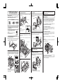
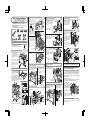
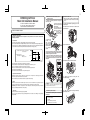
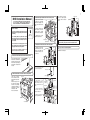
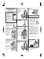
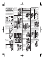
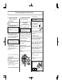
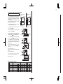
1
Installation Manual for B8300
and Its Peripheral Devices
Finishing device
Finishing device
To install the devices efficiently, follow the procedure below.
Some peripheral devices may have been installed as
standard devies depending on the main unit model.
Part of descriptions and illustrations may be different.
Duplex/bypass device
Finishing device
Main unit
Start of installation
Duplex device
Paper feeding device
Main unit
Paper feeding device
Main unit, paper feeding
device, and power supply
unit.
B83MP / Power Suply Unit... (P. 2)
B83LT / Power Suply Unit..... (P. 3)
B83TT / Power Suply Unit.... (P. 4)
Main unit.................................. (P. 5)
Yes
Duplex/bypass
device installed?
[Electrical setting/adjustment]
Install duplex/pypass device.
1) Installation of driver software, setting,
and operation check
B83D ....................(P. 7)
B83DB ................(P. 8)
Main unit / B83H..............(P. 13)
No
2) Paper guide position adjustment/off center adjustment
B83MP / B83LT / B83TT /
B83D / B83DB.................(P. 14 & 15)
Install finishing device.
Yes
Finishing device
installed?
B83MB/Power Suply Unit... (P. 9)
B83F/Power Suply Unit....... (P. 10 )
B83SS.................................... (P. 11)
B83THP / USP / FHP / FBP.(P. 12)
End
No
1:
Hard
Disk
2
2:
3:
When installing a paper feeding device, an optional power supply unit or a duplex/bypass device, be
sure to reattach the rear cabinet, the AC inlet cover, and the harness cover of the main unit at the end
of installation as needed.
When installing electrical devices, be sure to install them one at a time.
Only off center adjustment is needed for B83D.
2
B83MP Installation Manual
FOR USE WITH COMPATIBLE OKI DIGITAL PRINTERS.
SEE OKI DIGITAL PRINTER SERVICE MANUAL OR
INSTALLATION MANUAL TO DETERMINE SUITABILITY.
<Before installation>
3. Connect the main unit of the printer to the
multi purpose drawer.
<1>Attach the two rear mounting plates using a supplied
screw for each.
When installing a finisher or a mail-bin stacker with
B83MP, a power supply unit is needed.
4. Connect the harness to the main unit of
the printer.
<1> Remove the screw that fixes the harness cover of the
main unit of the printer and then slide the harness cover
up to remove it.
Screw
Screw
Front mounting plates:
2 pcs.
Rear mounting plates:
2 pcs.
Screws (M4x8):
4 pcs.
Turn the main switch located on the
front side of the main unit to the "OFF"
position.
Then, remove the power plug of the
main unit from the outlet.
"OFF"
2. Put the main unit of the printer on the
multi purpose drawer.
<1> Pull out the paper tray of the main unit until it stops
and then remove it by lifting both ends of the tray.
<2> Press the [MENU] key several times to display "SIZE
ADJUSTMENT A" and press the [OK] key.
Screw
Rear mounting plate
1. Turn off the main switch of the main unit
of the printer.
[Caution]
Insert the mounting plate
under the tray frame.
6. Adjust the position of the paper guides of
the paper tray.
<1> To use the setting mode, insert the power plug of the
main unit of the printer to the outlet and turn the main
switch on while pressing the [MENU] key and the [OK] key
of the operation panel of the main unit of the printer.
Rear mounting plate
<Parts included>
* If another peripheral device must be installed,
carry out the following step at the end of the
installation work.
Mounting
plate
Cut out.
Harness cover
Tray frame
<2> Pull out the multi purpose drawer until it stops and
attach the two front mounting plates using a supplied
screw for each.
* Cut out the harness cover as shown in the illustration.
<2> Connect the connector of the relay harness of the
multi purpose drawer to CN10 (blue connector) of the
PCU PWB of the main unit of the printer.
CN10
Then, remove the lock of the paper tray and close the
tray.
Connector
<3> "MAXIMUM SIZE" is displayed.
Pull out the paper tray and extend the paper guides to the
maximum. Then, return the paper tray into the main unit
and press the [OK] key.
<4> "MINIMUM SIZE" is displayed.
Pull out the paper tray again and narrow the paper guides
to the minimum. Then, return the paper tray into the main
unit and press the [OK] key.
<5> Press the [BACK / CLEAR] key to exit the setting
mode.
[Caution]
If the setting above is not carried out, the paper detection
function will not operate.
Front mounting plate
Rear guide
Screw
For installation of a finisher or a mail-bin stacker,
see its installation manual.
<2> Hold the main unit of the printer at the positions
shown in the illustration and put the main unit on the multi
purpose drawer so that the front side and the left side of
the main unit are aligned to those of the multi purpose
drawer.
Paper guide
5. Attach the harness cover.
Screw
Front side
Reattach the harness cover to its original position and fix it
with the removed screw.
Front mounting plate
7. Carry out the off center adjustment.
Screw
Installation is now complete.
<3> Reattach the paper tray of the main unit of the
printer.
Rear side
Harness cover
Wire saddle
[Caution]
For installation of the main unit, it
must be held by two persons and
installed carefully.
Wire saddle
* Fix the harness securely to the wire saddle.
3
4. Connect the main unit to the stand/paper drawer.
B83LT Installation Manual
<1>Attach the two rear
mounting plates using a
supplied screw for each.
FOR USE WITH COMPATIBLE OKI DIGITAL PRINTERS.
SEE OKI DIGITAL PRINTER SERVICE MANUAL OR
INSTALLATION MANUAL TO DETERMINE SUITABILITY.
<Before installation>
• Start installation after checking that the DATA and
COMMUNICATION indicators on the operation panel are
neither lit nor blinking.
• For installation, a power supply unit is needed.
<1> Remove the screw that
fixes the harness cover of the
main unit of the printer and
slide the harness cover up to
remove it.
Rear
mounting plate
Screw
<Parts included>
Rear mounting
plates: 2 pcs.
Front
mounting plate
1. Turn off the main switch of the main unit of the printer.
Screw
<2> Connect the optional
power
supply
harness
connector to CN11 (red
connector) of the PCU PWB of
the main unit of the printer.
<3> Reattach the harness
cover to its original position
and fix it with the removed
screw.
At this time, ensure that the
optional power supply harness
are arranged as shown in the
illustration.
Screw
2. Attach the adjusters and adjust them.
<3> Reattach the paper tray
of the main unit.
Connector
Screw
3
1
5. Remove the rear cabinet of the stand/paper drawer and
remove the AC inlet cover.
2
3. Put the main unit of the printer on the stand/paper drawer.
<1> Pull out the paper tray of
the main unit until it stops and
then remove it by lifting both
ends of the tray.
<1> Remove the four screws that
fix the rear cabinet and then
remove the rear cabinet.
<2> Remove the screw that fixes the
AC inlet cover and then remove the
AC inlet cover.
Right paper guides
Harness cover
Wire saddle
2
Wire saddle
Paper guide
8. Connect the relay harness of the stand/paper drawer to
the power supply unit.
Connect the relay harness of
the stand/paper drawer to the
connector of the power supply
unit.
* If another peripheral device must be installed, carry out
the following step at the end of the installation work.
Connector of the power supply connector
12. Adjust the position of the paper guides of the upper
paper tray of the stand/paper drawer.
<1> To use the setting mode, insert the power plug of the main unit of the
printer to the outlet and turn the main switch on while pressing the [MENU]
key and the [OK] key of the operation panel of the main unit of the printer.
<3> Cut out the AC inlet cover as
shown in the illustration.
<2> Hold the main unit of the
printer at the positions shown
in the illustration and put the main unit on the
stand/paper drawer so that the front side and the
left side of the main unit are aligned to those of
the stand/paper drawer.
Left paper guides
Optional power
supply harness
• Fix the harness securely to
the wire saddle.
2
2
Insert the left paper guides and
right paper guides to the front
and rear guide slots for the
paper size to be used. (See the
illustration below.)
CN11
3
3
Be sure to attach the left
adjuster to prevent overturning.
[Caution] The lower tray
cannot be pulled out unless
the adjuster is lowered to the
specified position.
11. Attach the paper guides to the lower tray.
Remove the four screws for
packing. (See the right
illustration.)
(For the AB system, set the
guides to A4. For the inch
system, set the guides to LT.)
"OFF"
3
Connect the AC cord of the
power supply unit to the inlet
connector of the main unit of
the printer at the location
shown in the illustration.
Cut out.
Then, remove the lock of
the paper tray and close the
tray.
Front mounting plate
10. Connect the AC cord of the power supply unit to the
main unit of the printer.
AC cord
Cut out the harness cover as
shown in the illustration.
Harness cover
<2>Pull out the upper tray
of the stand/paper drawer
until it stops, and attach the
two front mounting plates
using a supplied screw for
each.
Right paper guides: 2 pcs.
Turn the main switch located on the front side of
the printer to the "OFF" position.
Then remove the power plug from the outlet.
<1> Insert the left adjusters to
the stand/paper drawer.
<2> Turn each adjuster to
lower it until it touches the floor.
<3> Attach the four adjuster
covers.
Screw
[Caution]
Insert the rear mounting
plates under the Stand frame.
Screws (M4x8):
4 pcs.
Left adjuster: 1 pc.
Left paper guides: 2 pcs.
Screw
Rear mounting plate
Stand frame
Front mounting
plates: 2 pcs.
Adjuster covers: 4 pcs.
Rear mounting plate
7. Connect the power supply unit harness to the PCU PWB
of the main unit of the printer.
<2> Press the [MENU] key several times to display "SIZE ADJUSTMENT
A" and press the [OK] key.
Cut out.
Rear cabinet
<3> "MAXIMUM SIZE" is displayed.
Pull out the paper tray and extend the paper guides to the maximum.
Then, return the paper tray into the unit and press the [OK] key.
Relay harness of the
stand/paper drawer
Front side
9. Attach the rear cabinet of the stand/paper drawer.
AC inlet cover
6. Attach the power supply unit.
Attach the power supply unit to the brackets and secure it using the three
supplied screws.
<1> Pass the cord of the power supply
unit through the hole of the rear cabinet
and attach the rear cabinet to the
stand/paper drawer.
<2> Attach the AC inlet cover
to the rear cabinet of the
stand/paper drawer and fix it
with the removed screw.
[Caution] If the setting above
is not carried out, the paper
detection function will not
operate.
Bracket
Rear cabinet
Screws
Screws
Power supply unit
Paper guides
13. Carry out the off center adjustment.
AC inlet cover
[Caution]
For installation of the main unit, it must be
held by two persons and installed carefully.
Rear guide
(The rear guide need not be
adjusted.)
Bracket
Rear side
<4> "MINIMUM SIZE" is
displayed. Pull out the paper
tray again and narrow the
paper guides to the minimum.
Then, return the paper tray into
the unit and press the [OK] key.
Screw
Installation is now complete.
4
B83TT Installation Manual
4. Connect the main unit to the stand/paper drawer.
Rear mounting plate
Attach the two rear mounting
plates using a supplied
screw for each.
FOR USE WITH COMPATIBLE OKI DIGITAL PRINTERS.
SEE OKI DIGITAL PRINTER SERVICE MANUAL OR
INSTALLATION MANUAL TO DETERMINE SUITABILITY.
9. Attach the rear cabinet of the stand/paper drawer.
6. Attach the power supply unit.
Attach the power supply unit to the brackets and secure it using the three
supplied screws.
Bracket
<Before installation>
• Start installation after checking that the DATA and
COMMUNICATION indicators on the operation panel are
neither lit nor blinking.
• For installation, a power supply unit (AR-DC1) is needed.
<1> Pass the cord of the power supply
unit through the hole of the rear cabinet
and attach the rear cabinet to the
stand/paper drawer.
<2> Attach the AC inlet cover
to the rear cabinet of the
stand/paper drawer and fix it
with the removed screw.
Bracket
Screw
<Parts included>
Screw
Rear mounting plate
Rear mounting
plates: 2 pcs.
Front mounting
plates: 2 pcs.
Screws (M4x8):
4 pcs.
[Caution]
Insert the rear mounting plates
under the Stand frame.
Mounting plate
Power supply unit
Screws
Left adjuster: 1 pc.
Adjuster covers: 4 pcs.
Stand frame
1. Turn off the main switch of the main unit of the printer.
Turn the main switch located on the front side of the
printer to the "OFF" position.
Then remove the power plug from the outlet.
"OFF"
2. Attach the adjusters and adjust them.
<1> Insert the left adjusters to
the stand/paper drawer.
<2> Turn the five adjusters to
lower them until they touch the
floor.
<3> Attach the four adjuster
covers.
3
3
[Caution] The lower tray
cannot be pulled out unless
the adjuster is lowered to
the specified position.
Screw
1
3. Put the main unit of the printer on the stand/paper drawer.
Cut out.
Front side
AC cord
<2> Connect the optional
power
supply
harness
connector to CN11 (red
connector) of the PCU PWB of
the main unit of the printer.
Screw
Connector
CN11
* If another peripheral device must be installed, carry out
the following step at the end of the installation work.
11. Adjust the position of the paper guides of the
upper paper tray of the stand/paper drawer.
<1> To use the setting mode, insert the power plug of the main unit of the
printer to the outlet and turn the main switch on while pressing the [MENU]
key and the [OK] key of the operation panel of the main unit of the printer.
<3> Reattach the paper tray
of the main unit.
<3> Reattach the harness
cover to its original position and
fix it with the removed screw.
At this time, ensure that the
optional power supply unit
harness is arranged as shown
in the illustration.
5. Remove the rear cabinet of the stand/paper drawer and
remove the AC inlet cover.
<1> Remove the four screws that
fix the rear cabinet and then
remove the rear cabinet.
<2> Remove the screw that fixes
the AC inlet cover and then remove
the AC inlet cover.
<3> Cut out the AC inlet cover as
shown in the illustration.
Rear side
Rear cabinet
[Caution]
For installation of the main unit, it must be
held by two persons and installed carefully.
Connect the AC cord of the
power supply unit to the inlet
connector of the main unit of
the printer at the location
shown in the illustration.
2
<1> Pull out the paper tray of
the main unit until it stops and
then remove it by lifting both
ends of the tray.
<2> Hold the main unit of the
printer at the positions shown
in the illustration and put the main unit on the
stand/paper drawer so that the front side and
the left side of the main unit are aligned to
those of the stand/paper drawer.
Front mounting plate
10. Connect the AC cord of the power supply unit to the
main unit of the printer.
Harness cover
2
3
2
Cut out the harness cover as
shown in the illustration.
Remove the locks of the
middle tray and the lower
tray similarly.
2
• Be sure to attach the left
adjuster
to
prevent
overturning.
Screw
Front
mounting plate
Then, remove the lock of the
paper tray and close the
tray.
4
AC inlet cover
Screw
7. Connect the power supply unit harness to the PCU PWB
of the main unit of the printer.
<1> Remove the screw that
fixes the harness cover of the
main unit of the printer and
slide the harness cover up to
remove it.
<2>Pull out the upper tray of
the stand/paper drawer until
it stops, and attach the two
front mounting plates using
a supplied screw for each.
Rear cabinet
Screws
Screw
Optional power
supply harness
<3> "MAXIMUM SIZE" is displayed.
Pull out the paper tray and extend the paper guides to the maximum.
Then, return the paper tray into the unit and press the [OK] key.
Harness cover
• Fix the harness securely to
the wire saddle.
Wire saddle
Wire saddle
8. Connect the relay harness of the stand/paper drawer
to the power supply unit.
Connect the relay harness of
the stand/paper drawer to the
connector of the power supply
unit.
Connector of the power supply connector
Cut out.
<2> After pressing the [MENU] key several times to display "SIZE
ADJUSTMENT A" in the message display and press the [OK] key.
<4> "MINIMUM SIZE" is
displayed. Pull out the paper
tray again and narrow the
paper guides to the minimum.
Then, return the paper tray into
the unit and press the [OK] key.
(The rear guide need not be
adjusted.)
[Caution]
If the setting above is not
carried out, the paper detection
function will not operate.
Relay harness of the
stand/paper drawer
Paper guides
13. Carry out the off center adjustment.
Installation is now complete.
AC inlet cover
Rear guide
5
2. Remove the main unit from the carton
B8300 Digital Printer
Main Unit Installation Manual
(requires two people)
<1> Remove the cushioning materials from the right and
left of the front side.
<2> Remove the locking
tape from the right and left
sidesof the tray.
Then, remove the top of
the carton and lower the
plastic bag covering the
machine
while
the machine is
still on the carton
base.
FOR USE WITH COMPATIBLE OKI DIGITAL PRINTERS.
SEE OKI DIGITAL PRINTER SERVICE MANUAL OR
INSTALLATION MANUAL TO DETERMINE SUITABILITY.
1. Select an installation location.
• Installation requirements
Selection of installation location is important to the performance of the machine. Consider the
following conditions.
• Environment
(1) Avoid locations subject to direct sunlight as plastic parts may be deformed.
(2) Avoid high temperature and high humidity locations or where temperatures change rapidly such as
near a heater or air conditioner. Rapid changes can cause paper to be become damp and condensation
to form within the machine resulting in misfeeds and deterioration of image quality.
Standard conditions: Conditions most adequate for
use of the machine
Acceptable temperature
and humidity range: 20%Å8̀5%
Max. 60% at 35Åé
85
60
Humidity
20
35
10
30
<3> Remove the
packing
tape
from the paper
tray, pull out the
paper tray until it
stops and remove
it by tilting it
upward.
<1> Remove the remainder of packing tape from the
operation panel.
<2> Raise the lever of the left door to unlock it and
open the left door.
<3> Open the front cover.
Front side
(3) Avoid a dusty location and a location subject to vibration.
If dust enters the machine, deterioration of image quality or a failure may occur.
(4) Do not install the machine in a location that is not stable.
Be sure to install the machine on a level surface to maintain proper functions.
(5) Avoid poorly ventilated areas.
(6) Avoid areas near combustibles or any ammonia present.
<4> Rotate the developer unit lock lever down.
Rear side
• Space around the machine
Install the machine so that the rear side is at least 30 cm form any wall or other object to allow the
machine’ cooling fan and ventilation to be effective.
Allow sufficient space around the machine for operation and servicing.
• Grounding
(1) Be sure that the machine is properly grounded.
(2) Use a proper ground such as the grounding terminal on an outlet or according to local grounding
requirements.
(Be sure to carry out this step after the paper
feeding device has been connected to the main
unit.)
One person must lift by the empty front tray pocket with
the right hand and steady the machine with the left hand
placed at the upper left of the machine.
The other person must lift with the right hand by using
the lifting recess in the rear of the machine and also
steady the machine with the left hand as shown in the
illustration.
Temperature
• Stand
Ensure that the machine is leveled using a level or the like. If the machine is not placed on a level
surface, the toner density control may not function properly, resulting in poor image quality.
[Caution] If the machine is not placed on a level surface, the toner density control may not function
properly, resulting in bad influence on the quality.
4. Install the main unit.
<5> Remove the protective
toner/drum cartridge.
covering
from
the
Caution
Removal of this machine and carrying it must be
always performed by two persons.
3. Check the parts included.
<1> Check that the following items are included with
this machine.
• Drum / Toner cartridge
• Developer cartridge
• CD-ROM
• Safety and Warranty information
• User Guide (may be on CD-ROM)
<6> Shake the toner/drum cartridge horizontally
approximately 5 times.
6
<7> Insert the toner/drum cartridge into the main unit.
<12> Remove the sealing tape from the developer
cartridge in the direction indicated by the arrow.
5. Load paper.
<1> Pull out the paper tray.
Gently pull out the paper tray until it stops.
* If another peripheral device must be installed,
carry out the following step at the end of the
installation work.
<2> Insert the power plug into an outlet.
Caution
If the outlet is also used for lighting fixtures, the lighting
fixtures may flicker.
Use an outlet which is not connected to lighting fixtures.
<8> Remove the drum protective paper in the direction
indicated by the arrow.
<13> Return the developer unit lock to its original
position.
<2> Load paper into the tray.
Do not exceed the maximum height line. (up to 500 sheets
of OKI recommended paper can be loaded)
Caution
While automatic adjustment of the toner density sensor
is being done, do not turn the power to the machine off.
This will cause improper adjustment.
<14> Close the front cover.
Gently close the cover.
<9> Remove the supplied developer cartridge from the
packing case and remove the protective materials A and B.
7. Check the printer operation
A
6. Connecting the machine to a computer.
B
<15> Apply pressure to the fusing roller.
Raise the right and left levers of the fusing unit in the
direction indicated by the arrow.
<10> Shake the developer cartridge horizontally
approximately 5 times and insert it into the machine.
<1> Connect the machine to the computer
• When connecting to a parallel port:
The parallel interface of this machine conforms to
IEEE-STD-1284-1983.
Use a commercially available shielded type parallel interface
cable conforming to the specifications of both the machine
and the computer.
The connector on this machine is a 36-pin Amphenol female
connector.
18
1
36
19
For the specifications of the connector on the computer, see
the operation manual of the computer.
<11> Remove the sealing tape from the toner/drum
cartridge by pulling it in the direction indicated by the
arrow.
<3> Turn on the main switch of the main unit.
Automatic level adjustment of toner density sensor will start
and a message indicating [WARMING UP] will appear on
the operation panel. After the level adjustment is complete,
the ready indicator will light up.
<16> Close the left door.
Parallel interface connector
<17> Turn the lock pin a 1/4 turn and remove it while
pressing down on the pressure plate.
LINE
Remove the lock pin
while holding down on
the paper pressure
plate and insert the
paper tray into the main
unit.
TEL
For installation of printer drivers on the computer refer to the
Operation manual (for printer operation and general
information) supplied with the machine.
After driver installation, execute a test print to ensure normal
printing.
7
B83D Installation Manual
FOR USE WITH COMPATIBLE OKI DIGITAL PRINTERS.
SEE OKI DIGITAL PRINTER SERVICE MANUAL OR
INSTALLATION MANUAL TO DETERMINE SUITABILITY.
Parts included
<Before installation>
• Carry out the installation after checking that the
DATA indicator on the operation panel is neither lit
nor blinking.
M4 Screws
(M4x8) : 1 pcs.
• For installing B83D, an optional desk (multi
purpose drawer, stand/3 x 500 sheet paper drawer
or stand/MPD & 2000 sheet drawer) must have
been installed.
3. Attach the duplex module to the main unit of the printer.
<1> Hang the hooks located at
the upper part of the duplex
module on the openings of the
left door of the main unit of the
printer.
Hook
Hook
<2> Push the lower part of the
duplex module to insert the
positioning bosses securely
into the main unit of the printer.
<3> Tighten the two screws
built in the duplex module.
Relay harness
Duplex module
Positioning boss
* If another peripheral device must be installed, carry out
the following step at the end of the installation work.
4. Connect the harness to the main unit of the printer.
<1> Remove the screw that
fixes the harness cover of the
main unit of the printer and
then slide the harness cover
up to remove it.
• Check that the left adjuster supplied with an
optional stand/drawer has been attached.
Screw
Harness cover
"OFF"
<2> Cut out the harness cover
as shown in the illustration.
Harness cover
2. Remove the left side cover of the main unit of the printer.
Cut out.
Top covers
Left door
<3> Connect the connector of
the relay harness of the
duplex module to the CN12
(white connector) of the PCU
PWB of the main unit of the
printer.
CN12
PCU PWB
Relay harness
connector
Snap bands
<4> Insert the snap bands to
the locations shown in the
illustration and fix them.
<5>Secure the earth harness
using a supplied M4 screw.
Lower cover
Lock release lever
5. Carry out the off center adjustment.
Installation is now complete.
1. Turn off the main switch of the main unit of the printer.
Unlock the lock release
lever of the main unit of the
printer and then pull out the
left door.
Slide the two upper covers
up to remove them. Remove
the lower cover by inserting
a flat-blade screwdriver at
three locations ( ) shown in
the illustration.
Then, close the left door.
Screw
Positioning boss
• Ensure that the front mounting plates and the
rear mounting plates included with the optional
stand/paper drawer are securely attached.
Turn the main switch located on
the front side of the main unit of
the printer to the "OFF" position.
Then, remove the power plug of
the main unit of the printer from
the outlet.
Harness cover
<6> Reattach the harness
cover to its original position
and fix it with the removed
screw.
M4 Screw
Ground harness
8
B83DB Installation Manual
FOR USE WITH COMPATIBLE OKI DIGITAL PRINTERS.
SEE OKI DIGITAL PRINTER SERVICE MANUAL OR
INSTALLATION MANUAL TO DETERMINE SUITABILITY.
Parts included
<Before installation>
• Carry out the installation after checking that
the DATA indicator on the operation panel is
neither lit nor blinking.
• For installing B83DB, an optional desk (multi
purpose drawer, stand/3 x 500 sheet paper
Exit tray
drawer or stand/MPD & 2000 sheet drawer)
must have been installed.
M4 Screws :
• Ensure that the front mounting plates and
1 pcs.
the rear mounting plates included with the
optional stand/paper drawer are securely
attached.
• Check that the left adjuster supplied with an optional stand/drawer
has been attached.
5. Attach the exit tray.
4. Connect the harness to the main unit of the printer.
Screw
<1> Remove the screw that
fixes the harness cover of the
main unit of the printer and
then slide the harness cover
up to remove it.
* If another peripheral device must be installed, carry out
the following step at the end of the installation work.
Harness cover
<2> Process the harness cover
as shown in the illustration.
Harness cover
1. Turn off the main switch of the main unit of the printer.
Turn the main switch located on the front side of the
main unit of the printer to the "OFF" position.
Then, remove the power plug of the main unit of the
printer from the outlet.
Cut out.
"OFF"
2. Remove the left side cover of the main unit of the printer.
Unlock the lock release lever of the
main unit of the printer and then pull
out the left door.
Slide the two upper covers up to
remove them. Remove the lower
cover by inserting a flat-blade
screwdriver at three locations (
)
shown in the illustration.
Then, close the left door.
Top covers
<3> Connect the connector of
the relay harness of the
duplex module to the CN12
(white connector) of the PCU
PWB of the main unit of the
printer.
CN12
PCU PWB
Relay harness
connector
Snap bands
<4> Insert the snap bands to
the locations shown in the
illustration and fix them.
Left door
<5>Secure the earth harness
using the supplied M4 screw.
6. Adjust the position of the paper guides of the bypass tray.
<1> To use the setting mode, insert the power plug of
"ON"
the main unit of the printer to the outlet and turn the
main switch on while pressing the [MENU] key and
the [OK] key of the operation panel of the main unit of
the printer.
<2> After pressing the [MENU] key several times to
display "SIZE ADJUSTMENT A" in the message
display, press the [ ] key to display "SIZE ADJUSTMENT B" and press the
[OK] key.
<3> "MAXIMUM SIZE" is displayed.
Since "MAXIMUM SIZE" is displayed with a number, press the [ ] key or the
[ ] key to change the number so that the number is equal to the value of
[MAX] written on the label( NOTE) and then press the [OK] key.
<4> Since "P1 SIZE" is displayed with a number, press the [ ] key or the [ ]
key to change the number so that the number is equal to the value of [P1]
written on the label( NOTE) and then press the [OK] key.
<5> Since "P2 SIZE" is displayed with a number, press the [ ] key or the [ ]
key to change the number so that the number is equal to the value of [P2]
written on the label( NOTE) and then press the [OK] key.
<6> Since "MINIMUM SIZE" is displayed with a number, press the [ ] key or
the [ ] key to change the number so that the number is equal to the value of
[MIN] written on the label( NOTE) and then press the [OK] key.
[Caution]
If the setting above is not carried out, the paper detection function will not
operate.
Lower cover
Lock release lever
M4 Screw
3. Attach the duplex module to the main unit of the printer.
<1> Hang the hooks located at
the upper part of the duplex
module on the openings of the
left door of the main unit of the
printer.
Hook
Hook
Ground harness
Harness cover
<6> Reattach the harness cover
to its original position and fix it
with the removed screw.
Screw
(Back surface of the bypass tray
extension)
Label
MAX
<2> Push the lower part of the
duplex module to insert the
positioning bosses securely into
the main unit of the printer.
<3> Tighten the two screws built
in the duplex module.
(
NOTE)
Illustration of label sticking position
P1
P2
MIN
7. Carry out the off center adjustment.
Installation is now complete.
Positioning boss
Duplex module
Positioning boss
Relay harness
B83MB Installation Manual
FOR USE WITH COMPATIBLE OKI DIGITAL PRINTERS.
SEE OKI DIGITAL PRINTER SERVICE MANUAL OR
INSTALLATION MANUAL TO DETERMINE SUITABILITY.
<Before installation>
• Start installation after checking that the DATA and
COMMUNICATION indicators on the operation panel are
neither lit nor blinking.
• For installation of B83MB, an optional stand/paper drawer
(stand/MPD & 2000 sheet paper drawer, stand/3 x 500 sheet
paper drawer or multi purpose drawer) must have been
installed.
Also if a multi purpose drawer has been installed, a power
supply unit is needed additionally.
<Parts included>
Mounting plates: 2 pcs.
<3> Hold the grip of the mailbin stacker and place the mailbin stacker on the stand/paper
drawer temporarily.
9
Place.
Grip
Attach the power supply unit to the brackets and secure it using the
supplied three screws.
Bracket
Then, push the lower part to
attach the mail-bin stacker by
sliding it toward the exit tray of
the main unit.
At this time, align the mail-bin
stacker with the exterior line of
the stand/paper drawer.
<4> Open the front cover of the
mail-bin stacker and fix the
stacker with three screws A at
the positions shown in the
illustration.
Then, close the front cover and
close the paper tray of the
stand/paper drawer.
Bracket
Push.
<5> Attach the mounting plates to
the positions shown in the
illustration and fix them with
screws A.
(* Similar work for the multi purpose drawer)
Screw
Optional power supply unit
Screws
(Rear side)
Mounting plate
7. Connect the power supply unit harness to the PCU PWB
of the main unit of the printer.
<1> Remove the screw that
fixes the harness cover of the
main unit of the printer and
slide the harness cover up to
remove it.
1. Turn off the main switch of the main unit of the printer.
Turn the main switch located on the front side of the
main unit to the "OFF" position.
Then, remove the power plug of the main unit from the
outlet.
Rear cabinet
Push.
Grip
(Front side)
Screws A (M4x8): 5 pcs.
Screw
9. Arrange the harness of the mail-bin stacker.
Screw A
Mounting plate
<2> Mount screw B to the
position shown in the
illustration.
Harness cover
10. Attach the rear cabinet of the stand/paper drawer.
Stand frame
Cabinet
Screw A
[Caution] Insert the mounting
plate under the desk frame.
Tray
Screw B
Steps 5 and after are the procedure to be carried out when a
multi purpose drawer has been installed.
If a stand/MPD & 2000 sheet paper drawer or a stand/3 x 500
sheet paper drawer has been installed, carry out steps 8 and
after.
<1> Remove the paper exit
actuator from the main unit
of the printer.
<3> Reattach the harness
cover to its original position
and fix it with the removed
screw.
At this time, ensure that the
power supply unit harness is
arranged as shown in the
illustration.
Connector
CN11
<1> Pass the AC cord of the power
supply unit as shown in the illustration
and fix the rear cabinet of the
stand/paper drawer with the screws.
<2> Attach the AC inlet cover
to the rear cabinet of the
stand/paper drawer and fix it
with the removed screw.
Screw
Optional power
supply harnesses
Rear cabinet
Screw
AC inlet cover
Harness cover
• Fix the harness securely to
the wire saddle.
Wire saddle
5. Process the AC inlet cover attached to the rear cabinet
of the stand/paper drawer.
Wire saddle
Screw
Remove the two screws that
secure the rear cabinet and
remove the rear cabinet.
8. Remove the AC inlet cover and then remove the rear
cabinet of the stand/paper drawer.
Actuator
[Caution]
Do not press on the relay unit
while it is raised.
(Doing so may deform or Relay unit
damage the unit.)
<2> Connect the power supply
unit harness connector to
CN11 (red connector) of the
PCU PWB of the main unit of
the printer.
4. Attach the tray.
3. Attach the mail-bin stacker.
<2> Raise the relay unit at the
side of the mail-bin stacker.
Power supply
unit connector
Mail-bin stacker harness
(* Similar work for the multi purpose drawer)
2. Remove the upper cabinet of the stand/paper drawer.
<1> Pull out the paper tray of
the stand/paper drawer.
Remove the four screws of
the cabinet attached to the
right side of the main unit of
the printer and remove the
cabinet.
Snap band
<1> Pass the harness of the
mail-bin stacker between the
power supply unit and the
frame of the stand/paper
drawer and connect it to the
connector of the power supply
unit.
<2> Fit the snap band
attached to the mail-bin
stacker at the position shown
in the illustration to fix the
harness.
Screws A
"OFF"
<2> Remove the AC cord of
the power supply unit from the
inlet connector of the main unit
of the printer.
Remove the four screws that
fix the rear cabinet and then
remove the rear cabinet.
Ç–
ÇÇ
¡ ©
ÇØ
ïî
Screw B: 1 pc.
Tray: 1 pc.
6. Attach the power supply unit.
Remove the screw that fixes
the AC inlet cover and then
remove the AC inlet cover.
Rear
cabinet
(* Similar work for the multi purpose drawer)
11. Connect the AC cord of the optional power supply unit
to the main unit of the printer.
<1> Connect the AC cord of
the power supply unit to the
inlet connector of the main unit
of the printer at the location
shown in the illustration.
<1> Remove the screw that
fixes the AC inlet cover and
then remove the AC inlet
cover.
AC cord
Screw
Screw
(* Similar work for the multi purpose drawer)
Cut out.
Process the AC inlet cover as
shown in the illustration.
AC inlet cover
Screw
AC inlet cover
(* Similar work for the multi purpose drawer)
Installation is now complete.
10
B83F Installation Manual
FOR USE WITH COMPATIBLE OKI DIGITAL PRINTERS.
SEE OKI DIGITAL PRINTER SERVICE MANUAL OR
INSTALLATION MANUAL TO DETERMINE SUITABILITY.
<Before installation>
• Start installation after checking that the DATA and COMMUNICATION
indicators on the operation panel are neither lit nor blinking.
• For installation of B83F, an optional stand/paper drawer (stand/MPD & 2000
sheet paper drawer, stand/3 x 500 sheet paper drawer or multi purpose drawer)
must have been installed.
Also if a multi purpose drawer has been installed, a power supply unit is
needed additionally.
<Parts included>
Screws A (M4x8): 5 pcs.
Stapling position labels:
2 sheets
Screw B: 1 pc.
Tray 1: 1 pc.
<3> Hold the grip of the finisher
and place the finisher on the
stand/paper drawer temporarily.
Grip
Place.
Then, push the lower part to
attach the finisher by sliding it
toward the exit tray of the main
unit.
6. Process the AC inlet cover attached to the rear cabinet
of the stand/paper drawer.
At this time, align the finisher with
the exterior line of the
stand/paper drawer.
Push.
Grip
<4> Open the front cover of the
finisher and fix the finisher with
three screws A at the positions
shown in the illustration.
Then, close the front cover and
close the paper tray of the
stand/paper drawer.
Steps 6 and after are the procedure to be carried out when a multi
purpose drawer has been installed.
If a stand/MPD & 2000 sheet paper drawer or a stand/3 x 500 sheet
paper drawer has been installed, carry out steps 9 and after.
Push.
<5> Attach the mounting plates to the
positions shown in the illustration and
fix them with screws A.
Mounting plates: 2 pcs.
(Rear side)
Remove the screw that fixes the
AC inlet cover and then remove
the AC inlet cover.
Rear
cabinet
Screw
Rear cabinet
AC inlet cover
Screw
Process the AC inlet cover as
shown in the illustration.
Mounting plates
Screw
AC
cover
AC inlet
inlet cover
Staple cartridge: 1 pc.
Attach the power supply unit to the brackets and secure it using the supplied
three screws.
Bracket
Screws A
"OFF"
Bracket
Mounting plate
Stand frame
Cabinet
Screws A
Finisher harness
(* Similar work for the multi purpose drawer)
[Caution] Insert the mounting plate
under the desk frame.
11. Attach the rear cabinet of the stand/paper drawer.
Screws
4. Insert the staple cartridge.
8. Connect the power supply unit harness to the PCU PWB
of the main unit of the printer.
<1> Pull out the staple unit.
<2> Remove the sealing tape from the staple cartridge.
<3> Insert the staple cartridge.
<4> Slide the release lever to the left and return the staple unit.
<1> Remove the screw that fixes
the harness cover of the main
unit of the printer and slide the
harness cover up to remove it.
Screw B
Power supply unit
connector
Screws
Optional power supply unit
<2> Mount screw B to the
position shown in the
illustration.
Snap band
<1> Pass the harness of the
finisher between the power
supply unit and the frame of the
stand/paper drawer and connect
it to the connector of the power
supply unit.
<2> Fit the snap band attached to
the finisher at the position shown
in the illustration to fix the
harness.
2. Remove the upper cabinet of the stand/paper drawer.
<1> Pull out the tray of the
stand/paper drawer.
Remove the four screws
attached to the right on the top of
the stand/paper drawer and
remove the cabinet.
(* Similar work for the multi purpose drawer)
10. Arrange the harness of the finisher.
7. Attach the power supply unit.
Screws A
<2> Remove the AC cord of the power
supply unit from the inlet connector of the
main unit of the printer.
Remove the four screws that fix the rear
cabinet and then remove the rear cabinet.
Cut out.
1. Turn off the main switch of the main unit of the printer.
Turn the main switch located on the front side of the
main unit to the "OFF" position.
Then, remove the power plug of the main unit from
the outlet.
<1> Remove the screw that
fixes the AC inlet cover and
then remove the AC inlet
cover.
Screw
Remove the two screws that
secure the rear cabinet and
remove the rear cabinet.
(Front side)
Tray 2: 1 pc.
10. Remove the AC inlet cover and then remove the rear
cabinet of the stand/paper drawer.
<1> Pass the AC cord of the power supply
unit as shown in the illustration and fix the
rear cabinet of the stand/paper drawer with
the screws.
<2> Attach the AC inlet cover to
the rear cabinet of the
stand/paper drawer and fix it
with the removed screw.
Screw
Process the harness cover as
shown in the illustration.
Rear cabinet
Harness cover
<2> Connect the power supply
unit harness connector to CN11
(red connector) of the PCU PWB
of the main unit of the printer.
3. Attach the finisher.
Connector
CN11
5. Attach the trays .
Attach tray 1 and tray 2 to
the positions shown in the
illustration.
<2> Raise the relay unit at the
side of the finisher.
[Caution]
Do not press on the relay unit
while it is raised.
(Doing so may deform or damage
the unit.)
Tray 1
<3> Reattach the harness cover
to its original position and fix it
with the removed screw.
At this time, ensure that the
power supply unit harness is
arranged as shown in the
illustration.
Screw
<1> Connect the AC cord of
the power supply unit to the
inlet connector of the main
unit of the printer at the
location shown in the
illustration.
Optional power
supply harnesses
AC cord
Relay unit
Tray 2
Harness cover
• Fix the harness securely to the
wire saddle.
Wire saddle
Wiresaddle
saddle
Wire
AC inlet cover
12. Connect the AC cord of the optional power supply unit
to the main unit of the printer.
<1> Remove the paper exit
actuator from the main unit of
the printer.
Actuator
Screw
(* Similar work for the multi purpose drawer)
Installation is now complete.
11
B83SS Installation Manual
FOR USE WITH COMPATIBLE OKI DIGITAL PRINTERS.
SEE OKI DIGITAL PRINTER SERVICE MANUAL OR
INSTALLATION MANUAL TO DETERMINE SUITABILITY.
<Before installation>
For installation of B83SS, an optional stand/paper drawer
(stand/MPD & 2000 sheet drawer or stand/3 x 500 sheet paper
drawer) and a duplex module B83D must have been installed. Also a
power supply unit is needed.
<Parts included>
4. Attach the grounding plate to the stand/paper drawer.
Remove the two screws
that fix the exterior of
the stand/paper drawer.
Then, attach the front
mounting plate and the
rear mounting plate to
the stand/paper drawer
using screws C (two for
each).
Screws C
Screws C
5. Install the staple unit to the finisher.
<2> Open the front cover of the
finisher and insert the staple unit.
<1> Remove the two pieces of
packing tape from the locations
shown in the illustration.
Stapling position labels:
2 sheets
Front cover:
1 pc.
Screws A
(M4x6):
6 pcs.
Front grounding
plate: 1 pc.
Rear grounding
plate: 1 pc.
Screws B
(M4x10):
2 pcs.
Connecting plate:
1 pc.
Screws D
(M4x10 with rosette):
1 pcs.
Screws C
(M4x18):
7 pcs.
1. Turn off the main switch of the main unit of the printer.
Turn the main switch located
on the front side of the main
unit to the "OFF" position.
Then remove the power plug
of the main unit from the outlet.
"OFF"
2. Attach the lock securing plate to the duplex module.
<1> Remove the screw from the
right side of the duplex module.
<2> Attach the lock securing
plate to the duplex module
using the screws C and D (one
for each).
Packing tape
Screws C
Move the finisher toward the printer
and check to see if the guide pin of
the locking plate is inserted
smoothly to the connecting hole of
the finisher.
If it is not inserted smoothly, use
the following procedure to adjust
the height.
Sub cover
Guide pin
Cap
<2> Remove the cap using
a flat-blade screwdriver or
the like and adjust the
height adjusting pin so that
the guide pin is positioned
to the center of the
connecting hole of the
finisher.
Height
adjusting
screw
Screw at
adjusting
portion
Screws B
Screw
Screw at adjusting portion
Rear side
AC inlet cover
Screw
11. Connect the finisher connector.
Screws A
Plate R
Cut out the two mounting holes
of the stand/paper drawer using
a screwdriver or the like and
remove burrs using a flat-blade
screwdriver or the like.
7. Connect the finisher to the stand/paper drawer.
<1> Remove the cover from
the finisher stand.
Cover
<2> Attach the connecting
plate to the finisher using two
screws A.
Mounting
holes
Finisher stand
<3> Reattach the cover to its
original position.
Pawl
Left adjuster
Mounting
holes
<1> Connect the finisher
connector to the stand/paper
drawer.
<2> Tighten the screw of the
connector.
<1>Push the finisher into the
main unit.
3. Work the stand/paper drawer.
Open the pawl of the left
adjuster to both sides to unlock
it that is located at the lower left
of the stand/paper drawer and
remove the left adjuster.
Remove the screw that fixes
the AC inlet cover and then
remove the AC inlet cover.
Exterior lines
2. If the guide pin of the locking plate matches to the connecting hole
of the finisher:
Screws A
9. Paste the stapling position labels.
Paste the labels to the positions
shown in the illustration.
10. Remove the AC inlet cover from the rear cabinet of the
stand/paper drawer.
Height adjusting
screw
Exterior lines
Screw C
Lock securing plate
Screw at adjusting portion
Cap
Front cover
Screw D
Front side
Screw at adjusting portion
Front side
<5> If the guide pin can be
inserted smoothly, tighten
the screws at the front and
rear adjusting portions and
mount the caps.
<2> Attach the front cover
to the finisher, and secure
the upper part using two
screws B and the lower
part using two screws A.
Screw
Screw
<4> Adjust the height
adjusting pin so that the
exterior lines are aligned
as shown in the illustration.
Front cover
Height
adjusting screw
Sub cover
Rear side
Connecting
hole
<1> Loosen the screw at
the rear adjusting portion.
<3> Loosen the screw at
the front adjusting portion.
6. Attach the cover to the finisher.
<1> Attach the plate R to
the position shown in the
illustration and secure it
using two screws A.
Stand/paper drawer
Connecting plate
1. If the guide pin of the lock securing plate is not aligned with the
connecting hole of the finisher:
Packing tape
Cap
Cap
8. Check and adjust the height of the finisher.
Front grounding plate
Staple unit: 1 pc.
<4>If the gap becomes uniform, tighten the screws at the adjusting
portions and reattach the caps and sub covers.
<5>
Attach
the
finisher
connecting
plate
to
the
stand/paper drawer using two
screws C.
Rear grounding plate
Lock securing plate:
1 pc.
Plate R: 1 pc.
Exterior
fixing screw
Exterior
fixing screw
<4> Cut out the two mounting
holes for the connecting plate at
the lower part of the stand/paper
drawer in a similar way to step 3.
Screws A
Connecting plate
<2>If the gap between the
main unit of the printer and
the finisher is not uniform at
the top and the bottom,
remove the caps from the
front side and the rear side of
the finisher stand using a flatblade screwdriver or the like
and remove the screw of the
sub covers on the front side
and the rear side to remove
the sub covers.
<3>Then, loosen the four
screws at the adjusting
portions indicated in the
illustration and turn the height
adjusting screws on the front
side and the rear side so that
the gap becomes uniform.
Screw
Connector
Gap
12. Turn on the main switch of the main unit.
Insert the power plug of the
main unit to the outlet.
Turn on the main switch of the
main unit.
Finisher stand
Gap
Installation is now complete.
"ON"
12
B83THP / USP / FHP / FBP
Installation Manual
FOR USE WITH COMPATIBLE OKI DIGITAL PRINTERS.
SEE OKI DIGITAL PRINTER SERVICE MANUAL OR
INSTALLATION MANUAL TO DETERMINE SUITABILITY.
<Before installation>
For installation of B83THP / USP / FHP / FBP, a saddle stitch
finisher B83SS must have been installed.
Parts included
Harness B (orange): 1 pc.
Harness A (purple): 1 pc.
Screw
(M4 x 6 with rosette)
: 1 pc.
Dust box label:
1 sheet
Hole punch position label:
2 sheets
<2> Remove the four front
cabinet securing screws, pull
out the staple unit until it stops,
then remove the pawl of the
front cabinet in the direction
indicated by the arrow and
remove the front cabinet.
6. Connect the harness of the punch module to the PWB
of the finisher.
Pawl
Remove the clamps that fix
the harness, handle the wiring
of harness A (purple) and
harness B (orange), and fix
them with the clamps.
Staple unit
<3> Remove the three screws
that fix the rear cabinet and
remove the rear cabinet.
At this time, remove the relay
harness through the opening
of the rear cabinet.
8. Reattach the front cover to the right front of the finisher.
Screws
Harness A (purple)
<4> Remove the three rear
cabinet securing screws,
remove the pawl in the
direction indicated by the
arrow, and remove the rear
cabinet.
At this time, remove the relay
harness through the opening
of the rear cabinet.
Clamps
Rear
cabinet
Screw
Screws B
Harness B (orange)
Clamps
Opening for
relay harness
Harness A (purple)
Screws A
4. Remove the top cover.
"OFF"
Screws
Connector
<1> Remove the four top cover
securing screws and remove the top
cover.
Screws
Top cover
<2> Remove the four pawls
from the top cover and
separate the cover into the
upper and lower portions.
Reuse the upper portion.
Pawl
Top cover
Pawl
Front cover
Screws B
7. Reattach the covers that have been removed.
<1> Hang the two pawls of
the top cover and secure
them using the two screws.
<2> Pass the relay harness to
the rear cabinet and secure
the rear cabinet using the
three screws.
<3> Remove the lock release
lever that has been attached
to the front cabinet.
Reattach the front cabinet to
its original position, push in
the staple unit, and attach it
using the two screws.
Insert the protrusion (B) of the
lock release lever that has
been removed before to the
hole (C) of the latch arm.
Screw
Screw
Top cover
10. Connect the connector to the stand/paper drawer and
connect the AC cord of the power supply unit to the
main unit of the printer.
Pawl
After attaching it, move the
lever to check that it moves
smoothly.
5. Attach the punch module.
<1> Insert the two bosses of the punch unit into the boss holes of the
finisher and fix the punch module using three screws.
(Note)
For the screws, use a supplied screw and the two screws that have been
removed in step 4.
Boss hole
Boss hole
3. Remove the front cabinet and the rear cabinet from
the finisher.
Boss
Screw
If the lever does not move
smoothly, remove the lock
release lever by releasing the
pawl at the lower part of the
lock release lever using a flatblade screwdriver or the like
and then insert it again.
Relay harness
Connector
Boss
Pawl (D)
Installation is now complete.
Staple unit
(C)
Punch module
Screw
Lock release lever (A)
Screws
Front cabinet
Screw (with rosette) (supplied with this module)
AC cord
Screws
Screws
Screw
Jam handling dial
Connect the connector of the
relay harness of the finisher to
the stand/paper drawer and
tighten the screws of the
connector.
Opening for
relay harness
Latch arm
<1> Open the front
door of the finisher and
remove
the
jam
handling dial.
9. Paste the dust box label to the top cover.
Paste the supplied dust box
label to the location indicated
in the illustration.
Rear cabinet
Screws A
Front cover
Pawl
Relay harness
2. Remove the front cover from the right front of the finisher.
Remove the screws A and B
(two for each) that secure the
finisher front cover and
remove the front cover.
Attach the front cover using
the screws A and B (two for
each).
Front cabinet
Screws
Screw
Loosen the screw and remove
the connector of the finisher.
Jam handling dial
Harness B (orange)
1. Turn off the main switch of the main unit of the printer.
Turn the main switch located
on the front side of the main
unit to the "OFF" position.
Then remove the power plug
of the main unit from the outlet.
<4> Reattach the jam
handling dial and close the
front cover.
Projection (B)
13
B83HD Installation Manual
FOR USE WITH COMPATIBLE OKI DIGITAL PRINTERS.
SEE OKI DIGITAL PRINTER SERVICE MANUAL OR
INSTALLATION MANUAL TO DETERMINE SUITABILITY.
<Before installation>
• Start installation after checking that the DATA and
COMMUNICATION indicators on the operation panel are
neither lit nor blinking.
Remove the five screws that
fix the control PWB unit to
the main unit of the printer.
Then, hold the two grips and
pull out the printer control
PWB unit to remove it from
Screws
the main unit.
Attach the control PWB unit to
the main unit of the printer and
fix it using five screws.
Grip
(Example) MFP control PWB
Parts included
5. Attach the control PWB.
3. Remove the control PWB unit.
Screws
Grip
Screws
(Example) MFP control PWB
4. Mount the HDD expansion PWB to the control PWB.
• The procedure (shape of PWB) varies with the printer control PWB and
the MFP control PWB.
PWB fixing screws: 3 pcs.
Grounding plate: 1 pcs.
screws: 1 pcs.
1. Turn off the main switch of the main unit of the printer.
Turn the main switch
located on the front
side of the main unit to
the "OFF" position.
Then
remove
the
power plug from the
outlet.
"OFF"
"OFF"
2. Remove the cables connected to the control PWB unit.
Remove all the cables connected to the control PWB unit of the main unit of the
printer.
• In case of printer control PWB
• In case of MFP control PWB
• In case of printer control PWB ..................................................................................
<1> Remove the screw at the position shown in the
illustration among the screws that secure the hard
disk to the HDD expansion PWB.
<2> Attach the supplied grounding plate to the HDD
PWB as shown in the illustration
and secure it using the screw that
has been removed in step <1>.
<3> Remove the three screws
shown in the illustration among
the screws that fix the printer
control PWB.
<4> Mount supplied three PWB
fixing screws to the positions from
HDD expansion PWB
which three screws have been
removed.
<5> Insert the HDD expansion
PWB to the connector of the
printer control PWB.
<6> Fix the HDD expansion PWB
to the PWB fixing screws using
the three screws that have been
removed in step 1.
<7> Secure the grounding plate that
has been attached to the HDD
expansion
PWB to the controller mounting
plate using the supplied screw.
• In case of MFP control PWB ......................................................................................
<1> Remove the three screws
HDD expansion PWB
shown in the illustration among
the screws that fix the MFP
control PWB.
<2> Mount supplied three PWB
fixing screws to the positions from
which three screws have been
removed.
<3> Insert the HDD expansion
PWB to the connector of the MFP
control PWB.
<4> Fix the HDD expansion PWB
to the PWB fixing screws using
the three screws that have been
removed in step 1.
6. Connect the cables to the control PWB.
Connect all the cables that have been removed in step 2 to the original positions
of the printer control PWB unit.
• In case of printer control PWB
• In case of MFP control PWB
* If another peripheral device must be installed, carry out
the following step at the end of the installation work.
7. Turn on the main switch of the main unit of the printer.
Insert the power plug of the
main unit of the printer to the
outlet.
Then, turn the main switch
located on the front side of the
main unit to the "ON" position.
"ON"
"ON"
8. Check the operation.
• For setting change of the printer drivers on the computer, see the supplied
operation manual.
Then, execute printing from the computer using the print hold function to check
for proper printing.
14
Electrical Setting/ Adjustment/ Operation Check
[1] Installation of driver software,
setting, and operation check
[2] Paper guide position adjustment
and off center adjustment
• Applied model: Main unit
Carry out installation of driver software and check
of printing
<1> Insert the power plug into an outlet.
Caution
If the outlet is also used for lighting fixtures, the lighting
fixtures may flicker.
Use an outlet which is not connected to lighting
fixtures.
<2> Turn on the main switch of the main unit.
Automatic level adjustment of toner density sensor will
start and a message indicating [WARMING UP] will
appear on the operation panel. After the level adjustment
is complete, the ready indicator will light up.
Caution
While automatic adjustment of the toner density
sensor is being done, do not turn the power to the
machine off. This will cause improper adjustment.
<3>Check the printer operation
For installation of printer drivers on the computer refer to
the Operation manual (for printer operation and general
information) supplied with the machine.
After driver installation, execute a test print to ensure
normal printing.
For Printer Models
[Applied models]
B83MP/ B83LT / B83TT/ B83D / B83DB
• Applied models: B83MP/ B83LT / B83TT
Adjust the position of the paper guides of the
paper tray of B83MP or the upper paper tray of
stand/paper drawer B84LT / B83TT.
<1> To use the setting mode, insert the power plug of the
main unit of the printer to the outlet and turn the main
switch on while pressing the [MENU] key and the [OK]
key of the operation panel of the main unit of the printer.
<2> Press the [MENU] key several times to display "SIZE
ADJUSTMENT A" and press the [OK] key.
<3> "MAXIMUM SIZE" is displayed.
Pull out the paper tray and extend the paper guides to the
maximum. Then, return the paper tray into the main unit
and press the [OK] key.
<4> "MINIMUM SIZE" is displayed.
Pull out the paper tray again and narrow the paper guides
to the minimum. Then, return the paper tray into the main
unit and press the [OK] key.
[Caution]
If the setting above is not carried out, the paper detection
function will not operate.
Rear guide
• Applied model: B83HD
Adjust the position of the paper guides
of the bypass tray.
<1> To use the setting mode,
insert the power plug of the main
unit of the printer to the outlet
and turn the main switch on
while pressing the [MENU] key
and the [OK] key of the operation
panel of the main unit of the
printer.
"ON"
<2> After pressing the [MENU] key several times to
display "SIZE ADJUSTMENT A" in the message display,
press the [ ] key to display "SIZE ADJUSTMENT B" and
press the [OK] key.
<3> "MAXIMUM SIZE" is displayed.
Since "MAXIMUM SIZE" is displayed with a number,
press the [ ] key or the [ ] key to change the number so
that the number is equal to the value of [MAX] written on
the label ( NOTE) and then press the [OK] key.
<4> Since "P1 SIZE" is displayed with a number, press
the [ ] key or the [ ] key to change the number so that
the number is equal to the value of [P1] written on the
label ( NOTE) and then press the [OK] key.
<5> Since "P2 SIZE" is displayed with a number, press
the [ ] key or the [ ] key to change the number so that
the number is equal to the value of [P2] written on the
label ( NOTE) and then press the [OK] key.
<6> Since "MINIMUM SIZE" is displayed with a number,
press the [ ] key or the [ ] key to change the number so
that the number is equal to the value of [MIN] written on
the label
( NOTE) and then press the [OK] key.
[Caution]
If the setting above is not carried out, the paper detection
function will not operate.
Carry out installation of driver software and
check of printing
For setting change of the printer drivers on the computer,
see the supplied operation manual.
Then, execute printing from the computer using the print
hold function to check for proper printing.
• Applied model: B83DB
Paper guides
( NOTE)
Illustration of label sticking position
(Back surface of the bypass tray
extension)
Label
MAX
P1
P2
MIN
Then, carry out the off center adjustment.
15
•
Applied models: B83MP / B83LT / B83TT / B83D / B83DB
(Fig. 1)
Carry out the off center adjustment.
(Fig. 2)
[Rear side of the main unit]
<1> To select the setting mode, insert the power plug of
the main unit of the printer into an outlet and turn on the
main switch while pressing the [MENU] key and the [OK]
key simultaneously.
When carrying out the off center adjustment after paper
guide position adjustment, this operation is not needed.
(For B83D, this operation is needed.)
[Rear side of the main unit]
Top end of paper
Top end of paper
Center of paper
Center of paper
Example
of image
Example
of image
<2> Press the [MENU] key repeatedly until "TEST PRINT
00" is displayed, and press the [OK] key.
Center line of image
(first print image)
In this case, increase the value.
<3> Use the [MENU] key to select "MULTI SETTING" and
enter "1" using the [ / ] key.
<4> Use the [MENU] key to select "PRINT PATTERN"
and enter "1" using the [ / ] key.
Center line of image
(first print image)
In this case, decrease the value.
(ADU)
Main unit
<5> Use the [MENU] key to select "CASSETTE" and
select the tray for which the off center adjustment is to be
carried out using the [ / ] key. (See the table below.)
TRAY 1 (T1)
BPT (MFT)
TRAY 2 (T2)
<6> Use the [MENU] key to select "DUPLEX" and select
"USE" or "NO" using the [ / ] key. (See the table below.)
(ADU)
<7> Use the [MENU] key to select "** OFF CENTER ADJ"
corresponding to the option in the table below, press the
[OK] key, and check that the printed line is positioned at
the center of paper.
Main unit
TRAY 1 (T1)
BPT (MFT)
<8> If the off center is displaced, use the [ / ] key to
adjust the value so that the line is positioned at the center.
(Fig. 1 and 2)
TRAY 2 (T2)
LCC (T3)
Default: 50 (setting range: 0 to 99)
Increase of the value shifts the overall image toward the
rear side.
Value 1 corresponds to 0.1 mm.
LCC (T4)
(ADU)
Main unit
<9> Turn off the main switch of the main unit of the printer
and then turn on the switch again after several seconds.
TRAY 1 (T1)
BPT (MFT)
TRAY 2 (T2)
The setting is now complete.
DESK 1 (T3)
DESK 2 (T4)
■ Setting example for each model
[MENU] key
B83MP
B83LT
B83TT
B83DB
B83D
1
TEST PRINT 00
•
•
•
•
•
•
•
•
•
•
2
MULTI SETTING
1
1
1
1
1
1
1
1
1
1
1
1
1
1
1
1
1
1
TRAY 2
LCC
LCC
LCC
DUPLEX
NO
NO
NO
OFF CENTER ADJ
T2
T2
T3( 1)
3
PRINT PATTERN
4
CASSETTE
5
6
*
( 1) Load paper only in the left tray.
*
*
NO
*
T4( 2)
TRAY 2 DESK 1 DESK 2 TRAY 1
1
1
BPT
TRAY 1
NO
NO
NO
USE
NO
USE
T2
T3
T4
ADU
MFT
ADU
( 2) Load paper only in the right tray.