1
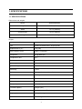
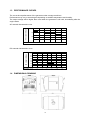
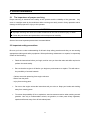
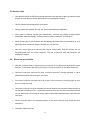
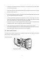
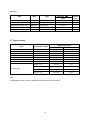
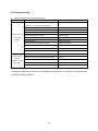
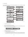
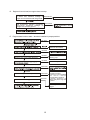
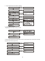
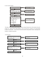
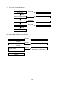
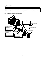
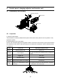
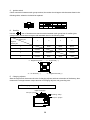
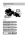
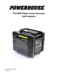
KIPOR
KIPOR POWER
GENERATOR SHOP MANUAL
SINEMASTER
DIGITAL GENERATOR
KGE3000Ti
Preface
This manual covers the construction, function and servicing procedure of the KIPOR KGE3500Ti and
Coast Distribution model KGE3000Ti generators. This manual is principally concerned with the
generator specifications, function, troubleshooting and repair. There is a separate manual to cover
engine overhaul which includes the starting systems.
Careful observance of the instructions contained in this manual will result in safe and quality service
work.
All information, illustrations, directions and specifications included in this publication are based on
the latest product information available at the time of approval for printing.
KIPOR POWER CO., LTD, reserves the right to make changes without incurring any obligation
whatever. No part of this publication may be reproduced without written permission.
Table of Contents
1. Specifications .....................................................................................................................3
1.1 Specifications.................................................................................................................3
1.2 Characteristics .............................................................................................................4
1.3 Performance curves .....................................................................................................7
2. Service information ............................................................................................................8
2.1 The importance of proper service ................................................................................8
2.2 Important safety precautions .........................................................................................8
2.3 Service rules ..................................................................................................................9
2.4 Electrical Precautions ....................................................................................................9
2.5 Serial number location...................................................................................................10
2.6 Maintenance standards .................................................................................................11
2.7 Torque values ................................................................................................................12
2.8 Troubleshooting ...........................................................................................................13
3. Maintenance ........................................................................................................................24
3.1 Regular inspection schedule .........................................................................................24
3.2 Engine oil .......................................................................................................................25
3.3 Inspection of engine alert switch ...................................................................................26
3.4 Air filter maintenance.....................................................................................................27
3.5 Sparkplug service ........................................................................................................28
3.6 Adjusting of valve clearance..........................................................................................30
3.7 Fuel filter and fuel switch maintenance .......................................................................31
4. Air filter and Muffler .............................................................................................................32
4.1 Air filter...........................................................................................................................32
4.2 Muffler ............................................................................................................................33
5. Carburetor............................................................................................................................34
5.1 Carburetor removal and installation ..............................................................................34
5.2 Stepping Motor disassembly and reassembly ..............................................................35
5.3 Carburetor disassembly and reassembly......................................................................36
6. Control panel, charging adjustor and inverter unit..............................................................38
6.1 Assembly and disassembly ...........................................................................................38
6.2 Inspection.......................................................................................................................38
7. Housing group , fuel tank assembly and disassembly .......................................................41
8. Generator, ignition coil and trigger ....................................................................................42
8.1 Generator.......................................................................................................................42
8.2 ignition coil and trigger...................................................................................................43
1. SPECIFICATIONS
1.1 SPECIFICATIONS
Dimensions and weights
Model
KGE3000/3500Ti
Length
27 in (686mm)
Width
16.7 in (425mm)
Overall height
19.9 in (495mm)
Net weight
132 lbs, 60 kg
Engine
Model
KG205
Type
4-stroke,overhead valve, single cylinder
Displacement in (cc)
12.0 (196)
Bore x stroke in.(mm)
2.68 x 2.13 (68×54)
Horsepower
4.0 @ 3600 rpm
Compression ratio
8.5:1
Cooling system
Forced air
Ignition system
T.C.I
Ignition timing
25 B.T.D.C
Spark plug
F7RTC
Carburetor
Float type, horizontal butterfly valve
Air cleaner
Semi-dry
Governor
Electronic control
Lubrication system
Forced splash
Oil capacity
.63 qt (0.6L)
Fuel tank capacity
3.43 gal (13L)
Starting system
Recoil starter and Electrical starter
Stopping system
Primary circuit ground
Fuel
Unleaded gasoline 87 octane
1
Alternator
Model
KD 35
Generator type
Multi pole rotation type
Generator structure
Self-ventilation drip-proof type
Excitation
Self-excitation (Magnet type)
Voltage regulation system
PWM(Plush width modulation)
Phase
Three phase
Rotating direction
Clockwise (Viewed from the generator)
Frequency regulation
AC-DC-AC conversion (Inverter type)
1.2 CHARACTERISTICS
Model
KGE3000Ti/KGE3500Ti
Maximum output watts/amps
3000/25 Amps
Rated output watts/amps
2800/23 Amps
Rated frequency
60 HZ
Rated voltage AC
120V
DC Voltage/current
12V/8.3 Amps
Power factor
1.0cosφ
Voltage variation rate-
Momentary
10%max.
Average
1.5%max.
Average time
3 sec. max.
Voltage stability
±1%
Frequency variation rate Momentary
1%max.
Average time
1%max.
1 sec. max.
Frequency stability
±0.1%
Insulation resistance
10MΩ min.
AC circuit protector
26A(120V)
DC circuit protector
14A
Operating hours at rated load
7 Hours
Noise level dBA @ 23’ (7M)
62~67
2
1.3
PERFORMANCE CURVES
AC output voltage
The curves show performance of the generator under average conditions.
Performance may vary to some degree depending on ambient temperature and humidity.
The output voltage will be higher than usual when the generator is still cold, immediately after the
engine starts.
AC external characteristic curve
120
110
Current ( A) 0
10
5
15
20
25
DC output voltage
DC external characteristic curve
26
24
22
20
18
16
14
12
Current(A)
0
1.4
2
4
6
DIMENSIONAL DRAWING
3
8
10
12
1.5
WIRING DIAGRAM
DC socket
Blue
Blue
Red
Charging winding
Blue
Blue
Rectifier Bridge
Green
Red
Red
Green
Black
Black
Black
Black
White
Brown
Black
Main winding
Inverter unit
stepping motor
Yellow
Orange
Sub winding
Blue
White
Pink
Green
OFF
Low oil switch
M
Triggering winding
DC contactor
Black
Starting motor
Yellow
White
2
3
ON
START
4
Black
White
Brown Running Indication
Gray
Red
Green
Olivine Overload indication
Yellow
Orange
Blue
Low oil indication
Red
Green
Olivine
Yellow
Orange
Blue
flameout
Ignition winding
Lock of
electrical
door
Charging
adjustor
24V winding
Purple
Blue
High voltage
unit
White
Purple
Single phase socket
Olivine
Gray
spark plug
Throttle switch
Black
Red
Olivine
4
1
5
2. Service information
2.1
The importance of proper servicing
Proper servicing is essential to the safety of the operator and the reliability of the generator. Any
error or oversight made by the technician while servicing can easily result in faulty operation and/or
damage to the equipment or injury to the operator.
WARNING
■ Improper servicing can cause an unsafe condition that can lead to serious injury or death.
■ Follow the procedures and precautions in this shop manual carefully.
Some of the most important precautions are stated below.
2.2 Important safety precautions
Be sure you have a clear understanding of all basic shop safety practices and that you are wearing
appropriate clothing and safety equipment. When performing maintenance or repairs, be especially
careful of the following:
·
Read the instructions before you begin, and be sure you have the tools and skills required to
perform the tasks safely.
·
Be sure that the engine is off before you begin any maintenance or repairs. This will reduce
the possibility of several hazards:
- Carbon monoxide poisoning from engine exhaust.
- Burns from hot parts.
- Injury from moving parts.
·
Do not run the engine unless the instructions tell you to do so. Keep your hands and clothing
away from rotating parts.
·
To reduce the possibility of fire or explosion, exercise extreme caution when working around
gasoline. Use only a nonflammable solvent, not gasoline, to clean parts. Keep cigarettes,
sparks and flames away from all fuel-related parts.
5
2.3 Service rules
·
Use genuine KIPOR or KIPOR-recommended parts and lubricants or their equivalents. Parts
that do not meet Kipor’s design specifications may damage the engine.
·
Use the special tools designed for the product.
·
Always install new gaskets, O-rings, etc. when reassembling components.
·
Clean parts in cleaning solvent upon disassembly. Lubricate any sliding surfaces before
reassembly. After reassembly, check all parts for proper installation and operation.
·
Many screws used in this machine are self-tapping. Be aware that cross-threading or over
tightening these screws will strip the threads and ruin the hole.
·
Use only metric tools when servicing this engine. Metric bolts, nuts and screws are not
interchangeable with non metric fasteners. The use of incorrect tools and fasteners will
damage the engine.
2.4
Electrical precautions
·
Hold the connector body to disconnect the connector. Do not disconnect by pulling the wire
harness. To disconnect the locking connector, be sure to unlock first, and then disconnect.
·
Check the connector terminals for bend, excessive extrusion, missing terminals, or other
abnormalities before connecting the connector.
·
To connect, insert the connector as far as it goes. If the connector is a locking type, be sure
that it is locked securely.
·
Check the connector cover for breakage and check whether the connector female terminal is
not opened excessively. Then, connect the connector securely. Check the connector terminal
for rust. Remove the rust using an emery paper or equivalent material before connecting the
connector.
·
Set the harness clips in the specified places of the frame securely, and secure the wire
harnesses.
·
Clamp the cables securely.
6
·
Clamp the wire harnesses securely so that they do not interfere with the rotating parts,
moving parts and hot parts.
·
Route and connect the wire harnesses properly. Be sure that the harnesses are not slack,
twisted or pulled overly taut.
·
Route the wire harnesses properly so that they do not contact sharp edges and corners and
the end of the bolts and screws on the body.
·
If a wire harness must contact the end of the bolts or screws or sharp edges and corners,
protect the contact part of the harness with a loom or by winding with electrical insulating
tape. If the wire harness has a grommet, set the grommet securely.
·
Take care not to pinch the wire harnesses during installation of a part. If a wire harness has
damaged insulation, repair by winding with electrical insulating tape.
·
When using an electrical tester like a volt/ohm meter or clamp on meter, read the
manufacturer’s operating instructions carefully before operating the tester. Be sure that the
tester battery is fully charged and the meter is functioning properly
2.5
Serial number location
The engine serial number is stamped at the underside of engine side cover. Refer to this number
when ordering or making technical inquiries.
Engine serial number
Engine serial number
7
2.6
Maintenance standards
Engine
Part
Item
Standard in. (mm)
Service limit
Cylinder
Sleeve I.D.
2.67~2.68 (68.02~68.04)
2.68 (68.17)
Piston
Skirt O.D
2.68~2.68 (67.97~67.99)
2.68 (67.62)
Piston-to-cylinder clearance
.0016~.0023 (0.040~0.060)
.0047 (0.12)
Pin bore I.D.
18.002~18.008
18.042
O.D
.708~.709 (17.990~18.000)
.709 (17.95)
Pin-to-piston clearance
.0001~.0071 (0.002~0.018)
.0003 (0.080)
Ring width
1.420~1.440
1.32
Piston pin
Piston ring
Top
Second
Connecting rod
Crankshaft
Valve
1.420~1.440
1.32
Ring side clearance Top/second
0.02~0.06
0.15
Ring end clearance Top/second
0.150~0.350
1.0
Small end I.D
.7089~.7093 (18.006~18.017)
0.711 (18.07)
Big end I.D
1.182 (30.015~30.025)
1.184 (30.07)
Big end oil clearance
.0018~.0024 (0.046~0.060)
0.12
Big end side clearance
.0177~.0276 (0.45~0.70)
.0394 (1.0)
Crank pin O.D.
29.960~29.975
29.90
Valve clearance Intake
.0039±.0008 (0.10±0.02)
Exhaust
.0059±.0008 (0.15±0.02)
Stem OD Intake
.215~.216 (5.46~5.48)
.211 (5.35)
Exhaust
.215 (5.45~5.47)
.211 (5.35)
Vessel I.D Intake/Exhaust
.216-.217 (5.500~5.518)
.219 (5.56)
Clearance of valve and vessel Intake
.0008~.0023 (0.020~0.058)
.0039 (0.1)
Exhaust
.00~.0027 (030~0.068)
.0047 (.12)
Seat width Intake/Exhaust
.031~.047 (0.8~1.2)
.079 (2.0)
Valve spring
Free Length Intake/Exhaust
1.20 (30.5)
1.14 (29)
Cam wheel
Cam height Intake/Exhaust
1.09~1.10 (27.63~27.91)
1.08 (27.34)
I.D (shaft bore)
1.09~1.10 (27.68~27.94)
1.08 (27.34)
Camshaft
O.D
.550~.551 (13.966~13.984)
.553 (13.92)
Valve lifter
I.D (shaft bore)
.313~.314 (7.96~7.98)
.310 (7.87)
Crankcase cover
Camshaft Bearing
I.D.
.550~.552 (14.000~14.027)
.553 (14.05)
Valve lifter
I.D.
.315~.316 (8.000-8.015)
.317 (8.06)
Camshaft Bearing
I.D.
.550~.552 (14.000-14.02)7
.553 (14.05)
.024~.031 (0.6—0.8)
—
Primary side
0.8—1.3Ω
—
Second side
15—21kΩ
—
Cylinder block
Spark plug
Clearance
Ignition coil
Resistance
Pulse coil
Air gap
.020~.030 in.
(Trigger)
Resistance
80~130Ω
—
Starting relay
Resistance
3.8~4.1Ω
—
8
(0.5~0.75)
—
Generator
Part
Item
Type
Standard(Ω)
120V
Service
limit
Ignition coil
Resistance
Yellow/Green—Green
0.26~0.28
—
Outer charging winding coil
Resistance
Blue-Blue
0.12~0.15
—
Inner charging winding coil
Resistance
Purple-purple
0.19~0.21
—
Sub winding coil
Resistance
White—White
0.12~0.14
—
Main winding coil
Resistance
Black—Black
0.8~1.1
—
2.7 Torque values
Item
Thread dia. X pitch
Tightening torque
Ft/lbf
N.m
Connecting rod bolt
M7
10.3~11.8
14~16
Cylinder head bolt
M8×60
20.7~23.6
28~32
Spark plug
M14×1.25×19
18.4~22.2
25~30
Crankcase cover
M8×30
14.75~17.0
20~23
Flywheel nut
M14×1.5
59.0~66.42
80~90
Tightening bolt of rocker arm base
M6×0.75×33
14.75~17.0
20~23
Adjusting nut of rocker axis
M6×0.75
7.4~8.8
10~12
M5 bolt、nut
4.4~5.9
6~8
M6 bolt、nut
5.9~7.4
8~10
M8 bolt、nut
14.8~17.0
20~23
M10 bolt、nut
40.6~44.3
55~60
Standard torque
Note:
Use standard torque values for fasteners that are not listed in this table.
9
2.8 Troubleshooting
A. General symptoms and possible causes
Symptom
Cause(s)
Carburetor
float
chamber
Remedy
contains
stale
Drain old fuel, clean and /or replace
gasoline, or no fuel reaches carburetor
Engine does not
start or hard
starting
Engine speed
does not
Fuel tank tube clogged
Inspect
Fuel filter clogged
Clean
Carburetor failure
Clean and/or replace*
Spark plug cap disconnected
Install securely
Ignition coil failure
Inspect and replace
Spark plug failure
Inspect and replace
Oil level switch (Low oil alarm) failure
Inspect and replace
Igniting device failure
Inspect and replace
Pulse coil (Trigger) failure
Inspect and replace
Choke air inlet not controlled properly
The position can be full open or half open
Carburetor failure
Adjust and/or disassemble and clean
Throttle control motor (stepping motor) failure
Inspect
Generator failure
Troubleshoot
Inverter unit failure
Troubleshoot
Valve clearance misadjusted
Adjust
stabilize, too high
or too low
* Carburetor replacement parts are not available. No adjustments or overhaul is permitted under
current EPA/CARB guidelines.
10
B. Hard starting
If the engine does not start or is hard starting after reassembly, check to see whether the throttle
valve is at the full open position.
Check the fuel level in the tank
No fuel
Add fuel and restart the engine
Sufficient fuel
Loosen the drain screw and
Abnormal
Check whether fuel reached the
carburetor, and check oil level
Check for blockage of the fuel
tube, fuel filter or fuel pump
Normal
Dry
Wet
Perform spark test
No spark or
weak spark
Clean the electrode and restart,
taking care that the choke is not
closed too much. If flooding is
severe, check the carburetor
float valve.
Perform the ignition system
troubleshooting
Good spark
Install a compression gauge in
the spark plug hole and check
the cylinder compression by
pulling the recoil starter rope
several times
High cylinder Check for carbon deposits in the
compression combustion chamber.
Low cylinder
compression
Normal compression
·
Cylinder compression check
1. Remove the spark plug cap and spark plug
2. Install a compression gauge in the spark plug hole. Pull the recoil starter rope several times
with force and measure the cylinder compression.
Cylinder compression
·
0.45Mpa/600rpm
Ignition system fault inspecting and repair- Spark Test
a. Remove the spark plug.
b. Install the spark plug onto spark plug cap.
c. Turn the ignition switch of engine to the position” ON”. Then ground the spark electrode to
the cylinder head cover and pull the start motor rope to check if sparks jump across the
11
electrode.
!
Warning
Warning
■ Do not pull the recoil starter rope while touching the high tension wire with a wet hand. High
voltage is generated which is dangerous. Be sure to ground the spark plug and hold the plug cap
with an insulated pair of pliers to perform the spark test.
■ Make sure no spilled fuel is anywhere on the engine and no fuel is on the spark plug
■ Keep sparks and any other combustible source away from the spark plug hole.
C. Engine does not start with sufficient oil in the crankcase.
No spark
Good spark
Replace the spark plug
No spark
Good spark
Perform test using a new portfire
No spark
Disconnect low oil alarm and perfom
spark plug test
No spark
Replace the portfire
Good spark
Inspecting the resistance value of
alternator ignition coil
Normal
Inspecting the resistance value and the
clearance of trigger
Normal
Replace the ignition coil
Normal
Inspecting and repair or replace
12
D. Engine oil level is low, but engine does not stop.
Drain all the oil, disconnect wire of low
oil alarm and measure linkage of Disconnect
output of low oil alarm and the ground
Replace the low oil alarm
Connect the wire of low oil alarm Disconnect
and disconnet portfire connector
plugs, then measure li nkage of
orange wire and the ground
Connect
E. Engine starts but then stalls(throttle is installed in proper position)
Oil alarm
Add oil and restart
Add Fuel and restart
Enough fuel
Choked
Unchoked
Choked
Clean or change the oil
feeding pipe
Unchoked
Choked
Disassembly and clean
Unchoked
Abnormal
Normal
Measure compression of cylinder
Abnormal
Normal
Check clearance of trigger
Abnormal
1.Check if the clearance
of valve is proper.
2.Check if it accumulates
too much carbon
incombustion chamber.
3 .Ch eck abr asion of
piston and piston ring and
cylinder.
Rearrange clearance of
trigger
13
F. Engine speed does not increase or stabilize.
Check the air cleaner
Clogged
Clean the air cleaner
Not clogged
Check the valve clearance
Abnormal
Readjust valve gap
Normal
Abnormal Clean electrodes and adjust the
spark plug gap or replace a new
spark plug
Normal
Check for blockage of the main jet Clogged
and holes of carbunetor
Disassemble and clean
Not clogged
Abnormal
Normal
Abnormal
Check the cylinder compression
Normal
G. Smart throttle Problems
1.Engine speed is too high, hunting or too low.
Check the AC output
Abnormal
Normal
Check control motor for throttle
valve
Abnormal
Replace the control motor for
throttle valve
Normal
Replace the inverter unit
2. Smart Throttle system does not work under no load. (engine speed does increase after connecting
load with Smart Throttle system ON.)
Check the AC output
Check the throttle control motor
Check the smart switch
Check each Smart switch
connection
Abnormal
Abnormal
Abnormal
Abnormal
Replace the invert unit
14
Perform "No or low AC output"
roubleshooting
Replace the throttle control
motor
Replace the smart switch
Repair or replace the wire
harness
H. No or Low AC output
Is the overload indicator light ON?
ON
Disconnect the load, and
restart the engine.
OFF
Is the engine speed normal?
Engine speed:
Smart switch ON: 3000±100rpm
Smart switch OFF:3600±100rpm
Normal
Engine stopped and check AC
receptacle
Abnormal
Abnormal
Perform the throttle control
system troubleshooting
Replace the AC receptacle
Normal
Disconnect thr 6P connector from
the invertrt unit. Pull the recoil
starter and measure the AC
voltage between the white and
black terminals Voltage:
120V model:
black — black: >30V
white — white: >1V
230V/240V model:
black — black:>60V
White — white:>1
Abnormal
Check and repair the harness
of stator or replace the stator.
Magnetic force of the rotor
magnet is low . Replace the
rotot
Normal
Replace the inverter unit.
The stator output may be checked with the engine running. Disconnect the 6P connector from the
inverter unit. starting Check voltage between pins 1 & 4, pins 2 & 4, and pins 1 & 2. There should
be 280 to 330 Volts AC. If one or more of the three tests fail, the problem is either a damaged wire
harness or a defective alternator.
I. No DC output
Is the engine speed normal ?
Abnormal
Engine speed : 5500 ±100 min-1(rpm)
(Smart switch OFF)
Normal
Check the DC output
Abnormal
Perform the throttle control system
troubleshooting .
Replace the DC receptacle .
Normal
Abnormal
Check the rectifier
Normal
Measure the resistance between the
blue DC coil terminals of the rectifier Abnormal
4P connector.
Resistance value:0.12~0.15Ω
Normal
Rotor lose magnetism ,replace rotor
15
Rectifier
rectifier.
is
faulty.
Replace
the
Check the wire harness (input line )
replace the stator .
J. Engine will not start Electrically
Measure the voltage of
accumulator
Abnormal
Change a new accumulator
Normal
Check the ignition switch
Abnormal
Replace the ignition switch
Normal
Check the starting relay
Abnormal
Replace the starting relay
Normal
Check the starting motor
Abnormal
Replace the starting motor
Normal
Check , repair or change
main harness wire
K. Starting Battery Will Not Hold a Charge
Check ignition switch
Abnormal
Replace ignition coil
Normal
Check charging adjustor
Abnormal
Replace charging adjustor
Normal
Measure resistance value of
charging winding
Resistance value:0.19~0.21Ω
Abnormal
Check, repair wiring harness of
alternator and change stator
Normal
Check, repair or change wiring
harness
16
3
MAINTENANCE
3.1
Maintenance schedule
Regular service period①
Each use
First
month
or 10 Hrs.
Item perform at every indicated
Every
3
months
or
50Hrs.
month or operating hour interval,
Every
6
months
or
Every year or
300 Hrs.
100 Hrs.
whichever comes first
Engine Oil
Check
●
●
Replace
Air cleaner
Check
●
●
●②
Clean
Spark plug
Clean-Adjust
●
Spark catcher
Clean
●
Valve clearance
Check-Adjust
●③
Fuel tank and filter
Clean
●③
Fuel line
Check
Every 2 year (Replace if necessary③)
Note:
①Interval operating time in normal troubleshooting.
②When it is used in dusty place, filter should be cleaned every 10 hours or everyday.
③Maintenance should be carried out by the qualified technicians. 3.2 Engine oil
3.2 Engine Oil
A. Checking Oil Level
Engine should be shut off and generator be on level ground when checking the oil level.
(1) Remove the oil dipstick, check oil level.
Upper limit
17
Lower limit
Screw, the oil stick
tightly, then unscrew it
(2) Add the proper viscosity engine oil to the upper limit if oil level is low. Be careful to over fill.
B. Changing engine oil
(1) Remove the oil dipstick and unscrew oil drain plug to drain used oil.
(2) Replace the drain plug and secure tightly.
(3) Add the proper viscosity oil to the upper oil limit level.
(4) Reinstall the dipstick and screw it tightly
3.3
Inspection of the Oil Alert Switch
(1) Disconnect the orange connection of the oil alert wire when engine is running, and ground one
end to the engine block as shown below to ensure that the engine will stop when the oil alert lamp is
lit.
NOTE: On early models, the oil alert connection is in the back of the generator on the opposite side
of the service door.
Lead of ignitor
Lead of oil alarm
18
Ground through the case
of engine
(3) Stop the engine and disconnect the orange wire of the oil alert after insuring that the engine oil is
at the proper level. Test the conductivity between the end shown in the figure and the case of engine,
No conductivity indicates a normal condition.
Lead of ignitor
Lead of oil alarm
(4) Drain all the engine oil in the engine repeat the test. The switch is working properly if there is
normal conductivity.
3.4
Air Filter Maintenance
(1) Open the service door.
(2) Open the cover of air filter and take out the filter element.
(3) Blow the inner side of filter element using compressed air or lightly knock it to remove dirt. If any
dirt remains, change the element. Be sure to use a genuine Kipor element to maintain a proper seal
and avoid engine damage.
(4) Reinstall the filter element and close the service door.
Filter element
subassembly
Air filter cover
Blow the innerr side of
air filter element using
the compressed air
19
Attention
■ Don’t operate the generator without the filter element in place or serious engine damage may
result.
3.5
Spark Plug Servicing
(1) Remove the spark plug cap, and use a spark plug wrench to remove the spark plug.
(2) Check the condition of the porcelain insulator. Replace the spark plug if it is chipped or cracked.
(3) Remove carbon or other deposits with a stiff wire brush. Check if the sealing washer is damaged.
(4) Check the resistance of the spark plug and replace it if it is not within the specified resistance
value.
Resistance of spark plug
3~9KΩ
(5) Use a feeler gauge to check the electrode gap. Adjust the electrode to the following
specification by carefully bending the side electrode to the specified value.
Clearance of spark plug
.024~ .031 in 0.6~0.8mm
Standard spark plug
F7RTC
0.6-0.8
20
(6) Reinstall the spark plug and screw it tightly after regulating, the specified torque is 18.44~22.13 ft
lbs. (25~30 N.m).
3.6
Adjusting valve clearance
Attention
Valve adjustment should only be performed on a cool engine.
(1) Remove valve cover.
Gasket of cylinder head cover
cylinder head cover
(2) Pull the starter rope gently and set the piston in top dead center (the scale of starting wheel
should align with the sign “△” on the air guiding cover)
mark
scale
(3) Insert a feeler gauge into the gap between rocker and valve to measure the valve clearance.
Valve Clearance
Intake: 0039 ± .0008 in (0.10±0.02mm)
Exhaust:.0059±.0008 in (0.15±0.02mm)
21
(4) If adjustment is necessary, proceed as follows:
a. Hold rocker axis using the wrench and loosen the lock nut.
b. Loosen the lock nut of rocker axis to gain the specified intake and exhaust valve clearance.
c. Hold rocker axis using a wrench and tighten the lock nut.
d. Check the clearance of valve after adjustment.
3.7 Fuel filter and fuel switch maintenance
Fuel tank
Filter seal cushion
Fuel element
Fuel switch
Attention
■ Keep smoking materials and any open flames away during fuel system maintenance.
■ Make sure that there is no leaking fuel after service.
(1) Drain all fuel from the tank and carburetor and remove the fuel tank.
(2) Loosen the nuts between fuel switch and fuel tank and remove the filter element.
(3) Turn the fuel switch to the open position. Clean it with a suitable solvent then blow dry with
compressed air.
(4) Remove any foreign material from the fuel filter and insure the filter net is undamaged. Replace if
necessary
(5) Properly install seal cushion and filter element and tighten the nuts between fuel switch and the
fuel tank.
22
4.
Air Filter and Muffler
4.1 Air filter
●Disassembly and assembly
Bottom case of air filter
Filter element
Air filter cover
Carburetor
Install:
make sure that gaskets have no
damages and bendings and pay
attention to inner and outer sides.
4.2
Muffler
●Disassembly and assembly
Muffler syphon
assembly:
Clean the carbon
inside muffler syphon
using the brush
before installing
Fireproofing cap
assembly:
Clean the carbon using
the brush before installing
Exhaust pipe gasket
Muffler gasket
Cover of
muffler
Muffler
assembly:
knock it to remove carbon
inside by using rubber
hammer before installing.
23
5.Carburetor
Attention
■ Loosen the gasoline drain bolts before disassembly to drain fuel in the carburetor.
■ Smoking and any source of combustion are strictly forbidden in the process of disassembly.
5.1
Carburetor removal and installation
Carburetor gasket A
Reassembly:
Check if there is any
damage in the gasket
before assembly
Rope of air choke
Air choke weldment
Air intake pipe gasket
Reassembly:
Check if there is any
damage in the gasket
before assembly
Gasket of
carburetor
Carburetor
Insulator block of
assembly
carburetor
Reassembly:
Carburetor gasket B
Check if there is any
Reassembly:
damage in the insulator
Check if there is any
block before assembly.
damage in the gasket
before assembly
24
Air filter bottom case
Filter element
Air filter cover
5.2
Stepping motor disassembly and reassembly
stepping motor
stepping motor base
fork
fork spring
disassembly :
hold it tightly for fear that the spring
will lose when it is disassemblied .
fork spring
fuel control
lever
fork
25
5.3
Carburetor disassembly and reassembly
NOTE: With the exception of changing the main jet, no adjustments, modifications, or other maintenance is permitted
on EPA and CARB certified engines. This includes any Kipor generator ever sold in North America. This drawing is for
information only.
Air stroke rod
Fork
Fork spring
Assembly of accelerator
Gasket of air stroke
Restorating
spring of air
choke
Accelerator piece
Adjusting screw of
the mixture ratio
Gasket
Idle adjusting screw
Reassembly:
Inspect the abrasion of the
front head,then install it.
Stopper of
channel
Main nozzle
Reassembly:
Clean channels with compressed
air before installation.
check if it is a proper direction
Needle base
Float pin
Seal ring of
fuel cup
Oil control needle
Reassembly:
Inspect the abrasion of the head
and the action of spring,then install
it.
Main jet
Reassembly:
Clean channels with
compressed air before
installation.
Float chamber
Fuel drain bolt of fuel cup
Reassembly:
Make sure there is no fuel
leakage after installing.
Float
Reassembly:
Check for smooth
movement after
installation.
Bolt of float chamber
Reassembly:
Make sure there isn't any
fuel leakage after assembly.
● Stepping motor
Measuring the resistance of stepping motor leading wires
Specified
resistance
1 and 3:45~55Ω
2 and 4:45~55Ω
Replace the stepping motor if the resistance value exceeds the specified range.
1
2
4
3
26
6.
Control panel, charging adjustor and inverter unit
6.1
Disassembly and assembly
Charging adjustor
Control panel
Inverter unit
6.2
Inspection
A. Smart Throttle switch
There should be continuity between both poles of the switch when placed in the on position. If not,
replace the switch.
B. Ignition Module (3 in one switch)
Pull out 10P connector plug from the ignition module. Connect an ohm meter to ground and measure
the resistance in the various 10p connector pins to measure the resistance. Use the following chart
for reference:
Color
Circuit unit
Specified resistance value
Blue
Primary ignition coil
0.8~1.3Ω
Orange
Low oil alarm
Yellow
Trigger coil
80~130Ω
Kelly
Grounding wire
Put through
Green
Ignition device power coil winding
0.26~0.28Ω
Engine fire extinguishing switch
The Ignition switch is put through when it switches
(one foot)
on, otherwise it will disconnect.
Red
It is not lit under the condition that oil position is
normal
Blue Orange Yellow KellyGreen Red
27
C. Ignition switch
Check connection between each group terminal, the results should agree with the states listed in the
following table, otherwise it should be replaced.
2
1
1
3
2
5
4
O FF
O N
5
3
S TA R T
4
D. Rectifier
Use the
item of instrument to test connection between each group feet of rectifier (plus
voltage falls), the results must agree with standard listed in the following table.
Positive
Electric pen
1
Negative
2
3
4
Block
Block
Block
Block
Block
Electric pen
1
2
Connect
3
Connect
Connect
4
Connect
Block
Connect
Block
(1)Negative terminal (-) (2)AC terminal (~)
(4)AC terminal (~)
(3)Negative terminal (+)
E. Charging adjustor
Start the engine and disconnect the wire of charging adjustor with two electrodes of the battery, then
measure the voltage between output terminal of charging adjustor and grounding wire.
DC charging voltage
13~14V
output anode(gray)
AC input(purple)
Grounding(Kelly)
AC input(purple)
28
7. Housing group and Fuel tank
Fuel tank cover
Housing weldment
Reassembly
Check if air vent is blocked
before assembly
Glass of float
window
Housing door
weldment
Sheath of fuel
tank Inlet
Handle sheath
Window fixing
sheath
Fuel tank
capacity : 13L
Reassembly :
Clean the squalidity or water in
the bottom before assembly
Oil dipstick
Assembly :
Check if the float is rotating
smoothly before assemly.
Filter net of fuel tank
Door lock components
Reassembly :
Check if the mesh is blocked
or damage before assembly
Elastic cushion Oil switch subassembly
of fuel tank
Reassmbly:
Check if filter element is
Sleeve of
blocked or damaged and
elastic
clean filter element and oil
cushion
switch before assembly
Rear cover
Fuel feeding pipe
Gasket of
framework
Reassembly:
Check if there is rapture and
aging before assembly.
*Replace every two years.
Framework weldment
Bend connecting board
Control panel
Air drain bar
Front cover
Oil drain plug
Fixing board of
accumulator
Rubber sleeve
of handle
Chassis
assembly
Fixing bolts of
accumulator
Fixing board
of damping
cushion
Weldment of
handle
Accumulator
Damping cushion
Reassembly :
Check if the damping
cushion is aging or
rupture before assembly.
Inverter unit
Damping cushion of
bottom base
29
Connecting board of moduel
Starting relay
8. Generator, ignition coil, trigger
8.1 Generator
A. Disassembly and Reassembly
Stator pin
Stator
Rotator
Reassembly:
Clean the dirty and
oil stain on the tape
surface of rotator
before installation.
Fan
Nut of flywheel
M14X1.5
80-90 N.m
Fixing board of chuck
Rope clutch
Trigger
Semicircle key
Reassembly:
Check if all installed
properly be careful not
to miss any parts.
Ignition coil
Wire holding board
Bus seal ring
B. Inspection
(1) Ignition winding
Measure the resistance between green wire and olive wire
Resistance value
0.26~0.28Ω
(2) Outer use charging winding
Measure the resistance between two blue wires.
Resistance value
0.12~0.15Ω
(3) Built-in charging winding
Measure the resistance between two purple wires.
Resistance value
0.19~0.21Ω
(4) Sub winding
Measure the resistance between two white wires.
Resistance value
0.12~0.14Ω
(5) Main winding
Measure the resistance between three black wires.
120V
230/240V
0.8~1.1Ω
3.3~3.5Ω
Resistance value
30
8.2 Ignition coil and trigger
A. Disassembly and reassembly
Trigger
Wire holding board
Ignition coil
B. Inspection
(1) Ignition coil
● With an ohmmeter check the resistance between the two wires going to the coil
primary resistance
0.8~1.3Ω
●Check resistance between one end of primary ignition coil terminals and spark plug cap to
measure sub resistance of ignition coil.
Sub resistance
15~21KΩ
31
(2) Trigger
Test the resistance between the trigger wires.
Resistance of trigger
80~130Ω
Adjustment:
Adjust the clearance between trigger and salient of the rotor.
0.020~0.030 in.
(0.50~0.75mm)
clearance of trigger
Insert the gauge between the salient of the trigger and the rotor to measure the clearance. If it is not
within the specified range, readjust the trigger to the recommended clearance.
32