1
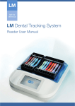
CombiLED DVD/CD-R USERMANUAL MANUAL USER This manual is valid for: LM-ProPower 100722 LM-ProPower 100732 LM-ProPower 100722us LM-ProPower 100732us LM-ProPower 100722jp LM-ProPower 100732jp Important! Read this manual carefully before using the product. How to read this manual Each chapter starts with a section with general instructions, which is followed by sections with additional information. First read the general section and then proceed to the section that applies to your product. If there are any questions regarding the contents of this manual, please contact LM-Instruments Oy. Manufacturer, Marketing and Sales LM-Instruments Oy PL 88 (Norrbyn rantatie 8) FI-21601 Parainen. Finland Telephone: +358 2 4546 400 Fax: +358 2 4546 444 E-mail: [email protected] Internet: www.lminstruments.com Copyright Copyright 2010 LM-Instruments Oy. All rights reserved. The contents of this manual may be changed without notice. No part of this manual may be reproduced in any form or by any means without permission in writing from LM-Instruments Oy. Printed in Sweden, January 2010. 2 0537 Contents Safety . ................................................................................... 5 Consignes de securite (Canada) . ....................................... 7 1 Unpacking ..................................................................... 9 1.1 General content of delivery ............................................. 9 1.2 Content of introkits ......................................................... 10 2 Equipment description ................................................. 1 1 2.1 General description . ....................................................... 11 2.2 Control panel.................................................................... 12 2.3 ProPower foot control ..................................................... 13 2.4 Medicament bottle .......................................................... 14 2.5 Symbols on the equipment ............................................. 15 3 Installation ..................................................................... 16 3.1 General installation instructions ...................................... 16 3.2 Version for tap water ...................................................... 17 3.3 General installation instructions, continued .................... 17 4 Operating instructions ................................................. 18 4.1 General ........................................................................... 18 5 Cleaning and maintenance .......................................... 21 5.1 General cleaning procedure ........................................... 21 5.2 Recommended cleaning procedure ................................ 22 5.3 Maintenance ................................................................... 23 6 Troubleshooting . .......................................................... 24 7 Technical data ............................................................... 25 8 Warranty and Declaration of conformity .................... 27 8.1 Warranty ......................................................................... 27 8.2 Declaration of conformity ................................................ 28 8.3 EMC - guidance . ............................................................. 29 3 4 Safety Safety Intended use This AirLED polisher unit is designed for dental purposes. It is designed for removal of plaque, cleaning discoloured teeth and other dental work where air polishing is beneficial. The unit should only be used by licensed dental proffesionals trained in the proper use of polishing devices. Do not use it for applications where it is not intended. If you are unsure about your application, please contact your local dealer or place of purchase. General requirements Installation and service of the product is only to be performed by authorized service personnel. The product must be connected to electricity-, water- and compressed air supply meeting the requirements specified in the Technical data section on page 25. The product needs special precautions regarding EMC (Elektro Magnetic Compability) and needs to be installed and put into service according to the EMC information provided on page 29. Portable and mobile RF (Radio Frequency) communications equipment can affect the product. General precautions • • If the handpiece tubing is damaged or worn-out, it must immediately be replaced to avoid exposing the user or the patient to elec- tric hazard. Use the original packaging when returning equipment for service. Warnings The product should not be used adjacent to or stacked with other equipment. If adjacent or stacked use is necessary, the product should be observed to verify normal operation in the configuration in which it will be used. 5 Safety Safety notices in this manual WARNING Caution Warning indicates a potentially dangerous situation. Non-observance may lead to death or injury. Caution indicates a potentially harmful situation. Non-observance may damage the equipment. Note indicates a situation where special notice should be observed. Note 66 Consigne de sécurité Consigne de sécurité (Canada) Utilisation prévue Cet appareil aéropolisseur, AirLED, est destiné à des applications dentaires. Il est conçu pour éliminer le plaque, biofim, des taches et décolorations des dents et pour toute autre application dentaire où l’aéropolissage est bénéfique. Cet appareil doit être exclusivement manipulé par des professionnels dentaires diplômés ayant suivi une formation relative à l’utilisation correcte des dispositifs de détartrage. N’employez pas cet appareil pour des applications pour lesquelles il n’est pas conçu. Au cas où vous ne seriez pas sûr de son application, veuillez contacter votre distributeur local ou le point de vente. Conditions générales L’installation et le service du produit doit être executé seulement par le personnel de service autorisé avec les outils et le matériel appropriés. Le produit doit être relié à l’approvisionnement de l’électricité et à l’approvisionnement en eau et en air comprimé répondant aux exigences définies dans la section Caractéristiques techniques à la page 25. Le produit exige des précautions spéciales concernant la CEM (Compatibilité Electromagnétique) et doit être installé et mis en service selon à la page 29. L’équipement de communication RF (Radio Fréquence) portable et mobile peut affecter le produit. Précautions générales • • Si la tuyauterie de pièce à main est endommagée ou usée, elle doit immédiatement être substituée pour éviter d’exposer l’utilisateur ou le patient au risque électrique. Utilisez l’original empaquetage en renvoyant le matériel pour le service. Avertissement Le produit ne doit pas être utilisé à proximité ou empilé avec d’autres équipements. Si l’usage adjacent ou empilé est nécessaire, le produit doit être surveillé pour une utilisation normale suivant la configuration dans laquelle il sera utilisé. 7 Consigne de sécurité Notifications de sûreté en ce manuel WARNING “Warning” indique une situation probablement dangereuse. La inobservance peut mener à la mort ou des dommages. “Caution” indique une situation probablement nocive. La inobservance peut endommager le matériel. Caution “Note” décrit si on observe la notification spéciale. Note 68 1 Unpacking Caution Caution indicates a potentially harmful situation. Non-observance may damage the equipment. Unpacking Carefully unpack your LM-ProPower AirLED unit and verify that all accessories components are included Note and indicates a situation where according to the content lists below:special notice should be observed. 1.1 General content of delivery Note This chapter describes the components of the delivery and can be used as a check list when unpacking. Contact your place of purchase if anything is missing. For a description of the features of the equipment, read the Equipment description section on page 11. 1. LM-ProPower AirLED unit 2. Polisher introkit (see section 1.2) 3. 500 ml medicament bottle or water hose 1/4” 4. Air hose 5. Powder container + Polisher handpiece and tubing 6. ProPower foot control 7. Foot control cable 8. Power cord 4 3 8 7 2 5 3 6 6 1 9 Unpacking 1.2 Content of introkit Content of AirLED Polisher introkit 2 x Polisher nozzles (universal and angeled) 2 x ErgoGrips (Light, Focus Light) 2 x Bottles 180 g polisher powder Universal Angeled 10 Equipment description 2 Equipment description 2.1 General description LM-ProPower AirLED is an effective AirLED polisher in one versatile and ergonomic appliance. The device is equipped with the impressive LED-light that gives an optimal visibility in diagnostics and removal of discolourings and stains. Ergonomically designed ErgoGrip handpieces with soft silicone handles give the user a comfortable, relaxed grip as well as an excellent feel. 4 3 7 8 1 1. Polisher handpiece (with an ErgoGrip and a nozzle mounted) 2. Handpiece tubing 3. Powder container 4. Water flow control ring 5. Control panel 2 6. ProPower foot control 7. Medicament bottle 8. Depressurisation button 5 6 11 Equipment description 1. AC power input 2. Fuse holder 3. Air hose coupling 4. Water hose coupling (optional) 5. Foot control connection 6. Type plate 6 2 5 3 1 4 2.2 Control panel 14 1 1. Cleaning key 2. Power on key 3. Power off key 13 6 4. Air-Purge key 5. Working mode 2 key = 60% power 12 5 6. Working mode 3 key = 60 or 100% power 7. StandBy indicator 9 11 4 10 8. Power on indicator 9. Air-Blow mode indicator (polisher) 10. Water-Jet mode indicator (polisher) 8 11. Air-Purge indicator 12. Working mode 2 indicator 13. Working mode 3 indicator 14. Cleaning mode indicator 2 12 7 3 Equipment description 2.3 ProPower foot control 1. Connection for foot control cable 2. OFF position 3. ON position 4. Diagnostic function, turn LED light ON or OFF by a single-click on the pedal 5. Water Jet position 6. Working mode 3 position if working mode 3 is chosen on control board, otherwise working mode 2 7. Working mode 2 position 1 2 4 3 6 5 7 13 Equipment description 2.4 Medicament bottle (optional) LM-ProPower has a medicament dispenser system, making the device independent of a fixed water supply connection. The medicament bottle can be used for either medicament solutions or ordinary clean water. The unit contains an electrically driven air compressor. When operating the unit the compressed air forces the fluid from the bottle through the hose and to the handpiece and the tip/nozzle. 1. Medicament bottle 2. Bottle connector 3. Depressurisation button 2 1 3 The LM-ProPower can be delivered either with the medicament dispenser system or with fixed water supply connection without the bottle and bottle connector. 14 Equipment description 2.5 Symbols on the equipment Air-Purge Working mode 2 = 60% power Working mode 3 = 60 or 100% power Water-Jet mode Air-Blow mode Automatic cleaning function Power ON Power OFF Example of type plate. The type plate is placed on the back side of the scaler unit. CLASSIFIED 9800163 Medical electrical equipment classified by ETL with respect to electric shock, fire, mechanical, and other specified hazards in accordance with the Safety Standards ANSI/AAMI ES 60601-1 and CAN/CSA C22.2 No 60601-1:08 Caution Consult accompanying documents. 0537 Compliance label indicating compliance with the Medical Device Directive 93/42/EEC. 0537 is the ID-number of the Notified Body: VTT Withstands autoclave temperature 135°C (275°F). Type B applied part according to the degree of protection against electrical shock. Fuse Input Output Please do not throw the equipment into the domestic refuse. Please use the return and collection systems available in your country for the disposal of this product. The equipment can also be returned to the manufacturer for disposal. 15 Installation 3 Installation WARNING 3.1 General installation instructions Checklist • Position the unit horizontally with the handpieces in the holders and the hoses hanging free. • Position the unit where air is free to circulate on all sides and beneath it. Do not position the unit on a wall or next to a heat source. • Avoid placing the unit in the immediate vicinity of sources of electromagnetic radiation, for example an electrosurgery equipment. • Connect the foot control cable to the foot control and at the rear side of the unit. Caution Caution Do not place the unit on or next to a heat source. Excessive heat may damage the electronics. Note WARNING Connecting to the air supply 1. Verify that the air supply can be turned off. 2. Verify that the air pressure conforms to the data in the Technical data section on page 25. 3. Use only dry and filtered com-pressed air. 4. Unscrew the nut from the nipple and thread it on the hose. 5. Push the hose onto the coupling nipple. Caution Caution Consult a qualified technician for connecting the unit to the air supply. Use only dry and filtered compressed air. Note 6. Tighten the nut firmly and ensure that the hose is securely attached to the unit. 7. Connect the other end of the hose to the air supply. 6 16 Installation WARNING Caution Caution Consult a qualified technician for connecting the scaler to the water supply. Note 3.2 Version for tap water (optional) Connecting to the water supply 1. Verify that the water supply can be turned off. 2. Verify that the water pressure conforms to the data in the Technical data section on page 25. 3. Verify that the water supply fulfills the medical demands of hygiene. 4. Unscrew the nut from the nipple and thread it on the hose. 5. Push the hose onto the coupling nipple. 6. Tighten the nut firmly and insure that the hose is securely attached to the unit. 7. Connect the other end of the hose to the water supply. Safety notices in this manual WARNING Caution WARNING The unit must be connected to an AC power outlet provided with a protective ground. USA and Canada: The power cord and plug must be classified as ”Hospital-Grade”.Note Warning indicates a potentially dangerous situation. Non-observ3.3ance General may lead toinstallation death or injury. continued instructions, • Verify that the voltage rating on the rear side match the voltage ofCaution the AC power outlet. indicates a potentially • Verify thatsituation. the AC power outlet is provided with a protective harmful Non-observground. ance may damage the equipment. • Connect the power cord to the unit and the AC power outlet. All indicator lamps will illuminate for a short period during a self check of the unit. Note a situation • The unitindicates is standby when thewhere green indicator lamp is illuminated. special notice should be observed. 6 17 Operating instructions 4 Operating instructions Preparations (bottle version) 1. Fill the medicament bottle with water or medicament solution according to the Medicaments that can be used section on page 25. Safety notices in this m 2. Screw the bottle connector onto the bottle and push it onto the connector. See picture in section 2.4 WARNING 3. Check that the unit is connected to air supply, the power cord is connected and the unit is in stand-by mode, the green indicator lamp is illuminated. 4.1 General Caution 1. Unscrew the powder container from the cap and fill the powder container with LM-ProPower powder up to MAX. Note Only use original LM-ProPower air polishing powder. WARNING 2. Screw the container back on to the cap and connect the tubing to the cap. Caution Caution It is important, that the powder container is fully tightened before the polisher is activated. Do not leaveNote powder in the powder container over the night. 3. Connect the powder container cap to the connectors on the right side of the unit. 4. Connect the medicament bottle to the unit, see instruction section 2.4 (bottle version). 18 6 Wa dan anc Cau har anc Not spe serv Operating instructions WARNING 5. Gently slide the ErgoGrip on to the polisher handpiece. Caution Caution Safety notices It is very important, that the in this manual polisher not is activated before the nozzle is mounted. Note 6. Insert the polisher nozzle into the handpiece until the bottom. Warning indicates a potentially dangerous situation. Non-observance may lead to death or injury. SafetyWARNING notices in this manual WARNING Caution WARNING When inserting the nozzle it is important to push it in until the bottom is reached. Caution Note Note For the polisher only working mode 2 and 3 can be activated. Working mode 2 is aprox. 60% of polishing power compared to working mode 3 (100%). Working mode 1 can not be activated. WARNING Warning indicates potentially 7. Turn on theindicates polisheraaon by pressing the button marked ON on Caution potentially dangerous situation. Non-observtheharmful front side of the scaler. The blue polisher indicator lamp situation. Non-observlead to death or injury. illuminates. ance may damage the equipment. 8. Choose working mode 2 or 3 by pressing the corresponding working mode key on the keyboard (see note). 9. A second press of the ON key activates the Air-blow mode for Caution indicates a potentially Note indicates situation where cleaning with justa air. harmful situation. Non-observspecial notice should be ob10. A ance thirdmay pressdamage of the ON key activates the Water-Jet cleaning mode. the equipment. served. No powder, but only water and air, comes out from the nozzle. The Water-Jet mode can also be activated in the scaling mode by pressing down the foot control in the leftmost position. 11. ByNote pressing the ON key repeatedly, indicates a situation where it will toggle between normal polishing-, Air-blowand Water-Jet mode. special notice should be observed. 12. Point the handpiece towards the cuspidor and over the bowl. Depress the foot switch to activate the polisher and adjust the water flow with the ring on the powder container, see equipment description. 13. Hold the polisher nozzle approximately 1 cm (0,4 in.) downright from the bottom of the bowl and press the foot control to activate the polisher. 14. Slowly reduce the water flow until the powder starts to accumulate on the surface as a white spot. 15. Increase the water flow until the spot just disappears. The air polisher is now balanced for optimum performance. 16. Perform polishing treatment according to “How to use the polisher” section on next page. Water-Jet cleaning 6 Caution Caution It is very important to air purge the polisher handpiece after each treatment to prevent clogging. Note With the foot control pressed down in the leftmost position the “Water-jet” cleaning mode is activated and no powder, but only water and air, comes out from the nozzle. 19 Operating instructions WARNING Polishing power With working mode 3 choosen and the foot control is pressed down in the rightmost position the unit will temporarely switch to working mode 2 (the polishing power is reduced to aprox. 60%). Air purge quick cleaning function With the polisher mode active, a press on the ”AP” button will air purge the handpiece for a few seconds. Air purge the handpiece after each treatment to prevent clogging. How to use the AirLED polisher Polishing is suitable for the following procedures: • Efficient removal of heavy stains and dental plaque. • Cleaning teeth prior to bleaching. • Cleaning pits and fissures prior to sealant placement. • Surface cleaning prior to any acid etch or bonding procedure. • Cleaning orthodontically banded or bracketed teeth. • Cleaning of implants. 1. Protective eyewear should be worn by the patient and operator. Contact lenses should not be worn, or a close fitting eye shield should be provided. 2. The jet should be kept constantly moving in small circles. It should not be directed at the same spot too long. The nozzle shall be held approximately 3 mm (0,12 in.) from the surface. 3. The polisher will be most effective when directing the jet downright towards the tooth although the spray should be directed away from the gingiva onto the tooth. 4. Only one or two teeth should be polished at a time, with frequent rinsing performed. An efficient intraoral evacuation system will prevent excessive build-up of fluid and increase patient comfort. A short learning period is required by the operator, as with any new technique, until the ideal angulations, soft tissue protection and an effective treatment can be achieved. Caution WARNING Polishing should NOT be performed on patients who: • Are on a sodium restricted diet. • Have renal insuffiency. • Have chronic respiratory disease. Note • Are on long term steroid or diuretic therapy. 20 Ca har anc Safety notices in thisNom WARNING Caution WARNING Especially when using a sodium bicarbonate cleaning powder, the spray should never be directed into the gingival sulcus or onto the gingival margin, as this can result in unnecesNote sary abrasion of the gingival tissues and/or extension of the periodontal pocketing, with associated clinical complications. Caution should be exercised in dealing with dentine surfaces, root cement and composite fillings. WARNING After treatment 1. Without removing the nozzle, place the polisher handpiece over the bowl and press the air purge key ”AP”. 2. The polisher air purges the handpiece for a few seconds. 3. After the cleaning cycle is finished, remove the nozzle by pulling it out from the handpiece. 4. Wash the nozzle in an ultrasonic bath (40-50°C), for at least 3 minutes, before cleaning/sterilization. If ultrasonic cleaning not is possible, flush the nozzle in warm water. 5. Squeeze the ErgoGrip gently at the top and at the same time slide it off the handpiece. Do not squeeze too hard at the ErgoGrip as this can make the removal difficult. 6. Remove the powder container and polisher handpiece. 7. Before removing the medicament bottle, press the depressurization button. 8. Pull the medicament bottle from the unit. 9. Clean and sterilize the equipment /components according to the Cleaning and maintenance section on page 21-23. Wa dan anc Caution Caution It is important to air purge the handpiece after each treatment to prevent clogging. must always Note 6 The air purge be performed with the polisher nozzle mounted in the handpiece. Do not leave powder in the powder container over the night. spe ser Wa dan anc Ca har anc No spe ser WARNING ance may lead to death or injury. Caution indicates a potentially harmful situation. Non-observance may damage the equipment. Cleaning and maintenance 5 Cleaning and maintenance Caution 5.1 General cleaning procedures Air purge quick cleaning function Note Always set the water flow to fully open before running the cleaning cycle (dots in line, see picture). Note indicates situation where With the polisher modeaactive, a press on the ”AP” button will air purge the special notice should be obhandpiece for a few seconds. Air purge the handpiece after each treatment served. to prevent clogging. Automatic cleaning function 1. Place the polisher handpiece over the bowl and start the cleaning cycle by pressing the cleaning key “C”. 2. The cleaning cycle starts and stops automatically after 80 seconds. Cleaning of the equipment/components WARNING Wipe off with a soft cloth and use a 45% isopropanol and detergent solution Cover and control panel Caution Caution The automatic cleaning function must always be performed with the polisher nozzle mounted in the handpiece. Note Polisher handpiece, tubings and cables Cap for powder container Wash at max 65°C (149°F) Powder container Medicament bottle 6 Cap for medicament bottle 21 Cleaning and maintenance Caution Autoclave in steam at max 135°C (275°F) or wash at max 95°C (203°F) Polisher nozzle Note Always set the water flow to fully open before running the cleaning cycle (dots in line, see picture). LM-ErgoGrip LED LM-ErgoGrip Focus LED WARNING 5.2 Recommended cleaning procedure Beginning of the day Run the automatic cleaning cycle with clean water. See instructions on page 21. Caution Caution After each treatment • To prevent clogging, air purge the polisher handpiece after each treatment. See instructions on page 20. • Run the automatic cleaning cycle with clean water. See instructions on page 21. • Wipe off the cover, control panel, handpiece and the hose with a soft cloth. Use a 45% isopropanol and detergent solution. • Wash the nozzle in an ultrasonic bath (40-50°C), for at least 3 minutes, before cleaning/sterilization. If ultrasonic cleaning not is possible, flush the nozzle in warm water. • Wash the ErgoGrip, the nozzle and autoclave according to the clinic’s routines. End of the day • Run the automatic cleaning cycle with clean water. See instructions on page 21. • Remove and wash medicament bottle, bottle cap and powder container at a maximum temperature of 65°C (149°F). • Wipe of the powder container cap with a soft cloth. Use a 45% isopropanol and detergent solution. 22 Do not sterilize any accessories using dry heat or chemical autoclaves. This may damage the material. Do not immerse the handpiece in any fluid. Note 6 Ca ha an No spe ser Cleaning and maintenance Weekly (bottle version) • Run the automatic cleaning cycle with an anti-microbial cleaning agent solution in the bottle, for example Planosil. See instructions on page 21. We recommend to use a separate bottle for the cleaning agent solution. Concerning exposure times of cleaning agent, follow instructions given by manufacturer. • Before patient treatment; to rinse the lines from cleaning agent solution put clean water in the bottle and run the automatic cleaning cycle until clean water comes out of the handpiece. 5.3 Maintenance WARNING Caution Caution A petroleum based lubricant on the o-rings may shorten their durability time. Power cord Inspect the power cord, cables and the handpiece hose daily to insure that the equipment is in good condition without mechanical damage. O-rings (bottle and powder container connectors, polisher nozzle) Lubricate the O-rings regularly with a glycerine based, water soluble lubricant. Vaseline may also be used, but it may shorten the durability time of the O-rings. Exchanging fuses 1. Disconnect the power cord from the AC power outlet and the unit. 2. Open the fuse holder on the rear side of the unit. Note 3. Inspect the fuses for damages. Replace damaged fuses with new ones. Verify the fuse specifications according to the Technical data section on page 25. 4. Close the fuse holder. 23 Troubleshooting 6 Troubleshooting 6.1 General Problem Action The green Stand-by indicator lamp is off. Check that the power cord is connected properly. Check the fuses and replace if necessary. For further instruction, read the Exchanging fuses section on page 23. The blue power ON indicator is flashing Check that the foot control cable is connected in both ends and is not defective. There is a stop in the polisher nozzle and no air and powder is coming out from the nozzle. Place the nozzle in an ultrasonic bath with WARM water for a couple of minutes. Flush the nozzle in water and dry it with compressed air, reconnect and try again. It is difficult to insert the polisher nozzle into the handpiece. Check that the o-rings on the polisher nozzle are lubricated and in good condition. If problems cannot be resolved according to this troubleshooting guide, please contact your dealer for further service support. 24 Technical data 7 Technical data Manufacturer LM-Instruments Oy PL 88 (Norrbyn rantatie 8) FI-21601 Parainen, FINLAND Model LM-ProPower AirLED Classification EN60601-1: Class 1, Type B 93/42 EU: Medical products, class IIa L x W x H 270 x 110 x 165 mm (without bottle and powder container) Weight 3200 g Voltage 100 Vac, 50-60 Hz 115 Vac, 50-60 Hz 230 Vac, 50-60 Hz Primary fuse T500 mAH, 250 V, Ø5x20 mm (100 Vac) T400 mAH, 250 V, Ø5x20 mm (115 Vac) T200 mAH, 250 V, Ø5x20 mm (230 Vac) Power cord Separate with protective earth plug Power consumption Max. 40 VA Ambient temperature Transport and storage -40°C to 70°C (-40°F to 158°F) Relative humidity Transport and storage 10% to 100% Operation 10°C to 40°C (50°F to 104°F) Operation 10% to 95% Water supply pressure (version conn. to tap water) 1 - 10 bar (0,1–1,0 MPa, 14,5–145 PSI) Water consumption 10 - 50 ml/min Bottle volume (bottle version) 500 ml Air supply pressure 4 - 10 bar (0,4 - 1,0 MPa, 58 - 145 PSI) Use only dry and filtered compressed air. Air consumption Max. 20 l/min Powder container capacity 45 g Installation and service of the product is only to be performed by authorized service personnel by the manufacturer. 25 WARNING Technical data Medicaments that can be used • • • • • • • • • • Clean water Cetylpyridinium chloride Clorhexidine Essential oils Hydrogen peroxide, 3% USP Povidine iodine, 10% solution Saline solution Sangurinara extract Planosil, Oxygenal and Dentosept (for unit cleaning) Sodium hypochlorite 1% solution Caution WARNING Immedately after using any kind of medicament in the medicament bottle, run the automatic cleaning cycle with clean water in the medicament bottle until clean water comesNote out of the handpieces. 6 26 War dan anc Cau har anc Not spe serv Warranty and declaration 8 Warranty and Declaration of conformity 8.1 Warranty The manufacturer hereby warrants that the unit will be free from defects arising from faulty materials or workmanship for a period of twentyfour (24) months from the date of purchase by a customer from an authorized dealer (“Limited Warranty”). This Limited Warranty is limited to, free of charge, repair or replacement of any defective parts by the authorized dealer or distributor from whom the unit was purchased by the customer. This Limited Warranty applies only if the unit is installed and used by the customer according to the instruction furnished herein, is connected to a proper power supply, is not misused or abused, and there is no evidence of tempering, mishandling, neglect, accidental or wilful damage or modifications. The customer must contact the authorized dealer from whom the unit was purchased to request repair or replacement under this Limited Warranty. This Limited Warranty is void if service or repair is performed by persons not authorized by the manufacturer. Normal wear and tear is specifically excluded from this Limited Warranty. Manufacturer disclaims any express warranty not provided herein and any implied warranty, guarantee or representation as to suitability for any particular purpose, performance, quality, and absence of hidden defects, and any remedy for breach of contract, which but for this provision, might arise by implication, operation of law, custom of trade, or course of dealing, including implied warranties of merchantability and fitness for a particular purpose, except as provided in this limited warranty. The manufacturer further disclaims any responsibility for losses, expenses, inconveniences, special, indirect, secondary, or consequential damages arising from ownership or use of the product. 27 WARNING Warranty and declaration 8.2 Declaration of conformity The manufacturer hereby declares that the LM-ProPower AirLED unit Class I, type B according to EN60601-1 equipped with original accessories conforms to the essential requirements of the Medical Device Directive 93/42/EEC with reference to the following harmonized standards: Caution WARNING Cau har anc No modification of this equipment is allowed. IEC 60601-1, Third edition 2005 EN 60601-1: 2006 Note Classification: Medical products, Class IIa: 0537 6 28 Wa dan anc Not spe serv Warranty and declaration 8.3 EMC - Guidance and manufacturer’s declaration Guidance and manufacturer's declaration - electromagnetic emissions The LM-ProPower is intended for use in the electromagnetic environment specified below. The customer or the user of the LM-ProPower should assure that it is used in such an environment. Emission test Compliance Electromagnetic environment - guidance RF emissions CISPR 11 Group 1 The LM-ProPower uses RF energy only for its internal function. Therefore, it's RF emissions are very low and are not likely to cause any interference in nearby electronic equipment. RF emissions CISPR 11 Class B Harmonic emissions IEC 61000-3-2 Not applicable Voltage fluctuations/ flicker emissions IEC 61000-3-3 Not applicable The LM-ProPower is suitable for use in all establishments, including domestic establishments and those directly connected to the public low-voltage power supply network that supplies buildings used for domestic purposes. Guidance and manufacturer's declaration - electromagnetic immunity The LM-ProPower is intended for use in the electromagnetic environment specified below. The customer or the user of the LM-ProPower should assure that it is used in such an environment. IEC 60601 test level Immunity test Electrostatic discharge (ESD) Compliance level ±6 kV contact ±6 kV contact ±8 kV air ±8 kV air ±2 kV for power supply lines ±2 kV for power supply lines ±1 kV for input/output lines ±1 kV differential mode ±1 kV for input/output lines ±1 kV differential mode ±2 kV common mode ±2 kV common mode Voltage dips, short interruptions and voltage varaiations on power supply input lines <5 % U T (>95 % dip in UT) for 0,5 cycle <5 % U T (>95 % dip in UT) for 0,5 cycle 40 % U T (60 % dip in UT) for 5 cycles 40 % U T (60 % dip in UT) for 5 cycles IEC 61000-4-11 70 % U T (30 % dip in UT) for 25 cycles 70 % U T (30 % dip in UT) for 25 cycles <5 % U T (>95 % dip in UT) for 5 sec <5 % U T (>95 % dip in UT) for 5 sec 3 A/m 3 A/m IEC 61000-4-2 Electrical fast transient/burst IEC 61000-4-4 Surge IEC 61000-4-5 Power frequency (50/60 Hz) magnetic field Electromagnetic environment guidance Floors should be wood, concrete or ceramic tile. If floors are covered with synthetic material, the relative humidity should be at least 30%. Mains power quality should be that of a typical commercial or hospital environment. Mains power quality should be that of a typical commercial or hospital environment. Mains power quality should be that of a typical commercial or hospital environment. If the user of the LM-ProPower requires continued operation during power mains i interruption, it is recommended that the LM-ProPower be powered from an uninterruptible power supply or battery. Power frequency magnetic fields should be at levels characteristic of a typical location in a typical commercial or hospital environment. IEC 61000-4-8 NOTE U T is the a.c. mains voltage prior to application of the test level. 29 Warranty and declaration Guidance and manufacturer's declaration - electromagnetic immunity The LM-ProPower is intended for use in the electromagnetic environment specified below. The customer or the user of the LM-ProPower should assure that it is used in such an environment. Immunity test IEC 60601 test level Compliance level Electromagnetic environment - guidance Portable and mobile RF communications equipment should be used no closer to any part of the LM-ProPower including cables, than the recommended separation distance calculated from the equation applicable to the frequency of the transmitter. Recommended separation distance Conducted RF 3 Vrms IEC 61000-4-6 150 kHz to 80 MHz Radiated RF 3 V/m IEC 61000-4-3 80 MHz to 2,5 GHz 3V d = 1,2√P 3 V/m d = 1,2√P 80 MHz to 800 MHz d = 2,3√P 800 MHz to 2,5 GHZ were P is the maximum output power rating of the transmitter in watts (W) according to the transmitter manufacturer and d is the recommended separation distance in metres (m). Field strengths from fixed RF transmitters as determined by an electromagnetic site survey, a should be less than the compliance level in each frequency range.b Interference may occur in the vicinity of equipment marked with the following symbol: NOTE 1 At 80 MHz and 800 MHz, the higher frequency range applies. NOTE 2 These guidelines may not apply in all situations. Electromagnetic propagation is affected by absorption and reflection from structures, objects and people. a b 30 Field strengths from fixed transmitters, such as base stations fro radio (cellular/cordless) telephones and land mobile radios, amateur radio, AM and FM radio broadcast and TV broadcast cannot be predicted theoretically with accuracy. To assess the electromagnetic environment due to fixed RF transmitters. an electromagnetic site survey should be considered. If the measured field strength in the location in which the LM-ProPower is used exceeds the applicable RF compliance level above, the LM-ProPower should be observed to verify normal operation. If abnormal performance is observed additional measures may be necessary, such as reorienting or relocating the LM-ProPower. Over the frequency range 150 kHz to 80 MHz, field strengths should be less than 3 V/m. Warranty and declaration Recommended separation distances between portable and mobile RF communications equipment and the LM-ProPower The LM-ProPower is intended for use in an electromagnetic environment in which radiated RF disturbances are controlled. The customer or the user of the equipment can help prevent electromagnetic interference by maintaining a minimum distance between portable and mobile RF communications equipment (transmitters) and the LM-ProPower as recommended below, according to the maximum output power of the communications equipment. Separation distance according to frequency of transmitter m Rated maximum output power of transmitter W 150 kHz to 80 MHz 80 MHz to 800 MHz 800 GHz 150MHz kHz to 2,5 80 MHz d = 1,2√P d = 1,2√P d = 2,3√P 0,01 0,12 0,12 0,23 0,1 0,38 0,38 0,73 1 1,2 1,2 2,3 10 3,8 3,8 7,3 100 12 12 23 For transmitters rated at a maximum output power not listed above, the recommended separation distance d in metres (m) can be estimated using the equation applicable to the frequency of the transmitter, where P is the maximum output power rating of the transmitter in watts (W) according to the transmitter manufacturer. NOTE 1 At 80 MHz and 800 MHz, the separation distance for the higher frequency range applies. NOTE 2 These guidelines may not apply in all situations. Electromagnetic propagation is affected by absorption and reflection from structures, objects and people. 31 32 33 34 35 LM-Instruments Oy 9770090 9770036-C PL 88 (Norrbyn rantatie 8) FI-21601 Parainen Finland Tel. +358 2 4546 400 Fax +358 2 4546 444 [email protected] www.lminstruments.com