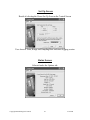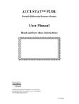
1
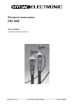
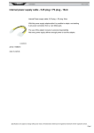
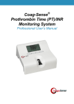
ACCUSTAT™ P2/DL
Portable Differential Pressure Monitor
User Manual
Read and Save these Instructions
Manufactured by
749 Hope Road, Suite A- Eatontown, NJ 07724 USA
Tel: 800-224-9768, 732-389-8922 Fax: 732-389-8821
www.biologicalcontrols.com
3/12/2014
SAFETY INSTRUCTIONS
Read and Save these Instructions
Understanding the signal words: DANGER, WARNING and CAUTION.
These words are universally used for overall safety:
•
•
•
Signifies the most serious hazards, which will result in severe
personal injury or death.
Signifies hazards, which could result in personal injury or death.
Signifies unsafe practices, which would result in minor personal
injury or product and property damage.
READ INSTRUCTION MANUAL THOROUGHLY AND FOLLOW ALL
DANGER, WARNING OR CAUTION NOTES AND LABELS ATTACHED TO THE UNIT
BEFORE STARTING INSTALLATION OR MAINTENANCE ACTIVITIES.
IMPROPER INSTALLATION, ADJUSTMENT, ALTERATION, SERVICE,
MAINTENANCE, OR USE CAN CAUSE FIRE, ELECTRICAL SHOCK, OR OTHER
CONDITIONS THAT MAY CAUSE PERSONAL INJURY OR PROPERTY DAMAGE.
WEAR SAFETY GLASSES AND WORK GLOVES AND FOLLOW ALL SAFETY LOCAL
BUILDING AND ELECTRICAL CODES. CONSULT A QUALIFIED INSTALLER,
SERVICE AGENCY OR YOUR SUPPLIER FOR INFORMATION OR ASSISTANCE.
Copyright 2011 Biological Controls
3/12/2014
Standard P2
Copyright 2011 Biological Controls
Data Logger P2/DL
3/12/2014
Table of Contents
Section:
Page #
1.
INTRODUCTION...................................................................................................................................1
2.
2.1.
2.2.
2.3.
2.4.
2.5.
2.6.
OPERATION and SET-UP ....................................................................................................................1
Quick-Reference Instruction Guide .......................................................................................................1
Power.......................................................................................................................................................1
Battery LED............................................................................................................................................1
Battery Status..........................................................................................................................................1
Meter Range (Units) ...............................................................................................................................2
Meter ZERO Adjustment/Calibration ...................................................................................................2
3.
3.1.
3.2.
3.3.
3.4.
3.5.
3.5.1.
3.5.2.
3.6.
PRESSURE ALERT FUNCTION ..........................................................................................................2
Alert Select Switch..................................................................................................................................2
Basic Set-Up:...........................................................................................................................................2
Alert Mode Switch ..................................................................................................................................3
Alert Set-Point Adjustment.....................................................................................................................3
Typical Pressure Alert Set-Up Examples:..............................................................................................3
Negative-Pressure ...................................................................................................................................3
Positive-Pressure .....................................................................................................................................3
Audible Mute...........................................................................................................................................3
4.
4.1.
4.2.
4.3.
4.4.
MAINTENANCE INFORMATION.......................................................................................................4
General....................................................................................................................................................4
Cleaning ..................................................................................................................................................4
Calibration ..............................................................................................................................................4
Battery-Pack Replacement .....................................................................................................................4
5.
5.1.
5.2.
5.3.
5.3.1.
5.3.2.
5.3.3.
DATA LOGGER ACCUSTAT™ P2/DL ...............................................................................................5
Software Set-Up ......................................................................................................................................5
Data Log Status LEDs.............................................................................................................................5
Log Function Switch ...............................................................................................................................6
Log-Mode ................................................................................................................................................6
Suspend-Mode .........................................................................................................................................6
Logging Session .......................................................................................................................................6
5.4.
Retrofit Option........................................................................................................................................6
6.
6.1.
WARRANTY ..........................................................................................................................................7
Making a Warranty Claim.....................................................................................................................7
7.
7.1.
Appendix A..............................................................................................................................................8
Examples of Suspend-Mode ....................................................................................................................8
8.
8.1.
Appendix B..............................................................................................................................................9
Software Interface Screen-Views ...........................................................................................................9
9.
9.1.
Appendix C............................................................................................................................................12
Battery Conditioning Suggestions.........................................................................................................12
10.
SPECIFICATIONS...............................................................................................................................13
Copyright 2011 Biological Controls
3/12/2014
ACCUATAT P2™ Portable Differential Pressure Monitor
1.
INTRODUCTION
The ACCUSTAT™ P2 is the next generation of the ACCUSTAT™ P1 Portable Differential
Pressure Monitor. The new models feature a rugged water tight, lockable enclosure, over 48 hours
of operational-time when powered by the rechargeable battery, and a data-logging option. All
accessories fit within the enclosure storage compartments. There are two models to choose from
the P2 and the P2/DL.
See the Specifications Section for a listing of features and functions.
Sampling Medium: Air or non-corrosive, non-explosive gas only
Do Not Exceed Overload Pressure: ±138” WC or ±34K Pa Maximum
2.
OPERATION and SET-UP
The user interface is divided into functional groupings outlined in white silk-screened areas on the
enclosure panels and these are described below.
2.1.
Quick-Reference Instruction Guide
The guide is silk-screened onto the face of the storage-pocket located in the lid of the enclosure.
Refer to the information to set-up and operate the unit. The lid storage area is used to store the
black sample-tubing and the USB cable (for Data Logger option).
2.2.
Power
The unit will operate on the 12VDC power-module included in the accessory pack, or on the
internal NiMh battery. Before battery-operation is anticipated, plug the power-module into a 100240VAC wall outlet (international plug adaptors are supplied in the accessory kit) and connect the
smaller 12VDC end of the cable into the ACCUSTAT™P2 power plug (located on the side-panel in
the storage compartment). The Accustat™P2 does not need to be turned- on for the battery to
charge.
2.3.
Battery LED
The green Battery LED illuminates until the battery-charge circuits go into the trickle-charge mode.
The LED may not light when the power-module is first plugged-in if the charging circuits are in this
mode. Disconnecting the 12VDC power plug and reinserting it will force the normal-charge mode
and illuminate the LED. When the LED turns-off the battery continues to trickle-charge to 100%;
therefore, leave the charger in place for several hours more to obtain optimum battery usage-time.
2.4.
Battery Status
When the Battery-Status push-button is depressed the %-of-charge is displayed. A fully charged
battery will deliver 48+ hours of use. When the charge is very low a “BAT” symbol appears in the
LCD display. When this occurs the unit must be connected to the power-module to recharge the
battery to avoid halting an active data logging session.
See Appendix C for Battery Conditioning instructions.
Copyright 2014 Biological Controls
1
3/12/2014
2.5.
Meter Range (Units)
The Accustat™P2 can display pressure-units in either PASCAL’s (Pa) or Water Column (WC).
These units both have High and Low pressure ranges (specified on the silk-screened enclosure
storage-panel and also shown in the Specifications Section).
Set the two (2) Range Switches before performing the Meter Zero Adjustments.
2.6.
3.
Meter ZERO Adjustment/Calibration
Note: This calibration also sets the Zero-point for the data log graph data.
• Power the ACCUSTAT P2™.
• Allow 5-15 minutes warm-up to stabilize the circuits.
• Set both Meter-Range Switches for the pending measurements.
• Set the Pressure Alert Mode Switch to the “Mute” or “Aud” position. The “set”
position is used only to display or set the desired Alert Pressure Level.
• Loop the tubing from pressure Port “P2” to “P1” to prevent outside interference during
the Zero adjustment.
• Turn the “Zero” adjustment potentiometer located below the LCD Display using the
larger screwdriver-end of the Calibration tool (provided in the accessory kit). Adjust
until the display reads -0.00 and then slowly continue until the minus (-) sign just
disappears (0.00). Never force the potentiometer past the left or right stops.
PRESSURE ALERT FUNCTION
A visual or audible alert feature is available to indicate when pressure-levels are attained or exceeded
(without the need to look at the LCD display or check the logger data). This feature is handy when
several areas need to be tested quickly on a “go” or “no go” basis or when the unit is used for
monitoring areas that require an audible alarm feature.
Refer to the Pressure Alert area outlined in white on the P2 panel and read the descriptions below.
3.1.
Alert Select Switch
The small silk-screened arrows associated with the Alert Select Switch help the user choose which
Alert LED color is desired for a particular monitoring condition:
• Up-arrows for pressure-levels at or more positive than the set-point.
• Down-arrows for pressure-levels at or more negative than the set-point.
Since “more-negative” or “more-positive” terms are relative to what pressure-port (P1 or P2) is
doing the sampling, and whereas one or the other may be considered a “good” or a “bad” pressurelevel, the Alert Select switch permits the user to change to the opposite alert-color with the flip of
this switch.
3.2.
Basic Set-Up:
When the sampling-tube is attached to the pressure-port labeled “P2” and “P1” is left open, adjust
the set-point to zero and slide the Alert Select Switch to the left. In this configuration any sampled
pressures that are more positive than zero will cause the Alert LED to turn green and conversely
negative pressures will cause the LED to start flashing red and one minute later activate the buzzer.
Copyright 2014 Biological Controls
2
3/12/2014
3.3.
Alert Mode Switch
This three position switch when in the left-most “Set” position causes the LCD Display to switch
from showing the differential pressure across the pressure-ports (“P1” and “P2”) to showing the
Alert Set-Point. The center position will mute the Alert buzzer if active and the right-most
position allows the buzzer to sound on any red alert level after a minute-delay. The switch must
be returned to the center (normal position) after adjusting the Alert Set-Point to allow the
LCD to return to the differential pressure mode.
3.4.
Alert Set-Point Adjustment
Slide the “Mode” switch to the “Set” position. The P2 LCD Display will now show the Set-Point
pressure-level that establishes either a “Green” or “Red” LED alert depending on the position of the
Alert Select Switch. Use the small screwdriver-end of the calibration tool to change the pressure
set-point potentiometer through the “Adj” access hole in the panel. After setting the Alert pressurelevel, Always return the Mode Switch to either the “Mute” or “Aud” position so the LCD display
can return to the normal mode of showing the differential pressure across the P1 and P2 ports.
3.5.
Typical Pressure Alert Set-Up Examples:
3.5.1.
Negative-Pressure
The Isolation rooms in a hospital are checked for compliance:
The Portable Accustat is carried throughout the hallways of the hospital with the flexible
sampling tube connected to the pressure port labeled “P2”. The tube is placed under an
isolation room door and run several feet into the room. No sampling-tube is equipped on the
pressure port labeled “P1” (this port senses the hallway pressure).
The room must be checked for a negative-pressure of at least -0.012WC relative to the hallway
pressure. The user wants to be alerted to the fact that the pressure is at or below this level (more
negative) without having to look at the LCD display or check the data logging function. The Alert
Select switch is set to the right-most position.
The Pressure Alert LED will flash red and ultimately sound the audible alarm if the room pressure
detected through the sampling tube goes positive relative to the set-point. If the sampled pressure is
-0.012WC or more negative the LED will be green.
3.5.2.
Positive-Pressure
The Operating Rooms in a hospital are checked from the hallway with the same sampling
tube set-up described above to detect positive-pressures at or above the set-point of
+0.012WC:
The user adjusts the Accustat Alert Set-Point to (positive) +0.012WC and the Alert Select Switch is
set to the left-most position.
Under these circumstances the LED is Green when the sampled pressure is at or more-positive than
the set-point or the LED will flash red (and ultimately set off the audible alarm after 1 minute) when
the pressure is more negative than the set-point.
3.6.
Audible Mute
The Pressure Alert Mode Switch can be moved to the Mute position to turn-off the audible sound
without affecting the LED functions.
Copyright 2014 Biological Controls
3
3/12/2014
4.
MAINTENANCE INFORMATION
Remove power and accessories from the unit during all maintenance routines.
General
4.1.
The Accustat™ P2 requires no maintenance other than cleaning surfaces that may become dirty
during normal use and occasional battery-pack replacement when it fails to hold a sufficient charge.
Cleaning
4.2.
Keep water away from the unit and wall plug power module. If the unit comes in contact with
water do not power the unit or battery charger until all of the liquid has evaporated
Always turn power off and remove the battery charging module from the power source and remove
all accessories when cleaning the unit. Take care not to scratch the bezel lens covering the LCD
display. Treat the bezel like a camera lens by avoiding both harsh cleaners and tools that may
scratch the lens or surrounding painted surfaces.
Never use spray applicators to apply solvents. Use a soft damp (not wet) cloth to wipe
the surfaces of the unit as required. The cloth may be soaked in a mild dish detergent or
denatured alcohol and wrung-out thoroughly to assure that no running liquid will drip into
the Accustat™.
4.3.
Calibration
If the unit cannot be set-up or adjusted per Section 2-3 or 5, contact the factory tech for advice
before possibly having to return it for re-calibration. Always obtain an RMA number from the
factory before returning the unit. Note: The Pressure Alert Mode-Switch must be in the “Mute”
or “Audible” position to calibrate the differential pressure zero setting. See section 3.4.
4.4.
Battery-Pack Replacement
See Appendix C for Battery Conditioning before replacing the battery. The NiMh battery pack will
provide years of normal use. If the battery fails to hold a charge the Accustat™ can be returned to
the factory for replacement. (Always obtain a RMA number before shipment).
The battery-pack may be replaced by the user provided it is the same as described in the
Specifications Section and the replacement guide is followed. The Accustat™ circuits and
charging devices are designed for the specified battery type, capacity, and voltage. Any other
battery will void the warranty.
The battery-pack assembly may be purchased from Biological Controls.
Never use Lithium-Ion type batteries as replacements. The firehazards associated with Lithium-Ion technology is not safe for this instrument,
the user or the environments where the instrument will be operated or stored.
Remove flammable materials from the work area. Keep the
positive and negative wires from shorting during all phases of the replacement
process. Even a weak battery contains sufficient charge to cause a fire or burn.
Copyright 2014 Biological Controls
4
3/12/2014
Battery Replacement Guide
•
•
•
•
•
•
•
•
•
•
•
•
Use an ESD wrist-strap and ESD prevention practices while handling the Accustat™ circuits
to keep static electricity from damaging the unit.
Remove the black Philips-head (9) screws holding the metal panel to the plastic enclosure.
Use a soft surface to place the panel while working on the battery change.
Avoid scratching or damaging the fragile LCD display.
Avoid touching the exposed circuits or devices while working on the unit
The front panel can now be lifted and turned over to access the bottom of the circuit board.
Pull the black and red battery wires (joined at a connector) from the circuit board socket.
Cut the two cable-ties holding the battery to the unit and remove the old battery.
Properly dispose the battery according to the environment codes in effect.
Replace the battery-pack with a new one noting the orientation of the old unit.
Secure the battery-pack using 2 new cable-ties of the same size or larger type.
If the battery pack does not have a connector splice the old connector onto the new cables.
The Connector is polarized. Take care handling the wires since the new
battery may contain a significant charge. Make sure the polarity is correct (red is
positive (+) and, black is negative (-).All splices must be insulated.
•
•
•
Plug the battery cable connector into the circuit board connector.
Replace the panel into the enclosure and secure with the 9 black Philips-head screws.
Plug the 12VDC power module into the Accustat™ and charge the new battery for 24
hours.
5.
DATA LOGGER ACCUSTAT™ P2/DL
5.1.
Software Set-Up
The required software for the PC is on the CD (disk) shipped with the unit (Labeled “Installation
Software”). The disk also contains the required USB interface driver.
Load the software onto all of the laptop and console PC computers that will be used to interface the
Accustat™ P2/DL. Always delete older software versions before installing the newer versions.
Simply insert the CD into the computer and follow the automatic icon-driven instructions. The latest
software and User Manual can be downloaded from the Biological Controls web site if needed
(www.biologicalcontrols.com ).
The Accustat™ power switch must remain” on” to record data unless the log Suspend-Mode is
activated before turning the main power switch off.
Data Log Status LEDs
5.2.
When the Accustat ™ is powered-on the Red and Green status LED’s will briefly flash a sequence
of red then green (Status-Switch in the “LOG” position) indicating that the function is ready. Note
that before the computer starts a recording session or a session has stopped, both LEDs will be off.
If the Accustat™ is not powered but the USB cable is connected to an active computer it is normal
to see the two Status LEDs glow dimly.
When a recording session starts the green LED will flash until the memory is full. At that time the
red LED will turn-on and the green will turn-off.
Once the user initiates a logging session the Green LED will cycle on and off to indicate that the unit
is recording. All user-selectable sampling-rates will cycle the green LED every second except for
the 1/sec rate. When this very high-resolution is chosen the LED will cycle twice as fast.
Copyright 2014 Biological Controls
5
3/12/2014
5.3.
Log Function Switch
5.3.1.
Log-Mode
Set the Data Log Function-Switch to the “Log” position to record data. Follow the software
instructions presented in the computer interface section to begin a logging-session. Make sure the
computer clock is set correctly and preferably the computer is set to synchronize to “internet-time”.
The Accustat™ automatically synchronizes the data time-stamps to the computer time and date
during the initiation of each logging session.
5.3.2.
Suspend-Mode
The suspend-mode must always be activated before the main power switch is turned-off to
keep a logging session running. If this sequence is not followed the logging session will terminate.
Also, moving from the suspend-mode to the Log-Mode with the power switch off will terminate an
active logging session.
The data taken will be preserved but it will be necessary to return to the computer interface to start
another recording session.
Examples of the Suspend-Mode feature are described in the Appendix A.
5.3.3.
Logging Session
A session runs from the time the computer interface initiates the data recording until the recording
is stopped for one of several reasons:
• Computer User-Interface stops the recording.
• Accustat™ is powered-off without enabling the Suspend-Mode.
• Loss of Power (Battery power is lost before the battery can be recharged).
• Memory is full.
It is helpful to switch to the Suspend-Mode anytime the Accustat™ is moved, the pressure tubing is
touched, or making changes to the test environment. In this way the setup pressure swings due to
handling will not show up in the recorded data.
5.4.
Retrofit Option
The optional Data logging function should be ordered at the time of purchase. It is possible to
retrofit the logging feature, but the unit must be returned to the factory. (Always obtain the required
RMA number from Biological Controls before sending the unit for retrofit).
Copyright 2014 Biological Controls
6
3/12/2014
6.
WARRANTY
Limited Warranty
Biological Controls warrants that the Accustat™ P2 to be free of defects in workmanship and
materials during normal use and service for a period of Twelve (12) months from the date of
purchase by the original end user.
If at anytime during the warranty period the product is defective or malfunctions, Biological
Controls or its dealer or distributor, from whom the product was purchased, shall at the option of
Biological Controls replace or repair the defective part or component.
This warranty shall not apply if it is shown that the defect or malfunction was caused by damage due
to shipment, improper electrical connections, or improper use or abuse of the product.
The sole responsibility of Biological Controls shall be to repair or replace the product within the
terms stated above. Biological Controls shall not be liable for any loss or damage of any kind,
including any incidental or consequential damages resulting, directly or indirectly, from any
breach of warranty, expressed or implied, or any other failure of this product. (Some areas do
not allow the exclusion or limitation of incidental or consequential damages, so this limitation may
not apply to you.) The warranties set forth are exclusive and Biological Controls expressly
disclaims all other warranties, whether written or oral, implied or statutory, including but not
limited to any warranties of merchantability, workmanship, or fitness for a particular use.
In our continuing effort to produce the highest quality products, we reserve the right to
change or alter product specifications and materials without notice.
This warranty gives you specific legal rights and you may have other rights, which vary, from state
to state or country to country.
6.1.
Making a Warranty Claim
To make a warranty claim or if you have questions about the warranty policy, contact the distributor
from whom you purchased the product.
NOTE: Do not return any products or components directly to the factory without a factory issued
“Return Merchandise Authorization (RMA) number” issued by the Biological Controls Customer
Service Department. Any products returned without the issuance of the RMA number will be
refused and returned to shipper.
For questions related to this warranty call or write:
Manufacturer:
BIOLOGICAL CONTROLS
749 Hope Road Suite A
Eatontown, NJ 07724
TEL: 800-224-9768
FAX: 732-389-8821
WEB SITE: www.biologicalcontrols.com
Copyright 2014 Biological Controls
Sales Distributors:
7
3/12/2014
7.
7.1.
Appendix A
Examples of Suspend-Mode
Example 1:
A room-pressure with the exhaust fan running at normal speed and the door closed is compared to
the room-pressure with the exit door open and then again with the fan running at high-speed.
The user desires to keep the data-logger from recording possible spikes and swings in pressure that
may occur when the Accustat™ sampling tubing or environment are being manipulated between
changes in testing conditions.
The Accustat™ unit is turned-on, the sampling tubing on port-P2 is temporally connected to portP1 to block outside pressure interference, the Range Switches set, the display is confirmed at Zero,
and the computer set-up has been completed. The values used in the set-up are selected for the
pending measurements. In this example the sampling-rate is set to every 10 seconds to see the
results of rapid pressure changes.
When the green Log status LED begins to blink set the Log Function Switch to “Suspend”. The
green LED will stay on but stops blinking.
The sampling tube attached to port-P1 is removed from port-P2 and placed in the reference location
(hallway). If the log function had been started already the recorded-data would show pressure spikes
as the sampling tube was being moved.
When everything is stable, set the Log Function Switch to “Log”. The pressure-data starts
recording and is confirmed by the flashing Log Status green LED. The user determines how long the
data is gathered then places the Function-Switch back to the Suspend-Mode. This action marks the
data with a software “suspend” time-stamp. Always wait a period greater than the sampling rate
before changing the switch back to the Log-mode to assure the accuracy of the last reading.
Now the door can be opened and the pressure-data can be recorded for a couple of minutes to allow
the room to stabilize. The Accustat™ can be returned to the Suspend-Mode once more to mark the
end of this phase of the test. Place the Log Function Switch to the Log-mode once again and
change the fan-speed. Continue to Log until the display stabilizes. Return to the Suspend mode.
Obviously the Accustat™ could remain in the Log-Mode for all of the tests but this example
demonstrates the feature of being able to break the data into logical segments without terminating
the logging session.
Or, one could simply keep a computer attached to the Accustat™ and conduct separate logging
sessions with the results stored in the computer.
Example 2:
The same user does not want to carry a laptop during the compliance-check of several different
rooms in a hospital but needs to record the pressures in each room under the same set-up and
testing conditions as Example 1. The user makes notes of the rooms and the order they are to be
visited to later correlate the data with the rooms.
The user starts the Accustat™P2/DL and sets up the computer interface in the office. Before setting
the Accustat™ to the Suspend-Mode the battery status check reveals that there is only a 60%
charge. Not having time to charge the battery the user puts the unit in the Suspend-Mode, turns the
power switch off, and leaves for home. The green Log Status LED stays on.
Copyright 2014 Biological Controls
8
3/12/2014
The battery consumption for the logger in the Suspend-Mode is very low and will continue to
function for several hours while awaiting a recharge.
The next day the Accustat™ is transported in the user’s car from home to the hospital where
compliance testing is scheduled. While traveling the user decides to charge the battery using the
optional 12VDC vehicle power cord or plugs the charger into the unit at the hospital.
The Accustat™ is brought to a room in a hospital for measurements and the main power switch is
turned-on. The Display Zero-Calibration is set to zero if necessary. After locating the pressure
tubing and checking the display for valid readings the Log Function Switch is moved to the “Log”
position. Data is recorded until the switch is returned to the Suspend-Mode.
The user changes the Log Function Switch to the Suspend-Mode again and moves to another room.
After lunch the user sets up for data recording in another room. When ready the main power-switch
is turned-on (first) then the unit is returned to the “Log” mode. After repeating this sequence in
more rooms the user puts the Accustat™ in the car for transportation to the office the next day.
The next day the unit is attached to an office computer and the entire 3 days of operation is
displayed on a graph and printed on the office printer. Later the data is exported to Microsoft Excel
to be archived and possibly joined to other data for annual presentations.
8.
Appendix B
8.1.
Software Interface Screen-Views
The typical Windows® interface features are available, e.g.; Save, Print, Zoom, View options, etc.
using the tabs in the upper left corner of the display.
The user may save the data in .txt format for Note Pad and Word programs or the data may be
exported directly to Mircosoft ® Excel by using the green “Export” tab.
Control Screen
User chooses one of the 3 Icons or checks the Options or Help tab
Copyright 2014 Biological Controls
9
3/12/2014
Set-Up Screen
Result of selecting the Green Set-Up Icon on the Control Screen
User chooses Units, Range and Sampling Rate and starts logging session
Status Screen
Selected under the Options tab
Copyright 2014 Biological Controls
10
3/12/2014
Stopped Condition Screen
Result of selecting the Red Set-Up Icon on the Control Screen
Graph-View Screen
Result of selecting the 3rd Graph-Icon on the Control Screen
Copyright 2014 Biological Controls
11
3/12/2014
9.
9.1.
Appendix C
Battery Conditioning Suggestions
This unit utilizes a Nickel Metal Hydride (NiMH) battery technology
1. Charge the battery completely before using. The first charge should be a complete
and slow charge. Keep the charger on the unit for 8-12 hours. (Note that the battery
continues to charge even after the meter reads 100%) A few % over 100% is normal.
2. After the initial charge, turn the Accustat on until the battery is fully drained and then
recharge it. This may take 2 or more days.
3. Recharge the battery whenever power gets low. NiMH batteries do not need to be
completely discharged each cycle. You can connect the charger to the unit whenever the
power level indicator is low.
4. (Optional) Cycle the battery to obtain maximum life.
Approximately every 3 months, completely discharge the batteries by letting the Accustat
run until power is drained. Allow the NiMH batteries to remain in a discharged-state for 4 to
6 hours. Then recharge the battery and resume normal use.
Copyright 2014 Biological Controls
12
3/12/2014
10.
SPECIFICATIONS
Typical Operational Environment
Temperature: 55ºF-105ºF (13ºC- 41ºC)
Humidity: 10% - 94% RH non-condensing
Sampling Medium: Air or non-corrosive, nonexplosive gas only
ACCUSTAT™ P2 &P2 /DL
Pressure Monitoring Range
Units: Pascal or Water Column
2 Selectable Ranges:
High - .000 - ± 1” WC or 0.00 Pa - ±300 Pa
Low - .000 - ± .250” WC or 0.00 Pa - ±62.5 Pa
Accuracy: ± 1% Full Scale
Data Sample Rate: 1 per second
(Display or Log Memory)
Overload Pressure: ±138” WC, ±34K Pa Max
(±5psi)
Pressure Transducer: Piezoresistive Silicon Sensor,
Enclosure Dimensions and Weight:
Size: 9.60” X 7.42” X 4.00” (L x W x H)
Molded PVC Plastic Box
Water, Dust, Corrosion Proof, Airtight, and UV
protected
Padlock Ready
Color: Gunmetal Gray
Lid equipped with Quick-Start Instruction Panel and
flex-tubing storage area
Accessories Storage Compartment (all accessories fit
within enclosure)
(Optional) External access ports/covers for power and
pressure tube access permitting use with the cover
closed)
Unit Weight: 5 lbs. Including accessories
Calibrated Range: -20 °C to 85 °C [-4 °F to 185 °F].
Panel Display:
LCD 1/2” Character Height
Differential Pressure Ports
2 Input Ports (P1 and P2 – Brass .125” OD
Connectors)
Accommodates ¼” (.250”) OD flexible tubing.
10’ feet Black UV resistant flex tubing included)
Data Logging Function: (optional P2/DL model)
User Interface Software/Drivers CD
PC (Windows™ /XP/VISTA (32bit), 7/8 (64bit)
Interface and Accustat™ to PC USB Cable included
Auto Graph-Scaling and labeling functions for PC
viewing or data printing. Export of raw data to
Microsoft® Excel, Word, or Note Pad.
Zero Calibration:
Display: ± Manual Dial Adjustment
Data Logger: ± Software Control
Log LED Indicators:
Flashing Green LED – Logging Data
Solid Green LED – Log Suspend Mode
Red – Memory Full
Logger Diagnostic:
Red/Green Status LEDs Blink at power-up
Electrical
12VDC Input Power Port (12-15VDC) @ 288mW
Panel Jack 2.1mm ID x 5.5mm OD x 12 mm (Male)
Wall Power Module Accessory (powers unit and
recharges battery)
Input: 100VAC-240VAC 50/60 Hz @ 600Ma eq/w 6’
power cord (Includes International Plug Adaptors)
Output: 12VDC @1.5A (cord plug 2.1mm
ID x 5.5mm OD x 12mm (Female) center positive (+)
Logger Storage Capacity:
34,500 Pressure Reading saved in nonvolatile memory
(no data loss if power fails)
Sampling Rates vs. 32K Memory Full
1 /Sec – 9 Hours
30/ Min – 1.8 Yrs
10/ Sec – 3.7 Days
1/ Hour – >2Yrs
1 /Min – 22 Days
6/ Hour - >2 Yrs
5/ Min – 3 Moths
12/ Hour - >2 Yrs
Battery:
7.2VDC Ni-MH type 2200mAh battery-pack
48 hrs continuous Battery operation
Recharge to 100% 6-24 hrs
Automobile Power Port (cigarette lighter) adaptorcable accessory option
Accessories Included
1-CD User Manual
1-10’- Black Tubing
1-Automobile Power Adaptor Cord (optional)
1-Wall Power Module eq/w international adaptors
1-Accessory storage bag
1- Calibration adjustment tool
1- Software CD &1-6’ USA/B cable (P2/DL model)
Battery Monitor and Charging Circuits:
Regulates Charge rates, prevents overcharge,
Displays Low Bat. , % Charge, & Charge LED
Pressure Alert (Alarm) Function:
Visual and Audible (with mute)
Accuracy: 1% of set point
User manual Adjust ± the meter range
Alert LED (select Green or blinking Red)
Copyright 2014 Biological Controls
13
3/12/2014
Copyright 2011 Biological Controls
3/12/2014