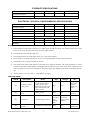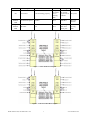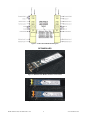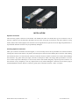
1
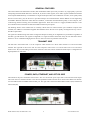
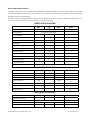
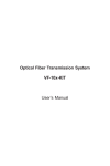
Model OTDV-1250
Broadcast Transport Links
OPERATING MANUAL
24926 Highway 108
Sierra Village, CA 95346
Phone: (800) 545-1022
Fax: (209 586-1022
Rev. X5
E-Mail: [email protected]
02/23/10
Table of Contents
Table of Contents............................................................................................................................................... 2
SAFETY............................................................................................................................................................... 3
Safety Precautions ................................................................................................................................................................3
Laser Safety Procedure .........................................................................................................................................................3
GENERAL FEATURES ....................................................................................................................................... 4
TRANSMIT SIDE................................................................................................................................................. 4
POWER, DATA, ETHERNET, AND OPTICS SIDE............................................................................................. 4
Alarm Output Specifications: ...............................................................................................................................................5
VIDEO SPECIFICATIONS................................................................................................................................... 5
AUDIO SPECIFICATIONS .................................................................................................................................. 5
DATA SPECIFICATIONS .................................................................................................................................... 5
ETHERNET SPECIFICATIONS .......................................................................................................................... 6
ELECTRICAL, PHYSICAL, ENVIRONMENTAL SPECIFICATIONS ................................................................. 6
NOTES: ................................................................................................................................................................................6
LED FUNCTIONS: ..............................................................................................................................................................6
Figure 1 - OTDV-1250-B Block Diagram ...................................................................................................................7
Figure 2 - OTDV-1250-TA/RA Block Diagram...........................................................................................................7
Figure 3 - OTDV-1250-TAA/RAA Block Diagram .....................................................................................................8
SFP MODULES................................................................................................................................................... 8
Figure 4 - MM 850nm SFP Module with Dual LC Connectors ...................................................................................8
Figure 5 - SM CWDM SFP Module with Dual LC Connectors...................................................................................8
Figure 6 - SM Bidirectional SFP Module with Single SC Connector ..........................................................................9
INSTALLATION ................................................................................................................................................... 9
Optical Connectors ...............................................................................................................................................................9
Cleaning Optical Connectors ................................................................................................................................................9
ORDERING INFORMATION ............................................................................................................................. 10
Model OTDV-1250, 025-000571 Rev. X5
2
www.olsontech.com
SAFETY
Safety Precautions
The optical emissions from the units are laser-based and may present eye hazards if improperly used. NEVER USE ANY
KIND OF OPTICAL INSTRUMENT TO VIEW THE OPTICAL OUTPUT OF THE UNIT. Be careful when
working with optical fibers. Fibers can cause painful injury if they penetrate the skin.
Laser Safety Procedure
ALWAYS read the product data sheet and the laser safety label before powering the product. Note the operation wavelength, optical output power and safety classifications.
If safety goggles or other eye protection are used, be certain that the protection is effective at the wavelength emitted by
the device under test BEFORE applying power.
ALWAYS connect a fiber to the output of the device BEFORE power is applied. Power should never be applied without
an attached fiber. If the device has a connector output, a connector should be attached that is connected to a fiber. This
will ensure that all light is confined within the fiber waveguide, virtually eliminating all potential hazard.
NEVER look at the end of the fiber to see if light is coming out. NEVER! Most fiber optic laser wavelengths (1310 nm
and 1550 nm) are totally invisible to the unaided eye and will cause permanent damage. Shorter wavelengths lasers (e.g.,
780 nm) are visible and are very damaging. Always use instruments, such as an optical power meter, to verify light output.
NEVER, NEVER, NEVER look into the end of a fiber on a powered device with ANY sort of magnifying device. This
includes microscopes, eye loupes and magnifying glasses. This WILL cause a permanent and irreversible burn on your
retina. Always double check that power is disconnected before using such devices. If possible, completely disconnect the
unit from any power source.
If you have questions about laser safety procedures, please call Olson Technology before powering your product.
Model OTDV-1250, 025-000571 Rev. X5
3
www.olsontech.com
GENERAL FEATURES
The Olson OTDV-1250 Video/Stereo Audio, Data and Ethernet Fiber Optic Link provides a very high-quality system for
transporting baseband NTSC RS-250 or PAL B, D, G, H and I video signals, stereo audio signals and bidirectional data
with complete EMI immunity via multimode or single-mode optical fiber. The combination of video, stereo quality audio,
data for touch screens, pan, tilt & zoom or pure data transport for communications and the addition of auto-negotiating
10/100Mb/s Ethernet make these links ideal for broadcast, contribution and distribution quality V/A/A transport, teleconferencing, distance learning, and surveillance applications. Each unit is built in a rugged, shielded enclosure. Units
are available with four channels of audio and unidirectional transport options.
The defining feature of the OTDV-1250 is versatility. While there are numerous fiber optic broadcast transport links
available, the addition of user/field-swappable SFP modules allows the unit to be rapidly reconfigured for any conceivable fiber requirement
All signals are handled using state-of-the-art digital techniques resulting in no degradation in performance regardless of
the fiber type and distance. All signals are digitized to a single serial data stream that easily fits into Gb/s data stream.
Extensive use of overhead messaging allows the two units to be aware of problems at the far end.
TRANSMIT SIDE
The left side is the transmit side. J1 is the composite video transmit. J2 is the S-video transmit. J3 is the stereo audio
transmit. The right side is the receive side. J4 is the composite video receive. J5 is the S-video receive. J6 is the stereo
audio receive. D1, D2, D3 & D4 give the status of the unit. Switch S1 selects whether the audio input is configured to be
high impedance or 600 Ohms.
POWER, DATA, ETHERNET, AND OPTICS SIDE
The left side is the power and alarm section. Pins 1 & 2 of J7 are the DC power input. Pins 3 and 4 are the alarm output.
The center section is the data interface. J8 is the low-speed data interface. Switch S2 is used to select RS-232 or RS-422.
J9 is the bidirectional 10/100Mb/s Ethernet data port. The right side contains the SFP module interface (J10) and the unit
status LED (D5).
Model OTDV-1250, 025-000571 Rev. X5
4
www.olsontech.com
Alarm Output Specifications:
The alarm output is driven by a normally closed MOSFET. It should be pulled to an external voltage (50V max) through
a resistor. The MOSFET has a typical “on” resistance of 330 ohms. The external resistor should be chosen such that the
maximum current is less than 25mA.
The alarm output is at high impedance when the unit is functioning properly, and at low impedance when there is no
power or no optical signal is present at the receiver, or the SFP is missing.
VIDEO SPECIFICATIONS
Min.
Typ.
Composite or S-Video
Input Signal
Output Signals
Composite and S-Video
I/O Impedance
75
Input Level
Max.
0.6
1.0
Output Level
Bandwidth
Units
(See Note 1)
Ohms
1.4
Vp-p
1.0
Vp-p(See Note 2)
6
MHz
SNR (NTC7 Lum-Weighted)
67
72.5
dB
SNR (Unified Lum-Weighted)
67
73.0
dB
Differential Gain
1.3
%
Differential Phase
0.7
°
0
0.25
0.50
%
Chrom-Lum Delay
-20
0
+20
ns
Chrom-Lum Gain
98
100
103
%
Line Time Distortion
10-bit 4:2:2 per ITU-R-BT.601
Conversion
AUDIO SPECIFICATIONS
Min.
Typ.
Max.
Units
Number of Channels
2
4
(See Note 3)
Frequency Response
20
20,000
Hz
THD+N
-85
-78
Input Impedance
600
Input Level (600 Ohm Bal.)
16
Gain
-1
17
0
dB
0.9
Vp-p
Max.
Units
10,000
16.5
Input Level (High Impedance,
Single Ended)
dB
Ohms (See Note
4)
dBu
DATA SPECIFICATIONS
Min.
Typ.
1
Number of Channels
Protocol
RS-232 or RS-422
(See Note 5)
Data Rate (RS-232)
155
kb/s
Data Rate (RS-422)
1
Mb/s
Model OTDV-1250, 025-000571 Rev. X5
5
www.olsontech.com
ETHERNET SPECIFICATIONS
Min.
Typ.
Max.
1
Number of Channels
Units
10Mb/s or 100Mb/s
Auto Negotiating
ELECTRICAL, PHYSICAL, ENVIRONMENTAL SPECIFICATIONS
DC Input Voltage
Min.
10
DC Current
0.30
Typ.
Storage Temp. Range
Humidity
0.53
A (See Note 6)
W (See Note 6)
25.4
oz.
11.5 x 6 (with base plate) x 1.25
inch
Module Weight
Operating Temp. Range
Units
VDC (See Note 6)
6
Power
Module Dimensions
Max.
20
0
+50
°C
-10
+60
°C
5
90
%
NOTES:
1) The transmitter accepts either composite or S-Video input. If both are present, the S-Video signal will be used.
The receiver always presents both composite and S-Video outputs.
2) The output level will track the input level.
3) The standard transceiver model offers either two or four audio channels.
4) Input impedance is switch selectable by the user. The high impedance setting is single end input.
5) The data protocol is switch selectable by the user.
6) The OTDV-1250 utilizes high-efficiency switching power supplies internally. The power dissipation is nearly
constant as the input voltage changes. The highest current draw will occur at the lowest input voltage and vice
versa. Note that excessive noise and ripple on the power supply may degrade some of the performance parameters.
7) All test results are at +25°C with a +15Volt DC power supply.
LED FUNCTIONS:
LED ID
Description
Green
Red
Orange
Off
D1
Composite video
input present
Solid green when composite video present and no
S-video present. Slow
flashing green when composite video present and
S-video present
N/A
N/A
No Composite
video present
D2
S-video input present
S-video present
N/A
N/A
No S-video
present
No optical
signal into far
end unit
No power
N/A
No video at
transmitter
D3
Unit status
Unit functioning properly
No optical signal
In or
missing
SFP
D4
Received video
present
Transmitter has valid video
N/A
Model OTDV-1250, 025-000571 Rev. X5
6
www.olsontech.com
LED ID
Description
Green
Red
Orange
Off
No optical
signal into far
end unit
No power
Unit status
Unit functioning properly
No optical signal
In or
missing
SFP
Left
Ethernet
LED
Connection Speed
10 Mb/s
N/A
100 Mb/s
No Connection
Right
Ethernet
LED
Rx Data
N/A
N/A
Receiving
data from
RJ-45 jack
Not receiving
data
D5
Figure 1 - OTDV-1250-B Block Diagram
Figure 2 - OTDV-1250-TA/RA Block Diagram
Model OTDV-1250, 025-000571 Rev. X5
7
www.olsontech.com
Figure 3 - OTDV-1250-TAA/RAA Block Diagram
SFP MODULES
Figure 4 - MM 850nm SFP Module with Dual LC Connectors
Figure 5 - SM CWDM SFP Module with Dual LC Connectors
Model OTDV-1250, 025-000571 Rev. X5
8
www.olsontech.com
Figure 6 - SM Bidirectional SFP Module with Single SC Connector
INSTALLATION
Optical Connectors
There are many optical connectors on the market. The OTDV-1250 offers LC and SC/UPC types of connectors. One of
the most common errors encountered in the field is the use of the wrong type of connectors. The most common is using
SC/PC (Flat) with SC/APC(angled). The connectors will fit together but the optical loss will be high and performance is
unpredictable and both connectors may be permanently damaged.
Cleaning Optical Connectors
Fiber optic connectors should be clean and capped, so one can usually remove the cap and make the connection without
cleaning the connector but if there is any doubt, clean the optical connectors before making the connection. After making
the connection, there is no need clean the connector while the connector remains connected. Use caution when handling
the connectors. Any grease from your finger, scratches or small pieces of dust can strongly affect performance. To clean,
use a lint-free wipe such as Kimwipes or cotton swab, moisten with alcohol and gently wipe the tip of the connector. Let
the connector air dry completely or use dry compressed air to dry. When making the connection, be sure the key aligns
with the bulkhead connector. With LC connectors, gently press in until the connector “clicks” in to place.
Model OTDV-1250, 025-000571 Rev. X5
9
www.olsontech.com
ORDERING INFORMATION
OTDV-1250 Platform
Description
OTDV-1250-B
NTSC Only - Bidirectional Digital Video, Dual Audio, Data Transport Link.
OTDV-1250-TA
NTSC Only - Transmit Only, Digital Video, Dual Audio, Data Transport Link.
OTDV-1250-RA
NTSC Only - Receive Only, Digital Video, Dual Audio, Data Transport Link.
OTDV-1250-TAA
NTSC Only - Transmit Only, Digital Video, Quad Audio, Data Transport Link.
OTDV-1250-RAA
NTSC Only - Receive Only, Digital Video, Quad Audio, Data Transport Link.
OTDV-1250P-B
PAL B, D, G, H and I Only - Bidirectional Digital Video, Dual Audio, Data Transport Link.
OTDV-1250P-TA
PAL B, D, G, H and I Only - Transmit Only, Digital Video, Dual Audio, Data Transport Link.
OTDV-1250P-RA
PAL B, D, G, H and I Only - Receive Only, Digital Video, Dual Audio, Data Transport Link.
OTDV-1250P-TAA
PAL B, D, G, H and I Only - Transmit Only, Digital Video, Quad Audio, Data Transport Link.
OTDV-1250P-RAA
PAL B, D, G, H and I Only - Receive Only, Digital Video, Quad Audio, Data Transport Link.
SFP Modules
Description
OTOLS-8512-02
SFP Optic Module, Dual MM Fiber , 850nm, 550 meter max, LC Connector
OTOLS-1312-30
SFP Optic Module, Dual SM Fiber 1310nm, 30km max, LC Connector
OTOLS-1512-80
SFP Optic Module, Dual SM Fiber 1550nm, 80km max, LC Connector
OTOLS-1612-CW-80-27
SFP Optic Module, Dual SM Fiber, CWDM, 1270nm, 80km max, LC Connector
OTOLS-1612-CW-80-29
SFP Optic Module, Dual SM Fiber, CWDM, 1290nm, 80km max, LC Connector
OTOLS-1612-CW-80-31
SFP Optic Module, Dual SM Fiber, CWDM, 1310nm, 80km max, LC Connector
OTOLS-1612-CW-80-33
SFP Optic Module, Dual SM Fiber, CWDM, 1330nm, 80km max, LC Connector
OTOLS-1612-CW-80-35
SFP Optic Module, Dual SM Fiber, CWDM, 1350nm, 80km max, LC Connector
OTOLS-1612-CW-80-37
SFP Optic Module, Dual SM Fiber, CWDM, 1370nm, 80km max, LC Connector
OTOLS-1612-CW-80-39
SFP Optic Module, Dual SM Fiber, CWDM, 1390nm, 80km max, LC Connector
OTOLS-1612-CW-80-41
SFP Optic Module, Dual SM Fiber, CWDM, 1410nm, 80km max, LC Connector
OTOLS-1612-CW-80-43
SFP Optic Module, Dual SM Fiber, CWDM, 1430nm, 80km max, LC Connector
OTOLS-1612-CW-80-45
SFP Optic Module, Dual SM Fiber, CWDM, 1450nm, 80km max, LC Connector
OTOLS-1612-CW-80-47
SFP Optic Module, Dual SM Fiber, CWDM, 1470nm, 80km max, LC Connector
OTOLS-1612-CW-80-49
SFP Optic Module, Dual SM Fiber, CWDM, 1490nm, 80km max, LC Connector
OTOLS-1612-CW-80-51
SFP Optic Module, Dual SM Fiber, CWDM, 1510nm, 80km max, LC Connector
OTOLS-1612-CW-80-53
SFP Optic Module, Dual SM Fiber, CWDM, 1530nm, 80km max, LC Connector
OTOLS-1612-CW-80-55
SFP Optic Module, Dual SM Fiber, CWDM, 1550nm, 80km max, LC Connector
OTOLS-1612-CW-80-57
SFP Optic Module for Dual SM Fiber, CWDM, 1570nm, 80km max, LC Connector
OTOLS-1612-CW-80-59
SFP Optic Module for Dual SM Fiber, CWDM, 1590nm, 80km max, LC Connector
OTOLS-1612-CW-80-61
SFP Optic Module for Dual SM Fiber, CWDM, 1610nm, 80km max, LC Connector
OTOLS-BI1312-10
SFP BiDi Optic Module for One SM Fiber, 1310nm Tx, 10km max, SC Connector
OTOLS-BI1512-10
SFP BiDi Optic Module for One SM Fiber, 1550nm Tx, 10km max, SC Connector
Power Supply Part Numbers
OTPS-12A-4P
Universal AC Power Supply, +12 Volts, 1.5 Amps
Model OTDV-1250, 025-000571 Rev. X5
10
www.olsontech.com